

Page 1

T
CCU4 Collector
Field Installation and Service
Guide
D R A F T !
Page 2

Identification
CCU4 Collector Field Installation and Service Guide
TDC-0359-000b 04/02
Trademark Notice
Itron is a registered trademark of Itron, Inc.
All other product names and logos in this manual are used for identification purposes only and may be trademarks or
registered trademarks of their respective companies.
Copyright Notice
Your company has the right to reproduce this contract document provided that such reproduction shall be subject to the
same use and disclosure restrictions contained in the Confidentiality and Non-Disclosure paragraphs in the Sales Contract.
© Copyright 2002 Itron, Inc. All rights reserved.
Compliance Statements
This equipment has been tested and found to comply with the limits for a Class B digital device, pursuant to Part 15 of the FCC Rules. These limits are designed to provide
reasonable protection against harmful interference in a residential installation. This equipment generates, uses, and can radiate radio frequency energy and , if not installed
and used in accordance with the instructions, may cause harmful interference to radio communications. However, there is no guarantee that interference will not occur
in a particular installation.
If this equipment does cause harmful interference to radio or television reception, which can be determined by turning the equipment off and on, the user is encouraged
to try to correct the interference by one or more of the following measures:
• Reorient or relocate the receiving antenna.
• Increase the separation between the equipment and receiver.
• Connect the equipment into an outlet on a circuit different from that to which the receiver is connected.
• Consult the dealer or an experienced radio or TV technician for help.
Warning
It is important that only authorized Itron personnel attempt repairs on Itron equipment as this might void any maintenance
contract with your company. Unauthorized service personnel might be subject to shock hazard on some Itron equipment
if removal of protective covers is attempted.
Suggestions
If you have comments or suggestions on how we may improve this document, send them to:
Itron, Inc.; Attention: Technical Communications; 2818 N. Sullivan Road; Spokane, WA 99216.
e-mail: techcomm@itron.com
ii CCU4 Collector Field Installation and Service Guide
TDC-0359-000b 04/02
DRAFT
Page 3

Contents
List of Figures. . . . . . . . . . . . . . . . . . . . . . . . . . . . . . . . . . . . . . . . . . . . . . . . . . . vii
List of Tables . . . . . . . . . . . . . . . . . . . . . . . . . . . . . . . . . . . . . . . . . . . . . . . . . . . ix
List of Procedures . . . . . . . . . . . . . . . . . . . . . . . . . . . . . . . . . . . . . . . . . . . . . . . xi
Before You Begin . . . . . . . . . . . . . . . . . . . . . . . . . . . . . . . . . . . . . . . . . . . . . . . xiii
How This Book is Organized . . . . . . . . . . . . . . . . . . . . . . . . . . . . . . . . . . . . . . . . . xiii
Conventions . . . . . . . . . . . . . . . . . . . . . . . . . . . . . . . . . . . . . . . . . . . . . . . . . . . . .xiii
Chapter 1 CCU4 Collector Overview . . . . . . . . . . . . . . . . . . . . . . . . . . . . . . . . . . . . . . . . . . .1
Features. . . . . . . . . . . . . . . . . . . . . . . . . . . . . . . . . . . . . . . . . . . . . . . . . . . . . . . . .1
Fixed Network Diagram . . . . . . . . . . . . . . . . . . . . . . . . . . . . . . . . . . . . . . . . . . . . . .2
CCU4 Collector Components . . . . . . . . . . . . . . . . . . . . . . . . . . . . . . . . . . . . . . . . . .3
Upper Housing . . . . . . . . . . . . . . . . . . . . . . . . . . . . . . . . . . . . . . . . . . . . . . . .4
CDPD Modem . . . . . . . . . . . . . . . . . . . . . . . . . . . . . . . . . . . . . . . . . . . . .4
POTS Modem . . . . . . . . . . . . . . . . . . . . . . . . . . . . . . . . . . . . . . . . . . . . .4
Communications Connector . . . . . . . . . . . . . . . . . . . . . . . . . . . . . . . . . . .4
Power Connector . . . . . . . . . . . . . . . . . . . . . . . . . . . . . . . . . . . . . . . . . . .4
Central Housing . . . . . . . . . . . . . . . . . . . . . . . . . . . . . . . . . . . . . . . . . . . . . . .4
Compact Flash Memory . . . . . . . . . . . . . . . . . . . . . . . . . . . . . . . . . . . . . .5
Receiver and Transmitter . . . . . . . . . . . . . . . . . . . . . . . . . . . . . . . . . . . . .5
Lower Housing . . . . . . . . . . . . . . . . . . . . . . . . . . . . . . . . . . . . . . . . . . . . . . . .5
Battery Pack . . . . . . . . . . . . . . . . . . . . . . . . . . . . . . . . . . . . . . . . . . . . . .5
Chapter 2 Installation Considerations . . . . . . . . . . . . . . . . . . . . . . . . . . . . . . . . . . . . . . . . . .7
ERT Compatibility . . . . . . . . . . . . . . . . . . . . . . . . . . . . . . . . . . . . . . . . . . . . . . . . . . 7
Collector to ERT Ratio and Distance . . . . . . . . . . . . . . . . . . . . . . . . . . . . . . . . . . . . .7
Radio Frequency. . . . . . . . . . . . . . . . . . . . . . . . . . . . . . . . . . . . . . . . . . . . . . . . . . .7
Installing a Davit on a Wood Pole . . . . . . . . . . . . . . . . . . . . . . . . . . . . . . . . . . . . . . .8
Required Tools and Hardware . . . . . . . . . . . . . . . . . . . . . . . . . . . . . . . . . . . . .8
Calculating Wind Load . . . . . . . . . . . . . . . . . . . . . . . . . . . . . . . . . . . . . . . . . . . . . .9
Example: Aluminum Light Pole Wind Load . . . . . . . . . . . . . . . . . . . . . . . . . . .10
RF Antenna Angle . . . . . . . . . . . . . . . . . . . . . . . . . . . . . . . . . . . . . . . . . . . . . . . . .10
DRAFT
Contents iii
Page 4

Measuring the Mounting Angle of a Pole or Davit. . . . . . . . . . . . . . . . . . . . . . .10
Grounding . . . . . . . . . . . . . . . . . . . . . . . . . . . . . . . . . . . . . . . . . . . . . . . . . . . . . .11
Unpacking the CCU4 Collector . . . . . . . . . . . . . . . . . . . . . . . . . . . . . . . . . . . . . . . .11
Packing Lists. . . . . . . . . . . . . . . . . . . . . . . . . . . . . . . . . . . . . . . . . . . . . . . . .11
CDPD Version (part #CCU-4011-001) . . . . . . . . . . . . . . . . . . . . . . . . . . .11
POTS Version (part # CCU-4012-001). . . . . . . . . . . . . . . . . . . . . . . . . . .11
Additional Required Parts. . . . . . . . . . . . . . . . . . . . . . . . . . . . . . . . . . . . . . . .12
Chapter 3 Installing the CCU4 Collector . . . . . . . . . . . . . . . . . . . . . . . . . . . . . . . . . . . . . . .13
Required Tools . . . . . . . . . . . . . . . . . . . . . . . . . . . . . . . . . . . . . . . . . . . . . . . . . . .13
Installation Procedure Summary. . . . . . . . . . . . . . . . . . . . . . . . . . . . . . . . . . . . . . .13
Installing the Hanging Plate . . . . . . . . . . . . . . . . . . . . . . . . . . . . . . . . . . . . . .14
Attaching the Collector to the Hanging Plate . . . . . . . . . . . . . . . . . . . . . . . . . .15
Attaching the RF Antenna. . . . . . . . . . . . . . . . . . . . . . . . . . . . . . . . . . . . . . . .16
Connecting the Means of Transmitting to the Headend . . . . . . . . . . . . . . . . . .17
Installing the Battery Pack . . . . . . . . . . . . . . . . . . . . . . . . . . . . . . . . . . . . . . .19
Supplying Power to the Collector . . . . . . . . . . . . . . . . . . . . . . . . . . . . . . . . . .20
Connecting the Collector to the Photoelectric Sensor . . . . . . . . . . . . . . . .20
Connecting the Collector to the Secondary Power Wires . . . . . . . . . . . . . .21
Verifying the Collector is Operational. . . . . . . . . . . . . . . . . . . . . . . . . . . . . . . .23
Chapter 4 Servicing the CCU4 Collector . . . . . . . . . . . . . . . . . . . . . . . . . . . . . . . . . . . . . . .25
Field Replaceable Parts . . . . . . . . . . . . . . . . . . . . . . . . . . . . . . . . . . . . . . . . . . . . .25
Replacing an Antenna . . . . . . . . . . . . . . . . . . . . . . . . . . . . . . . . . . . . . . . . . .25
Required Hardware and Tools . . . . . . . . . . . . . . . . . . . . . . . . . . . . . . . . .25
Replacing the Battery Pack. . . . . . . . . . . . . . . . . . . . . . . . . . . . . . . . . . . . . . .27
Required Hardware and Tools . . . . . . . . . . . . . . . . . . . . . . . . . . . . . . . . .27
Replacing the Collector . . . . . . . . . . . . . . . . . . . . . . . . . . . . . . . . . . . . . . . . .28
Required Tools. . . . . . . . . . . . . . . . . . . . . . . . . . . . . . . . . . . . . . . . . . . .28
Installation Procedure Summary . . . . . . . . . . . . . . . . . . . . . . . . . . . . . . .28
Appendix A CCU4 Collector Specifications . . . . . . . . . . . . . . . . . . . . . . . . . . . . . . . . . . . . . . . . .35
Dimensions and Weight. . . . . . . . . . . . . . . . . . . . . . . . . . . . . . . . . . . . . . . . . . . . .35
Environmental. . . . . . . . . . . . . . . . . . . . . . . . . . . . . . . . . . . . . . . . . . . . . . . . . . . .36
Power . . . . . . . . . . . . . . . . . . . . . . . . . . . . . . . . . . . . . . . . . . . . . . . . . . . . . . . . .36
AC Power . . . . . . . . . . . . . . . . . . . . . . . . . . . . . . . . . . . . . . . . . . . . . . . . . . .36
Battery . . . . . . . . . . . . . . . . . . . . . . . . . . . . . . . . . . . . . . . . . . . . . . . . . . . . .37
Communications Connector. . . . . . . . . . . . . . . . . . . . . . . . . . . . . . . . . . . . . . . . . .37
CDPD Modem. . . . . . . . . . . . . . . . . . . . . . . . . . . . . . . . . . . . . . . . . . . . . . . . . . . .38
POTS Modem . . . . . . . . . . . . . . . . . . . . . . . . . . . . . . . . . . . . . . . . . . . . . . . . . . . .38
POTS Cable . . . . . . . . . . . . . . . . . . . . . . . . . . . . . . . . . . . . . . . . . . . . . . . . . . . . .39
Receiver . . . . . . . . . . . . . . . . . . . . . . . . . . . . . . . . . . . . . . . . . . . . . . . . . . . . . . . .39
Transmitter. . . . . . . . . . . . . . . . . . . . . . . . . . . . . . . . . . . . . . . . . . . . . . . . . . . . . .40
iv CCU4 Collector Field Installation and Service Guide
TDC-0359-000b 04/02
DRAFT
Page 5

Agency Approvals . . . . . . . . . . . . . . . . . . . . . . . . . . . . . . . . . . . . . . . . . . . . . . . . .40
Appendix B Troubleshooting. . . . . . . . . . . . . . . . . . . . . . . . . . . . . . . . . . . . . . . . . . . . . . . . . . . . . 41
Index. . . . . . . . . . . . . . . . . . . . . . . . . . . . . . . . . . . . . . . . . . . . . . . . . . . . . . . . . . 43
DRAFT
Contents v
Page 6

Page 7

List of Figures
Attaching a Davit to the Wood Pole . . . . . . . . . . . . . . . . . . . . . . . . . . . . . . . . . . . . . . . . . 9
Attaching the CDPD Antenna . . . . . . . . . . . . . . . . . . . . . . . . . . . . . . . . . . . . . . . . . . . . 18
Attaching the Collector to the Hanging Plate. . . . . . . . . . . . . . . . . . . . . . . . . . . . . . . . . . 15
Attaching the RF Antenna . . . . . . . . . . . . . . . . . . . . . . . . . . . . . . . . . . . . . . . . . . . . . . . 17
CCU4 Collector Components. . . . . . . . . . . . . . . . . . . . . . . . . . . . . . . . . . . . . . . . . . . . . . 3
CCU4 Collector Dimensions . . . . . . . . . . . . . . . . . . . . . . . . . . . . . . . . . . . . . . . . . . . . . 35
Collector Shown Detached from Hanging Plate. . . . . . . . . . . . . . . . . . . . . . . . . . . . . . . . 31
Connecting the Collector to the Photoelectric Sensor . . . . . . . . . . . . . . . . . . . . . . . . . . . 21
Connecting the Collector to the Secondary Power Wires . . . . . . . . . . . . . . . . . . . . . . . . . 22
Connecting the POTS Cable . . . . . . . . . . . . . . . . . . . . . . . . . . . . . . . . . . . . . . . . . . . . . 19
Fixed Network with CCU4 Collector . . . . . . . . . . . . . . . . . . . . . . . . . . . . . . . . . . . . . . . . . 2
Installing the Battery Pack. . . . . . . . . . . . . . . . . . . . . . . . . . . . . . . . . . . . . . . . . . . . . . . 20
Installing the Hanging Plate on the Light Pole Davit. . . . . . . . . . . . . . . . . . . . . . . . . . . . . 14
Measuring the Mounting Angle of a Pole or Davit . . . . . . . . . . . . . . . . . . . . . . . . . . . . . . 10
RF and CDPD Antennas . . . . . . . . . . . . . . . . . . . . . . . . . . . . . . . . . . . . . . . . . . . . . . . . 26
DRAFT
List of Figures vii
Page 8

Page 9

List of Tables
AC Power Cable Wire Definitions. . . . . . . . . . . . . . . . . . . . . . . . . . . . . . . . . . . . . . . . . . 22
Battery Specifications . . . . . . . . . . . . . . . . . . . . . . . . . . . . . . . . . . . . . . . . . . . . . . . . . . 37
CDPD Modem Specifications. . . . . . . . . . . . . . . . . . . . . . . . . . . . . . . . . . . . . . . . . . . . . 38
CDPD Version Packing List . . . . . . . . . . . . . . . . . . . . . . . . . . . . . . . . . . . . . . . . . . . . . . 11
Communications Connector Specifications. . . . . . . . . . . . . . . . . . . . . . . . . . . . . . . . . . . 37
Environmental Specifications. . . . . . . . . . . . . . . . . . . . . . . . . . . . . . . . . . . . . . . . . . . . . 36
POTS Cable Wire Colors and Signal Names . . . . . . . . . . . . . . . . . . . . . . . . . . . . . . . . . . 18
POTS Cable Wire Specifications . . . . . . . . . . . . . . . . . . . . . . . . . . . . . . . . . . . . . . . . . . 39
POTS Modem Specifications . . . . . . . . . . . . . . . . . . . . . . . . . . . . . . . . . . . . . . . . . . . . . 38
POTS Version Packing List . . . . . . . . . . . . . . . . . . . . . . . . . . . . . . . . . . . . . . . . . . . . . . 11
Power Specifications . . . . . . . . . . . . . . . . . . . . . . . . . . . . . . . . . . . . . . . . . . . . . . . . . . 36
Receiver Specifications. . . . . . . . . . . . . . . . . . . . . . . . . . . . . . . . . . . . . . . . . . . . . . . . . 39
Required Power Cable by Installation. . . . . . . . . . . . . . . . . . . . . . . . . . . . . . . . . . . . . . . 12
Transmitter Specifications. . . . . . . . . . . . . . . . . . . . . . . . . . . . . . . . . . . . . . . . . . . . . . . 40
DRAFT
List of Tables ix
Page 10

Page 11

List of Procedures
Attach a Davit to a Wood Pole. . . . . . . . . . . . . . . . . . . . . . . . . . . . . . . . . . . . . . . . . . . . . 8
Attach the CDPD Antenna to the New Collector . . . . . . . . . . . . . . . . . . . . . . . . . . . . . . . 33
Attach the CDPD Antenna. . . . . . . . . . . . . . . . . . . . . . . . . . . . . . . . . . . . . . . . . . . . . . . 17
Attach the Collector to the Hanging Plate . . . . . . . . . . . . . . . . . . . . . . . . . . . . . . . . . . . . 15
Attach the New Collector to the Hanging Plate . . . . . . . . . . . . . . . . . . . . . . . . . . . . . . . . 31
Attach the RF Antenna to the New Collector. . . . . . . . . . . . . . . . . . . . . . . . . . . . . . . . . . 32
Attach the RF Antenna . . . . . . . . . . . . . . . . . . . . . . . . . . . . . . . . . . . . . . . . . . . . . . . . . 16
Connect the Collector to the Photoelectric Sensor . . . . . . . . . . . . . . . . . . . . . . . . . . . . . 20
Connect the Collector to the Secondary Power Wires . . . . . . . . . . . . . . . . . . . . . . . . . . . 22
Connect the POTS Cable . . . . . . . . . . . . . . . . . . . . . . . . . . . . . . . . . . . . . . . . . . . . . . . 18
Install the Battery Pack in the New Collector . . . . . . . . . . . . . . . . . . . . . . . . . . . . . . . . . 33
Install the Battery Pack . . . . . . . . . . . . . . . . . . . . . . . . . . . . . . . . . . . . . . . . . . . . . . . . . 19
Install the Hanging Plate . . . . . . . . . . . . . . . . . . . . . . . . . . . . . . . . . . . . . . . . . . . . . . . . 14
Reconnect the POTS Cable . . . . . . . . . . . . . . . . . . . . . . . . . . . . . . . . . . . . . . . . . . . . . . 33
Reconnect the Power Cable . . . . . . . . . . . . . . . . . . . . . . . . . . . . . . . . . . . . . . . . . . . . . 33
Remove the Current Collector . . . . . . . . . . . . . . . . . . . . . . . . . . . . . . . . . . . . . . . . . . . . 28
Replace an Antenna . . . . . . . . . . . . . . . . . . . . . . . . . . . . . . . . . . . . . . . . . . . . . . . . . . . 25
Replace the Battery Pack . . . . . . . . . . . . . . . . . . . . . . . . . . . . . . . . . . . . . . . . . . . . . . . 27
Verify the Collector is Operational . . . . . . . . . . . . . . . . . . . . . . . . . . . . . . . . . . . . . . . . . 23
Verify the New Collector is Operational . . . . . . . . . . . . . . . . . . . . . . . . . . . . . . . . . . . . . 34
DRAFT
List of Procedures xi
Page 12

Page 13

Before You Begin
This document describes the physical installation and maintenance of the CCU4 collector at the
site of installation and presumes any pre-installation configurations or modifications have
already been performed at the meter shop. For more information about procedures performed
prior to installation, see the CCU4 Collector Configuration Guide.
How This Book is Organized
• Chapter 1, “CCU4 Collector Overview” describes the features of the collector, its role in
the fixed network, and its individual components.
• Chapter 2, “Installation Considerations” addresses several topics to consider before
installing a CCU4 collector,including avoiding RF interference and calculating wind load.
This chapter also describes installing a davit on a wood pole.
• Chapter 3, “Installing the CCU4 Collector” describes installing the collector either on the
davit of a light pole or on a davit attached to a wood pole. This chapter also describes
supplying power to the collector using either the photoelectric sensor of a light pole or the
secondary power wires of a wood pole.
• Chapter 4, “Servicing the CCU4 Collector” describes replacing the antennas, the battery
pack, and the entire collector.
• Appendix A, “CCU4 Collector Specifications” provides environmental, electrical, and
physical specifications for the collector and its components.
Conventions
DRAFT
• Appendix B, “Troubleshooting” provides possible solutions to problems that may occur
while installing and servicing the CCU4 collector.
Hypertext links are blue.Example:See“Conventions” on page xiii for detailed information.
The last line in a table is defined by a thick gray line. If the table continues on another page, the
table number, title, and column headings are repeated on each page.
Before You Begin xiii
Page 14

Page 15

Chapter 1
CCU4 Collector Overview
Itron’s Cell Control Unit 4 (CCU4) collector is a self-contained device that collects energy
consumption and tamper data from Itron Encoder Receiver Transmitters (ERTs) installed on
commercial and residential utility meters, and then forwards this information over public
networks to a central data collection site (the fixed network headend). The collector’s modular
design and ability to read water, electric and gas meter data with the same unit provides a scalable
fixed network solution.
The CCU4 collector is installed outdoors on utility poles and is powered by a 120 VAC power
line. If AC power fails, the collector continues to operate on battery power for up to four hours.
The collector reads ERT Standard Consumption Messages (SCMs) and Interval Data Messages
(IDMs) at preset intervals on the 910-920 MHz unlicensed band (ISM) using a radio frequency
(RF) receiver. It then transmits the data at specified times of day to the headend through existing
telephone lines using a dial-up modem or through wireless transfer using a Cellular Digital
Packet Data (CDPD) modem and antenna. The collector also has a MAS band (952 MHz– 957
MHz) transmitter to excite ERT modules programmed as wake-up devices.
Once configured and installed, the CCU4 collector requires no onsite visits while functioning
normally. Changes to collection intervals or data transmission times, upgrades to software, and
other functions are all configured remotely from the headend. For more information on the
headend, see the Fixed Network 2.0 System Reference Guide.
Features
DRAFT
• Transfers data to the central data collection site over public networks, instead of the
proprietary Itron 1432 MHz network
• Internet Protocol (IP) interface provides access using standard internet-based software
applications
• Advanced digital radio technologies and full duplex radio increases the number of
readable endpoints
• Completely re-programmable from a remote location
• Scalable from a single device covering a few endpoints, to thousands of devices covering
large metropolitan areas
• Modular design allows adding different options to suit the installation and allows
increased functionality in the future
• Provides secure data transfer using standard encryption methods
• Includes 10 Base-T Ethernet interface for configuration, diagnostics, and high speed data
transfer
Chapter 1 - CCU4 Collector Overview 1
Page 16
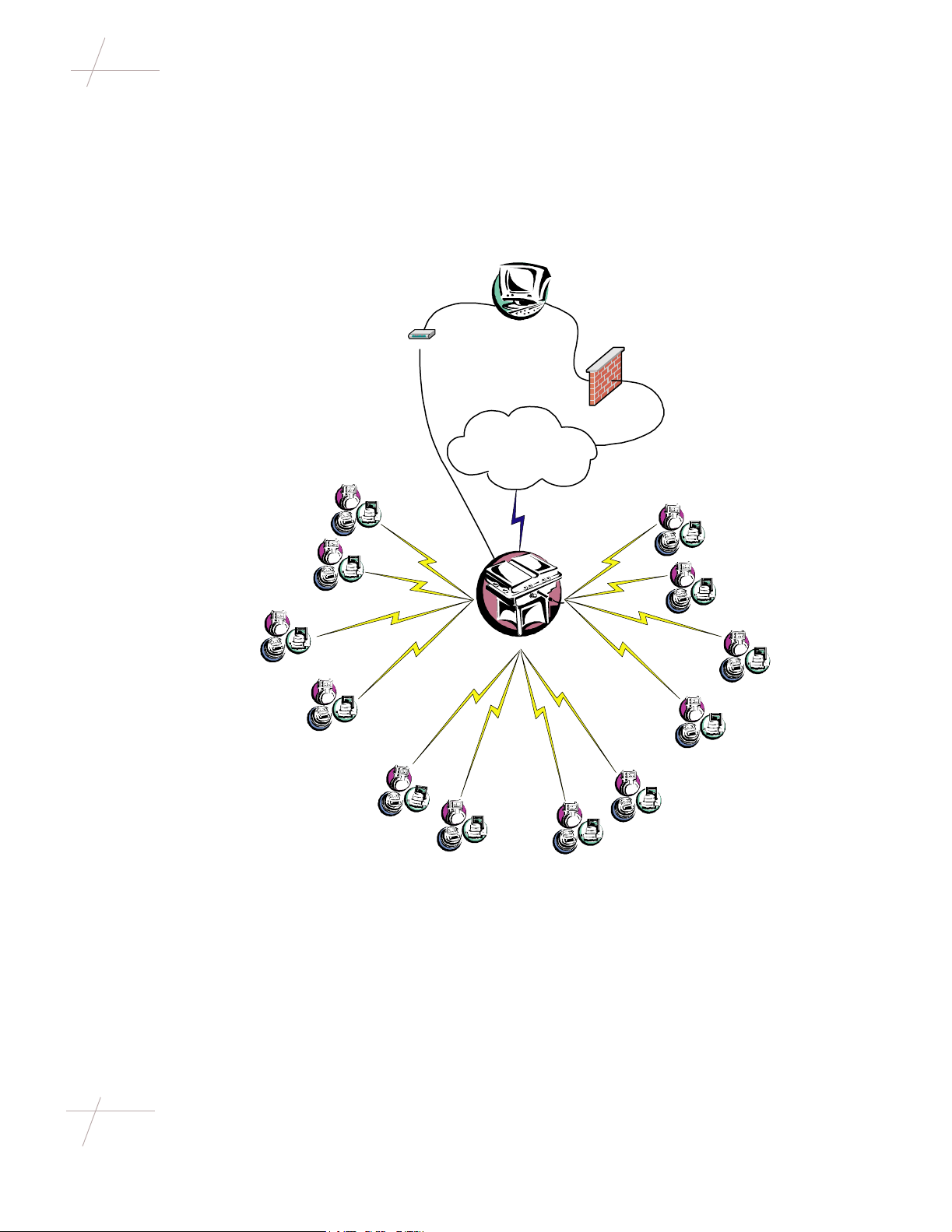
Fixed Network Diagram
Fixed Network Diagram
Figure 1 shows the role of the CCU4 collector in the overall fixed network. The collector reads
and stores meter data from water, gas, and electric ERT endpoints. It then transmits this data via
either POTS or the CDPD public network to the headend server.
Figure 1: Fixed Network with CCU4 Collector
Modem
POTS
Headend
Firewall
CDPD
Public Network
CDPD
ERT Endpoints
900 MHz 900 MHz
CCU4 Collector
900 MHz
ERT Endpoints
ERT Endpoints
2 CCU4 Collector Field Installation and Service Guide
TDC-0359-000b 04/02
DRAFT
Page 17
CCU4 Collector Components
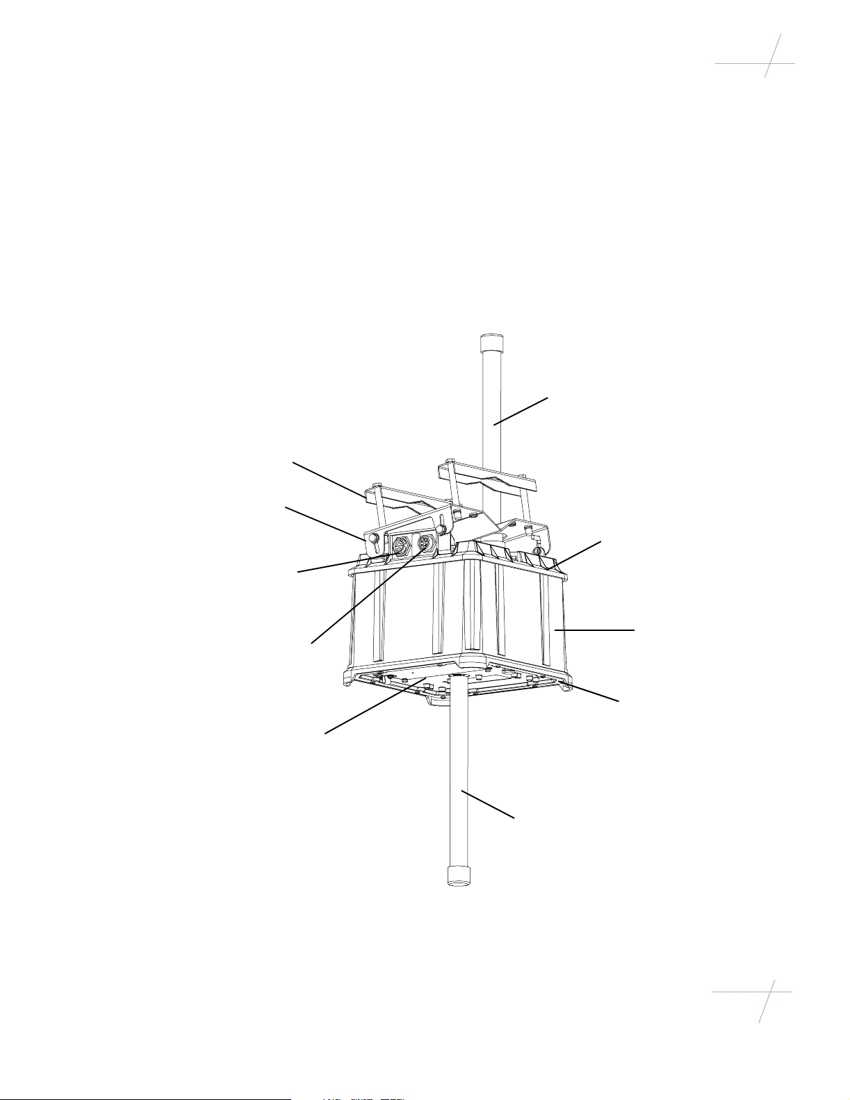
CCU4 Collector Components
The CCU4 collector’s modular design consists of a number of components fixed together to form
a single weatherproof device. The rugged, adjustable mounting bracket secures the device in high
winds and under heavy ice loads. Electrical components are designed into a plastic enclosure that
provides double insulation and a high level of safety while handling the device. All electrical
connections from the collector are fully isolated, meaning it does not require a connection to earth
ground.
If data is transferred over a wireless cellular public network, the collector requires only a power
connection. If data is transferred over a land-based public network, a telephone line or Ethernet
connection is also required.
Figure 2: CCU4 Collector Components
CDPD Antenna
Hanging Bracket
Hanging Plate
Communications
Connector
Power Connector
Battery Case
Upper Housing
Central Housing
Lower Housing
RF Antenna
DRAFT
Chapter 1 - CCU4 Collector Overview 3
Page 18

CCU4 Collector Components
Upper Housing
The upper housing contains the public network interface modem and the external power and
communications connectors. Each collector contains either a CDPD modem or a POTS (Plain
Old Telephone Service) dial-up modem, but not both at the same time. The upper housing can be
replaced to change the method of public network access.
CDPD Modem
The CDPD modem provides switched data communication services between the collector and the
service providers internet connection/frame relay. CDPD communication provides two-way,
fully digital, 19.2 KBPS packet data networking services. Due to protocol overhead and security,
the effective data rate for CDPD is between 9 KBPS and 14 KBPS, and will drop during periods
of interference and high network utilization. The antenna for the CDPD modem is integrated into
the top cover of the collector. CDPD service is offered by major cellular vendors in most
metropolitan areas of North America.
POTS Modem
The POTS modem is a dial-up modem operating at up to 56 KBPS. Electrical connection to the
modem is through the same modem interface board as used by the CDPD modem. The modem
is a transformer coupled device, which maintains the electrical isolation of the collector. Dial-up
internet service is offered by Internet Service Providers (ISPs) in most areas of North America.
Communications Connector
The communications connector is a transformer coupled connection (maintaining electrical
isolation) and is used on POTS versions of the collector to transmit data to the headend and
download software through POTS lines. The same connector is used in the meter shop to
establish an Ethernet connection, using different pins, during initial configuration and software
download.
Power Connector
The collector input AC connector is a five position circular 3A/300V connector. Pins 2, 3 and 4
are voided for high voltage line to line clearance. The five position circular connector is mounted
on the collector housing, providing a watertight connection point for external power sources.
Central Housing
The central housing is where the main processor, the compact flash memory, and the power
supply reside. The housing is well shielded to prevent interference with the sensitive radio
section.
Beneath the processor section, in the lower portion of the central housing, are the radio
transmitter and receiver.
4 CCU4 Collector Field Installation and Service Guide
TDC-0359-000b 04/02
DRAFT
Page 19

CCU4 Collector Components
Compact Flash Memory
The compact flash memory is a solid state hard drive that stores the complete operating system
and the collected data. It appears as a standard hard drive to the system. The compact flash
memory two copies of the operating system, so the entire network can be switched to a new
operating system at a scheduled time, but can still revert back to the earlier version if there is a
problem with the new operating system. If it becomes corrupted (virus/lightning strike/etc), the
entire compact flash drive can be formatted and reloaded over the public network.
Receiver and Transmitter
The receiver is a full duplex, enhanced version of the Itron G5 mobile radio receiver. A wideband
receiver identifies the presence and timing of an incoming ERT transmission, and a narrowband
digital Fast Fourier Transform (FFT) based decoder locates and decodes the ERT message.
The ERT wake-up transmitter is a modified version of the Itron G5 mobile transmitter. It operates
over the same MAS band (952 MHz – 957 MHz) but is optimized for a fixed network installation.
Lower Housing
The lower housing protects the radio from the outside environment and is where the battery pack
and the 900 MHz diplexer and are located. The diplexer controls transmitting to ERTs on the
MAS band and receiving from ERTs on the ISM band. The 900 MHz ERT antenna and ground
plane attach to the bottom of the lower housing, pointing down.
Battery Pack
The battery pack is sealed in its own compartment within the lower housing and is vented to the
outside air for safety. The battery pack is a four-cell sealed lead acid battery pack (8.8V, 2.5 Amp
hours / 22 WHr). It is field replaceable and designed to last 5 years. An automatically resetting
fuse protects the battery from shorts.
If the AC power fails, the battery pack maintains system functions for 4 hours. To conserve
power, the collector may reduce processor speed, turn off all unused peripherals, put the CDPD
modem into sleep mode (slowing web response time), and reduce the number of read cycles. This
lower performance mode also occurs during the 16-hour initial charge of the battery after
installation.
The collector generates alarms at the headend when the battery fails or when low capacity values
are detected.
DRAFT
Chapter 1 - CCU4 Collector Overview 5
Page 20

CCU4 Collector Components
6 CCU4 Collector Field Installation and Service Guide
TDC-0359-000b 04/02
DRAFT
Page 21

Chapter 2
Installation Considerations
ERT Compatibility
The CCU4 collector reads the following types of Itron ERTs and messages:
•25Series
•40Series
•41Series
•45Series
•50W
• SSD (Solid State Demand ERT)
• SCM and IDM messages- IDM first priority
Collector to ERT Ratio and Distance
Although the CCU4 collector potentially can read many more ERTs, to ensure all data is
collected, place one collector for every 100 unique ERTs.
The collector reads ERTs within a maximum radius of 800 ft, although some environmental,
weather, and terrain conditions can affect this distance.
Radio Frequency
To ensure RF signals are received, install the collector at elevations and locations where the
greatest number of endpoints are in direct line of sight of the collector.
Avoid installing collectors in following ways:
• Adjacent to or between tall buildings, signs, towers, or bridges
• Within 500 ft of high power RF transmitters (such as paging transmitters, cellular
• Near potential broadband sources of radiated RF energy (such as power line transformers
• Near swaying limbs, branches, or cables that could strike the collector
• Between or beneath highway overpasses, elevated train platforms, or tunnels
• Near tunnel entrances
• Near objects or devices (such as solar panels and signs) attached to the same pole
DRAFT
transmitters, and municipal communications transmitters)
and neon or fluorescent signs)
Chapter 2 - Installation Considerations 7
Page 22

Installing a Davit on a Wood Pole
Installing a Davit on a Wood Pole
The CCU4 collector is installed on the davit of a pole, which is the part of the pole that extends
out, away from the pole and is parallel to the ground. A light pole has an existing davit that holds
the light fixture, and the collector is installed about 6 in. behind the light fixture on the davit.
Wood poles do not usually have davits, but you can install one on the pole with a davit kit. If the
wood pole already has a davit attached, you do not need to add another unless installing the
collector on the davit exceeds the wind load rating of the davit, creates RF interference with other
equipment on or near the pole, or places the collector too near tree branches or other
environmental factors.
If you are installing the CCU4 collector on a wood pole without an existing davit you can install
a davit using the Itron CCU Upsweep Davit Kit or the Itron CCU Downsweep Davit Kit. The
upsweep and downsweep davit kits each contain a bracket with a davit and arm welded to it.
The davit arm protrudes away from the bracket either up (upsweep kit) or down (downsweep kit).
Choose between the upsweep or downsweep kit to provide the collector with clearance from
other equipment attached to the pole and from nearby tree branches or other environmental
factors.
The davit kit attaches to the wood pole with a long bolt that goes through the pole and a lag bolt
that goes into the pole. The bolts and washers required to install the davit are not included in the
kit, since the length of the longer bolt varies depending on the thickness of the pole.
Required Tools and Hardware
You need the following tools and hardware to install the upsweep or downsweep davit kit on a
wood pole:
• 1/2-inch diameter bolt long enough to insert completely through the wood pole
• 1/2-inch diameter lag bolt
• 1/2-inch diameter washer, lock washer, and nut
• Drill with 1/2-inch diameter drill bit
• Nut driver, wrench, or ratchet-wrench
To Attach a Davit to a Wood Pole
1. Place the support arm against the pole and mark the position of the top slotted hole.
2. Drill a hole through the pole at the marked position.
3. Insert a bolt through the pole so that it protrudes 1/2 inch out the other side.
4. Insert the washer, lock washer, and nut onto the protruding tip of the through-bolt, and
tighten the nut until the bracket is held in place.
5. Slip the slotted hole of the bracket over the head of the through-bolt, and slide the bracket
down so that the head of the through-bolt is captured in the slot.
6. Insert the lag bolt through the bottom hole of the bracket and into the pole.
8 CCU4 Collector Field Installation and Service Guide
TDC-0359-000b 04/02
DRAFT
Page 23

Calculating Wind Load
7. Tighten the through-bolt and the lag bolt until the bracket is firmly attached to the pole and
the end of the support arm is parallel to the ground.
Figure 3: Attaching a Davit to the Wood Pole
Davit
Wood Pole
Upsweep Arm
Through-Bolt
Lag Bolt
Downsweep Arm
Calculating Wind Load
Wind load is the combination of maximum weight and Effective Projected Area (EPA) that the
davit or pole can withstand. EPA, the actual projected area of an object multiplied by its
coefficient of drag, is expressed as a decimal, such as 1.3. The manufacturer of the davit or pole
should provide wind load rating specifications.
Before mounting a CCU4 collector onto the davit of a pole, you must calculate the wind load and
determine whether the combined weight and the combined EPA of the collector and any light
fixture or other equipment already installed on the davit exceeds the limits for which the
particular davit and pole are rated.
Follow the equations below to calculate wind load for each installation:
(weight of light fixture, etc.) + (weight of CCU4 and mounting hardware) = total weight
(EPA of light fixture, etc.) + (EPA of CCU4 and mounting hardware) = total EPA
The following example describes calculating the wind load for a light pole with one light fixture
and one CCU4 collector.
DRAFT
Chapter 2 - Installation Considerations 9
Page 24

RF Antenna Angle
Example: Aluminum Light Pole Wind Load
A G.E. Light Systems davit and pole support a maximum weight of 60 pounds and a maximum
EPA of 1.5, rated at 100 MPHI (Miles Per Hour Isotach). The existing light fixture weighs 35
pounds and has a .7 EPA. The CCU4 collector (including mounting hardware) weighs 23 pounds
and has a .7 EPA. The combined weight of the collector and the light fixture is 58 pounds. The
combined EPA of the collector and the light fixture is 1.4.
The following equation shows the calculations for this installation:
(35 lb) + (23 lb) = 58 lb
(.7) + (.7) = 1.4
Since the combined totals are less than the maximum weight (60 pounds) and the maximum EPA
(1.5) ratings of the davit, the installation is feasible.
RF Antenna Angle
Regardless of the specific attachment point, the collector antenna must be vertical (plumb),
extending downward, perpendicular to the horizon.
Measuring the Mounting Angle of a Pole or Davit
Two factors involved in achieving a plumb installation are the angles of the pole and the davit.
Using an Itron Protractor, you can measure the angles of the pole and davit, as described below.
To measure the mounting angle of a davit, place the Itron Protractor on top of the davit above
where the collector will be mounted. Verify the angle is no more than 15 degrees away from 0
degrees.
To measure the slant of a wood pole, place the Itron Protractor against the wood pole. Verify the
angle is no more than 15 degrees away from 90 degrees.
Figure 4: Measuring the Mounting Angle of a Pole or Davit
Itron Protractor
Wood
Wood Pole
Pole
15015
Davit
Davit
759075
If either angle is more than 15 degrees, adjust the angle of the collector when attaching it to the
hanging plate by varying the connection points of the bolts connecting the hanging plate to the
collector’s L-brackets.
10 CCU4 Collector Field Installation and Service Guide
TDC-0359-000b 04/02
DRAFT
Page 25

Grounding
The CCU4 collector does not require an earth ground connection because the unit is sealed and
encased in plastic.
Unpacking the CCU4 Collector
Remove the CCU4 collector from its shipping container and verify the protective foam pieces are
not severely damaged. If these pieces are damaged, and the collector has significant visible
damage, it may not function correctly.
Important The collector must remain protected at all times prior to installation. After
unpacking the collector to configure it prior to installation, save the packing container and
packing materials to use again when transporting the unit to its location in the field. After
installing the collector, save the container and materials for transport in the event the
collector malfunctions and must be shipped to Itron for repair.
Packing Lists
The following parts are included in each container:
Grounding
CDPD Version (part #CCU-4011-001)
Table 1: CDPD Version Packing List
Quantity Part Description Part Number
1 Battery pack BAT-0019-001
1 CDPD antenna MSE-0105-001
1 RF antenna MSE-0104-001
1 CCU4 collector CCU-4011-001
POTS Version (part # CCU-4012-001)
Table 2: POTS Version Packing List
Quantity Part Description Part Number
1 Battery pack BAT-0019-001
1 POTS cable CBA-0167-001
1 RF antenna MSE-0104-001
1 CCU4 collector CCU-4012-001
DRAFT
Chapter 2 - Installation Considerations 11
Page 26

Unpacking the CCU4 Collector
Additional Required Parts
In addition to the contents of the CCU4 container, you must have the Pole Mount Kit (part #
CCU-4401-001, shipped separately), and one of the power cables (shipped separately) listed in
the table below, depending on the type of installation.
Table 3: Required Power Cable by Installation
Type of Installation Required Power Cable Length Part Number
Light Pole Light Pole Power Cable 4 ft CBA-0111-011
Wood Pole Three-Conductor Power Cable 12 ft CBL-0007-001
If anything is missing, contact your customer service representative immediately for a
replacement part.
8 ft CBA-0111-012
12 ft CBA-0111-013
12 CCU4 Collector Field Installation and Service Guide
TDC-0359-000b 04/02
DRAFT
Page 27

Chapter 3
Installing the CCU4 Collector
This installation involves attaching the CCU4 collector to either the davit (the arm holding the
light fixture) of the light pole or to a davit that has been installed on a wood pole. In either case,
a davit must already be available on which to install the collector. Once the collector is installed,
you must supply it with power either from the photoelectric sensor of the street lamp or from the
secondary power wires of the wood pole.
Required Tools
You need the following tools to install the CCU4 collector on a davit:
• 7/16-inch nut driver, wrench, or ratchet-wrench
• Inch-pound torque wrench with 7/16-inch socket
• Flathead screwdriver
• Itron bubble-level to check the plumb of the collector
• AC circuit tester or volt meter (if installing on a light pole)
• Wire stripper and wire cable sleeve (if installing on a wood pole)
Installation Procedure Summary
You must perform the following procedures to install the CCU4 collector on a davit:
1. Install the hanging plate.
2. Attach the collector to the hanging plate.
3. Attach the RF antenna.
4. Connect the means of transmitting to the headend.
5. Install the battery pack.
6. Supply power to the collector.
7. Verify the collector is operational.
DRAFT
Chapter 3 - Installing the CCU4 Collector 13
Page 28

Installation Procedure Summary
Installing the Hanging Plate
The hanging plate attaches to the light pole davit with two brackets that have sharp teeth on the
side that contacts the davit, keeping the hanging plate firmly in place. When replacing the
collector with a new one, you can remove the old collector without removing the hanging plate,
thus speeding the replacement and maintaining the general placement of the collector.
To Install the Hanging Plate
1. Using two of the 1/4-20 x 3-inch hex-head bolts, loosely bolt one end of each bracket onto
the hanging plate so that the brackets swing.
2. With one hand, hold the hanging plate against the bottom of the davit at the place you are
installing the
over the davit.
Note Install the hanging plate at least six inches from the light fixture to ensure the light
cover can open when the bulb is changed.
3. While still holding the hanging plate in place, insert the two remaining bolts through the
unsecured ends of the brackets and into the hanging plate.
4. Tighten all four bolts with your fingers until the plate stays in place.
5. Moving in a cross (X) pattern, torque all four bolts to between 50- and 60-inch pounds.
Caution To achieve the clamping force needed to withstand 100 MPH winds, torque the
four hex-head bolts to the specification listed. If the bolts are under-torqued, the necessary
clamping force may not be achieved, and if they are over torqued, the brackets can become
over-stressed, which may also reduce clamping force.
collector
, and with the other hand, swing the unsecured ends of the brackets
Figure 5: Installing the Hanging Plate on the Light Pole Davit
14 CCU4 Collector Field Installation and Service Guide
TDC-0359-000b 04/02
DRAFT
Page 29

Installation Procedure Summary
Attaching the Collector to the Hanging Plate
The collector attaches to the hanging plate with four bolts inserted through the slots in the plate
and into holes in four L-brackets on the collector. You can adjust the collector so the RF antenna
is plumb by sliding the bolts up and down in the slots and tightening the bolts when the antenna
is perpendicular to the horizon.
To Attach the Collector to the Hanging Plate
1. With one hand, hold the
the unit with the slots on the hanging plate.
2. Insert each of the four 1/4-20 x 3/4-inch hex-head bolts through a slot and into an L-bracket
hole.
3. Tighten the bolts just enough that the unit hangs from the plate but is still loose enough
that you can slide it up and down in the slots.
Figure 6: Attaching the Collector to the Hanging Plate
collector
below the hanging plate and align the L-bracket holes on
DRAFT
L-bracket
Chapter 3 - Installing the CCU4 Collector 15
Page 30

Installation Procedure Summary
4. To adjust the unit for plumb, place the bubble-level tool on a flat surface of the
collector
and, with one hand, tilt the unit until the bubble in the leveling tool is away from the wall.
It is not necessary to center the bubble in the circle.
Bubble away
from wall
Note If you do not have a bubble-level, adjust the unit so that the bottom is parallel with
the ground. This ensures the antenna is plumb (perpendicular to the ground, pointing
down) when you attach it in the next procedure.
5. With the other hand, move in a cross (X) pattern and torque all four bolts to between 50and 60-inch pounds.
Caution To achieve the clamping force needed to withstand 100 MPH winds, torque the
four hex-head bolts to the specification listed. If the bolts are under-torqued, the necessary
clamping force may not be achieved, and if they are over torqued, the brackets can become
over-stressed, which could also reduce clamping force.
Attaching the RF Antenna
Both the POTS version and the CDPD version of the collector have an RF antenna that attaches
to the collector bottom. The CDPD version has a second antenna that attaches to the collector top.
You will install the CDPD antenna in the next procedure if you are installing that version of the
collector.
Caution The two antennas differ in appearance and function. You can distinguish the
CDPD antenna from the RF antenna by the two additional knobs on the base of the CDPD
antenna. Installing an antenna in the wrong place may damage the collector and will cause
it to fail to work as intended.
To Attach the RF Antenna
1. Align the RF antenna with the N-connector on the bottom of the unit.
16 CCU4 Collector Field Installation and Service Guide
TDC-0359-000b 04/02
DRAFT
Page 31

Installation Procedure Summary
2. Press the antenna onto the connector and turn the antenna clockwise until it no longer turns
andisfirmlyinplace.
Figure 7: Attaching the RF Antenna
RF Antenna
Connecting the Means of Transmitting to the Headend
If you are installing the CDPD version, you must attach the CDPD antenna. If you are installing
the POTS version, you must connect one end of the POTS cable to the communications connector
on the collector and connect the other end to the POTS line nearest the pole.
To Attach the CDPD Antenna
1. Insert the antenna through the hole in the top of the hanging plate and align it with the Nconnector on top of the unit.
DRAFT
Chapter 3 - Installing the CCU4 Collector 17
Page 32

Installation Procedure Summary
2. Press the antenna onto the connector, and turn the antenna clockwise until it no longer
turns and is firmly in place.
Figure 8: Attaching the CDPD Antenna
CDPD Antenna
RF Antenna
To Connect the POTS Cable
1. Determine the distance from the
collector
to the POTS port.
2. Cut the cable to the appropriate length, leaving enough cable for routing and slack.
3. Hard-wire the unterminated end of the cable to the POTS port. Refer to the table below to
identify each wire.
Table 4: POTS Cable Wire Colors and Signal Names
Wire Color Signal Name
Green Tip
Red Ring
Black Ground
Yellow no connection
18 CCU4 Collector Field Installation and Service Guide
TDC-0359-000b 04/02
DRAFT
Page 33

Installation Procedure Summary
4. Run the other end of the cable to the communication port on the CCU4 collector. Wrap
any excess cable around the davit or use tie wraps (not included) to secure the cable.
5. Connect the cable to the communications port on the collector.
Figure 9: Connecting the POTS Cable
To P OT S
Communications
Port
Installing the Battery Pack
The battery pack ships uninstalled in the same container as the collector. If the collector was
configured at the depot, the battery pack may be stored in the battery compartment for transport.
Caution Do not connect the battery pack to the collector until the collector is in place on
the pole. If you connect the battery pack prior to installation, the collector may record
erroneous data and the battery pack may completely lose power.
To Install the Battery Pack
1. Using a flathead screwdriver, loosen the four captive-screws holding the battery case in
place.
2. Pull out the battery case.
The strap keeps the case connected to the bottom of the
collector
.
DRAFT
3. Connect the battery pack to the connector inside the battery compartment.
4. Place the battery pack inside the battery case and insert the case into the battery
compartment.
Chapter 3 - Installing the CCU4 Collector 19
Page 34

Installation Procedure Summary
5. While pressing the battery case into the battery compartment, finger-tighten the four
captive-screws until the battery case is held in place.
6. Using the flathead screwdriver, tighten the four captive-screws until the battery case is
firmly in place.
Figure 10: Installing the Battery Pack
Battery
Case
Battery
Pack
Supplying Power to the Collector
Once the collector is installed on the davit, you must supply it with power either from the
photoelectric sensor of the street lamp or from the secondary power wires of the wood pole.
Connecting the Collector to the Photoelectric Sensor
To power the collector when installing it on a light pole, you must remove the photoelectric
sensor, insert the power adapter end of the power cable into the socket, and replace the
photoelectric sensor.
To Connect the Collector to the Photoelectric Sensor
1. Verify power is available by using a voltmeter or AC circuit tester on the street lamp.
Note Before removing the photoelectric sensor, note the current orientation of the sensor
window. You must restore the sensor window to the same orientation (usually north) when
finished.
If you do not have a voltmeter or AC circuit tester, verify power by placing your hand over
the photoelectric sensor window.
If power is available, the lamp lights after a brief delay.
20 CCU4 Collector Field Installation and Service Guide
TDC-0359-000b 04/02
DRAFT
Page 35

Installation Procedure Summary
2. If you did not already do so to verify power, remove the photoelectric sensor, and insert
the power cable plug adapter into the socket.
3. Replace the photoelectric sensor, taking care to restore the sensor window to its original
orientation.
4. Wrap any excess cable around the davit or use tie-wraps (not included) to secure the cable
away from the unit.
5. Connect the other end of the power cable to the 5-pin power connector on the
collector
6. Verify the streetlight still works by covering the photoelectric sensor window with your
hand.
Figure 11: Connecting the Collector to the Photoelectric Sensor
Photoelectric
Sensor
Power Adapter
.
DRAFT
Power
Connector
Connecting the Collector to the Secondary Power Wires
To power the collector when installing it on a wood pole, you must strip the power cable with
wire strippers and connect the individual wires to the 120V and neutral wires on the pole. You do
not need to connect the power cable to earth ground because the collector housing is sealed and
plastic, and all electrical connections from the collector are fully isolated.
Chapter 3 - Installing the CCU4 Collector 21
Page 36

Installation Procedure Summary
To Connect the Collector to the Secondary Power Wires
1. At the power line, connect the unterminated end of the cable to the power source on the
pole, as shown below. Consult the following table for definitions of the wires in the AC
power cable.
Table 5: AC Power Cable Wire Definitions
Wire Description Pin #
Black Line side 5
White Neutral 1
Figure 12: Connecting the Collector to the Secondary Power Wires
120V
Drip Loops
Shielding for
Power Cable
Power Cable
from CCU4
Cable
Ties
Neutral
2. Wrap any excess cable around the davit or use tie-wraps (not included) to secure the cable
away from the unit.
3. Connect the other end of the power cable to the 5-pin power connector on the
22 CCU4 Collector Field Installation and Service Guide
TDC-0359-000b 04/02
collector
DRAFT
.
Page 37

Installation Procedure Summary
Verifying the Collector is Operational
Once the collector is installed and receiving power, it should appear onscreen at the headend. To
verify the collector is receiving power and the software is operating correctly, you must call the
headend and give the administrator the IP address and the number of the collector. If the
administrator identifies the collector onscreen, the installation is complete.
To Verify the Collector is Operational
1. Call the headend.
2. Give the administrator the ID number of the collector and its IP address.
3. Wait for the administrator to identify the collector onscreen.
• If the administrator sees the collector, the installation is complete.
• If the administrator does not see the collector, proceed to the troubleshooting section
of this manual.
DRAFT
Chapter 3 - Installing the CCU4 Collector 23
Page 38

Page 39

Chapter 4
Servicing the CCU4 Collector
Field Replaceable Parts
The following maintenance procedures are the only ones you can perform in the field:
• Replace an antenna
• Replace the battery pack
• Replace the collector
Each procedure is described on the following pages.
Replacing an Antenna
The POTS modem version has only one antenna, the RF antenna that attaches to the collector
bottom. The CDPD modem version has two antennas: the RF antenna on the bottom of the
collector and the CDPD antenna on the top.
Caution The two antennas differ in appearance and function. You can distinguish the
CDPD antenna from the RF antenna by the two additional knobs on the base of the CDPD
antenna. Be sure the new antenna is the same type as the one you are replacing. Installing
an antenna in the wrong place may damage the collector and will cause it to fail to work
as intended. Consult the following illustration to identify each antenna.
DRAFT
Required Hardware and Tools
You do not need special tools to replace an antenna.
To Replace an Antenna
1. Turn the antenna counter-clockwise and unscrew it from the N-connector on the
2. Align the new antenna with the N-connector.
Chapter 4 - Servicing the CCU4 Collector 25
collector
.
Page 40

Field Replaceable Parts
3. Press the antenna onto the connector while turning the antenna clockwise until it no longer
turns and is firmly in place.
Figure 13: RF and CDPD Antennas
CDPD Antenna
RF Antenna
26 CCU4 Collector Field Installation and Service Guide
TDC-0359-000b 04/02
DRAFT
Page 41

Field Replaceable Parts
Replacing the Battery Pack
The power supply connected to the CCU4 collector charges the battery pack. The battery pack
can power the collector for 4 hours after power is lost and should be replaced every 5 years. Once
the new battery pack is installed, it must charge for 16 hours before it is fully powered.
Required Hardware and Tools
You need a flathead screwdriver to replace the battery pack.
To Replace the Battery Pack
1. Using a flathead screwdriver, loosen the four captive-screws holding the battery case in
place.
2. Pull out the battery case.
The strap keeps the case connected to the bottom of the
3. Disconnect the battery pack from the connector inside the battery compartment, and set the
old battery pack aside.
4. Connect the new battery pack to the connector inside the battery compartment.
5. Place the battery pack inside the battery case and insert the case into the battery
compartment.
Battery Case
collector
.
Battery Pack
DRAFT
6. While pressing the battery case into the battery compartment, finger-tighten the four
captive-screws until the battery case is held in place.
7. Using the flathead screwdriver, tighten the four captive-screws until the battery case is
firmly in place.
8. Recycle the old battery pack per office standards and local regulations.
Chapter 4 - Servicing the CCU4 Collector 27
Page 42

Field Replaceable Parts
Replacing the Collector
Required Tools
You need the following tools to replace the CCU4 collector:
• 7/16-inch nut driver, wrench, or ratchet-wrench
• Inch-pound torque wrench with 7/16-inch socket
• Flathead screwdriver
• Itron Bubble-level
Installation Procedure Summary
You must perform the following procedures to replace a CCU4 collector:
1. Remove the current collector.
2. Attach the new collector to the hanging plate.
3. Attach the RF antenna.
4. Reconnect the means of transmitting to the headend.
5. Install the battery pack.
6. Reconnect the power cable.
7. Verify the new collector is operational.
Removing the Current Collector
Because the collector attaches to the hanging plate, rather than directly to the davit, removing a
collector is much simpler than installing one. To physically remove the collector, you need only
remove the four bolts inserted through the L-brackets of the collector.
However, before actually removing the collector from the hanging plate, you must disconnect the
battery and the power cable, remove the RF antenna, and remove the means of communicating
with the headend. This last process involves either disconnecting the POTS cable or removing
the CDPD antenna, depending on the version of the collector you are removing.
To Remove the Current Collector
1. Using a flathead screwdriver, loosen the four captive-screws holding the battery case in
place.
2. Pull out the battery case.
The strap keeps the case connected to the bottom of the
3. Disconnect the battery pack from the connector inside the battery compartment.
4. Place the battery pack back inside the battery case and insert the case into the battery
compartment.
collector
.
5. While pressing the battery case into the battery compartment, finger-tighten the four
captive-screws until the battery case is held in place.
28 CCU4 Collector Field Installation and Service Guide
TDC-0359-000b 04/02
DRAFT
Page 43

Field Replaceable Parts
6. Using the flathead screwdriver, tighten the four captive-screws until the battery case is
firmly in place.
Battery Case
Battery Pack
7. Disconnect the power cable from the 5-pin power connector on the
collector
.
8. Turn the RF antenna on the bottom of the collector counter-clockwise, and unscrew it from
the N-connector.
9. Remove the means of communicating with the headend. This depends on which version
of the collector you are removing.
• If you are removing the POTS version (part # CCU-4012-001), disconnect the POTS
cable from the communications port on the collector.
DRAFT
Chapter 4 - Servicing the CCU4 Collector 29
Page 44

Field Replaceable Parts
• If you are removing the CDPD version (part # CCU-4011-001), turn the CDPD
antenna on top of the collector counter-clockwise, and unscrew it from the N-connector.
CDPD Antenna (part #
CCU-4011-001 only)
POTS Cable (part #
CCU-4012-001 only)
Power Cable
10. With one hand, hold the bottom of the
11. With the other hand, use a
7/16-inch nut driver, wrench, or ratchet-wrench to
bolts holding the collector to the hanging plate.
collector
RF Antenna
.
remove the four
30 CCU4 Collector Field Installation and Service Guide
TDC-0359-000b 04/02
DRAFT
Page 45

Field Replaceable Parts
12. Lower the collector down and away from the hanging plate, and set it aside.
Figure 14: Collector Shown Detached from Hanging Plate
Attaching the New Collector to the Hanging Plate
To Attach the New Collector to the Hanging Plate
1. With one hand, hold the
the unit with the slots on the hanging plate.
2. Insert each of the four 1/4-20 x 3/4-inch hex-head bolts through a slot and into an L-bracket
hole.
3. Tighten the bolts just enough that the unit hangs from the plate but is still loose enough
that you can slide it up and down in the slots.
collector
below the hanging plate and align the L-bracket holes on
DRAFT
Chapter 4 - Servicing the CCU4 Collector 31
Page 46

Field Replaceable Parts
4. To adjust the unit for plumb, place the bubble-level tool on a flat surface of the
collector
and, with one hand, tilt the unit until the bubble in the leveling tool is away from the wall.
It is not necessary to center the bubble in the circle.
Bubble away
from wall
Note If you do not have a bubble-level, adjust the unit so that the bottom is parallel with
the ground. This ensures the antenna is plumb (perpendicular to the ground, pointing
down) when you attach it in the next procedure.
5. With the other hand, move in a cross (X) pattern and torque all four bolts to between 50and 60-inch pounds.
Caution To achieve the clamping force needed to withstand 100 MPH winds, torque the
four hex-head bolts to the specification listed. If the bolts are under-torqued, the necessary
clamping force may not be achieved, and if they are over torqued, the brackets can become
over-stressed, which could also reduce clamping force.
Attaching the RF Antenna to the New Collector
Both the POTS version and the CDPD version of the collector have an RF antenna that attaches
to the collector bottom. The CDPD version has a second antenna that attaches to the collector top.
You will install the CDPD antenna in the next procedure if you are installing that version of the
collector.
Caution The two antennas differ in appearance and function. You can distinguish the
CDPD antenna from the RF antenna by the two additional knobs on the base of the CDPD
antenna. Installing an antenna in the wrong place may damage the collector and will cause
it to fail to work as intended.
To Attach the RF Antenna to the New Collector
1. Align the RF antenna with the N-connector on the bottom of the unit.
2. Press the antenna onto the connector and turn the antenna clockwise until it no longer turns
andisfirmlyinplace.
32 CCU4 Collector Field Installation and Service Guide
TDC-0359-000b 04/02
DRAFT
Page 47

Field Replaceable Parts
Reconnecting the Means of Transmitting to the Headend
If you are installing the CDPD modem version (part # CCU-4011-001), you must attach the
CDPD antenna. If you are installing the POTS modem version (part # CCU-4012-001), you must
reconnect the POTS cable.
To Attach the CDPD Antenna to the New Collector
1. Insert the antenna through the hole in the top of the hanging plate and align it with the Nconnector on top of the unit.
2. Press the antenna onto the connector, and turn the antenna clockwise until it no longer
turns and is firmly in place.
Reconnect the POTS Cable
To
1. Press the cable connector onto the communications port and seat it tightly in place.
Installing the Battery Pack in the New Collector
The battery pack ships uninstalled in the same container as the collector. If the collector was
configured at the depot, the battery pack may be stored in the battery compartment for transport.
Caution Do not connect the battery pack to the collector until the collector is in place on
the pole. If you connect the battery pack prior to installation, the collector may record
erroneous data and the battery pack may completely lose power.
To Install the Battery Pack in the New Collector
1. Using a flathead screwdriver, loosen the four captive-screws holding the battery case in
place.
2. Pull out the battery case.
The strap keeps the case connected to the bottom of the
3. Connect the battery pack to the connector inside the battery compartment.
4. Place the battery pack inside the battery case and insert the case into the battery
compartment.
5. While pressing the battery case into the battery compartment, finger-tighten the four
captive-screws until the battery case is held in place.
6. Using the flathead screwdriver, tighten the four captive-screws until the battery case is
firmly in place.
collector
.
Reconnecting the Power Cable
To Reconnect the Power Cable
1. Press the power cable connector onto the 5-pin power connector on the
it tightly in place.
collector
and seat
DRAFT
Chapter 4 - Servicing the CCU4 Collector 33
Page 48

Field Replaceable Parts
Verifying the New Collector is Operational
Once the collector is installed and receiving power, it should appear onscreen at the headend. To
verify the collector is receiving power and the software is operating correctly, you must call the
headend and give the administrator the IP address and the number of the collector. If the
administrator identifies the collector onscreen, the installation is complete.
To Verify the New Collector is Operational
1. Call the headend.
2. Give the administrator the ID number of the collector and its IP address.
3. Wait for the administrator to identify the collector onscreen.
• If the administrator sees the collector, the installation is complete.
• If the administrator does not see the collector, proceed to the troubleshooting section
of this manual.
34 CCU4 Collector Field Installation and Service Guide
TDC-0359-000b 04/02
DRAFT
Page 49

Appendix A
CCU4 Collector Specifications
Dimensions and Weight
Figure 15: CCU4 Collector Dimensions
Weight
7.80 in.
(19.81 cm)
10.31 in.
(26.19 cm)
33.47 in.
(85.01 cm)
10.31 in.
(26.19 cm)
DRAFT
Appendix A - CCU4 Collector Specifications 35
Page 50

Environmental
Environmental
Table 6: Environmental Specifications
Specification Value
Operating Temperature, component -40°C to +85°C (-40°F to + 185°F)
Operating Temperature, battery -20°C to +60°C (-4°F to +140°F)
Storage Temperature -40°C to +85°C (-40°F to + 185°F)
Humidity Per MIL Standard 810
Solar Heat Load Exposure ?
UV Stability ?
Mechanical Vibration Per ANSI Standard C12 Paragraph 4.7.3.20.
5-350 Hz (with a sweep time of one octave
per minute at .5 g)
Drop Requirements ?
Salt Spray Per ANSI Standard C12 Paragraph 4.7.3.23.
Pass 25-hour salt spray test in accordance
with ASTM B117-85
Rain Tightness Per ANSI Standard C12 Paragraph 4.7.3.24
Weather Simulation Test Per ANSI Standard C12 Paragraph
4.7.3.22
Power
AC Power
The CCU4 collector operates on a 120 VAC, 60 Hz supply only. The collector is double insulated
and does not require an earth ground connection.
The collector input AC connector is a five position circular 3A/300V connector. Pins 2, 3 and 4
are voided for high voltage line to line clearance. The five position circular connector is mounted
on the collector housing, providing a watertight connection point for external power sources.
Table 7: Power Specifications
Specification Value
Voltage 96-144 VAC
Frequency 60 Hz
36 CCU4 Collector Field Installation and Service Guide
TDC-0359-000b 04/02
DRAFT
Page 51

Table 7: Power Specifications continued ...
Specification Value
Communications Connector
Input Current 1.0 A
Power Conversion Efficiency ?
Surge & Transient Immunity ?
RMS
Inrush
Battery
Table 8: Battery Specifications
Specification Value
Type Four-cell sealed lead acid battery pack
Power 8.8V, 2.5 Amp hours / 22 WHr
Life 4 hours after 5 years of typical use
Charge Time 16 hrs
Operating Temperature -20°C to +60°C (-4°F to +140°F)
Storage Temperature -40°C to + 60°C (-40°F to + 140°F)
Communications Connector
Table 9: Communications Connector Specifications
Specification Value
Type 10 Base-T
Isolation > 2000V
Operating Temperature -40°C to +85°C (-40°F to + 185°F)
Surge / Lightning Immunity Per Bellcore GR-1089 Intra Building
DRAFT
Appendix A - CCU4 Collector Specifications 37
Page 52

CDPD Modem
CDPD Modem
Table 10: CDPD Modem Specifications
Specification Value
Serial Interface (DTE) 19200 bps
SLIP Interface RFC1055
AT-Command Interface Hayes Compatible with PCCA Wireless Extensions
Power Supply Requirements +5 VDC ± 5%
Transmitter Power Nominal 600 mW into 50
CDPD Transmitting at
Maximum Power
Current Drain CDPD Mode Transmit (full power): 850 mA
POTS Modem
Table 11: POTS Modem Specifications
Specification Value
Serial Interface (DTE) 115 kbps
Modem Data Rate Up to 56Kbps
AT-Command Interface Hayes Compatible
Ω
3.65W
Receive: 220 mA
Sleep: 45 mA
Deep Sleep: 35 mA
Power Supply Requirements +5V DC ± 5%
Current Drain Mode Sleep: ?
Surge Immunity FCC Part 68
38 CCU4 Collector Field Installation and Service Guide
TDC-0359-000b 04/02
Run: ?
Bellcore TR-NWT- 001089
DRAFT
Page 53

POTS Cable
Table 12: POTS Cable Wire Specifications
Wire Color Signal Name
Green Tip
Red Ring
Black Ground
Yellow no connection
Receiver
Table 13: Receiver Specifications
POTS Cable
Specification Value
Control Interface Serial (TTL levels) 38400 bps
Command Interface Custom Itron API
Power Supply Requirements +5.5 VDC ± 5%, +3.6 VDC
Current Drain Sleep: < 5 mA
Receive: ?
Operating Frequency 910 MHz – 920 MHz
Sensitivity (50% packets) -112 dBm
Dynamic Range Without Attenuation: 55 dB
With Attenuation: 83 dB
Out-of-Band Rejection < 825 MHz: ? dB
< 890 MHz: ? dB
> 952 MHz: ? dB
> 1000 MHz: ? dB
DRAFT
Appendix A - CCU4 Collector Specifications 39
Page 54

Transmitter
Transmitter
Table 14: Transmitter Specifications
Specification Value
Control Interface Serial (I2C)
Command Interface Custom Itron API
Power Supply Requirements +5.5 VDC ± 5%, +8V to +10 VDC (PA)
Transmit Power at Antenna Up to +36 dBm (4.0W)
Current Drain Transmit: ?
Agency Approvals
• FCC Part 15, Class B
• FCC Part 94 (900 MHz communication)
Sleep: < 5 mA
• Canadian DOC
40 CCU4 Collector Field Installation and Service Guide
TDC-0359-000b 04/02
DRAFT
Page 55

Appendix B
Troubleshooting
DRAFT
Appendix B - Troubleshooting 41
Page 56

Page 57

Index
C
Conventions xiii
DRAFT
Index 43
Page 58

 Loading...