

Page 1

T
Repeater
Installation Guide
For use with the Fixed Network and Mobile
Collection solutions
D R A F T
Page 2
Identification
Repeater Installation Guide
TDC-0613-003b 03/06
For use with the Fixed Network and Mobile Collection solutions
Trademark Notice
Itron is a registered trademark of Itron, Inc.
All other product names and logos in this document are used for identification purposes only and may be trademarks or registered
trademarks of their respective companies.
Copyright Notice
Y our company has the right to reproduce this contract document provided that such reproduction shall be subject to the same use
and disclosure restrictions contained in the Confidentialit y and Non-Disclosure paragraphs in the Sales Contr act.
© 2004-2006 Itron, Inc. All rights reserved.
Compliance Statement
This equipment has been tested and found to com ply with the limits for a Class B digital de vice, pu rsuant to Part 15 of the FCC
Rules. These limits are designed to pr ov ide re ason able pro te ction a gain st ha rm ful interfe re nce in a resid entia l in stalla tio n. T his
equipment generates, us es, and can radiate radio frequency energy and, if not installed and used in accordance wi th the
instructions, may cause harm ful inter ference to radi o commu nications. Ho wever, there is no guara ntee that interferen ce will no t
occur in a particular installation.
If this equipment does cause harmful interfere n ce to radio or televisio n recep tion , whic h can be determ ine d by turning the
equipment off and on, the user is encouraged to try to correct the interference by one or more of th e fol lowing measures:
• Reorient or relocate the receiving an t enna.
• Increase the separation between the equipment and receiver.
• Connect the equipment into an outlet on a circuit different from that to which the receiver is connected.
• Consult the dealer or an experienced radio or TV technician for help.
This device complies with Subp art C of Part 15 of FCC Ru les. Operation of th is device is subj ect to the followin g two condition s:
• This device may not cause h a r mful interference.
• This device must accept any interference that may cause undesirable operation.
This device complies with Part 15.247 of the FCC rules governing spread spectrum devices. The device operates in the 900 MHz
unlicensed band at a maximum peak power level of 1 watt with a transmission duration that will not exceed 50 milliseconds.
This device must be permanen tly moun ted such tha t it ret ains a distance of 20 centimeters (7.9 inches) from all persons in order
to comply with FCC RF exposure levels.
Modification and Repairs
To ensure FCC compliance and system performance, this device, antenna and coaxial assembly shall not be changed or modified
without the expressed approval of Itron. Any modification may void th e user’s authority to operate the equipment.
WARNING! This device contains no user serviceable parts. Attempts to repair this device by unauthorized personnel may
subject the person to shock hazard if removal of protective covers is attempted. Unauthorized repair may void the warranty
and/or maintenance contract with your company.
Meter Installation/Removal
In the event of malfunction, all repairs should be performed by Itron. It is the responsibility of users requiring service to report
the need for service to Itron.
WARNING! The installation of thi s device may subj ect the installer to haz ardous conditions, inclu ding the possibility of
electrical shock. Tr aine d pro fe ssional s should install this device. This instruction manual should be considered supplemental and used in addition to and in acco rdance with your co mpany ’s meter installation and removal pro cedu res and a ll
related safety regulations.
Customer Service
If you have questions, comments or suggestions contact Itron as follows:
• Mail: Itron, Inc.; Attention: Customer Care; 2818 N. Sullivan Road; Spokane, WA 99216
• E-mail: support@itron.com
• Phone: 1-800-635-8725
ii Repeater Installation Guide
TDC-0613-003b 03/06
DRAFT
Page 3

Contents
List of Procedures. . . . . . . . . . . . . . . . . . . . . . . . . . . . . . . . . . . . . . . . . . . v
Before You Begin . . . . . . . . . . . . . . . . . . . . . . . . . . . . . . . . . . . . . . . . . . vii
Overview . . . . . . . . . . . . . . . . . . . . . . . . . . . . . . . . . . . . . . . . . . . . . . vii
Audience . . . . . . . . . . . . . . . . . . . . . . . . . . . . . . . . . . . . . . . . . . . . . . vii
How This Document is Organized . . . . . . . . . . . . . . . . . . . . . . . . . . . vii
Documentation Conventions . . . . . . . . . . . . . . . . . . . . . . . . . . . . . . . vii
Chapter 1 Getting Started. . . . . . . . . . . . . . . . . . . . . . . . . . . . . . . . . . . . . . . . . . . . . . 1
What is a Repeater? . . . . . . . . . . . . . . . . . . . . . . . . . . . . . . . . . . . . . . . . . . 1
Overview . . . . . . . . . . . . . . . . . . . . . . . . . . . . . . . . . . . . . . . . . . . . . . . 1
Repeater Identificati on. . . . . . . . . . . . . . . . . . . . . . . . . . . . . . . . . . . . . 1
Repeater Types . . . . . . . . . . . . . . . . . . . . . . . . . . . . . . . . . . . . . . . . . . 1
Repeater Specifications. . . . . . . . . . . . . . . . . . . . . . . . . . . . . . . . . . . . 2
Planning for Repeater Instal lations . . . . . . . . . . . . . . . . . . . . . . . . . . . . . . . 6
Installation Types . . . . . . . . . . . . . . . . . . . . . . . . . . . . . . . . . . . . . . . . . 6
Unpacking the Repeater . . . . . . . . . . . . . . . . . . . . . . . . . . . . . . . . . . . . . . . 6
Overview . . . . . . . . . . . . . . . . . . . . . . . . . . . . . . . . . . . . . . . . . . . . . . . 6
What’s In the Box. . . . . . . . . . . . . . . . . . . . . . . . . . . . . . . . . . . . . . . . . 6
Chapter 2 Single-Channel Repeater Installation . . . . . . . . . . . . . . . . . . . . . . . . . . . 7
Getting Started . . . . . . . . . . . . . . . . . . . . . . . . . . . . . . . . . . . . . . . . . . . . . . 7
Overview . . . . . . . . . . . . . . . . . . . . . . . . . . . . . . . . . . . . . . . . . . . . . . . 7
Installing Pole -Mount Repeaters . . . . . . . . . . . . . . . . . . . . . . . . . . . . . . . . . 7
Overview . . . . . . . . . . . . . . . . . . . . . . . . . . . . . . . . . . . . . . . . . . . . . . . 7
Required Hardware and Tools . . . . . . . . . . . . . . . . . . . . . . . . . . . . . . . 7
Earth Grounding. . . . . . . . . . . . . . . . . . . . . . . . . . . . . . . . . . . . . . . . . . 8
Wind Load . . . . . . . . . . . . . . . . . . . . . . . . . . . . . . . . . . . . . . . . . . . . . . 8
Installing a Single-Channel Repeat er on a Davit . . . . . . . . . . . . . . . . . 8
Installing Slee ve-Mount Repeaters . . . . . . . . . . . . . . . . . . . . . . . . . . . . . . 12
Types of Sleeve- Mount Repeaters . . . . . . . . . . . . . . . . . . . . . . . . . . 12
Required Tools . . . . . . . . . . . . . . . . . . . . . . . . . . . . . . . . . . . . . . . . . . 12
Installing on a Ringless Meter Socket . . . . . . . . . . . . . . . . . . . . . . . . 12
Installing on a Ringed Meter Socket. . . . . . . . . . . . . . . . . . . . . . . . . . 15
Chapter 3 Eight-Channel Repeater Installation . . . . . . . . . . . . . . . . . . . . . . . . . . . 19
Getting Started . . . . . . . . . . . . . . . . . . . . . . . . . . . . . . . . . . . . . . . . . . . . . 19
Overview . . . . . . . . . . . . . . . . . . . . . . . . . . . . . . . . . . . . . . . . . . . . . . 19
Installing Pole -Mount Repeaters . . . . . . . . . . . . . . . . . . . . . . . . . . . . . . . . 19
Overview . . . . . . . . . . . . . . . . . . . . . . . . . . . . . . . . . . . . . . . . . . . . . . 19
DRAFT
TDC-0613-003b 03/06
Contents iii
Page 4

Required Hardware and Tools . . . . . . . . . . . . . . . . . . . . . . . . . . . . . . 19
Earth Grounding. . . . . . . . . . . . . . . . . . . . . . . . . . . . . . . . . . . . . . . . . 20
Wind Load . . . . . . . . . . . . . . . . . . . . . . . . . . . . . . . . . . . . . . . . . . . . . 20
Installing an Eight-Channel Repeate r on a Davit. . . . . . . . . . . . . . . . 20
Installing Decorative-Mount Repeaters. . . . . . . . . . . . . . . . . . . . . . . . . . . 24
Overview . . . . . . . . . . . . . . . . . . . . . . . . . . . . . . . . . . . . . . . . . . . . . . 24
Installing a Decorative-Mount Repeater. . . . . . . . . . . . . . . . . . . . . . . 24
iv Repeater Installation Guide
TDC-0613-003b 03/06
DRAFT
Page 5

List of Procedures
Installing a Decorative-Mount Repeater. . . . . . . . . . . . . . . . . . . . . . . . . . . . . . . . 24
Installing a Single-Channel Repeater on a Davit . . . . . . . . . . . . . . . . . . . . . . . . . . 8
Installing an Eight-Channel Repeater on a Davit . . . . . . . . . . . . . . . . . . . . . . . . . 20
Installing on a Ringed Meter Socket. . . . . . . . . . . . . . . . . . . . . . . . . . . . . . . . . . . 15
Installing on a Ringless Meter Socket . . . . . . . . . . . . . . . . . . . . . . . . . . . . . . . . . 12
DRAFT
List of Procedures v
TDC-0613-003b 03/06
Page 6

vi Repeater Installation Guide
TDC-0613-003b 03/06
DRAFT
Page 7

Before You Begin
Overview This document describes the installation and configuration of repeaters for the
Fixed Network and Mobile Collection solutions. This document describes the
different types of repeaters; available installation kits and accessories; and the
overall installation process.
Audience Thi s d ocumen t i s intended for utility fi el d personnel and others associ ated with
the installation and maintenance of a repeater. Installers should have previous
training and experience in the following:
• Installatio n and maintenance of electric meters
• Electrical wiring and related skills
• All utility-specific OSHA regulations and procedures
How This Document is Organized
Documentation Conventions
This document is organiz ed as the followi ng.
Chapter Description
List of Procedures Provides an alpha bet i cal l is t o f a ll pr ocedures con-
tained in th is document.
Chapter 1.
Getting Started
Chapter 2.
Single-Channel
Repeater Installation
Chapter 3. EightChannel Repeater
Installation
Describes what a repeater is, the types of repeaters,
specification s, a nd t he contents of installa tion kits.
Provides step-by-step instructions for installing
single-channel pole-mount and sleeve-mount
repeaters.
Provides step-by-step instructions for installing
eight-channel pole-mount and decorative-mount
repeaters.
This document uses the following conventions.
Convention Example
Keypresses are in
Menu paths are in
bold. Press Enter when complete.
bold.From the Start menu, choose File > Save As.
(This example instructs the user to choose File
from the
the
Start menu; then choose Save As from
File menu.)
Before You Begin
TDC-0613-003b 03/06
vii
Page 8

Convention Example
Computer commands to be
At the C: prompt, type
cd itron/bin
typed by the user are in
Courier New font.
File names are in Courier
font.
New
The data is uploaded to the
upload.dat file
Hypertext links are blue.See Contents on page iii for the complete table
of contents.
The last li ne in a table is
defined by a thick gray
line.
CAUTION This type of note warns the user that fa ilure t o heed the info rmation i n
Note the thi ck gray line below this row. If the
table continues on another page, the column
headings are repeated on each page.
the note could re sul t i n l oss of data. Be sure to car ef ull y r ead a CAUTI O N not e
and heed the advice/instructions.
WARNING! This type of not e is used to war n of potent ial phys ical harm
to the user or hardware. It is critical tha t you pay strict attention to
WARNING notes, r ead the information carefully, and heed the
advice/instructions.
viii Repeater Installation Guide
TDC-0613-003b 03/06
Page 9

Chapter 1
Getting Started
What is a Repeater?
Overview The repeater is a network component that collects data from nearby ERT end-
points and forwards data to a collection device, such as a cell control unit (for
Fixed Network applications ) or a Mobile Collecto r radio (for Mobile Collection
applications).
A repeater expands the footprint of these devices by forwarding data between
endpoints and the CCU or Mobile Coll ector radio . Single- channe l repea ters forwards both standard consumption messages (SCM) and interval data messages
(IDM), and eight-channel repeaters forward SCM, IDM, and Type 25 packets
(which are used to indicate positive outage notifications and restorations).
The CCU or MC radio, in turn, communicates the data to the Fixed Network
Collection Engine or Mobile Interface. The CCU or MC radio opens communication sessions a t regular intervals, l istening for data from the network repeat ers.
The CCU or MC radio then processes returned data according to the default or
custom parameters configured at the Collection Engine or Mobile Interface for
each meter. Repeaters communicate with ERT endpoints and the CCU or MC
radio in the 900 MHz radio band.
Repeater Identification
Repeater Types Itron offers two t ypes o f repe aters : sin gle-c hann el and eight- channe l. E ach typ e
DRAFT
Each repeater has a unique identification number stored in its internal flash
memory. The ID number is used for remote unit communications, setting the
timing for acknowledgements , setting th e index into the tra nsmit, receivi ng hop
tables at power up, setting the random sequences in the transmit hop table, and
other functions. A repeater does not track other repeaters within its communication range.
of repeater can be installed multiple ways.
The type of repeater you install will depend on your site characteristics and
network needs. See Planning for Repeater Installations on page 6 for more
information.
To learn how to install these types of re peaters, see:
• Chapter 2, “Single-Channel Repeater Installation” on page 7
• Chapter 3, “Eight-Channel Repeater Installation” on page 19
Chapter 1 - Getting Started 1
TDC-0613-003b 03/06
Page 10
What is a Repeater?
Repeater Specifications
Each repeater type (single-channel or eight-channel) and installation option
(pole-, sleeve-, or decorative-mount) has slightly different specifications. See
the tables below for a description of eac h type of repeater an d installation opt ion.
Single-Channel Pole-Mount Repeater
The following table lists the physical specifications for the single-channel, polemount repeater.
Pole-Mount Repeater Specification Description
Power Source Single-phase 240V or 120V AC
Operating and Storage Temperature -40 to +75 C
Storage Temperature -40 to +85 C
Operating humidity 5 to 95% non-condensing relative
humidity
Product identification Numeric and bar coded repeater
module serial number
ANSI Compliance C12.1 standards
Receive/Transmit Frequency Range 908-924 MHz
Data Integrity Verified in every data message
2 Repeater Installation Guide
TDC-0613-003b 03/06
DRAFT
Page 11
What is a Repeater?
Single-Channel Sleeve Mount Repeater
The following table lists specifications for the single-channel, sleeve-mount
repeater.
Sleeve-Mount Repeater Specification Description
Power Source Single-phase 240V or 120V AC
Operating and Storage Temperature -40 to +75 C
Storage Temperature -40 to +85 C
Operating humidity 5 to 95% non-condensing relative
humidity
Product identification Numeric and bar coded repeater
module serial number
ANSI Compliance C12.1 standards
Receive/Transmit Frequency Range 908-924 MHz
Data Integrity Verified in every data message
Meter Form Factor 2S 240V 3-wire Class 200
1S 120V 2-wire Class 100
Meter Sleeve Mount J4S, J5S
DRAFT
Chapter 1 - Getting Started 3
TDC-0613-003b 03/06
Page 12

What is a Repeater?
Eight-Channel Pole-Mount Repeater
The following table lists specifications for the eight-channel, pole-mount
repeater.
Sleeve-Mount Repeater Specification Description
Power Source Single-phase 240V or 120V AC
Operating and Storage Temperature -40 to +75 C
Storage Temperature -40 to +85 C
Operating humidity 5 to 95% non-condensing relative
humidity
Product identification Numeric and bar coded repeater
module serial number
ANSI Compliance C12.1 standards
Receive/Transmit Frequency Range 908-924 MHz
Data Integrity Verified in every data message
4 Repeater Installation Guide
TDC-0613-003b 03/06
DRAFT
Page 13

What is a Repeater?
Eight-Channel Decorative-Mount Repeater
The following tabl e l is ts spe ci fi cations for the eight-channel, decorative-m ount
repeater.
Sleeve-Mount Repeater Specification Description
Power Source Single-phase 240V or 120V AC
Operating and Storage Temperature -40 to +75 C
Storage Temperature -40 to +85 C
Operating humidity 5 to 95% non-condensing relative
humidity
Product identification Numeric and bar coded repeater
module serial number
ANSI Compliance C12.1 standards
Receive/Transmit Frequency Range 908-924 MHz
Data Integrity Verified in every data message
DRAFT
Chapter 1 - Getting Started 5
TDC-0613-003b 03/06
Page 14

Planning for Repeater Installations
Planning for Repeater Installations
Installation Types A repeater may be installed in t he field di rectly on a meter using a meter sl eeve,
on a utility pole, or on a lamppost or other decorative mount. The type of i nstallation used affects the radio performance of the repeater. For example, a pole
mounted repeater will ha ve a gre ater radi o cover age a rea than a sle eve mount ed
repeater.
Select an installation type based on the following criteria:
• Availability of utility poles
• Costs related to utility pole installation and future maintenance visits.
• Construction materials surrounding the selected meter installation site.
• Aesthetic considerations for development/residential installation.
Unpacking the Repeater
Overview When you remove a repeater from its shi pping carton, verify tha t no damage has
occurred during shipment. Return the repeater to its shipping packaging for
transport to the field. Transporting the repeater without protective packaging
may result in damage.
What’s In the Box The contents of you r repeater carton will var y , depending on the type of repeater
shipped.
Pole-Mount Repeater (Single- and Eight-Channel)
• Pole-mount repeater
•Antenna
• Antenna gasket
• Hex bolts (4)
• Washers (4)
• Lock washers (4)
• Photoelectric cell power adapter
• Adjustable mounting bracket kit
Sleeve-Mount Repeater (Single-Channel)
• Sleeve-mount repeater
• Antenna, cover and tension band (the antenna and cover are integrated as
one unit)
• Meter sealing ring
Decorative-Mount Repeater (Eight-Channel)
• Decorative-mount repeater
• Rubber seal
6 Repeater Installation Guide
TDC-0613-003b 03/06
DRAFT
Page 15

Chapter 2
Single-Channel Repeater Installation
Getting Started
Overview This chapter shows y ou how to install a si ngle-channel repeat er in the field. Your
repeater installa ti on process will depend on the type of r epeater (pole-mount or
sleeve-mount) and the installation location.
For more information, see:
• Installing Pole-Mount Repeaters on page 7
• Installing Sleeve-Mount Repeaters on page 12
Installing Pole-Mount Repeaters
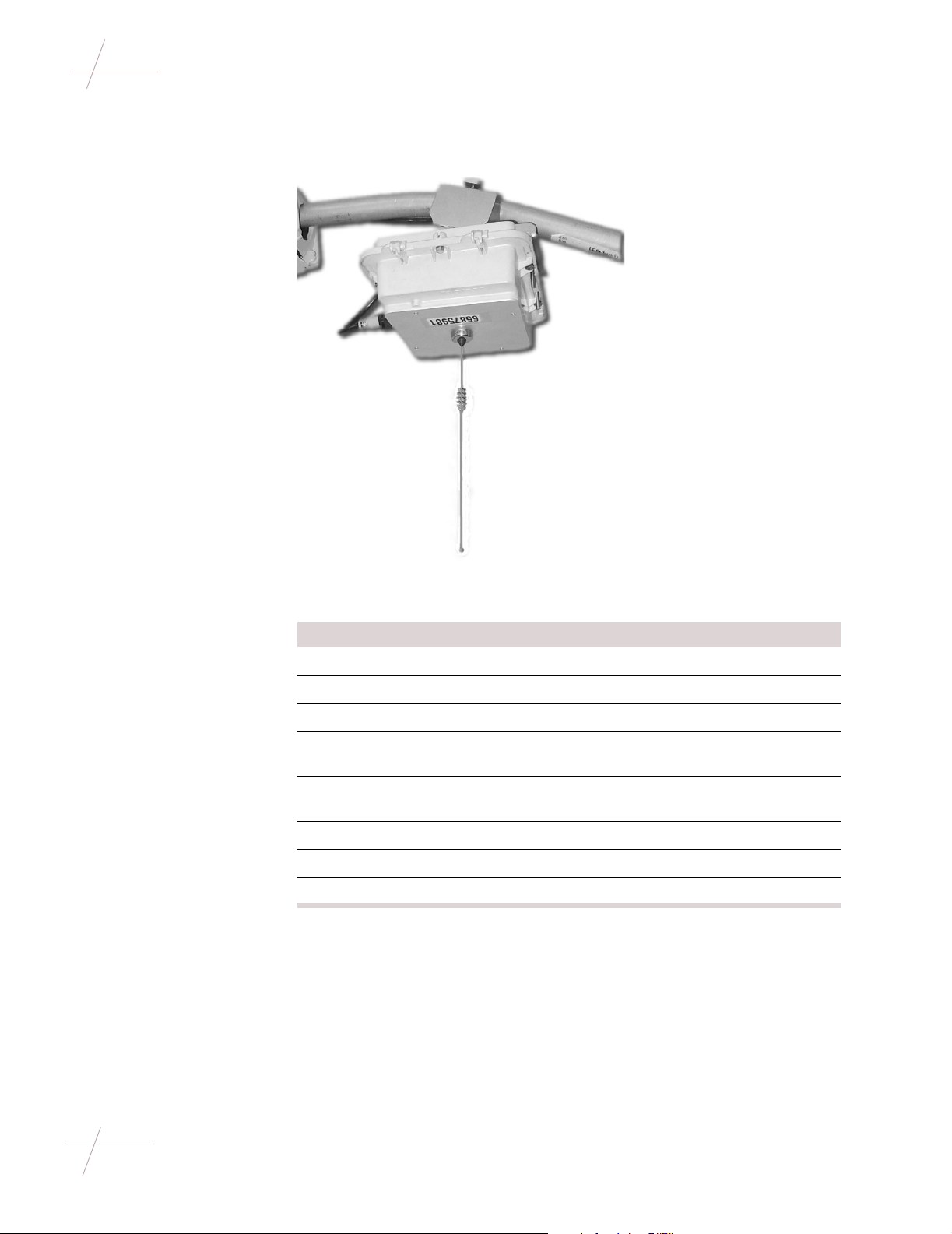
Overview A pole-mount repea te r mo unt s o n a streetlight davi t at least 6 inches be hi nd t he
lamp, which allows for cle arance to chang e the light bulb in the lamp.
Required Hardware and Tools
A pole-mount repeater installation requires the following tools and hardware:
• Adjustable Mounting Kit (CFG-003-002)
Adjustable Mounting Kit,
unassembled
Adjustable Mounting Kit, assembled and attached
to davit and repeater
DRAFT
Chapter 2 - Single-Channel Repeater Installation 7
TDC-0613-003b 03/06
Page 16

Installing Pole-Mount Repeaters
• 7/16-inch nut driver, wrench, or ratchet-wrench
• Inch-pound torque wrench with 7/16-inch and 1/2-inch sockets
• 1/2-inch wre nch
• Tie wraps (not supplied with mounting kit)
Earth Grounding Depending on the local re quirements for your uti lity company, you may need to
ground each repeater to earth ground. If you need to earth ground a repeater,
ground the case through one of the mounting screws that attach the repeater to
the pole using a groundin g cable in accordance with local utili ty company guidelines. The grounding cable is not supplied by Itron.
Wind Load Prior to insta lling a repe ater on a l ight pole, ensure tha t the weight a nd estimated
project area (EPA) of the repeater does not ex ceed the wind load and total weight
load of the light pole. The manufacturer of the light pole should provide wind
load and weight rating specifications.
Installing a SingleChannel Repeater
on a Davit
To install a repeater on a street light davit, follow the steps below.
Step Action
1
Attach the bottom plate of the mounting kit to the top of the repeater.
For this procedure, use the following items from the Adjustable
Mounting Kit:
• (4) small lock washers
• (4) small flat washers
• (4) 1 7/8-inch long bolts
• Bottom plate
2 Attach the adjustable bracket to the bottom plate. Use the following
items from the Adjustabl e Mounting Kit:
• (2) large lock washers
• (2) large flat washers
• (2) 1/2-inch nuts
• Adjustable bracket
• Bottom plate (attached to repeater)
IMPORTANT Do not completely tighten the nuts yet. The repeater ori-
entation will need to be adjusted once the kit is attached to the davit.
3 Partially bolt on e end of t he top pl ate ont o the adjustable bracke t of the
mounting kit. Leave the bo lt loose so that th e bracket can swi ng. When
you are ready to install the repeat er in its final posi tion, you wil l swing
the bracket across t he top of the davit and s ecure it. For thi s procedure,
use the following items from the Adjustable Mounting Kit:
• (1) small lock washer
• (1) flat washer
• (1) 3 1/4” bolt
8 Repeater Installation Guide
TDC-0613-003b 03/06
4 Place the antenna gasket over the antenna mount on the repeater.
DRAFT
Page 17

Installing Pole-Mount Repeaters
Step Action
5 Position the repeater beneath the davit, making sure that:
• The connectors of the repeater face the street lamp.
• The power cable can easil y extend be tween the power conne ctor
at the repeater and the photoelectric sensor.
• The repeater i s pla ced is at le ast a 3 in ches f rom the light fixt ure.
This allows the casing of the fixture to open completely, providing maintenance access when necessary.
• The bottom plat e of the mount ing kit is straight a long the si des of
the repeater lid and is securely attached.
• The groove on the adjustable bracket of the mounting kit aligns
with the davit.
• The repeater hangs straight down.
Top plate
Adjustable
bracket
3''
Bottom
plate
Connectors
6 Swing the unsecured end of the top plate of the mounting kit over the
davit and partially bolt it in place. Then torque both bolts to 40-inch
pounds.
IMPORTANT The two hex bolts must be torqued as specified to achie ve
the clamping force needed t o withstand 100 MPH. wind. If the bolt s are
under-torqued, the necessary clamping force may not be obtained. If
the bolts are over-torqued, the brackets may become overstressed and
clamping force may be reduced.
7 Use a voltmeter to verify that the unit has power. If power is not
present, the repeat er will not function. Make any corrections necessary
to provide power before continuing with the installation.
DRAFT
Chapter 2 - Single-Channel Repeater Installation 9
TDC-0613-003b 03/06
Page 18

Installing Pole-Mount Repeaters
Step Action
8 Provide power to the repeater. This can be done by either using a pho-
toelectric sensor or hard-wiring the repeater with power.
To install the photoelectric power adapter, use the steps below.
To hard-wire power to the repeater, skip to step 9.
a. Note the current o rientation of t he sensor window ( usually it f aces
north), so that you c an r est or e it to that orientation when you are
done.
b. Remove the photoelectric sensor.
c. Insert the repeate r photoe lectric power ad apter i nto the socket and
turn to lock it in place.
d. Re-insert t he ph otoele ctri c sensor int o the sock et on t he t op of the
power adapter.
e. Adjust the adapter to fa ce the photosensor window to its original
orientation by pulling up on the adapter housing and swiveling
the housing.
f. Plug the power cord into the 5-pin connector on the repeater.
g. Use tie-wraps as necessary to secure the cable away from the
repeater housing.
10 Repeater Installation Guide
TDC-0613-003b 03/06
Photoelectric power adapte r
Photoelectric sensor
DRAFT
Page 19

Installing Pole-Mount Repeaters
Step Action
9 To power the repeater when installing it on a pole without a photo-
electric sensor, you must strip the power cable with wire strippers and
connect the individ ual wires to the 120V and neut ral wir es on the p ole.
To hard-wire power to the repeater, follow the steps below.
a. Connect the unterminated end of the power cable to the power
source on the pole. The power cable is made up of two colored
wires: black and white. Connect these wires per the items bel ow:
* Black (wire color ) - Li ne si de (si gnal na me) - 5 (pin nu mber)
* White (wire color) - Neutral (signal name) 1 (pin number)
b. Wrap any excess cable around the davit or use tie-wraps (not
included) to secure the cable away from the repeater.
c. Connect the othe r end of the power cable to the 5- pin connector o n
the front of the repeater.
10 Before mounting the antenna, ensure the antenna gasket is seated
properly.
Attach the antenna. Be sure not to cross-thread the antenna when
installing it on the repeater. Attach the antenna on the bottom of the
repeater, tightening with a wrench until the antenna makes contact.
TIP To test whether the antenna makes contact, try to wiggle the
antenna. If it seems loose, continue tightening.
DRAFT
Chapter 2 - Single-Channel Repeater Installation 11
TDC-0613-003b 03/06
Page 20

Installing Sleeve-Mount Repeaters
Installing Sleeve-Mount Repeaters
Types of Sleeve-
Sleeve-mount repeater installation depends on the type of meter socket.
Mount Repeaters
Meter Socket Type Description
Ringless A ringless mounted meter installs under the meter
box lid, which is hinged at the top of the box.
Ringed A ringed meter installs on the outside of the meter
box and is secured with a meter seal ring.
Required Tools The following tools are necessary for sleeve-mount repeater installation:
• Tamper seals and associat ed meter insta llation/removal tools.
• Panduit Wave-Ty installation tool (optional). This tool cuts excess cable
and applies tension to the tension band.
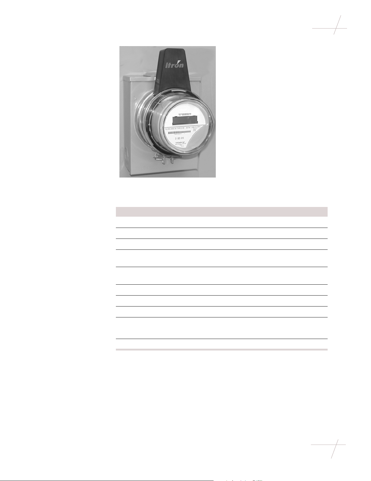
Installing on a Ringless Meter Socket
A ringless meter s ocket does not use a mete r seal ring between th e meter and th e
meter socket. Instead, the meter is secure d in the meter socket by a lid. To aid
installation on a ringless meter socket, the repeater antenna does not come
attached to the repeater. Attach it to the repeater in the following procedure.
To install a repeater on a ringless meter socket, follow the steps below.
IMPORTANT The followin g inst ructi ons sho uld be cons idere d s upplement al to
the meter installation and removal procedures for your utility. Follow all applicable procedures and regulations when performing meter installation.
Step Action
1 Remove tamper seals.
2 Verify that the service is compatible with the repeater.
3 Remove the meter socket lid.
4 Remove the meter from the socket.
5 Insert the repeater into th e socket.
12 Repeater Installation Guide
TDC-0613-003b 03/06
DRAFT
Page 21

Installing Sleeve-Mount Repeaters
Step Action
6 Replace the meter socket lid.
NOTE If needed, trim the breakaway rim on the repea ter sleev e using
diagonal cuts so that the socket lid will fit over the repeater.
7 Remove the protective label from the double- sided tape on the bott om
of the antenna (the antenna and antenna cover are one unit).
IMPORTANT Be careful to not damage or remove the tape.
8 Attach the antenna to the top of the sleeve.
IMPORTANT Ensure that it i s attached fo rward against t he shoulder and
centered on the flat area on the top of the sleeve.
Antenna/antenna
cover attached
DRAFT
Chapter 2 - Single-Channel Repeater Installation 13
TDC-0613-003b 03/06
Page 22

Installing Sleeve-Mount Repeaters
Step Action
9 Secure the tension band around the repeater and antenna, pulling to
tighten. Ensure that the back lip of the antenna is under the tension
band.
Antenna
(top view)
10 Tighten the tension band using a tension setting tool.
11 Clip off any excess material from the tension band.
12 Snap the met er into the repeater socket.
13 Attach and tighten the meter ring, making sure to catch the antenna
Tension band
cover lip under the ring band.
Antenna
cover lip
Meter ring
14 Repeater Installation Guide
TDC-0613-003b 03/06
14 Install a tamper seal in the ring band and on the meter socket lid.
DRAFT
Page 23

Installing Sleeve-Mount Repeaters
Installing on a Ringed Meter Socket
A ringed meter socket uses a meter sealing ring to secure the meter to the socket.
To install a repeater on a ringed meter socket, do the following steps.
Step Action
1 Remove tamper seals.
2 Verify that the service is comp atible with the repeater.
3 Remove the meter seal ring.
4 Pull the meter from the socket.
5 Insert the repeater sleeve into the meter socket.
Repeater
6 Remove the protective label from the double- sided tape on the bott om
of the antenna (the antenna and antenna cover are one unit).
IMPORTANT Be careful to not damage or remove the tape.
7 Attach the antenna/antenna cover unit to the top of the sleeve.
IMPORTANT Ensure that it i s attached fo rward against t he shoulder and
centered on the flat area on the top of the sleeve.
Antenna/antenna
cover attached
DRAFT
Chapter 2 - Single-Channel Repeater Installation 15
TDC-0613-003b 03/06
Page 24

Installing Sleeve-Mount Repeaters
Step Action
8 Secure the tension band around the repeater and antenna, pulling to
tighten. Ensure that the back lip of the antenna is under the tension
band.
Antenna
(top view)
9 Tighten the tension band using a tension setting tool.
10 Clip off any excess material from the tension band.
11 Secure a meter seal ring between the repeater and the meter socket.
12 Insert the meter into the repeater socket.
Tension band
Meter seal ring
16 Repeater Installation Guide
TDC-0613-003b 03/06
DRAFT
Page 25

Installing Sleeve-Mount Repeaters
Step Action
13 Attach the meter seal ring making sure to catch the antenna cover lip
under the ring band.
Catch cover lip
under ring
14 Replace the tamper seals.
DRAFT
Chapter 2 - Single-Channel Repeater Installation 17
TDC-0613-003b 03/06
Page 26

Installing Sleeve-Mount Repeaters
18 Repeater Installation Guide
TDC-0613-003b 03/06
DRAFT
Page 27

Chapter 3
Eight-Channel Repeater Installation
Getting Started
Overview This chapter shows you how to in stall an eight-channel repeater in the field. Your
repeater installa ti on process will depend on the type of r epeater (pole-mount or
decorative mount) and the installation location.
For more information, see:
• Installing Pole-Mount Repeaters on page 19
• Installing Decorative-Mount Repeaters on page 24
Installing Pole-Mount Repeaters
Overview A pole-mount repea te r mo unt s o n a streetlight davi t at least 3 inches be hi nd t he
lamp, which allows for cle arance to chang e the light bulb in the lamp.
Required Hardware and Tools
A pole-mount repeater installation requires the following tools and hardware:
• Adjustable Mounting Kit (CFG-003-002)
Adjustable Mounting Kit, unassembled
• 7/16-inch nut driver, wrench, or ratchet-wrench
• Inch-pound torque wrench with 7/16-inch and 1/2-inch sockets
DRAFT
Chapter 3 - Eight-Channel Repeater Installation 19
TDC-0613-003b 03/06
Page 28

Installing Pole-Mount Repeaters
• 1/2-inch wre nch
• Tie wraps (not supplied with mounting kit)
Earth Grounding Depending on the local re quirements for your uti lity company, you may need to
ground each repeater to earth ground. If you need to earth ground a repeater,
ground the case through one of the mounting screws that attach the repeater to
the pole using a groundin g cable in accordance with local utili ty company guidelines. The grounding cable is not supplied by Itron.
Wind Load Prior to insta lling a repe ater on a l ight pole, ensure tha t the weight a nd estimated
project area (EPA) of the repeater does not ex ceed the wind load and total weight
load of the light pole. The manufacturer of the light pole should provide wind
load and weight rating specifications.
Installing an EightChannel Repeater
on a Davit
T o install a n eight-channel repeater on a s treet light da vit, follow the steps below .
Step Action
1 Attach the bottom plate of the mounting kit to the top of the repeater.
For this procedure, use the following items from the Adjustable
Mounting Kit:
• (4) small lock washers
• (4) small flat washers
• (4) 1 7/8-inch long bolts
• Bottom plate
2 Attach the adjustable bracket to the bottom plate. Use the following
items from the Adjustabl e Mounting Kit:
• (2) large lock washers
• (2) large flat washers
• (2) 1/2-inch nuts
• Adjustable bracket
• Bottom plate (attached to repeater)
IMPORTANT Do not completely tighten the nuts yet. The repeater ori-
entation will need to be adjusted once the kit is attached to the davit.
3 Partially bolt on e end of t he top pl ate ont o the adjustable bracke t of the
mounting kit. Leave the bo lt loose so that th e bracket can swi ng. When
you are ready to install the repeat er in its final posi tion, you wil l swing
the bracket across t he top of the davit and s ecure it. For thi s procedure,
use the following items from the Adjustable Mounting Kit:
• (1) small lock washer
• (1) flat washer
• (1) 3 1/4” bolt
20 Repeater Installation Guide
TDC-0613-003b 03/06
4 Place the antenna gasket over the antenna mount on the repeater.
DRAFT
Page 29

Installing Pole-Mount Repeaters
Step Action
5 Position the repeater beneath the davit, making sure that:
• The connectors of the repeater face the street lamp.
• The power cable can easil y extend be tween the power conne ctor
at the repeater and the photoelectric sensor.
• The repeater i s pla ced is at le ast a 3 in ches f rom the light fixt ure.
This allows the casing of the fixture to open completely, providing maintenance access when necessary.
• The bottom plat e of the mount ing kit is straight a long the si des of
the repeater lid and is securely attached.
• The groove on the adjustable bracket of the mounting kit aligns
with the davit.
• The repeater hangs straight down.
3''
Top plate
Adjustable
bracket
Bottom
plate
Connectors
6 Swing the unsecured end of the top plate of the mounting kit over the
davit and partially bolt it in place. Then torque both bolts to 40 inchpounds.
IMPORTANT The two hex bolts must be torqued as specified to achie ve
the clamping force needed t o withstand 100 MPH. wind. If the bolt s are
under-torqued, the necessary clamping force may not be obtained. If
the bolts are over-torqued, the brackets may become overstressed and
clamping force may be reduced.
7 Use a voltmeter to verify that the unit has power. If power is not
present, the repeat er will not function. Make any corrections necessary
to provide power before continuing with the installation.
DRAFT
Chapter 3 - Eight-Channel Repeater Installation 21
TDC-0613-003b 03/06
Page 30

Installing Pole-Mount Repeaters
Step Action
8 Provide power to the repeater. This can be done by either using a pho-
toelectric sensor or hard-wiring the repeater with power.
To install the photoelectric power adapter, use the steps below.
To hard-wire power to the repeater, skip to step 9.
a. Note the current o rientation of t he sensor window ( usually it f aces
north), so that you c an r est or e it to that orientation when you are
done.
b. Remove the photoelectric sensor.
c. Insert the repeate r photoe lectric power ad apter i nto the socket and
turn to lock it in place.
d. Re-insert t he ph otoele ctri c sensor int o the sock et on t he t op of the
power adapter.
e. Adjust the adapter to fa ce the photosensor window to its original
orientation by pulling up on the adapter housing and swiveling
the housing.
f. Plug the power cord into the 5-pin connector on the repeater.
g. Use tie-wraps as necessary to secure the cable away from the
repeater housing.
22 Repeater Installation Guide
TDC-0613-003b 03/06
Photoelectric power adapte r
Photoelectric sensor
DRAFT
Page 31

Installing Pole-Mount Repeaters
Step Action
9 To power the repeater when installing it on a pole without a photo-
electric sensor, you must strip the power cable with wire strippers and
connect the individ ual wires to the 120V and neut ral wir es on the p ole.
To hard-wire power to the repeater, follow the steps below.
a. Connect the unterminated end of the power cable to the power
source on the pole. The power cable is made up of two colored
wires: black and white. Connect these wires per the items bel ow:
* Black (wire color ) - Li ne si de (si gnal na me) - 5 (pin nu mber)
* White (wire color) - Neutral (signal name) 1 (pin number)
b. Wrap any excess cable around the davit or use tie-wraps (not
included) to secure the cable away from the repeater.
c. Connect the othe r end of the power cable to the 5- pin connector o n
the front of the repeater.
10 Before mounting the antenna, ensure the antenna gasket is seated
properly.
Attach the antenna. Be sure not to cross-thread the antenna when
installing it on the repeater. Attach the antenna on the bottom of the
repeater, tightening with a wrench until the antenna makes contact.
TIP To test whether the antenna makes contact, try to wiggle the
antenna. If it seems loose, continue tightening.
DRAFT
Chapter 3 - Eight-Channel Repeater Installation 23
TDC-0613-003b 03/06
Page 32

Installing Decorative-Mount Repeaters
Installing Decorative-Mount Repeaters
Overview Decorative-mount repeaters are designed to “blend in” more with their sur-
roundings. These repeaters are typically installed in developments, residential
areas, or other areas where an empha sis is placed on the appearance of the
device.
Installing a Decorative-Mount Repeater
Installing a decorative-mount repeater is a relatively simply process. To install
this type of repeater, follow the steps below.
Step Action
1 Remove the existing photo-electric sensor from the decorative
lamppost. Be sure to note the orientation of sensor window (this typically faces north).
NOTE The existing sensor is no longer needed. The deco rative repeater
has a built-in photo-electric sensor.
2 Slide the rubber seal over the base of the repeater , as shown below . The
seal should lay just below the photo-electric sensor window on the
repeater.
24 Repeater Installation Guide
TDC-0613-003b 03/06
Photo-electric
sensor window
3 If necessary, rotate the socket so that the photo-electr ic sensor window
Rubber seal
will be oriented properly (typically facing north) when the repeater is
installed. If a photo -electr ic sens or was pr eviously instal led, the sock et
should already be oriented properly.
DRAFT
Page 33

Installing Decorative-Mount Repeaters
Step Action
4 Attach the repeater to the top of the lamppost. Be sure to align the
prongs on the repeater with the correspondi ng sockets on the lamppos t.
5 Slide the rubber seal down to the top of the lamppost.
Verify that a tight seal around the entir e repea ter has been cre ated; this
will keep water from intruding into the repeater and top of the
lamppost.
DRAFT
Chapter 3 - Eight-Channel Repeater Installation 25
TDC-0613-003b 03/06
Page 34

Installing Decorative-Mount Repeaters
Step Action
6 When you have finished, your lamppost should look similar to the
example below.
26 Repeater Installation Guide
TDC-0613-003b 03/06
DRAFT
 Loading...