

Page 1

ChoiceConnect
CCU 100 and Repeater 100 Installation Guide
Page 2

Identification
CCU 100 and Repeater 100 Installation Guide
10/25/2010 TDC-0971-000
Copyright
© 2010 Itron, Inc. All rights reserved.
Confidentiality Notice
The information contained herein is proprietary and confidential and is being provided subject to the condition that (i) it be held in confidence except t o the extent required otherwise by
law and (ii) it will be used only for the purp oses described herein. Any third party that is given access to this information shall be similarly bou nd in writing .
Trademark Noti ce
Itron is a registered trad emark of Itron, Inc.
All other product names and logos in this documentation are used for identification purposes only and may be trademarks or registered trademarks of their respective companies.
Suggestions
If you have comments or suggestions on how we may improve this documentation, send them to TechnicalCommunicationsManager@itron.com
If you have questions or comments about the software or hardware product, contact Itron Technical Support:
Contact
• Internet: www.itron.com
• E-mail: support@itron.com
• Phone: 1 877 487 6602
Compliance
This device comp lies with Part 15 of the FCC Rules. These limits are d esigned to provide reasonable protection against harmful interference in a residential insta llation. O peration is
subject to the following two conditions:
• This device may not cause harmful interference.
• This device must accept any interference that may cause undesirable operation.
This device must be permanent ly mounted such that it retains a distance of 22.7 centimeters (9 inches) from all persons in order to comply wit h FCC RF exposure levels.
USA, FCC Class B - Part 15
This equipment has been tested and found to comply with the limits for a Class B d igital device, pursuant to Part 15 of the FCC Rules. These limits are d esigned to provide reasonable
protection against harmful interference in a res identia l installation. This equipment generates, uses, and can radiate radio frequency energ y and, if not installed and used in accord ance
with the instructions, may cause harmful interference to rad io communications. However, there is no guarantee that interference will not occur in a particular installation.
If this equipment does cause harmful interfere nce to radio or television rec eption, which can be determined by turning the equipment off and on, the user is encouraged to try to correct
the interference b y one or more of the following measures:
• Reorient or re locate the receiving antenna.
• Increase the separation between the equipme nt and receiver.
• Connect the equipment into an out let on a circuit different from that to which the receiver is conn ected.
• Consult the dea ler or an experienced radio or TV technician for he lp.
This equipment has been tested and found to comply with the limits, pursuant to Part 15 of the FCC Rules. These limits are designed to provide reaso nable protection against harmfu l
interference in a residentia l installation. Operation is subject to the following conditions:
• This device may not cause interfer ence.
• This device must accept any interference that may cause undesired operatio n of the device.
CANADA, DOC ICES-003
This digital apparatus does not exceed the class B limits for radio noise emissions from dig ital apparatus set out in the Radio Interference Reg ulations of the Canadian Department of
Communications, standard ICES-003.
This equipment complies with policies RSS-21 0 and RSS-GEN of the Industry Canada rules.
Operation is subject to the following two conditions: (1) this device may not cause interfer ence, and (2) this device must accept any interference, including interference that may cause
undesired operation of the device.
Avis de conformite aux normes du Ministere des Communications du Canada.
Le present apparei l numerique n em et pas de bruits radioelectriques depassant les limites applicab le aux appareils numeriques classe B prescrites dans le Reglement sur le brouillage
radioelectriq ue edicte par le Ministere des Communications du Canada, NMB-003.
Caution ELECTROMAGNETIC COMPATIBILITY
Use only approved acce ssories with this equipment. I n general all cables must be
high quality, shi elded, and correctly terminated. Unapproved modifications or
operation beyond or in co nflict with these instructions for use, may void
authorizati on by the authorities to operate the equipment.
Page 3

Proprietary and Confidential
Contents
Before You Begin........................................................................................................... v
Documentati on Conventions ........................................................................................................... v
Related Document s ....................................................................................................................... vi
Chapter 1 CCU/Repeater Basics ................................................................................. 1
CCU Configuration .........................................................................................................................1
CCU/Repeater Com ponents ...........................................................................................................2
CCU/Repeater Modul e .........................................................................................................2
Remote GPS/WAN Antenna System ....................................................................................3
Endpoint Ant enna .................................................................................................................5
Chapter 2 Planning a CCU/Repeater Installation ....................................................... 7
Installation Profiles .........................................................................................................................7
Siting CCUs/Repeater s ..................................................................................................................8
Propagation Study and CCU/Repeater Site Sel ection ...........................................................8
GPS and WAN Coverage .....................................................................................................8
AC Service Requir em ents ....................................................................................................9
External Ether net Connections .............................................................................................9
Remote Endpoint Ant enna Pl acement ..................................................................................9
Grounding the Antenna S yst em .......................................................................................... 10
Lightning Arrestor ......................................................................................................................... 11
AC Mains Power .......................................................................................................................... 12
DC Mains Power .......................................................................................................................... 12
Materials Not Pr ov ided by Itron..................................................................................................... 13
Coaxial Cable ..................................................................................................................... 13
Antenna Connectors ........................................................................................................... 14
Mounting Hardware ............................................................................................................ 15
Chapter 3 Installing the CCU/Repeater ..................................................................... 17
Installation Overview .................................................................................................................... 17
Attaching the GPS/WAN Remote Antennas .................................................................................. 18
Attaching the Dir ect M ount Endpoint Antenna ............................................................................... 19
Attaching the CCU/Repeater ........................................................................................................ 21
Mounting Hardware ............................................................................................................ 21
Pipe Mount ......................................................................................................................... 22
Pole Mount ......................................................................................................................... 24
Wall Mount ......................................................................................................................... 26
Davit Arm Mount ................................................................................................................ 27
Connecting Cabl es ....................................................................................................................... 29
Installing the Battery ..................................................................................................................... 30
Providing Power ........................................................................................................................... 32
AC Mains Non-Remote Installation Diagram ................................................................................. 33
Tower Installation ......................................................................................................................... 33
CCU 100 and Repeater 100 Installation Guide iii
Page 4

Contents
Proprietary and Confidential
Tower Installation Overview ................................................................................................ 34
TCU Components............................................................................................................... 35
AC Tower Install ation Diagram ........................................................................................... 38
Solar Powered Instal lation ............................................................................................................ 39
Solar Installation Overview ................................................................................................. 39
Solar Wiring Diagram ......................................................................................................... 40
Solar Installation Diagram................................................................................................... 41
Chapter 4 Battery Care and Replacement ................................................................ 43
Shipping Requirem ents ................................................................................................................ 43
Battery Storage and Char ging ...................................................................................................... 44
Long-Term Storage ............................................................................................................ 44
State of Charge .................................................................................................................. 45
Charge the Batter y ............................................................................................................. 45
Battery Service Life ...................................................................................................................... 46
Calendar Lif e ...................................................................................................................... 46
Preventative Maintenance .................................................................................................. 46
Replacing the Integrated Battery .................................................................................................. 47
Appendix A Detailed CCU/Repeater Specifications................................................. 49
CCU/Repeater Dim ensi ons and Weight ........................................................................................ 49
Antenna Specifications - 100 ........................................................................................................ 50
Environment al S pecifications ........................................................................................................ 51
Transmitter ................................................................................................................................... 51
CCU/Repeater Power Operat ing Range ....................................................................................... 51
Battery Pack................................................................................................................................. 52
Appendix B Status and Diagnostics ......................................................................... 53
Status Indicator ............................................................................................................................ 53
Diagnostic Port ............................................................................................................................. 54
Performing an Ant enna S weep Test ............................................................................................. 55
Index ............................................................................................................................. 57
iv CCU 100 and Repeater 100 Installation Guide
Page 5
Proprietary and Confidential
Convention
Example
monospace
monospace
upload.dat
Before You Begin
Important Proper i nstallation of the CCU/Repeater ensures trouble-free operation
of the I tr on Fixed Network s yst em. T he installation of bot h the collect or a nd
repeater must be done by profes si ona l inst al lers.
Documentation Conventions
This document uses the following conventions.
Key presses are in bold. Click OK to finish.
Menu paths are in bold. Select Start > File > Save As.
Computer co mma nds to b e ty pe d by the use r
are in a
File names are in a
Hypertext links are blue. See the Copyright page for the contact information.
Note A note indicates neutral or positive information that stresses or
supplements important points of the main text. A note supplies information that
may apply onl y in special cases.
Caution A caution advises users that failure to take or avoid a specified action
could result in a loss of data.
Warning A warning advises users that f ailur e to take or avoid a specified
action could resul t in physical harm to the user or the hardware.
font.
font. The data is uploaded to the
At the C: promp t, ty pe cd itr on/b in
file
Tip A tip helps users apply the techniques and procedures described in the text
to their specific needs. A tip is not essential to the basic understanding of the text.
CCU 100 and Repeater 100 Installation Guide v
Page 6

Before You Begin
Proprietary and Confidential
Related Documents
For more information about CCUs/Repeaters and the Fixed Network, see the following:
• Collector Configuration Application v4.0 User Guide
Fixe d Networ k system admi nistrators must us e this document to proper ly configure
CCU 100s before they are installed in the field.
• Network Collection Engine v4.0 User Guide
• Motorola R56 Manual- Standards and Guidelines for Communication Sites
Available from Motorola. This ma nual illust ra tes industry best prac tices for mounting
and groundi ng antenn a systems, and routing antenn a cables into buildings . Use this
guide as a ref erence when r e motely mounting t he end point ante nna.
vi CCU 100 and Repeater 100 Installation Guide
Page 7

Proprietary and Confidential
C
HAPTER
1
CCU/Repeater Basics
The CCU 100 (also known as a cell control unit or collector) and the Repeater 100 ar e
configurable for different installation locations, including:
• On a water or communications tower.
• On a pole (s uch as an elect ricit y or light pole ) .
• On a wall ( indoo r or outdoor).
• On a pipe (between 2 and 3.5 inches in di am eter).
Int e gra ted mount ing and coupling bracket s secure the device i n high wind s and under heavy
ice loa ds .
The C CU 100 also supports a n optiona l solar pow er kit. K its ar e size d by peak s un hour
calc ulation s whi ch vary regi onally ac ross the country. T he kit includes solar panels and a
large battery backup unit. Size and weights vary by package type (based on peak sun
hours).
A CCU/Repeater consists of a number of components in a single weatherproof device.
Electrical components are encased in a plast ic encl osure tha t provi de s double insulation and
a high leve l of saf et y for the i nstaller.
Caution Only authorized It r on personnel may open the CCU or Repeater.
Unauthorized acce ss to the m odule voids the warranty.
Modificati on of t his device voids the warranty and coul d cause non-com pliance with
FCC rules.
CCU Configuration
A Fixed N etwork sys tem admi nistrator must conf igure each CCU 100 bef ore it c an be
installed in the field. V erify with your supervis or or the system adm inistrator that a ll CCUs
ar e c onfigured bef ore yo u attempt to inst all t hem.
Please see the Coll ector Configuration Application v4.0 User Guide for m ore i nformat i on.
CCU 100 and Repeater 100 Installation Guide 1
Page 8
Chapter 1 CCU/Repeater Basics
Proprietary and Confidential
CCU/Repeater Components
The CCU 100 and Repeater 100 come in two basic configura tions , non-remote a nd remote.
The re m ote CC U /R epeater configurati on repl aces the internal a n te nnas wi th external
ant e nna connector s allowi ng both GP S a nd W AN antennas t o be mou nted in a r e m ote
locati on. I n the case of the Repeat er 100 , only an externa l GPS connection is provided; a
WAN modem is not present in a repeater. Both non-remote and remote configurations allow
for remotely mounting the endpoint antenna by removing the antenna from the unit and
at tachi ng it to a r e mote a ntenna mounting plate.
Sinc e the CCU/ Repeat er ma y be installed in an outdoor e nvironment, each component of
the CC U /R epeater i s weat her-tight and can withstand wind re quirements i n excess of 100
MPH.
Note When determining the configuration of the CCU/Repeater, be sure to review
the Itron CCU 100 Ordering Guide or the Itron Repeater 100 Ordering Guide for
specific part numbers, cable lengths, and various options for the components.
CCU/Repeater Module
The CCU/Repeater opera tes in t he 902 to 928 MHz fre quenc y range . The C CU/ Repea ter
cas e houses the bac kup battery, GP S receiver , opt ional WAN radio, process ing boar d and
endpoi nt ra dio. The antennas for the radios c an be e i ther inter nally connected or r emot e ly
connected, depending on the CCU/Repeater configuration.
Caution Only authorized It r on per sonnel m ay open the CCU/Repeater. Unauthorize d
access to the modul e voi ds the warrant y.
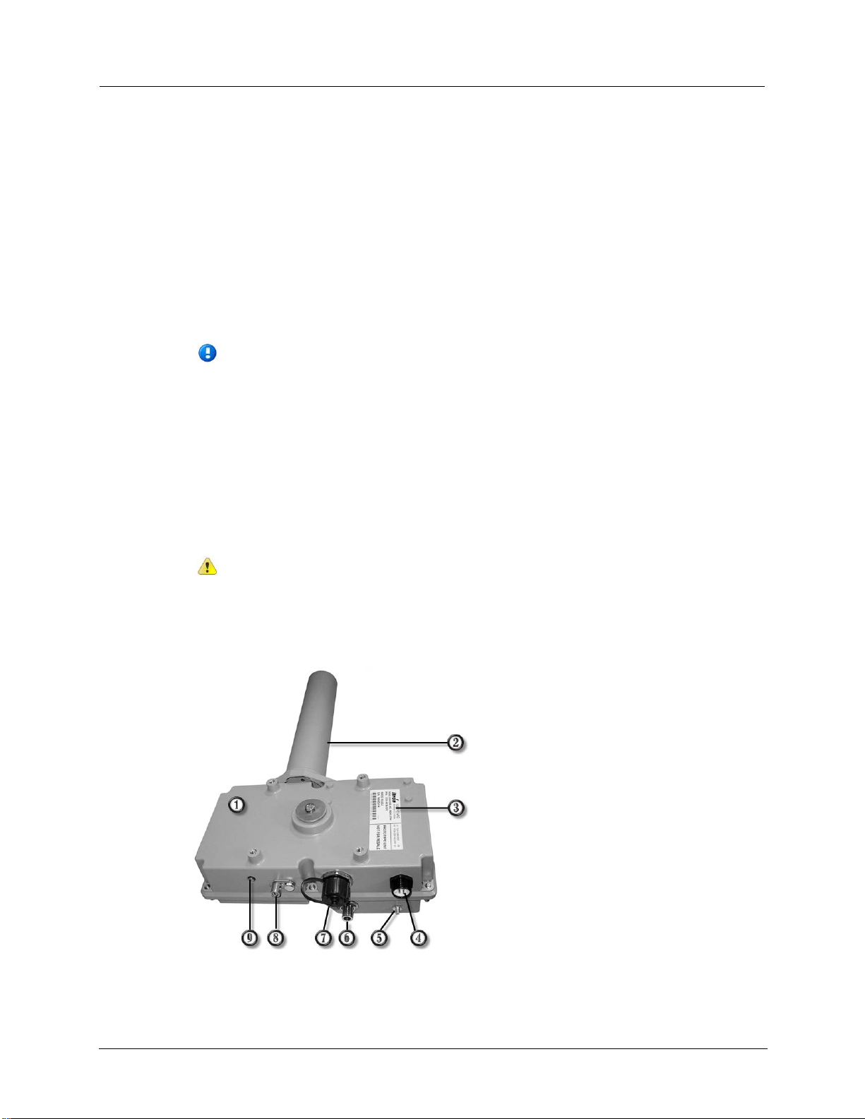
An example of the remote CCU is shown below; the component connections are described
in the following table.
2 CCU 100 and Repeater 100 Installation Guide
Page 9

CCU/Repeater Components
Proprietary and Confidential
Item
Description
CCU/Repeater module
Proce ss es data fro m t he ante nn as an d relays it on to t he F ixe d Ne tw o rk App licatio n So f tw are. O n ly
CCU and the Re peate r and s hould b e a ttached to earth ground
1
authorized Itro n pe rsonne l m ay ope n this mo dule.
Endpoint antenna
2
This 900MHz antenna receives messages from and sends messages to endpoints and repeaters in the
network. The connection for this antenna is a Type N female.
CCU/Repeater label
3
Display s the colle cto r identif icat ion nu mbe r, mode l numb er, a nd ot her assoc iate d info rmat ion.
Pow er co nne cto r
4
Supplies pow er to the CCU/Repeater module. AC mains, DC, or solar power options are available. A
three pin cable connects the CCU/Repeater to the mains supply. A two pin cable connects the
CCU/Repeater to a DC supply. A five pin cable connects the CCU/Repeater to the solar system.
Remo te GP S an t enna co n necto r
5
This female SMA connector is only on the remote CCU/Repeater. Use this connector when remotely
mounting the GPS a ntenna.
Remote WAN antenna connector
6
This female N connector is only on the remote CCU. Use this connector when remotely mounting
the WAN antenna.
Ethernet
7
Connects the CCU/Repeater to the Ethernet backhaul. Also used to connect the CCU/Repeater to a
router for initial collector setup. Mating weatherproof cables are available from Itron. These cables are
sealed industrial ethernet circular IP67 connectors (CONEC)
Note A waterproof cap seals the Ethernet port from the elements in the field. Be sure to securely
attach the cap once the collector is installed.
Ground lug
8
The ground lug is provided on both the
according to local regulations. This ground helps protect the internal circuitry from high voltage
transient events. The ground lug accepts AWG minimum wire size 14, and maximum wire size 4.
Status indicator
9
This indicator displays the current operational status of the CCU/Repeater. See Status Indicator on
page 53 for more information.
(Not shown) Battery door
*
Removal of this door allows access to the replaceable battery pack.
Remote GPS/WAN Antenna System
The r e m ote CCU/Repeater confi guration uses a G PS/WAN antenna kit that is connec ted to
the CC U /R epeater by one or two separate pieces of coaxial cable.
• The W AN antenna is only c onnec ted in CCU ins tall ations that us e a wide a rea
net w ork backhaul system.
• The GPS antenn a is used in all deployment s of this syst em.
The a ntennas must be inst alled i n a locati on that allows r eception of GP S and W AN signals .
CCU 100 and Repeater 100 Installation Guide 3
Page 10
Chapter 1 CCU/Repeater Basics
Proprietary and Confidential
Itron recom mends us ing a handhel d G PS unit to ver ify t hat your G PS ant e nna mounting
Item
Description
location can receive a signal from at least three satellites.
If you are using a GPRS WAN backhaul, Itron recommends testing the GPRS antenna at
your desi red installation t o ensure t hat GPRS ser vi ce is ava il able at that loca tion.
For m ore information, see G PS and WAN Coverage on page 8.
Caution The GPS antenna must be oriented vertically when installed, and it must
have an unobstructed v iew of the sky to properly receive a GPS signal.
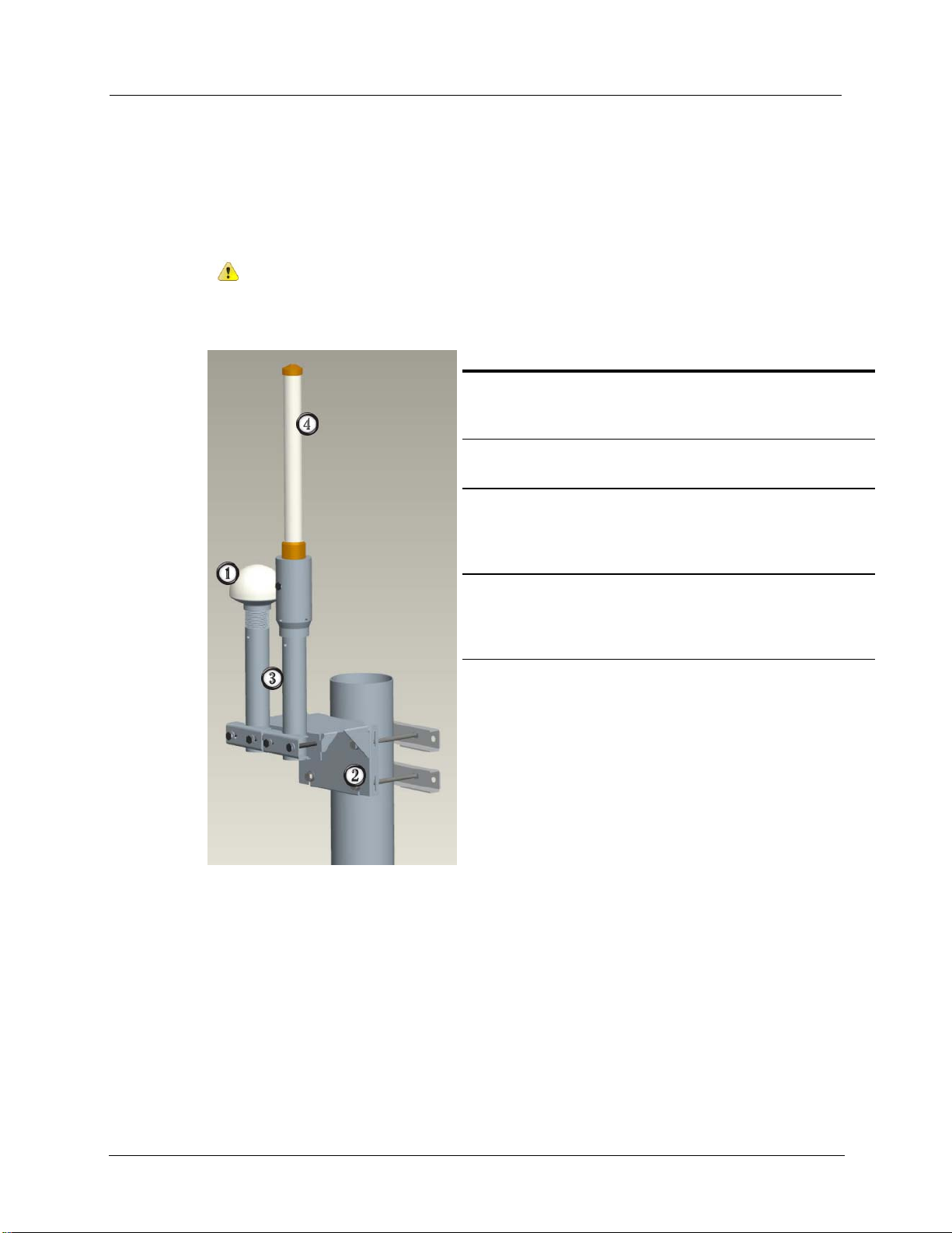
The GPS/WAN antenna syst e m is shown below.
1 GPS antenna
Receives GPS data from orbiting satellites. The cable
connection on the bo tto m o f this ante nn a is TN C Fe ma le .
2 Mounting bracket
Attaches the antenna to your desired mounting location.
3 Antenna masts
Provide support for the GPS and WAN antennas. Cables for
each ante nna are route d t hrough t he masts. Clamps o n the front
of the mounting bracket secure the masts.
4 WAN antenna (CCU only)
Provides the wide-area network (WAN) signal for the CCU.
The Repeater does not use this antenna. The cable connection
on the bo tto m o f t his a nten na is N Fe male .
4 CCU 100 and Repeater 100 Installation Guide
Page 11

CCU/Repeater Components
Proprietary and Confidential
Endpoint Antenna
The Endpoint antenna tra nsmits a nd receives da ta m es sage s fr om endpoints and rep eat ers in
the network .
There are fi ve possible antennas ( two di rect atta c hed antennas and three remote a ntennas )
tha t may be use d for the end point r adio link .
• A standard verti cally or horizontally polariz ed antenna that is di rectly att ached to the
CCU/Repeater.
• A standard verti cally or horizontally polariz ed antenna that can be connected
remotely, in place of the dire ct a tta c hed solution.
• A high-gain ve rti c ally pol ar ized remote antenn a (8.15dBi) that is mounted r e m otely in
place of the direct attached solution. This a ntenna is only approve d f or the Tower
CCU w i th proper cable loss t o meet FCC regu lations.
• Remote antennas must be properly grou nded during i nst alla tion. Whe n a r e m ote
ant e nna is use d, a li ghtning arr estor is s upplied for this purpo se.
• The r e m ote antenna' s maximum allowed installation hei ght above ground is 100 f eet.
Installation heights a re deter mined by RF propagation st udies by Itron systems
engineering. If additional height is needed for the antenna, the tower version of the
CCU is recommended.
• Coaxial cable used to connect the endpoint antenna to the CCU/Receiver must be
prope r l y grounded. Se e L igh tning Ar r es t or on page 11 f or more informat ion.
• All coaxial cable connections must be properly weather-proofed per industry
st andards , un les s othe rwis e spec i fied. If the CC U/R epeater is i nstalled indoor s, only
the connections located outside need to be weather-proofed.
When the CCU/ Repeat er is ordered w ith a remote a ntenna kit, s ome assoc i ated mounting
har dware is i ncluded. Coaxial cables for the remote antennas a re not incl ude d in the kit.
These cables must be provided by the install er. Pl ease s ee Coaxia l Cabl e on page 13 for
coaxial cable specifications.
For m ore information, see :
• Ant e nna Spec ifications on page 50
• Remote E ndpoint Antenna Plac ement on page 9
• Grounding the Remote Antenna System on page 10
CCU 100 and Repeater 100 Installation Guide 5
Page 12

Chapter 1 CCU/Repeater Basics
6 CCU 100 and Repeater 100 Installation Guide
Proprietary and Confidential
Page 13

Proprietary and Confidential
Location
Description
inches in d iame te r) . T his type of i nst alla tio n ty pic ally oc cu rs on the tops o f
C
HAPTER
2
Planning a CCU/Repeater Installation
This c h apter desc ribes how to prepare for a CCU/ repeater i n st allation.
Installation Profiles
The CCU/Repeater can be installed in a variety of configurations and locations .
Depending on the installation location, the CCU or Repeater components may be installed
all i n the s ame pl ac e (as an integr ated soluti on), or the ant e nnas may be installed remotely
fr om the C CU/ Repeater (as a dist ributed solution).
For example, the CCU/Repeater can be installed at the base of a water tower, the
GPS/WAN ante nna syst e m c an b e m ounted up to 12 feet away for opti mum reception , a nd
the e ndpoint ant e nna can be placed a t the t op of the water t ower .
The following profiles have been identified for CCU installation .
Utility po le The CCU/Repeater is installed on a utility pole. The CCU/Repeater should
Light pole The CCU/Repeater is installed on either a light pole or the davit arm that
Outdoor wall or pipe with remote
antenna
Indoor wall o r pi pe w ith remote
antenna
Pipe The CCU/Repeater is secured to a pipe or fence railing (from 2 to 3.5
be mounted as high as possible on the pole for optimum reception.
extends from t he light pole . The CCU /Repe ater s hould b e mo unted as hig h
as possible on the pole for optimum reception.
The CCU/Repeater is installed on an outside wa ll o r pipe wit h t he e ndpoi nt
antenn a remo tely mounte d to ac hiev e the max imu m elev atio n and
reception.
The CCU/Repeater is installed inside an equipment room with the endpoint
antenna remotely (and externally ) mo u nted to ac hie v e ma xi mu m elevatio n
and reception. The WAN (or other digital cellular) and GPS antenna are
remotely (and externally) mounted to provide acceptable coverage.
For more information on these various profiles, as well as the Itron-recommended profile,
see Cha pter 3, Installi ng the CCU/Repeater on page 17.
CCU 100 and Repeater 100 Installation Guide 7
water towers.
Page 14

Chapter 2 Planning a CCU/Repeater Installation
Proprietary and Confidential
Siting CCUs/Repeaters
CCUs/Repea ters are inst all e d in t he field on a va riety of s urfaces, such as wooden or meta l
walls , metal pip es , fence rail ing, and utility poles.
When det ermini ng where to pla ce the CCU/Repea ter, t here are four primary consi der ation s:
• Siting for optimum RF reception.
• Sit ing for optimum GPS a nd/or W AN reception.
• Availability of Ethernet connection (if required).
• Availability of power connection.
• Availability of a structure or loc ation that can physically support the CCU/Repeater
and it s mounting hardw ar e.
Caution Always ensure that you have permission to install a CCU/Repeat er at
your chosen site prior to beginning installation.
Propagation Study and CCU/Repeater Site Selection
Pr i or to installing a C CU/Repeater in the field, consult with Itr on to perf orm a propagation
study. This stud y:
• Evaluates the quantity and t ypes of endpoints in t he network.
• Assesses environmental and geographical considerations related to CCU/Repeater
installation.
• Opti m izes C CU/ Repeat er place m ent in the network for the best pos sibl e reception.
• Helps influ e nce the p hysical a nd st ruc tural imp licati ons of mounting a C CU/R epeater
to a given surf ace.
Once the propagation study is complete, you can determine exactly where to install
CCUs/Repea ters and what they wil l be mou nted to.
GPS and WAN Coverage
CCUs/Repeaters must be installed in loca tion s where a GPS si gnal is st rong and cons ist e nt.
If WAN is being used as the com muni c ations bac khaul for the network, a strong and
consistent WAN s igna l is re quired a s well (for CCUs only). If t he sign al is too weak, or its
availability fluctuates, the CCU/Repeater can not gather accurate date/time information or
com municate with the Fix ed Network softwa re.
Itron recom mends us ing a handhel d G PS unit to ver ify t hat your CCU/ Repeater or remote
GPS ante nna mount ing l oca tion can r e cei ve a s i gnal f rom a t least three satellites.
If you are using a GPRS WAN backhaul, Itron recommends testing the CCU or remote
GPRS ant e nna at your desired ins tallation to ens ure that GPRS service is availa ble a t that
location.
8 CCU 100 and Repeater 100 Installation Guide
Page 15

Sit ing C CUs/Repeaters
Proprietary and Confidential
To ensure the best poss ibl e s ignal, avoid ins tal li ng t he CC U/R epeater o r the r emote
ant e nnas i n the f oll owi ng ways:
• Adjace nt to or between tal l buildings, signs, tower s, or bri dges.
• Near swaying limbs, bra nc hes, or cabl es that could strike and damage the antenna.
• Between, beneath, or near highway overpas ses, eleva ted train platf orms, or tunnels.
• Near objects or devices attached to the same pole.
• Wit hin 500 feet of high power ra dio fr eque ncy (RF) transmit ters (such as paging
tra nsmitt ers, c e llular tra nsmitters, and municipal com municati on s transmitters ).
• Near pot e ntial broadband sources of radiated R F energy (such as power line
transformers, RADAR transmitter s, c el l ular a ntennas, and ne on or fluorescent sign s).
• Inside metal enclosures (the antenna will not communicate if surrounded by metal) or
inside a building. The CCU/Repeater can be installed in a building or other metal
enclosure, but the antennas must be installed remotely.
Warning! Before installing a CCU/Repeater near or on the sam e pole as a
transformer , consul t the National Electrica l S afety Code (NESC), local utilities,
municipalities, and cable and telephone companies for recommended distances
from transform er s and power lines.
AC Service Requirements
A 90 to 265 VAC 10A power source is required at the installation site for the
CCU/Repea ter, unless yo u a re using t he DC C CU/Repe at er or the solar CCU/R epeat er. Fo r
mor e i nformation on these options, see Mains Power Installation Profiles on page 12 or
Sola r P ow er Ins tall ation P rofiles on page 39.
External Ethernet Connections
If the Ethernet connection is used as the communications backhaul, the CC U instal lation
site must have Ethernet access. Also, be sure to use weatherproof cables in this type of
installation.
Caution When using Ethernet as the communications backhaul, the CCU must be
identified as Ethernet-based when performing Initial Collector Setup (ICS). Failure
to do so prohibits the CCU fr om comm unica ting with the Network Collection
Engine.
Remote Endpoint Antenna Placement
Antenna placement is one of the most important factors in determining your overall system
performance. Careful consideration must be given to proper antenna placement. Follow the
general guidelines below when determining the ideal location for a remote-mounted
endpoi nt antenna.
• The a ntenna needs to b e m ounted in a location whe re it ha s a clea r unobst ruc ted 360
degree view of the horizon.
CCU 100 and Repeater 100 Installation Guide 9
Page 16

Chapter 2 Planning a CCU/Repeater Installation
Proprietary and Confidential
• The a ntenna receives and transmits in all directi ons. Any objec ts s uch a s buil ding
walls , nearby metal su rfaces or other obstructions will interfere with the proper
operat i on of the a ntenn a.
• Do not mou nt the antenna nea r existi ng RF radiati ng antennas. If exi sti ng RF ra diators
ar e ne ar by, t he horizontal separa tion dist ance to t he ra diator must be a minimum of
100 f eet a nd/or 10 f eet of ve rti c al sepa rat ion. I n inst anc es where nearby RF radiators
ar e pres e nt, c onduc t an int ermodulati on interfere nce study to e valuate t he potential for
interference and any eff e c ts it may have on sys tem performanc e. Con su lt with your
Itron sys tems engineer for more information.
• When m ounting the a ntenna, evaluate nea rby buil ding s and the e f fect they ma y have
on system performance. Mounting on a rooftop, where nearby buildings are higher
than the installation location, is not an ideal location for the antenn a.
• Height is pr eferred for opti mal perf orma nce. Mount the antenna as high as po ssible,
but no higher than 100 feet. If the antenna is going to be more than 100 feet above the
CCU, you should use a Tower CCU 100.
A side ar m a ntenna installation must be done if the endpoint antenna is mounted where it
does not have an unobstructed 360-degree view. Refer to the following guidelines for a side
arm antenna installation.
• For the end poi nt antenna, the m inimum st ando ff distanc e is 24 inches, where the
interfering structural member s ar e f our inche s or less in diameter and spac ed more
than eight feet apart.
• For structural members between 4 and 10 inches in diameter, a sliding scale of 2 to 5
feet i s to be use d. (For examp le, a 24 inch stand off at 4 inch diameter to a 60 inch
standoff at 10 inch member diameter.)
• When local site conditions do not meet this requirement (for example, when structural
mem bers ar e greater than 10 inches i n diameter and/or member s are l ess than 8 feet
apart), additional analysis is required to determine the effect on the pattern.
Adjustment to the propagation model may be needed. Provide Itron with the diameter
of the structural member s and the dist ance bet ween t hem so that a thorough ana lysis
ca n be performed. If the structure covers more than 30 degrees of the pattern (as
measured from the propose d standoff distance ) , the s i te is considere d as a 180 degree
sector f rom a syst ems desi gn per spective and anot he r C CU/R epeater and a ntenna ne e d
to be install ed on t he opposite side of the struc ture.
Grounding the Antenna System
To minimi ze t he pot e ntial for a li ghtning e vent, it i s essential that the remote a ntenn a
system be pr operly gr ounded. Pr ope r gr ounding prevents t he accumulati on of s tatic char ge s
on the ant enna syst e m and also provides a direct discharge to ground for any a c quired
charges.
All grou nding materials and proce dures must meet or e xceed local codes. Use coaxial
grounding kits recommended by the coaxial cable manufacturer.
Warning Under no circumstances should the antenna grounding wires be run
inside a building. Al ways install ground bars and groundi ng m aterial on the
exterior of buildings.
10 CCU 100 and Repeater 100 Installation Guide
Page 17
Lightning Arrestor
Proprietary and Confidential
The recommended procedure for grounding the antenna system is as follows:
• Mount a copper ground bar near the antenn a. This is the t op gr ound bar .
• Mount a s econd c opper gr ound bar near the C CU/Repe ater. T hi s is t he bottom grou nd
bar.
• Connect the two grou nd bars with a #6 ga uge gr e e n jac ke ted stranded wire or a #2
solid copper wire.
• Ground t he antenna mou nt and the top coaxial grou nd ki t to the top ground bar.
• Ground t he bot tom coaxial ground kit and the lightning a r restor to the bottom ground
bar.
• Connect the bott om ground bar to one or more earth grou nd rods.
• All grou nd wires should b e connect ed st rai ght to ground, with no right angl e t urns or
sharp bends in the wires.
• Inst all ground l eads on coaxial grounding ki ts witho ut l oops or be nds and install
groundi ng kit s in the prop er orient ation per the manufa c turer's specif i c ations .
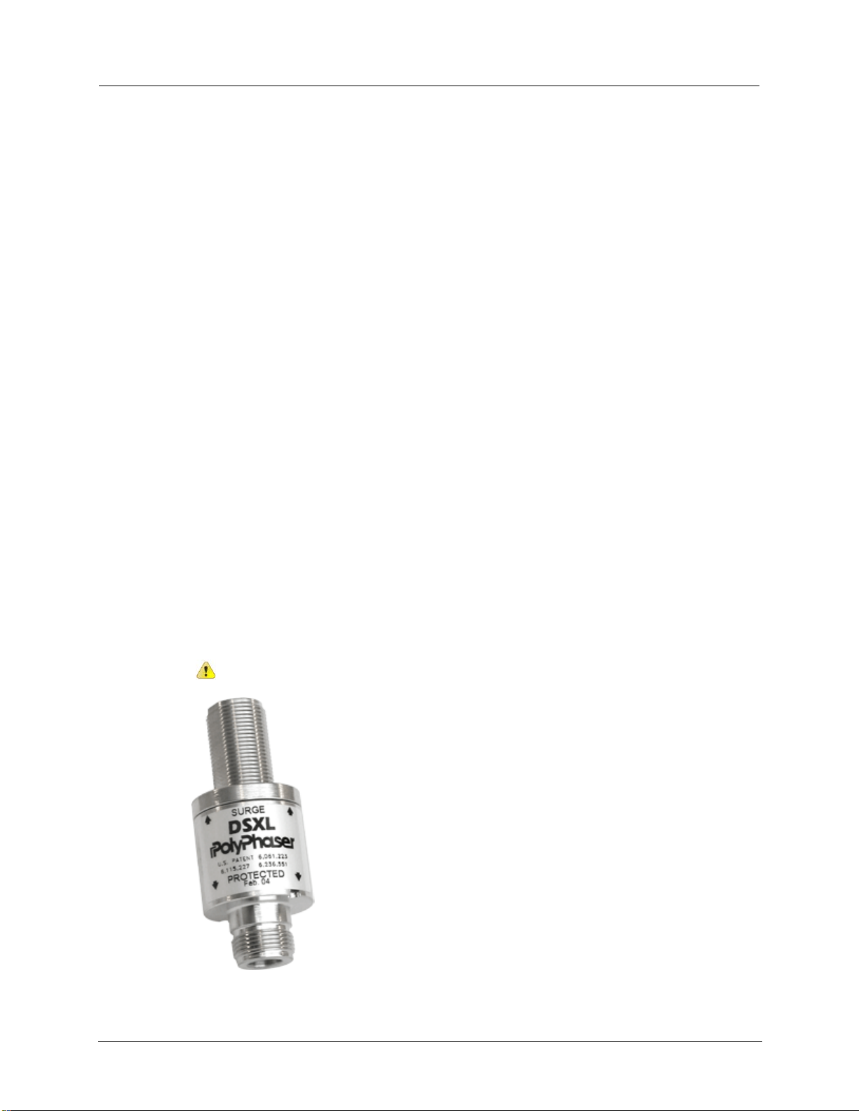
Lightning Arrestor
A lightning arrestor (or surge protect or) capable of wit hst anding multiple lightni ng strikes
should be installed when using a remote moun t antenna. This helps protec t the
CCU/Repeater in the event of a lightning strike.
The lightning arr es tor i s fit ted to the c oaxial a ntenna cable at the SUR G E end and t he RF
jumper cable that connects to the CCU/Repeater module at the PROTECTED end. It
inc ludes a bulkhead conne c tor interface that mou nts t o a gr ound pl ate with a was he r a nd
nut. The arrestor is also furnished with a ground lug, if your installation does not have
provisions for a ground plate. The ground lug on the arrestor is designed for #2AWG solid
or s tra nded wire. The gr ound wire must be crimped to thi s lug, neve r soldered.
Caution The lightning arrestor must be connected to an earth-ground.
CCU 100 and Repeater 100 Installation Guide 11
Page 18

Chapter 2 Planning a CCU/Repeater Installation
Proprietary and Confidential
The top and bottom ends of the coaxial cable attached to the tower should be electrically
grounded with kits for lightning protection. The antenna input connection cannot serve as
the t op ground poi nt. For c able lengths in excess of 200 feet, ground the vertical cable run at
the midpoint and then each additional 200 feet.
Note The i nstaller mus t supply any mount ing brackets and cabl e -management cl ips
to secure the coaxial cable to the tower or structure, when using a remote mount
antenna. Consult your cable manufacturer for specifications on proper clips and
groundi ng kit s. Conduit c l amps and tie wraps are not sati sfa c tory methods f or
securing coaxial cables.
For remote installation with a high gain antenna, a li ghtning arrestor is supplied by Itr on in
the CCU 100/Repeater 100 kit materials.
AC Mains Power
The AC mai ns wiring to t he CCU/Repeater utilizes a three c onductor cable. This c able can
be terminated with either a NEMA L5 -15 (125V, 15A) or a NEMA L6-15 (250V, 15A)
loc king plug i n order t o meet local el e c tri c al c odes. T he CCU s hould be power e d by a
dedicat ed 10A circuit. The C C U/R ep eater should not be connected to a circuit protect ed by
a GFCI breaker. Power wiring on the Itron supplied power cable follows conventional color
coding for AC wiring: Green/Ground, White/Neutral, Black/Hot.
DC Mains Power
The DC wiring to the CCU/Repeater util i zes a two c onductor cable. The CCU sho ul d be
connect ed to a 10A DC circuit breaker or fuse. Wiring of the Itron supplied two conductor
cable is accompl ished by a ttachi ng the red wire t o a +12V source and a ttaching the blac k
wire to ground.
12 CCU 100 and Repeater 100 Installation Guide
Page 19

Mat eri als No t Provided by Itron
Proprietary and Confidential
Materials Not Provided by Itron
The fol lowi ng mater ials are not provided by Itron in the CCU/Repeater kit, but are required
for installation.
Please a cquire thes e items prior to beginn ing an ins tall ation.
• Coaxial cable on page 13
• Connectors on page 14
• Mounting hardware on page 14
Coaxial Cable
When remote mounting the antennas, coaxial cable must be supplied to connect the ant enna
to the CCU/Repeater. The proper s ize of c able is depe ndent on t otal c able length and
fre quency. Coaxial c able also requires proper hoi sting grips, ground kits, connector s,
jumpers, hangers, and weather proofing material. Coaxial cable and accesso ri es are not
provided by Itron. Coaxial c able s yst e m s mus t be installed ac cor ding to the manufac turer' s
specifications. Itron recommends using qualified radio installation contractors to install the
remote a ntenna s yste m. See Motorol a R56 guidelines f or r ecommended practices on cable
installation.
Cable lengths should not exceed 12 feet, except when used with the high-gain ante nna.
Remote Mount Endpoint A nte nna on a Stan dard CCU/Repeat er
When select ing cabl e for the rem ote m ount unit y gain endpoint antenna on the stand ar d
(non-tower) C CU/R epeater , total cabl e loss c annot exceed 1.5 dB to maintain system
performanc e. Al low 0.1 dB loss for each c onnector.
Remote Mount High Gain (8.15 dBi) E ndpointed Antenna on a Tower C C U
When selecti ng cable for t he remote mount high gain ( 8.15 dBi) endpoint antenna on the
tower CCU, total calculated loss between the tower cabinet and the antenna must be greater
tha n 2 dB, but l es s than 3. 5 dB.
Warning This 2 dB loss is required to prevent exce eding the maximum EIRP,
as set by the FCC.
Allow 0.1 dB loss for each c onnector . If required, a 1 dB attenua tor ( similar to t he
Pasternack PE7002-1) may b e used to attain the de sired power at the ante nna.
CCU 100 and Repeater 100 Installation Guide 13
Page 20

Chapter 2 Planning a CCU/Repeater Installation
Proprietary and Confidential
Antenna Sweep Tes t
Tot al Coaxial length
only)
only)
After r e mote a ntenna installation perform an ant e nna syst e m sweep test and ver ify t hat
VSWR (voltage standing wave ratio) does not exceed 1.5:1. For more information, see
Perfor m an Antenna Sw eep T es t on page 55.
Caution All coaxial cable used to connect an antenna to the CCU/Repeat er must be
properly grounded at the top and bottom of the coaxial line. A dditionally, any cable
lengths of 200 feet or greater must be grounded each 100 feet. See Lightning
Arrestor on page 11 for more information.
The following table lists the possible coaxial cable lengths and specifications.
Coax specification 0-120 ft. 121-200 ft. ( high-
gain a nte nna
201-250 ft. ( highgain a nte nna
Standard black jacket cable AVA5-50 AVA6-50 AVA7-50
Optional fire retardant cable AVA5RK-50 AVA6RK-50 AVA7RK-50
Cable d ia meter ( nomi nal) 7/8 in. 1-1/4 in. 1-5/8 in.
Cable weight (lb./ft.) 0.33 0.46 0.70
Minimum bend radius 10 in. 8 in. 15 in.
Cable attenuation @ 915 MH z ~ 1.2 dB/100 ft. ~ 0.84 dB/100 ft. ~0.70 dB/100 ft .
Antenna Connectors
Connectors for the e ndpoint and WAN antenna ca bles need to be ma le Type N connectors
and must be sized according to the type of coaxial cabl e use d. The GPS cable requires T NC
male and SM A male c onnectors. These connecto rs ar e available f rom a variety o f
manufacturers.
Important All coaxial cable connections must be properly weather-proofed per
industry standar ds unl es s ot he rwise spec ifie d. If the CCU/Repeater is installed
indoors, only the connections located outside need to be weather-proofed.
14 CCU 100 and Repeater 100 Installation Guide
Page 21

Mat eri als No t Provided by Itron
Proprietary and Confidential
Profile
Mounting surface
Suggested hardware/sizing
Mounting Hardware
Depending on your installation location and configuration, the following mounting
hardware must be supplied by the installer to properly attach the CCU/Repeater to the
mounti ng surface.
Caution Since each installation is unique, you must ensure that the mounting
hardware you supply can securel y support the CCU/Repeater. The CCU/Repeater
(minus attachment hardware) weighs 7 pounds. It r on r ecommends consulting with a
qualified engineer to verify load requi r em ents and safety issues. Also, be sure to
check and comply with local co des when instal ling the CCU/Repeater.
Utility po le Wood or steel pole High-strength stainless steel straps
Light pole Steel lig ht po le High-strength stainless steel straps
Outdoor wall or pole with
remote ante nna
Concrete, wood, or steel wall 1/4 inch-20 lag screws or 1/4 inch-20 mo lly bolts
Wood or steel pole High-strength stainless steel straps
Indoor wall o r po le w ith
remote ante nna
Concrete, wood, sheetrock, or
steel w all
Wood or steel pole High-strength stainless steel straps
Pipe 2.5 inch to 3.5 inc h galv anized
steel p ipe
1/4 inch-20 lag screws or 1/4 inch-20 molly bo lts
Two pipe mount b rackets f or pipes up to 3 .5 i nches in
diameter, suppl ied b y Itron (p art numbe r FAB -0192001, two brackets are required for each
CCU/Repeater).
CCU 100 and Repeater 100 Installation Guide 15
Page 22

Chapter 2 Planning a CCU/Repeater Installation
16 CCU 100 and Repeater 100 Installation Guide
Proprietary and Confidential
Page 23

Proprietary and Confidential
C
HAPTER
3
Installing the CCU/Repeater
This chapter shows you how to install a CCU/Repeater in the field, using the Itronrecom mended ins t alla t i on met hod .
The CCU/Repeater can be installed in a variety of wa ys. Severa l d iffere n t C CU/ Repea ter
installation profiles ar e s hown in thi s cha pter, for both mains powered and s olar powered
CCU/Repeaters.
Warning Before installing a CCU/Repeat er , ensure that the selected location can
support the weight of t he CCU/Repeater and mounting hardware. A thorough
structural analysis should be perform ed by a qualified engineer at your desired
location prior to installation. Itron is not responsible for im pr oper installations or for
install ations at a site that cannot adequately support the CCU/Repeater.
Installation Overview
The following section shows you how to install a CCU/Repeater using the Itronrec ommended profile. This profile calls for the C CU/Repea ter to be mounted to a 2 inch
dia meter vertical pip e. A 110V source supplies mains power to the CCU/Repeater.
Caution Prior to installing a CCU in the field, be sure to configure it as described in
the Collector Conf igur ation Application v4. 0 Use r Guide. A CCU cannot be
configured after it has been installed in the field. Repeaters do not require pr einstall ation configuration.
There ar e sever al mai n steps to perform. Ea ch step is des cr i be d in mor e detail in t he
following sections.
1. Attach t he re mote a ntennas on page 18 (if necessa ry).
2. Attach t he direct m ount endpoint antenna on page 19 (if necessary).
3. Attach the CCU/Repeater to the mounting surface on page 21.
4. Connect the cables on page 29.
5. Install the battery on page 30.
Cauti on D o not move or transport the CCU without first disconnecting the battery.
Moving or tilting a CCU with the battery connected may cause the CCU to reset to the
fac tory image .
6. Provide power on page 32.
7. Perfor m an antenna sweep test on page 55.
CCU 100 and Repeater 100 Installation Guide 17
Page 24

Chapter 3 Installing the CCU/Repeater
Proprietary and Confidential
Att a ching the GP S/WAN Remote Antennas
The GPS and WAN remote antennas can be attached to pipes, poles, walls, and davit arms.
A typical pole mount assembly is shown below.
To attach the GPS/WAN remote antennas
• For s tep-by-step assembly instructions, see the GPS/WAN Remote Antenna Mounting
Kit Assembly Guide included wi th the GPS/WAN Remote Antenna Mou nting K i t.
18 CCU 100 and Repeater 100 Installation Guide
Page 25

Attaching the Direct Mount Endpoint Antenna
Proprietary and Confidential
Attaching the Direct Mount Endpoint Antenna
Attach t he direct m ount endpoint antenna bef ore mounting the CCU/Repeat er in its
per mane nt loc a t i on.
To attach the direct mount endpoint antenna
1. Screw the antenna ont o the t op of the CCU/Rep eater. Be car eful no t to c ross -thread
the connectors. Do not over tighten.
2. Slide the antenna sleeve over the antenna, ensuring that the front of the antenna sleeve
(1) is to the front of the CCU/Repeater .
CCU 100 and Repeater 100 Installation Guide 19
Page 26

Chapter 3 Installing the CCU/Repeater
Proprietary and Confidential
3. Usi ng the included screws, washer s, and lock washers, screw the antenna sleeve to the
top of the CCU/Repeater. Tighten t he screws to 5 t o 6 in/lbs.
20 CCU 100 and Repeater 100 Installation Guide
Page 27

Attaching the CCU/Repeate r
Proprietary and Confidential
Attaching the CCU/Repeater
The CCU/Repeater ma y be a ttac hed to a va riety of surf aces. Se e the f ollowing sect ions for
diagrams showing some of the possible configurations.
• Pipe mount on page 22
• Pole mount on page 24
• Wall mou nt on page 26
• Davit arm moun t on page 27
Mounting Hardware
This set of hardware ca n be a dapt ed to m ount the CCU/ Repeat er in ma ny di f ferent
locations.
For pole or pipe mounts , the m ounting har dware consists of a mounting pla te, two brac ke ts,
four bolt s, and a set sc rew.
For a wall m ount , us e two metal brackets (not shown below), four mounti ng bol ts, nut s, and
loc k was he rs to prepa re the C CU for mounti ng. I tron does not s upply the har dware
nec essa ry to m ount the CCU wall mounting bracket s to the wall.
An integrated mount ing s upport on the back of the C CU/Rep eater enclosure slide s int o the
slot in the center of the mounting bracket. A set screw locks the CCU/Repeater to the
mounti ng br acket . Orientati on of the enclosure ma y be a djust e d +/- 16 degrees horizontal
to com pensate for different angles.
CCU 100 and Repeater 100 Installation Guide 21
Page 28

Chapter 3 Installing the CCU/Repeater
Proprietary and Confidential
Pipe Mount
The i mage below illustrates a typical vertical pipe installation. The CCU/Repeater may also
be attached t o a horizontal pipe.
In this case the CCU/Repeater mounting plate is attached to the vertical pipe with the
mounti ng br acket s and the CCU/ Repeat er enc losure is sec ure d to the mounting plate. The
power cable is connected to the available AC service with either the un-terminated pigtail
power cable or the grounded outlet plug power cable (optional).
To mount the CCU/Repeater on a pipe
1. Usi ng the two m ount ing bra c kets and four bolts , at t ach t he mou nting plate to the pi pe.
22 CCU 100 and Repeater 100 Installation Guide
Page 29

Attaching the CCU/Repeate r
Proprietary and Confidential
2. Insert the mounting disc into the mounting plate keyhole.
3. Using the provided set screws, secure the CCU to the mounting plate in the upright
position.
CCU 100 and Repeater 100 Installation Guide 23
Page 30

Chapter 3 Installing the CCU/Repeater
Proprietary and Confidential
Pole Mount
If the vertical pipe or pole exceeds 6.75 inches in diameter, metal bands may be used in
place of the mounting brackets to secure the mounting plate to the pipe or pole. Two sets of
slots (1.5 in. long) on the mounting plate are provided for the metal bands. If the pole is
large in diameter, I tron recommends that the e ndpoint ante nna be remote mounted to
achieve optimum RF per for manc e.
To mount the CCU/Repeater on a pole
1. Insert the mounting disc (on the back of the CCU) into the mounting plate keyhole.
24 CCU 100 and Repeater 100 Installation Guide
Page 31

Attaching the CCU/Repeate r
Proprietary and Confidential
2. Using the provided set screws, secure the CCU to the mounting plate in the upright
position.
3. Usi ng tw o stee l straps, at tac h the mount i ng plate to the pole.
CCU 100 and Repeater 100 Installation Guide 25
Page 32

Chapter 3 Installing the CCU/Repeater
Proprietary and Confidential
Wall Mount
The following image illustrates a wall mount installation. In this scenario two br ackets are
secured to the flat wall surface and the CCU/Repeater is bolted to the brackets. The power
cable ma y be connec ted to a standar d outl et or other availa ble AC ser vice. It may be
necessary to use the remote antenna kit to achieve optimum RF pe rformance and GP S
coverage if m ounted indoors or if t he wall obstructs the de sired RF path.
To mount the CCU/Repeater on a wall
1. Using four bolts, secure the CCU to the two wall mounting brackets.
2. Usi ng four a ppropriate s c rews or bolts (not prov ided by I tron), attach t he mounting
brackets to the wall.
26 CCU 100 and Repeater 100 Installation Guide
Page 33

Attaching the CCU/Repeate r
Proprietary and Confidential
Davit Arm Mount
The figure below illustrates a typical utility pole or street light pole installation. The
CCU/Repeater i s mou nted on a davit arm or the street light ar m. Two types of pow er
connections are typical. A photocell adapter cable may be used when the CCU/Repeater is
mounted on a street ligh t arm. T hi s cable plugs into the phot ocel l sens or of the stre et li ght.
If the CCU/Repeater i s mou nted on a da vit arm with no street light, the un-terminated
pigtail power cable may be connected to the AC service at the pole.
To mount the CCU/Repeater on a davit arm
1. Usi ng the two m ount ing bra c kets and four bolts , at t ach t he mou nting plate to the davit
arm.
CCU 100 and Repeater 100 Installation Guide 27
Page 34

Chapter 3 Installing the CCU/Repeater
Proprietary and Confidential
2. Insert the mounting disc into the mounting plate keyhole. The following photos are
shown off the davit arm for clarity.
3. Using the provided set screws, secure the CCU to the mounting plate in the upright
position.
28 CCU 100 and Repeater 100 Installation Guide
Page 35

Connecting Cables
Proprietary and Confidential
Connecting Cables
Connect the remote antenna cables (if needed), Ethernet cable (if needed), and grounding
wire.
Because of the variable requirements for cable length, cables are not provided by Itron.
Important All coaxial cable connections must be properly weather-proofed per
industry standards unless otherwise specified. If the CCU/Repeater is installed
indoors, only the connections located outside need to be weather-proofed.
To connect cables
1. The GPS c able has a n SMA connec tor on one end and a TNC c onnec tor on the other
end. Connect the SMA connector end of the GPS antenna cable to the CCU/Repeater.
Connect the TNC end of the GPS cable to the remote GPS antenna.
2. The WAN cable has a TNC connector on one end and an N connector on the other
end. Connect the N connector end of the WAN antenna cable to the CCU. Connect the
TNC end of the cable t o the remote WAN antenna.
Note Repeat ers do not use WAN antennas.
CCU 100 and Repeater 100 Installation Guide 29
Page 36

Chapter 3 Installing the CCU/Repeater
Proprietary and Confidential
3. If you are usi ng a remot e e ndpoint ant enna , at tach the endp oint ant e nna cable to the
connector on the top of the CCU/Repeater.
Import an t Using weatherproof tape, wrap the remote endpoint antenna connection
on the top of the CC U /Repeater. Wrap from the CCU /Repeater up to the antenna
cable.
4. If you are using an Ethernet backhaul, attach the Ethernet cable ensuring the weather-
tight connector is properly secured. If the Ethernet connection is not used, secure the
weatherproof cap.
5. The grounding lu g should be attac hed to earth ground according t o local c odes.
Installing the Battery
To install the batte ry
1. Remove the battery cover by loosening the four screws securing it.
These are captive screws and do not need to be fully removed from the battery cover.
30 CCU 100 and Repeater 100 Installation Guide
Page 37

Installing the Battery
Proprietary and Confidential
2. Plug in the four pin bat tery wiring har nes s. The harnes s s houl d snap i nto pl ac e,
providing a secure connection.
3. Slide the battery into the battery compartment.
4. Replace the battery compartment cover, and torque the screws to 6 inch-pounds.
CCU 100 and Repeater 100 Installation Guide 31
Page 38

Chapter 3 Installing the CCU/Repeater
Proprietary and Confidential
Providing Power
The final step of the CCU/Repeater installation is to provide power to the CCU. Depending
on the CCU /Repeater model , ei ther a two pin cable ( DC), three pin cable (AC ), o r a five pin
cable (solar) is required.
Caution Do not move or tilt the CCU for one minute after connect ing power.
Moving or tilting a CCU too soon af ter connecting power may cause it to reset to
the factory image.
To provide power
1. Plug the appropriate cable in to the CCU/Repeater.
Note The connector is keyed so that the cable can connect in only one orientation.
2. Sec urely f aste n the power cable to the CCU/Repeater by tightening the retaining nut
on the cable.
32 CCU 100 and Repeater 100 Installation Guide
Page 39

AC Mains Non-Remote Installation Diagram
Proprietary and Confidential
AC Mains Non-Remote Installation Diagram
Tower Installation
Warning Before installing a Tower CCU, ensure that the selected location can
support the weight of t he Tower CCU and m ounting hardware. A thorough
structural analysis should be perform ed by a qualified engineer at your desired
location prior to installation. Itron is not responsible for im pr oper installations or
for install ations at a site that cannot adequately support the Tower CCU.
All coaxial cable connections must be properly weather-proofed per i ndustry standards
unl ess otherwise specified. T hi s includes a ny connections for the antennas and the Tower
CCU. If the Tower CCU is installed indoors, only the connect ions loca ted outs ide need t o
be weat he r -proofed.
Important T o prevent exceeding the maximum EIRP set by the FCC, there must
be at least 2 dB of loss between the antenna connector at the base of the tower
cabinet and the high gain e ndpoint antenna . Do not exceed 3.5 dB of loss t o
mai ntain sys tem perf orma nce. Onl y use the I tr on approved high gain antenna.
Because of the size and weight of the Tower CCU, Itron recommends that more than one
person be present for the installation. See Ante nna Specificati ons on page 49 for more
information.
CCU 100 and Repeater 100 Installation Guide 33
Page 40

Chapter 3 Installing the CCU/Repeater
Proprietary and Confidential
Tower Installation Overview
The Tower CCU 100 (TCU) installation differs significantly from other CCU 100
installation profiles in that the CCU 100 is installed within a cabinet enclosure at the base of
a ra dio tower and all of t he antennas are mounted r e m otely. The st anda rd cabi ne t protec ts
the hardware from adverse environmental conditions and provides easy access for servicing
the C CU and its related compone nts.
The TCU box comes preassembled except for the CCU. The CCU must have the ICS
procedure performe d prior to installing the C CU in t he TCU box.
34 CCU 100 and Repeater 100 Installation Guide
Page 41

Tower Installation
Proprietary and Confidential
TCU Components
RF Filter
1
Battery
2
Surge protection devices (SPDs), receptacle, terminal blocks
3
CCU mounting plate
4
Roxtec™ block
5
Wiring diagram
6
Document holder
7
Air filters There are two air filters, one shown at (8) and another behind the fan (9).
8
Fan
9
CCU 100 and Repeater 100 Installation Guide 35
Page 42

Chapter 3 Installing the CCU/Repeater
Proprietary and Confidential
To assemble the Tower CCU 100
1. Attach C CU to C CU mounting pl ate.
a. Insert the CCU mount ing disc into the mounting plate keyhole.
b. Slide the CCU down until you feel it click into place.
2. Connect cable from CCU to RF filter.
3. Connect grou nd wire to CCU.
4. (optional) Connect the Ethernet cable to the CCU and the top of the 10/100 BT SPD.
Feed the external Ethernet cable through the Roxtec block and connect it to the
bottom of the 10/100 BT SPD.
Instructions for using a Roxtec Block are supplied in the TCU cabinet.
36 CCU 100 and Repeater 100 Installation Guide
Page 43

Tower Installation
Proprietary and Confidential
5. Connect the battery to the connector on the battery door of the CCU.
The battery door connection is only present on CCUs designed for TCU installations.
6. Feed the GPS and WAN (if r e quired) ante nna c ables through t he Roxtec block and
connect them to the CCU.
7. Connect the power cable to the CCU.
8. See Atta c hing t he Remot e Ante nnas on page 18 for instructions on installing the
antennas.
9. Connect power to the cabinet. See the wiring diagram on the inside of the cabinet
door.
CCU 100 and Repeater 100 Installation Guide 37
Page 44

Chapter 3 Installing the CCU/Repeater
Proprietary and Confidential
AC Tower Installation Diagram
38 CCU 100 and Repeater 100 Installation Guide
Page 45

Solar Powered Installation
Proprietary and Confidential
Solar Powered Installation
All coaxial cable connections must be properly weather-proofed per i ndustry standards
unl ess otherwise specified. T hi s includes a ny connections for the antennas and the
CCU/Repea ter. If the CCU/R epeater is i nstalle d indoors, only t he connection s loc at ed
outside mus t be weather-proofed.
Warning Before installing a CCU/Repeat er , ensure that the selected location
can support the weight of the CCU/Repeater, mounti ng hardware, solar panels,
and batteries. A thor ough str uctural analysi s should be performed by a qualifi ed
engineer at your desi r ed loca tion prior to install ation. Itron is not responsible for
improper install ations or for installations at a site that cannot adequatel y support
the CCU/Repeater.
Because of the size and weight of the solar system, Itron recommends that mor e tha n one
person be present for the installation.
Solar Installation Overview
The Solar CCU/Repeater installation differs slightly from other CCU 100 installation
profiles in that the power comes from a separate cabinet enclosure which houses the solar
controller and batteries.
The Sola r CCU/ Repea ter is mounted l ike other C CU/Repea ters , but the power com es f rom
the s olar cabinet which houses the solar con troller and batter i es . T he p ictur e below shows a
solar tower installation.
CCU 100 and Repeater 100 Installation Guide 39
Page 46

Chapter 3 Installing the CCU/Repeater
Proprietary and Confidential
Solar Wiring Diagram
The diagram below illustrates how a solar panel system must be wired to connect to the
CCU/Repea ter. Thi s encl o sure is pre-wired. You a re required to connect onl y the power and
the ground.
To assemble the Solar CCU 100
1. Mount the sol ar panels and bat tery bo x as desc ribed in the Installation, Operation,
and Maintenance Manual suppli e d wit h the solar system.
2. Wire the five conductor power cable to the solar cabinet, as show n in the Sola r Wir ing
Diagram on page 40. Use the watertight grommet supplied with the solar cabinet.
3. Mount the CCU/Repeater i n the desired loca tion.
Note The power cable from the solar battery box to the CCU/Repeater should be less
than 12 feet long.
4. Connect grou nd wire to CCU.
5. If required, connec t t he a ntenna and E thernet cables to the CC U /Repeater.
6. Connect the battery to the CCU.
7. Connect the power cable to the CCU.
8. See Attac hing t he Remot e Ante nnas on page 18 for instructions on installing the
antennas.
40 CCU 100 and Repeater 100 Installation Guide
Page 47

Solar Powered Installation
Proprietary and Confidential
Solar Installation Diagram
The diagra m below shows a typical solar pow ered inst allati on.
CCU 100 and Repeater 100 Installation Guide 41
Page 48

Chapter 3 Installing the CCU/Repeater
42 CCU 100 and Repeater 100 Installation Guide
Proprietary and Confidential
Page 49

Proprietary and Confidential
C
HAPTER
4
Battery Care and Replacement
In thi s chapter, you will learn how to perform field mai ntenance on the CCU/R epeater
battery. With some routine care, the batteries used by CCUs/Repeaters will perform at
optimal levels for several years.
The following sections show you how to store and charge spare CCU/Repeater batteries, as
well as how to replace a CCU/Repeater battery in the field.
Shipping Requirements
Warning! Electrical fire hazard—protect against shorting.
Terminals can short cir cu it and cause a fire if not insulated dur ing shipping.
Requirements for shipping batteri es:
• Batteries must be labeled "NONSPILLABLE" duri ng shippi ng. Follow
all federal shipping regulations. S ee CFR 49 Parts 171 thr ough 180,
available online at
• Batteries must hav e short ci r cui t protection during shipping. Exposed
terminals, connectors, or lead wires must be insul ated with a durable
inert material t o pr ev ent exposure during shipping.
Failure to comply with these requirements can cause a fire during shipping and
handling.
www.gpoaccess.gov
CCU 100 and Repeater 100 Installation Guide 43
Page 50

Chapter 4 Battery C are a nd Replacemen t
Proprietary and Confidential
Battery Storage and Charging
To ensure maximum lif e span and effi cie ncy from yo ur CCU/Repeater bat ter ies , Itron
recommends the following storage and maintenance procedures.
Long-Term Storage
Bat teries ma y be store d for up t o two yea rs at room temper ature (25°C or 77°F) , and then
may be recharged wit h no los s in cell r eliabilit y or perfor ma nce ca pabilities. T he exampl e
storage time versus temperature chart below is a plot of maximum storage time as a
functi on of storage temp erature. This curve s hows the maximum number of days at any
given temperature, from 10°C (50°F) to 65°C (149°F), for the battery to discharge from a
fully charged state of about 6.42 volts (2.14 volts per cell) down to a zero charge state of
5.79 volts or (1.93 volts per cell). The battery should not be allowed to discharge below
5.79 volts because of the danger of damaging the performanc e charac teristic s of the battery
permanently.
When bat teries a re st ored at or near 25°C (77°F ) it is r ec ommend t o conduct an open circuit
voltage (OCV) audit every six months and recharge when OCV readings approach 6 volts
(2.00 volts per cell). If storage temperatures are significantly higher than 25°C (77°F), even
for short durations , the fre quency of OCV a udits mus t increase.
It is important to recognize that the self-discharge rate of the battery is non-linear. The ra te
of s e lf-di scha rge changes as the st at e o f ch arge (SOC) o f the bat tery c h anges . The ti m e
taken for a battery to discharge from a 100% SOC to 90% SOC is different from the time it
ta kes to s e l f -discharge from a 20% SOC to a 10% SOC.
44 CCU 100 and Repeater 100 Installation Guide
Page 51

Battery Storage and Charging
Proprietary and Confidential
State of Charge
The state of char ge (SOC) of the battery c an b e approxi ma ted by us ing t he c urve shown i n
the chart below. This curve is accurate to within 20% of the true SOC of the cell under
considera tion, if it has not been c harged or di sc har ge d within the past 24 hours. The curve is
accura te to wi thi n 5% if the cell has not seen any act ivity, c har ge or discha rge, for the past
five da ys .
Charge the Battery
You can char ge spare CCU/Repeater batteries individually or in groups to save time.
When charging batteries, there are several items you need:
• Power Sonic PSC-124000A-C charger
• Molex 39-01-4046 connector
• CCU/Repea ter batteries
The recommended method for charging the batteries is to utilize the Power Sonic PSC124000A-C charger . The P ower Soni c charger needs to be modi fied so t hat it ca n be
plugged directly into the battery. This is done by retrofitting the output of the charger to a
Molex 39-01-4046 connector with the red wire going to pin one and the black wire going to
pin two of the connector. Follow the instructions that come with the charger for correct
operation.
After charging, the battery should be removed from the charger for at least 24 hours. After
this time the open circuit voltage should be measured to verify that it is at or above 6.4
volts.
Note Batteries in storage nee d to b e charge d routinely for ma ximu m shel f lif e. For
mor e i nformation , see L ong Term Storage on page 44.
CCU 100 and Repeater 100 Installation Guide 45
Page 52

Chapter 4 Battery C are a nd Replacemen t
Proprietary and Confidential
Battery Service Life
All batteries have extremely variable service life, depending upon the type of cycle,
environment, and charge to which the cell or battery is subjected during its life. There are
two bas ic typ es of s ervic e li fe: cycle li fe and calenda r li fe. The bat tery in the CC U/R epeater
is called in to ser vice only duri ng pow er outages, so in t his case only c ale ndar (or floa t) life
is applicable.
Calendar Life
The de sign c ale ndar (or float) li f e of the battery is up to eight to ten years at room
temperature (25°C/77°F) and under proper charging conditions.
This design life has be en con firmed by the use of acc e lerated testing methods that are
widely acc epted by both ma nufa c turers and users of sealed-lead batteries. High
temperatures are used to accelerate the aging process of the battery under test.
The f loat lif e of a cell is c ut i n half for roughly e ve ry 8°C ( 14.4°F) rise in ambient
temperature. The example below shows the relationship between ambie nt t e mperature a nd
float life for batteries that have a float life of ten years at 25°C (77°F).
A ten year battery lasts for five years at 33°C (91.4°F) and only 2½ years at 41°C (105.8°F).
Preventative Maintenance
Itron recom mends a preventative maintenance cycle of a two-year replacement in extreme
environments (average temperatures greater than 110°F/44°C), or five years in non-extreme
environments (average temperatures less then 90°F/31°C).
46 CCU 100 and Repeater 100 Installation Guide
Page 53

Replacing t he Integrated Battery
Proprietary and Confidential
Replacing the Integrated Battery
The following procedure shows you how to replace the integrated battery once it has been
installed in the field.
Warning Risk of explosion if battery i s replaced by an incorrect type. Always
replace with Itr on par t number B AT-0045-001.
For i nformat ion on batter y dispo sal or r ecycling , con tac t Ener Sys at 1.800.363.7797 or
recycling@enersys.com.
To replace the battery
1. Remove the battery compartment cover by loosening the four screws securing it.
2. Slide the battery out of the battery compartment.
3. Carefully, disconnect the four pin connector.
4. Connect the new battery's four pin connector.
5. Slide the new battery into the battery compartment.
6. Replace the battery compartment cover, and torque the screws to 6 inch-pounds.
CCU 100 and Repeater 100 Installation Guide 47
Page 54

Chapter 4 Battery Ca re an d Replacement
48 CCU 100 and Repeater 100 Installation Guide
Proprietary and Confidential
Page 55

Proprietary and Confidential
Component
Weight
A
PPENDIX
A
Detailed CCU/Repeater Specifications
CCU/Repeater Dimensions and Weight
Weight is shown in pounds and dimensi ons a re shown in inches.
CCU/Repeater 7 lbs
AC tower unit 76 lbs
Remote GPS/WAN antenna system 6 lbs
Remote 900 MHz antenna system 3.5 lbs
900 MHz a ntenna (sta ndard, unity gain) 1 lb
Pole mounting kit 3 lbs
Wall mo unting kit 2 lbs
CCU 100 and Repeater 100 Installation Guide 49
Page 56

Appendix A D etailed CCU/Repea ter S pecifi cations
Proprietary and Confidential
Antenna Specifications - 100
polarized
Specifi c ations f or the standard (unity gain) e ndpoint ant enna and high ga in antenna a re
shown in the following table.
Important All coaxial cable connections must be properly weather-proofed per
industry standar ds unl es s ot he rwise spec ifie d. T hi s includes any connection s for
the ant e nnas and the CCU/Rep eater components. I f the CCU/Repeater i s installed
indoors, only the connections located outside need to be weather-proofed.
This device has been designed t o op erate with the antennas list e d below that have a
max imum gain of 8. 15 dBi. Antennas not inclu ded in thi s list or having a gain greater than
8.15 dBi are strictl y prohibi ted f or use with thi s devic e. The requi re d antenna impedance is
50 ohms.
Specification Vertically polarized High ga in (8.1 5dB i) Horizontally
Part number MSE-0316-001 MSE-0373-001 MSE-0303-001
Gain 0 dBd (2 .15 dB i) 6.0 dBd (8. 15 dB i) 2 dBd (4.15dBi)
Horizontal beamwidth Omnidirectional Omnidirectional Omnidirectional
Vertical beamwidth -3dB minimum, =/- 40
degrees from
horizontal
Electrical downtilt avai lable 0 degrees 0 degrees 0 degrees
Power rating 10W 200W 10W
Impedance 50 o hms 50 ohms 50 ohms
Termination Type N male Type N female Type N male
Lightning protection Direct ground Direct ground Direct ground
Overall length
radome di ame te r
Mounting area length n/a ~8 in. n/a
Weight (without clamps) 1 lbs. 6 lbs. 1 lb.
Maximum w ind spee d 160 mph 125 mph 160 mph
Wind load @ rated wind speed n/a 57 lbs. n/a
13 in.
2.375 in. OD
17 degrees 45 degrees
65 in.
1.310 in. OD
13 in.
2.375 in. OD
For the latest antenna part numb ers , see t he CCU 100 Ordering Guide or cont act your Itron
representative.
To reduc e potential r adio int erf erence to other user s, the antenn a type and i ts gain shou ld b e
so chosen that t he e quivalent isotropi c ally radia ted power (e.i .r.p. ) is not m ore than t hat
permitte d f or successful communic ati on .
50 CCU 100 and Repeater 100 Installation Guide
Page 57

Environmental Specifications
Proprietary and Confidential
Specification
Value
Specification
Value
Specification
Value
Environmental Specifications
The fol lowi ng envir onmental s pecifications are as s oc iat ed with a CCU/Repeater.
Operating temperature Components
Storage te mp e ratu re -40° C to 85° C
Humidity 0 to 90% non-condensing
Transmitter
GPS /WAN a nten na sy ste m: -33° C to 60° C
CCU/Repeater: -33° C to 60° C
Note Batteries may be stored for up to two years at 25° C
without period ic rec ha rgi ng. W he n ba tte rie s a re stored at t his
temperature, an open circuit voltage audit should be conducted
every six months.
If the storage te mpe ratu re is s ign if ica ntly highe r t ha n 25° C , t he
frequency of the audits must be increased.
Detailed specifications for the CCU/Repeater transmitter are described in the following
table.
Maximum transmit power at antenna 27 dBm
Frequency 903.0 MHz to 9 26.8 MH z (U SA )
CCU/Repeater Power Operating Range
Voltage 90 VAC to 265 VAC
Frequency 47 Hz to 63 H z
Average power 10 Wat ts ( b atte ry trickle c harge )
Peak power 50 Watts
CCU 100 and Repeater 100 Installation Guide 51
Page 58

Appendix A D etailed CCU/Repea ter S pecifi cations
Proprietary and Confidential
Battery Pack
If
Then
Specification
Value
Pin #
Wire Color
Signal
The battery pack is contained in it s own compar tment . T he bat tery pack i s a three-cell,
sealed, lea d acid ba ttery pa c k (6V, 4.5 amp-hours) that is field replaceable and designed to
last five years under normal circumstances. To ensure minimal impact upon battery life, a
preventative maintenance schedu le of t wo year repla cement is requir ed in a n extreme
environment, such as a desert installation. Normal preventative maintenance is every five
years f or non-hot environment installations.
Warning Risk of explosion if batter y is replace d by an inco r r ect type. Always
replace with Itr on par t number B AT-0045-001.
The batteries can power the system for a duration of 90 minutes in the case of a power
outage.
AC power fails The CCU/Repeater battery pack maintains system functions for
approximately 90 minutes. A message indicating the AC failure
is sent to the Network Software.
AC power is restored A message is sent to the Network Software indicating that AC
power has been restored.
The battery pack specif ic ations are listed below.
Type Sealed-lead acid, rechargeable
Power 6V, 4.5 amp-hours
Life Five years at 33° C. Battery life decreases by 50% for each 8° C
rise in temperature above 25°C.
Charge time 10 hours at 25° C
The battery in t he C CU/ Repeat er uses thre e EnerSys Cyclon lead-acid cel ls connected in
series to provide a nominal voltage of 6 volts. The battery is terminated with a four position
Molex connector (Molex P/N #39-01-4041) with the following pinout:
1 Red +V BATT
2 Black Ground
3 White Thermistor
4 White Thermistor
For i nformat ion on batter y dispo sal/re cyc ling cont act Ener Sys at 1.800 .363 .7797 or
recycling@enersys.com.
52 CCU 100 and Repeater 100 Installation Guide
Page 59

Proprietary and Confidential
A
PPENDIX
B
Status and Diagnostics
Status Indicator
The LED Stat us Indicator is primarily i ntended to support insta l lation personnel for
immediate feedback. The following sequences define the Fixed Network solution's
operational chara c teristics:
1. Eac h status seque nce is rep eat ed at 20 second i nter vals. T he fol lowing st atus
indica tors ar e enabled a t power-up or upon a communication failure with endpoints or
bac khaul.
Initial power-on and CPU has ini tialized, but neith er endpoi nt or bac khaul
communication has started: Morse "P" (● ▬ ▬ ●)
2. Super Raptor radio is seeing bubble-up endpoints but has not connected to the
bac khaul: Mors e "N" (▬ ●)
3. Backhaul radio is communicating, but no communication from endpoints: Morse "B" (
▬ ● ● ●)
4. Connected to backhaul radio & receiving endpoint packets: Morse "BN" ( ▬ ● ● ● ▬
● )
After 15 minutes of successful communication with backhaul and endpoints following
a power-up (or communication failure), the sequence changes to LED on for 10 mSec,
at 60 second intervals. This will continue until the next power-up.
Se quenc e details: The dot time: 100 mSec
The dash time is 300 mSec
Off T i m e betw een B and N: 700 mSec
Off time betwe en dot and dash: 100 mSec
CCU 100 and Repeater 100 Installation Guide 53
Page 60

Appendix B Status and Diagnostics
Proprietary and Confidential
Diagnostic Port
The wireless diagnostic port is based on the IEEE 802.11 LAN/MAN wireless specification.
The 802.11 Wi-Fi interface has been exclusively designed to support system diagnostic
capabilities and is intended to be available for field personnel use.
• The diagnost ic ra dio is avail able only at power up of the system or by t he reception of
a wake-up message that is received by the 900 MHz radio. Once the wake-up message
is validated by the 900 MHz radio the CCU 100 host powers on the diagnostic radio
interface and configures it for communications. By default, the operation period of the
diagnostic port is set to 30 minutes. Once this operational time has expired the radio
interface is disabled and eventually powers down until the next system power up event
or a wake-up command is sent to the 900 MHz radio.
• The diagnostic radio provides a dynamic W eb -based hosted inter f ac e f or
envi ronmental sens ors and syst e m health. The loc al diagnostic Web p ort f or the CCU
100 provides:
• Network oper ati ons i nformat ion
• Contents of r epor t list
• Number of endpoints on the list
• IDs of endpoi nts on t he list
• Conte nts of manage me nt list
• Number of endpoints on the list
• IDs of endpoi nts on t he list
• Conte nts of the igno re L ist
• Number of endpoints on the list
• IDs of endpoi nts on t he list
• Content of total endpoints received list
• Number of endpoints on the list
• ID’s of endpoints on the list
• Endp oint read reli abilit y statistics t able
• Hist ory of FNAS c ommands rece ived
• Source of time (GPS or NTP)
• List of pending 2-way com mands
54 CCU 100 and Repeater 100 Installation Guide
Page 61

Performi ng an Antenn a Sweep Test
Proprietary and Confidential
• CCU/Repea ter s t atus
• Power source (AC or battery)
• Battery state
• Intern al te mpera ture
• GPS status (number of satellites + GPS time and lat/lon position)
• Firmware versions
• Hardware versions
• Event log s
• Power outage logs
• WiFi access logs
• High temp/Low temp alarms
• Configuration collection
• TX power
• Endp oint filteri ng s et tings
• Confi guration it ems s et tings
• Firmwar e update in terface
• Force reboot
Performing an Antenna Sweep Test
If the endpoint antenna i s re motely mounted f or your installation, an ante nna sweep test
must be performed to verify that the antenna functions within acceptable tolerances at your
installation site.
This test should be performed under the following conditions:
• Beginning Freq uency: 902
• Ending Fr equency: 928
• VSWR E xpect ed Res ults: Must be 1.5 or less for the spe cified f re quency band.
• Retu rn Loss: Must be –18dB or bet ter f or the specif ied f requency band. Any
deviations from this return loss warrant further investigation.
• Test Point : Feed line connected to the antenna at the top; test from the lightning (or
surge) arrestor to the antenn a port.
• Results: Test results must be saved in. PDF format.
• Test Gear: Current and proper calibration; be sure that calibration is turned on during
the test. A qualified operator of the test equipment must perform the test.
Note If the system does not perform to the above test specifications, the reasons for
system failure and possible remedies must be identified before l eaving the
installation site.
CCU 100 and Repeater 100 Installation Guide 55
Page 62

Appendix B Status and Diagnostics
56 CCU 100 and Repeater 100 Installation Guide
Proprietary and Confidential
Page 63

Proprietary and Confidential
Index
A
AC service requirements • 9
antenna placement • 9
antenna specifications • 50
ant e nnas • 3, 5, 9, 10, 11, 18, 19, 50, 55
attaching the CCU/Repeater • 21
at tachi ng the direct m ount ant enna • 19
at tachi ng the remote ant e nnas • 18
B
battery • 44
battery pack • 52
battery st ora ge • 44
bracket s • 15, 21
C
cale nd ar life • 46
CCU c onfiguration • 1
CCU power operating range • 51
CCU spe cificati on s • 49
charging • 44
coaxial cable • 13
components • 2
connecting cables • 29
connectors • 14
D
davi t arm mount • 27
diagnostic port • 54
dime nsi ons • 49
E
endpoint antenna • 5, 9, 10, 11, 18, 19, 50, 55
environmental specifications • 51
Ethernet connections • 9
external Ethernet connections • 9
I
installation profiles • 7
installing the battery • 30
installing the CCU/Repeater • 17
L
lightning arrestor • 11
long-term storage • 44
M
mains powered installation • 12
maintenance • 43
mat erial s not provide d by Itron • 13
module • 2
mounti ng hardwa re • 15, 21
O
operat i ng range • 51
P
performing an antenna sw eep test • 55
pip e mount • 22
planning • 7
pol e mount • 24
power operating range • 51
preventative maintenance • 46
profiles • 7, 12, 39
propagation study • 8
providing power • 32
R
remote antenna placement • 9
remote a ntennas • 3, 5, 9, 10, 11, 18, 50, 55
Repeat er power operating r ange • 51
Repeat er spec ificat i ons • 49
replacing the battery • 47
G
GPS antenna • 3, 8, 10, 11, 18, 50, 55
PS cover age • 8
G
groundi ng • 1, 5, 10, 11, 13, 50
CCU 100 and Repeater 100 Installation Guide 57
S
servi ce life • 46
shipping requirements • 43
site selecti on • 8
s
iting • 8
Page 64

Index
Proprietary and Confidential
sola r installa tion diagram • 41
sola r pow ered inst all ation • 39
sola r wir ing diagram • 40
specifications • 49, 50, 51
st ate of c h arge • 45
status indicator • 53
storage • 44
T
transmitter • 51
W
wall mount • 26
WAN antenna • 3, 8, 10, 11, 18, 50, 55
WAN coverage • 8
58 CCU 100 and Repeater 100 Installation Guide
 Loading...