

Page 1

C&I Electric
Unit Test Procedure
Revision A
August 22, 2000
Page 2

Table of Contents
1. Equipment Requirements
2. PCA Sub-Assembly Power Supply Function Test
3. PCA Sub-Assembly RF Communications Test
4. Final Assembly Test
5. Shipping Preparation
Document Type: Test Procedure
Equipment Name: Innovatec C and I Electric
Author: Dithien V. Ho, RF Design Engineer.
Page 2 of 24
Page 3

1. Equipment Requirements
DVM (Digital vo ltmeter) w ith ohm and a m p fu nctio ns.
(Bel MERIT, DX451)
Dual Channel Oscilloscope, 100 MHz, 1GBs
(Tektronix, TDS 220)
Variable/Isolation AC Transformer (VIT), 0-150 Vac, 4 Amp
(Global Specialties, 1504)
PC with Windows 95 Operating System
NCTT, Test software, Version 2.2.0 or later
Field Service Unit with Version 2 Com m unications Ch ip (Silicon ians ) NCI installed
Unit Under Test (UUT), in this case the C&I Electric Unit, Fab. Rev. 5.3 or higher, Firmware Ver. 23 or
higher (CnI_V23.HEX, CS = 1c59)
(Innovatec, Relay, Rev. 5.3 or later)
Note: The information in parenth eses is a suggested test equipment Manufacturer and Model.
Equivalents may be substituted.
Document Type: Test Procedure
Equipment Name: Innovatec C and I Electric
Author: Dithien V. Ho, RF Design Engineer.
Page 3 of 24
Page 4

2. PCA S ub-Assem bly Power Supply and Battery Charg er Function Test
The f ollowing test in this section is t o be perfor med before the P CA is in stalled into t he Relay Hous ing.
2.1. Visual Inspection
2.1.1 Verify th at t he followin g components are installed w ith pr o per orientat io n / polarity, per as sembly
drawings: IC’s, Transistors, Diodes, Capacitors and Transformer.
2.1.2 Check for solder bridges/solder splash across traces or other conductors.
Pass____Fail___
2.2. Continuity Tests
2.2.1 Perform continuity test using DVM between metal tabs of U1, D2 and their heatsinks.
It should be open circuit or > 10 Meg Ohms for U1 and > 2 Meg Ohms for D2.
Pass____Fail___
2.2.2 Perf o rm con tin uity tes t b etween inp ut AC line con nectors (J3 to J 4 ) an d line to groun d (J3-H to
J1-G and J4-N to J1-G). Should be open circuit or >2 Meg Ohms.
Pass____Fail___
Document Type: Test Procedure
Equipment Name: Innovatec C and I Electric
Author: Dithien V. Ho, RF Design Engineer.
Page 4 of 24
Page 5

2.3. Power Supply Test
2.3.1. Connect 220 V variac (with isolation transformer and built-in fuse) to the input connector of
power supply. Then, slowly bring u p the voltage fr om 0 –85V wh ile monitoring the line current.
The line current at 85V should be < 15 mA
2.3.2. Wait few seconds and then verify all LEDs are turned on.
2.3.3. Measure the DC voltage between pins 3 and 21 of NCI connector (J7).
Specification: 5.5 – 5.7V DC.
2.3.4. Measure DC voltage between pins 15 and 21 of N CI connector (J7).
Specification: 5.0 to 5.1 Vdc
2.3.5. Measure DC voltage between pins 17 and 21 of N CI connector (J7).
Specification: 3.5 to 3.7 Vdc
2.3.6. Measure DC voltage between pins 2 and 5 of Molex connector (JP2).
Specification: 12 to 14 Vdc
Pass____Fail___
Pass____Fail___
Pass____Fail___
Pass____Fail___
Pass____Fail___
Pass____Fail___
2.3.7. Disconnect AC Power to UUT and install NCI unit onto the main board. Then, bring the voltage
slowly up to 85 Vac and repeat the above steps 4.2- 4.6.
Pass____Fail___
2.3.8. Bring u p the AC line voltage slowly from 85 to 265 Vac and rep eat the above steps with NCI
insta lled (f ull- lo ad).
Pass____Fail___
Document Type: Test Procedure
Equipment Name: Innovatec C and I Electric
Author: Dithien V. Ho, RF Design Engineer.
Page 5 of 24
Page 6

2.4. Battery Charger Tests
2.4.1. Connect battery charger module to C&I main board connector (JP2) and ver ify that the voltag e
across BAT + and BAT- on the charger board is set to 6.9 Vdc with 680 Ohm resistor c on n ected
across battery leads. Otherwise, adjust R7 P o t to set battery vo ltage to 6.9Vd c.
2.4.2 . Connect b attery leads to the b att er y termin als an d verify that v oltage across battery ter minals
has reached to 6.9Vdc (fully charged).
2.4.3. Disconnect AC power to C&I main board and verify th at the LEDs stays on (good indication that
UUT is powered by battery only).
2.4.4. Remove battery charger module from C&I board with battery leads disconnected from battery
terminals . Then con nect a d c pow er supply t o batter y lead s and slowly increase th e vo ltage fro m
0-6.5 Vdc while monitoring battery status pin (JP1-4). Verify that battery status pin goes high at
5.25 Vdc
2.4.5. Then, lower the dc Power supplies voltage slowly and verify that battery status pin (JP1-4) goes
low at 5.0Vdc.
Pass__Fail___
Pass__Fail___
Pass__Fail___
Pass__Fail___
Pass__Fail___
Document Type: Test Procedure
Equipment Name: Innovatec C and I Electric
Author: Dithien V. Ho, RF Design Engineer.
Page 6 of 24
Page 7

3. PCA S ub-Assem bly RF Communi cations Test
3.1. System Hardware Set-up:
3.1.1. Firmware Installation:
Remo ve AC line v o ltage fro m PCA p ower leads.
Disconnect battery lead from Charger Assembly.
Verify in s tallation of the EP ROM with appropriate firmw are rev er s ion.
3.1.2. NCI Ins t a l la t i o n :
In stall the NC I with version 2 c o m m unic ation s IC (Silicon ians) onto t he PCA with appropriate
antenna, 900 MHz, and 50 Ohms impedance.
3.1.3. Electric Meter RS-232 Communicat ion c on n ection:
In stall the Electric Meter to connecto r J7 as follow :
J7, Pin 12 = Tr an s m it (Pin 2 of the DB9 M eter commun ications cable)
J7, Pin 11 = Receive (Pin 3 of the DB9 M eter co m m unications cable)
J7, Pin 10 = Ground (Pin 5 of the DB9 Meter communications cable)
Power up t he electric meter.
3.1.4. Power on test:
Apply 120V AC line voltage to the PCA power leads, observe for the Status Indicator LEDs, make
sure the Green and Yellow LEDs are illuminated.
Reconnect battery lead to Charger Assembly.
Pass__Fail___
Document Type: Test Procedure
Equipment Name: Innovatec C and I Electric
Author: Dithien V. Ho, RF Design Engineer.
Page 7 of 24
Page 8
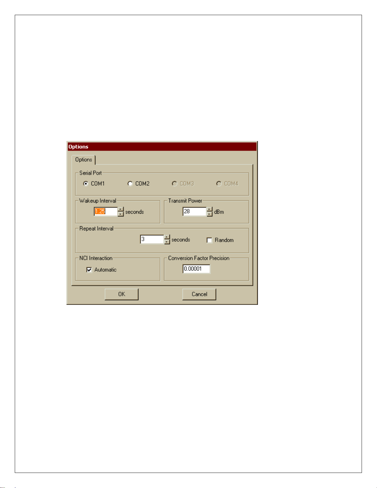
3.2. NCTT Setting:
Using the PC, star t the NCTT program.
Connect the FS U (Field Service Unit) with v ersion 2 commu nications IC (S ilico nians) to the PC.
Select “Setting” ! “Option”:
Serial Port: = Select appropriate Serial Port
Wakeup Interval = 1.25 Sec
Transmit Power = 28 dBm
Repeat Interval = 3 Sec (Min.); Unchecked “Random”
NCI Int e r a ct i o n = Che ck e d “Aut o m at i c”
Conversion Factor = 0.00001
FIGURE 1
Select “O.K.”, then setting NCTT for C&I Electric Communications:
Document Type: Test Procedure
Equipment Name: Innovatec C and I Electric
Author: Dithien V. Ho, RF Design Engineer.
Page 8 of 24
Page 9

3.3. C&I Electric Communi cations and Func tional Test
3.3.1. General device setup in NCTT:
For “DEVICE”, select “Electric IMU” and “Device ID” select “7”
For “TRANSMIT”, select “CHANNEL”= 0 (Default for untested Relay PCA)
The following Transmit options are “unchecked”:
“Auto Repeat”
“Scan”
“Wakeup/IMU”
(The untested Relay UUT Communication Channel defaults initially to Channel 0; if unable to establish a
commu nications link betwe en the FSU and the R elay U U T, try to scan all c hannels for the UUT. Select
“Query Serial Numbers” message typ e, “S elect Scan ”, an d press “Transmit”, then obs erve the reply
message to iden tify the R elay comm unications c hanne l s etting. )
FIGURE 2
Document Type: Test Procedure
Equipment Name: Innovatec C and I Electric
Author: Dithien V. Ho, RF Design Engineer.
Page 9 of 24
Page 10

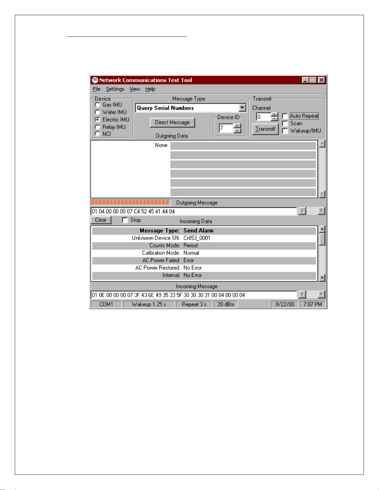
3.3.1. [Query Serial Number]
Select Query Serial Numbers and select “Transmit!”
Obs erver for the “Inc o m ing M es sage”, m ak e sure t he FSU (Field Servic e Unit) are commu nicating with
the UUT, and reporting the correct serial number for attached Meter (Either Landis & Gyr, Vectron or
applicable Devic e)
FIGURE 3
METER S/N REPORTED: ______________________
C&I DEVICE S/N REPORTED: ______________________
Document Type: Test Procedure
Equipment Name: Innovatec C and I Electric
Author: Dithien V. Ho, RF Design Engineer.
Pass__Fail___
Page 10 of 24
Page 11

3.3.2. [Set S eri al Number]
Set “Electric U SN” = Type in the C& I Serial Nu m ber then press “ T ransmit”
Make sure to obtain a “Acknowledgement Message “ reply from Incoming Data
Pass__Fail___
FIGURE 4
Document Type: Test Procedure
Equipment Name: Innovatec C and I Electric
Author: Dithien V. Ho, RF Design Engineer.
Page 11 of 24
Page 12
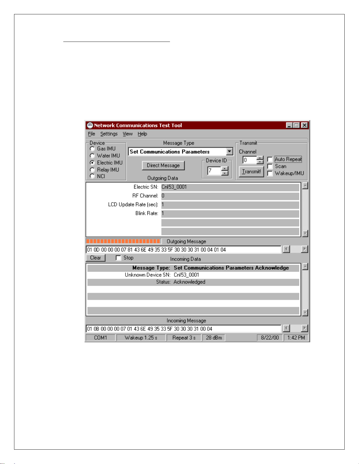
3.3.3. [Set Commu nication P arameters]
RF CHANNEL = INITIAL CHANNEL
LCD U PDATE RATE = 1
BLIN K RATE = 1
Press “TRANMI T”
Make sure to obtain a “Acknowledgement Message “ reply from Incoming Data
Pass__Fail___
FIGURE 5
Document Type: Test Procedure
Equipment Name: Innovatec C and I Electric
Author: Dithien V. Ho, RF Design Engineer.
Page 12 of 24
Page 13
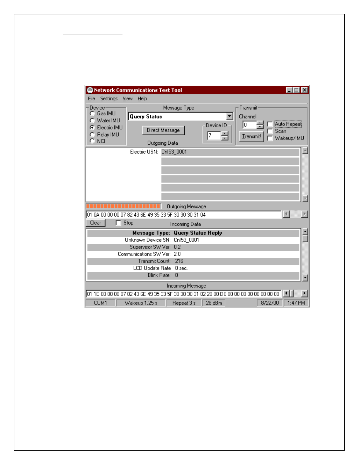
3.3.4. [Query Status]
Select “Query Status for Message Type” then press “Transmit”
Make sure to obtain a reply from Incoming Data
Pass__Fail___
FIGURE 6
Document Type: Test Procedure
Equipment Name: Innovatec C and I Electric
Author: Dithien V. Ho, RF Design Engineer.
Page 13 of 24
Page 14
4. Fin al Assembly Test
The following t es t is to be per for m ed after the PCA Assem bly has been tested and install into appropriat e Relay
housing unit.
4.1. General Test
Repeat step 3.3.2. and step 3.3.3., if necessary.
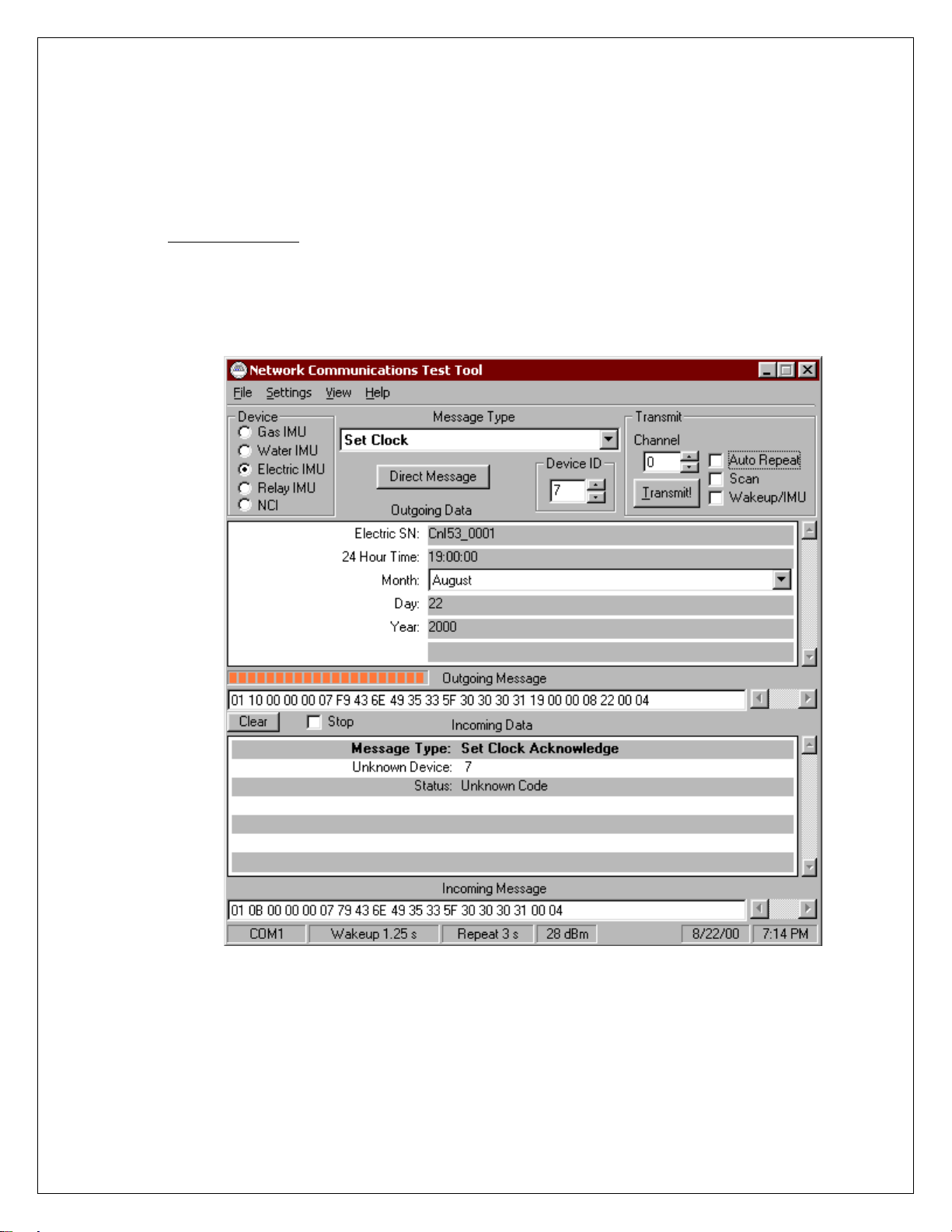
4.1.1. [Set Cloc k ]
Select “S et Clock ” mess age, enter the app licable data th en p ress “Tr an s mit”
Obs erve “Acknowled ged Mess age “ reply in I ncom ing Data (See Figu re 7)
Pass__Fail__
FIGURE 7
Document Type: Test Procedure
Equipment Name: Innovatec C and I Electric
Author: Dithien V. Ho, RF Design Engineer.
Page 14 of 24
Page 15

4.1.2. [Quer y C lo ck]
Select “Qu ery Clo ck” messag e, enter t he appro priate Relay Serial Nu m ber,
and press “Transmit”
Observe “Acknowledged Message” reply in the Incoming Data fields (See Figure 8)
Verify Calendar an d Clock settings.
Pass__Fail__
FIGURE 8
Document Type: Test Procedure
Equipment Name: Innovatec C and I Electric
Author: Dithien V. Ho, RF Design Engineer.
Page 15 of 24
Page 16

4.2. Alarms Test:
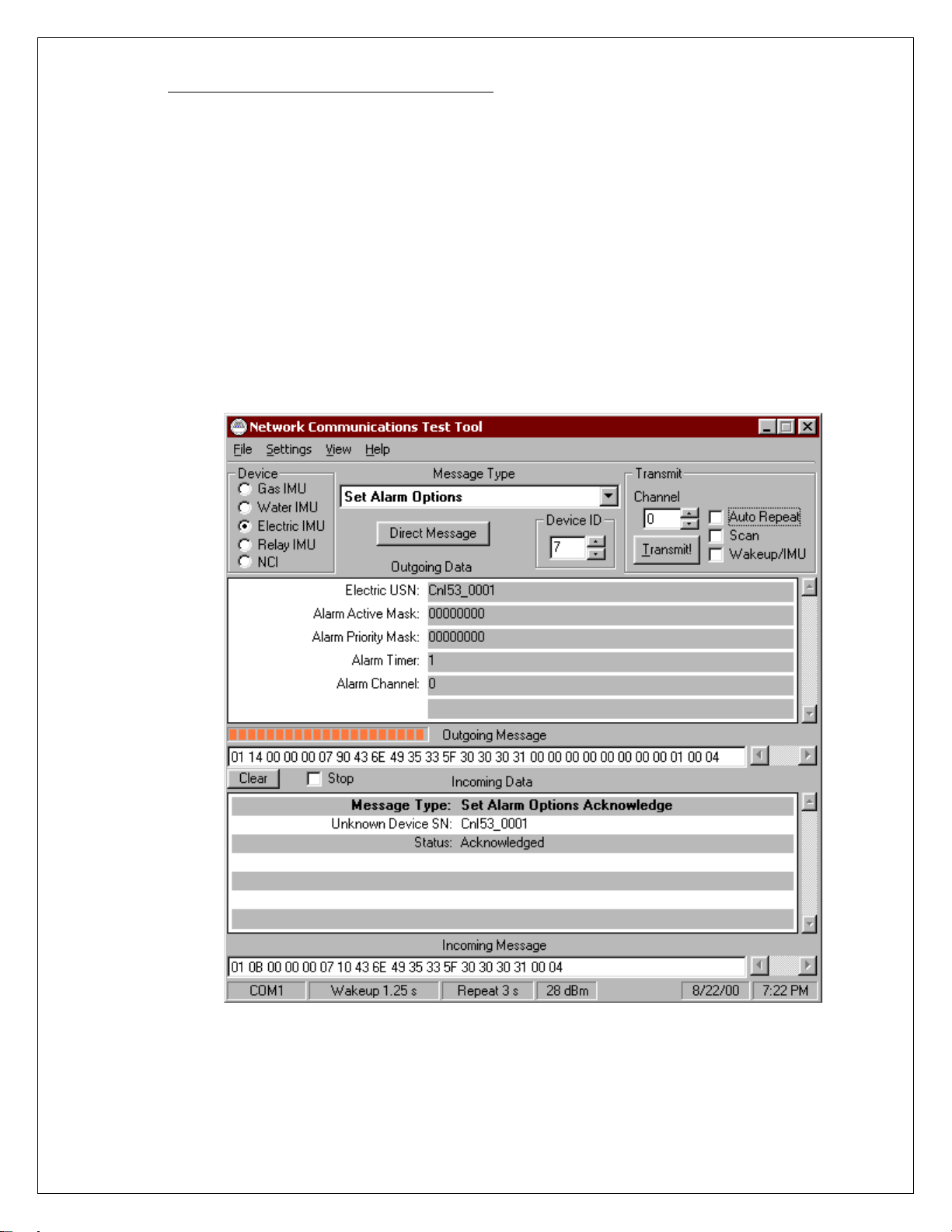
4.2.1. [Set Alarm Option]
Electric USN = UUT Serial Number
Set Alarm Active Mask = FFFFFFFF (8)
Set Alarm Priority Mask = FFFFFFFF (8)
Alarm Timer = 1 (Optional)
Alarm Channel = INITIAL CHANNEL (Same as Communications Channel)
Pass__Fail___
FIGURE 9
Document Type: Test Procedure
Equipment Name: Innovatec C and I Electric
Author: Dithien V. Ho, RF Design Engineer.
Page 16 of 24
Page 17

4.2.2. Tamper Alarm F u nction Test:
Open the C&I UUT cover (Will release the Tamper Switch)
Verify the Tam per Alarm message is sent
Pass__Fail___
FIGURE 10
Document Type: Test Procedure
Equipment Name: Innovatec C and I Electric
Author: Dithien V. Ho, RF Design Engineer.
Page 17 of 24
Page 18
4.2.3. Power Failure Alarm Function Test:
Disconnect the ac power to the C&I UUT; v er ify the Pow er Failure Alarm M es sage is sent
Pass__Fail___
FIGURE 11
Document Type: Test Procedure
Equipment Name: Innovatec C and I Electric
Author: Dithien V. Ho, RF Design Engineer.
Page 18 of 24
Page 19

4.2.4. Power Restore Alarm F u nction Test
Re-connec t the ac power to the C&I UUT; v erify the P o wer Failur e Restore Status Rep ort
Pass__Fail___
FIGURE 12
Document Type: Test Procedure
Equipment Name: Innovatec C and I Electric
Author: Dithien V. Ho, RF Design Engineer.
Page 19 of 24
Page 20
4.2.5. Disabling Alarm Transmit Func tion Test
Repeat step 4.2.1 and set “Alarm Active Mask” and “Alarm priority Mask” to 0:
Electric USN = UUT Serial Number
Set Alarm Active Mask = 00000000 (8)
Set Alarm Priority Mask = 00000000 (8)
Alarm Timer = 1 (Optional)
Alarm Channel = INITIAL CHANNEL (Same as Communications Channel)
4.2.5.1.Activate “Tamper” switch; observe for n on e alarm send message transmits.
4.2.5.2. Disconnect AC power; observe for n one alarm send message transm its.
4.2.5.3. Reconnect AC powers; observe for none alarm send message transmits.
Pass__Fail___
FIGURE 13
Document Type: Test Procedure
Equipment Name: Innovatec C and I Electric
Author: Dithien V. Ho, RF Design Engineer.
Page 20 of 24
Page 21
4.3. Actuators Test:
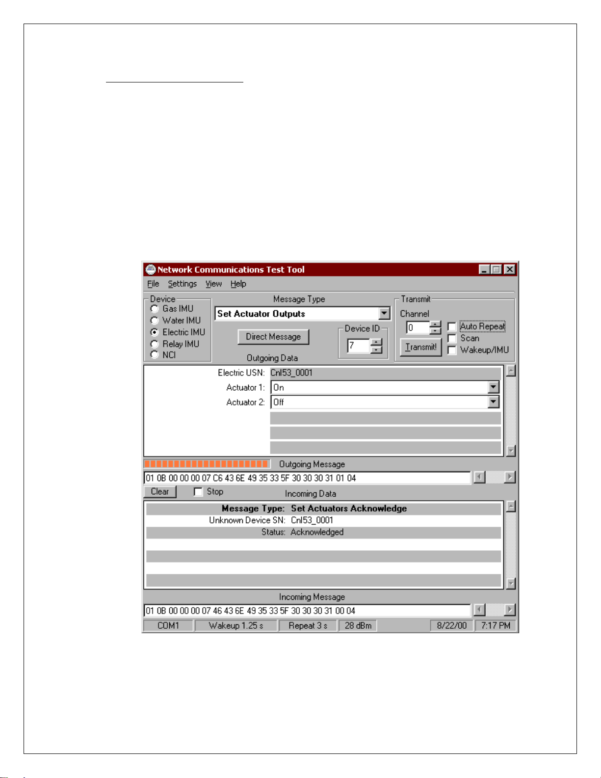
4.3.5. [Set Actuator 1 Outp ut]
Type in Electric USN = C&I UUT Serial Number
Set Actuator 1 = ON
Set Actuator 2 = OFF
Press “Transmit”
Make sure to obtain a “Acknowledgement Message “ reply from Incoming Data
Use DVM to verify between Pin 1, J10 (Actuator 1 Output) and Pin 3, J10 (Actuator 1) Common
are “Closed”
Use DVM to verify between Pin 2, J10 (Actuator 2 Output) and Pin 4, J10 (Actuator 2) Common
are “Open ”
Pass__Fail___
FIGURE 13
Document Type: Test Procedure
Equipment Name: Innovatec C and I Electric
Author: Dithien V. Ho, RF Design Engineer.
Page 21 of 24
Page 22

4.3.6. [Set Actuator 2 Outp ut]
Type in Electric USN = C&I UUT Serial Number
Set Actuator 1 = OFF
Set Actuator 2 = ON
Press “Transmit”
Make sure to obtain a “Acknowledgement Message “ reply from Incoming Data
Use DVM to verify between Pin 1, J10 (Actuator 1 Output) and Pin 3, J10 (Actuator 1) Common
are “Open ”
Use DVM to verify between Pin 2, J10 (Actuator 2 Output) and Pin 4, J10 (Actuator 2) Common
are “Close”
Pass__Fail___
FIGURE 14
Document Type: Test Procedure
Equipment Name: Innovatec C and I Electric
Author: Dithien V. Ho, RF Design Engineer.
Page 22 of 24
Page 23

4.4. Battery Power Sustain Test:
4.4.5. Disconnect the ac power to the C&I UUT
4.4.6. [Query Serial Number]
Verify to obtain the correct Serial Number report for the C&I UUT.
Pass__Fail___
FIGURE 15
Document Type: Test Procedure
Equipment Name: Innovatec C and I Electric
Author: Dithien V. Ho, RF Design Engineer.
Page 23 of 24
Page 24

5. Shipping Preparation:
• IMPORTANT!:
• Mec hanical Inspection:
Inspect all harware, screw and nut, wires and cables for propper fitting.
• Cosmetic Inspection:
In spect for cosmetic defective.
Make sure to disconnect the hook-up wire fr om the Battery charger to the
Positiv e (+) terminal of the b attery!
Battery Disconnect Check: Initial_____
Document Type: Test Procedure
Equipment Name: Innovatec C and I Electric
Author: Dithien V. Ho, RF Design Engineer.
Page 24 of 24
 Loading...