

Page 1

T
60W Endpoint
Installation Guide
Page 2
Identification
60W Endpoint Installation Guide
PUB-0771-001 Rev. A 01/06
Trademark Notice
Itron is a registered trademark of Itron, Inc. All other product names and logos in this document are used for identification
purposes only and may be trademarks or registered trademarks of their respective companies.
Patent Notice
US and foreign patents pending.
Copyright Notice
Y our company has the right to reproduce this contract document provided th at such reproduction shall be subject to the same use
and disclosure restrictions contained in the Confidentiality and Non-Disclosure paragraphs in the Sales Contract.
© 2005 Itron, Inc. All rights reserved.
Compliance Statement
This equipment has been tested and found to comply with the limits, pursuant to Part 15 of the FCC Rules. These limits are
designed to provide reasonable protection against harmful interference in a residential installation. Operation is subject to the
following conditions:
• This device may not cause interference.
• This device must accept any interference that may cause undesired operation of the device.
Complies with IC: R.S.S.-210
Transportation Classification
The Federal Aviation Administration prohibits operating transmitters and receivers on all commercial aircraft. When powered,
endpoints are considered operating transmitters and receivers and cannot be shipped by air.
Product Returns
To comply with FCC, UN, and Department of Transportation regulations, all units must be returned in their original
packaging following Itron’ s RMA process. Bubble-up transmission must be disabled prior to shipping. If you are unable to
disable the transmitter or provide original packaging, contact Itron Customer Care.
Repairs and Modifications
WARNING! Attempts to repair this device by unauthorized personnel may subject the person to shock hazard if removal
of protective covers is attempted. Unauthorized repair may void the warranty and/or maintenance contract with your
company.
WARNING! This unit cannot be modified and is not repairable. Modification of this devi ce could cause non-compliance
with FCC rules. Attempts to modify this device will void the warranty.
Lithium Batteries
WARNING! Follow these procedures to avoid injury to yourself or others.
• The lithium battery may cause a fire or chemical burn if it is not disposed of properly.
• Do not recharge, disassemble, heat, or incinerate the lithium battery.
• Keep the lithium battery away from children.
• Replace the lithium battery only with batteries meeting Itron specifications. Any other battery may cause a fire or
explosion
Suggestions
If you have comments or suggestions on how we may improve this document, send them to:
• Mail: Itron, Inc.; Attention: Customer Care; 2818 N. Sullivan Road; Spokane, WA 99216
• E-mail: support@itron.com
• Phone: 1-800-635-8725
ii 60W Endpoint Installation Guide
PUB-0771-001 Rev. A 01/06
Page 3

Contents
List of Procedures. . . . . . . . . . . . . . . . . . . . . . . . . . . . . . . . . . . . . . . . . . . v
Before You Begin . . . . . . . . . . . . . . . . . . . . . . . . . . . . . . . . . . . . . . . . . . vii
Overview . . . . . . . . . . . . . . . . . . . . . . . . . . . . . . . . . . . . . . . . . . . . . . vii
How This Document is Organized . . . . . . . . . . . . . . . . . . . . . . . . . . . vii
Related Documents . . . . . . . . . . . . . . . . . . . . . . . . . . . . . . . . . . . . . . vii
Documentation Conventions . . . . . . . . . . . . . . . . . . . . . . . . . . . . . . . vii
Chapter 1 Getting Started. . . . . . . . . . . . . . . . . . . . . . . . . . . . . . . . . . . . . . . . . . . . . . 1
About the 60W Endpoint . . . . . . . . . . . . . . . . . . . . . . . . . . . . . . . . . . . . . . . 1
Overview . . . . . . . . . . . . . . . . . . . . . . . . . . . . . . . . . . . . . . . . . . . . . . 1
Battery Life. . . . . . . . . . . . . . . . . . . . . . . . . . . . . . . . . . . . . . . . . . . . . . 1
Installation Options. . . . . . . . . . . . . . . . . . . . . . . . . . . . . . . . . . . . . . . . 1
Included Materials. . . . . . . . . . . . . . . . . . . . . . . . . . . . . . . . . . . . . . . . . . . . 2
Materials Not Included. . . . . . . . . . . . . . . . . . . . . . . . . . . . . . . . . . . . . . . . . 2
Installation Process Overview. . . . . . . . . . . . . . . . . . . . . . . . . . . . . . . . . . 3
Compatible Registers . . . . . . . . . . . . . . . . . . . . . . . . . . . . . . . . . . . . . . . . 4
Chapter 2 Installing the 60W Endpoint. . . . . . . . . . . . . . . . . . . . . . . . . . . . . . . . . . . 7
Step 1: Mounting the 60W (Using one of the following mounting techniques,
mount the 60W in the water-pit vault) . . . . . . . . . . . . . . . . . . . . . . . 7
Rod Mount
Wall (pit vault) Mount
Pipe Mount
Through-lid Mount
Step 2: Connecting the 60W to the water register. . . . . . . . . . . . . . . . . . . 17
Step 3: Verify that the 60W is operating properly . . . . . . . . . . . . . . . . . . . 21
Appendix A: Wiring for registers that do not
have a factory attached cable . . . . . . . . . . . . . . . . . . . . . . . . . . . . . . . . . . 22
Contents iii
PUB-0771-001 Rev. A 01/06
Page 4

iv 60W Endpoint Installation Guide
PUB-0771-001 Rev. A 01/06
Page 5

List of Procedures
Attaching a Cable Tie to the Connector . . . . . . . . . . . . . . . . . . . . . . . . . . . . . . . . . 6
Installing with the Rod Mount . . . . . . . . . . . . . . . . . . . . . . . . . . . . . . . . . . . . . . . . . 8
Installing a Wall Mount . . . . . . . . . . . . . . . . . . . . . . . . . . . . . . . . . . . . . . . . . . . . . 12
Installing on a Pipe. . . . . . . . . . . . . . . . . . . . . . . . . . . . . . . . . . . . . . . . . . . . . . . . 14
Installing Through-Lid. . . . . . . . . . . . . . . . . . . . . . . . . . . . . . . . . . . . . . . . . . . . . . 16
Connecting an Inline Connector. . . . . . . . . . . . . . . . . . . . . . . . . . . . . . . . . . . . . . 17
Appendix A: Wiring for Registers that Do Not Have a Factory
Installed Inline Connector. . . . . . . . . . . . . . . . . . . . . . . . . . . . . . . . . . . . . . . . . . . 22
Attaching the Inline Connector to the Neptune ProRead and ARB V Registers. . 22
PUB-0771-001 Rev. A 01/06
List of Procedures v
Page 6

vi 60W Endpoint Installation Guide
PUB-0771-001 Rev. A 01/06
Page 7

Before You Begin
Overview The 60W is available with either a 5’ length of cable (not terminated) or with an
inline connector (attached to approx. 7’’ of cable) and will interface with several
encoded (absolute) registers. This document describes the installation of the
60W endpoint, including rod mount, wall mount, pipe mount and through-lid
installations.
How This Document
is Organized
Documentation
Conventions
This document is organized as follows.
Chapter Description
Chapter 1.
Getting Started
Provides an overview of the 60W endpoint installation, including installation options, siting, and
required tools.
Chapter 2.
Installing the 60WP
Endpoint
Provides step-by-step instructions for wiring the
endpoint to a register and installing the endpoint
using the rod mount, on a wall or similar surface,
or on a pipe.
This document uses the following conventions.
Convention Example
Itron product part numbers
are noted in parentheses.
To install the endpoint (ERW-0771-2XX), do
the following steps.
Hypertext links are blue. See Contents on page iii for the complete table
of contents.
The last line in a table is
defined by a thick gray
line.
Note the thick gray line belo w this row. If the
table continues on another page, the column
headings are repeated on each page.
CAUTION This type of note warns the user that failure to heed the information in
the note could result in loss of data. Be sure to carefully read a CAUTION note
and heed the advice/instructions.
WARNING! This type of note is used to warn of potential p hysical harm
to the user or hardware. It is critical that you pay strict attention to
WARNING notes, read the information carefully, and heed the
advice/instructions.
Before You Begin
PUB-0771-001 Rev. A 01/06
vii
Page 8

viii 60W Endpoint Installation Guide
PUB-0771-001 Rev. A 01/06
Page 9

Chapter 1
Getting Started
About the 60W Endpoint
Overview The 60W water endpoint is an AMR module that collects consumption and
tamper information and reports in a bubbleup fashion. Approximately every 8
seconds, the 60W transmits a standard consumption message (SCM) at approximately +10dBm between 910-920 MHz. The 60W supports protocols for a
variety of meter manufacturer's registers, including but not limited to: AMCO,
Badger, Hersey, Neptune, and Sensus.
The 60W features the following capabilities:
Leak Detection The 60W will continually compare hourly register
•
readings. The 60W will report in the SCM if a zero consumption (equal to
previous read) doesn’t occur over a period of seven years
T amper Indicators To minimize the possibility of theft, the 60W features
•
cut cable tamper reporting, as well as a security seal to indicate physical
tampering. Cut cable is reported when the cable has been cut or disconnected from the register or the endpoint.
•
Reverse Flow Detect ion The 60W will compare the hourly read with the
previous read. If the current read is less than the previous read the 60W will
report in the SCM that this occurred.
Battery Life Powered by a non-replaceable long life dual lithium battery pack, the 60W end-
point has an expected battery life of 20 years.
Installation Options The 60W endpoint may be installed in the following ways:
•
Rod Mount Rod mount installation allows the endpoint to be mounted to
a 3/8” outside diameter length of pipe, rebar, or conduit that has been
driven at least 12 inches into the ground at the bottom of the meter pit..
Wall Mount Wall mount installation attaches the endpoint to a wall or
•
other surface within a meter pit..
•
Pipe Mount The pipe mount (vertical pipe only) option allows the end-
point to be installed on a pipe near the meter rather than on a wall surface.
•
Through Lid Used in conjunction with the through-lid mounting kit, this
option allows the endpoint to be mounted up into a hole (1 7/8”) in a pit lid.
Chapter 1 - Getting Started 1
PUB-0771-001 Rev. A 01/06
Page 10
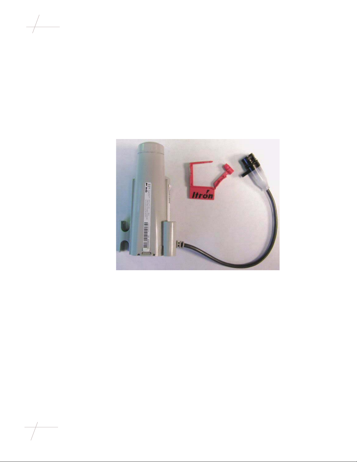
Included Materials
Included Materials
The following materials are supplied by Itron:
• 60W endpoint with inline connector (connector includes a protective
• 60W endpoint with a 5’ cable (This configuration allows for connection
• Connector cables in 5-foot and 25-foot lengths. Itron typically supplies
Figure 1: 60W Endpoint
cover) and security seal.
or
directly to the register terminals.).
these cables to the meter manufacturer for potting to the register.
Materials Not Included
2 60W Endpoint Installation Guide
PUB-0771-001 Rev. A 01/06
• Screws, Rebar Cable Ties, Hammer, Tape Measure and Screwdriver.
• Through Lid Mounting pieces, these can be ordered in quantities o f ?? and
include a Through Lid mount, Lid mount clamp and cable ties
Page 11

Installation Process Overview
Mount
60W
Installation Process Overview
Inline
Connector
Yes
Put u n it in
ins t allation
mode
Co n n e c t in line
connector
No
Mount register
according to
Manufacturers
recommended
procedure
Verify the 60W
is operating
properly
Chapter 1 - Getting Started 3
PUB-0771-001 Rev. A 01/06
Page 12

Compatible Registers
Compatible Registers
The following water meter registers are compatible with the 60W.
• AMCO Scancoder
•AMCO InVision
• Badger ADE (To be released at a later date)
• Hersey Translater (To be released at a later date)
• Sensus ICE, ECR, WP , TR-PL, and AMR System (T o be released at a later
date)
• Neptune ProRead and ARB V (formerly Schlumberger) (T o be released at
a later date)
The following figures show the cable assembly required for each installation
Figure 2: AMCO InVISION
4 60W Endpoint Installation Guide
PUB-0771-001 Rev. A 01/06
Figure 3: AMCO Scancoder with factory assembled inline connector and cable
Page 13

Compatible Registers
Figure 4: Badger ADE with factory assembled inline connector and cable
Figure 5: Hersey T ranslator with factory assembled inline connector and cable
Figure 6: For Neptune ProRead and ARB V, use the inline connector and cable
assembly with unterminated wires
Chapter 1 - Getting Started 5
PUB-0771-001 Rev. A 01/06
Page 14

Compatible Registers
Figure 7: Sensus ICE, ECR WP, TR-PL, or AMR System with factory installed
inline connector assembly
NOTE If the 60W endpoint and register are not being installed at the same time,
the protective connector cover on the endpoint to be installed must be secured
using cable tie MSE-0005-002. These cable ties can be ordered from Itron; they
are not shipped with the 60W endpoint. The protective cover (on the endpoint
side) is only meant to be used in the field for up to one year.
Attaching a Cable
Tie to the Connector
Follow the steps below to attach a cable tie to the connector.
Figure 8: Cable Tie (MSE-0005-002)
NOTE Follow utility recommendations for removing ties from cable assemblies.
• To install a cable tie, thread it through the holes in the connector and protective cover, then through the eye of the cable tie. Then pull the cable tie
tight to secure it, as shown below.
Figure 9: Cable tie on a 60W connector
Figure 10: Cable tie on register connector
6 60W Endpoint Installation Guide
PUB-0771-001 Rev. A 01/06
Page 15

Chapter 2
Installing the 60WP Endpoint
This chapter shows you how to install the 60W endpoint, including mounting,
electrical connection and verify operation.
Step 1: Mounting the 60W
Use one of the following procedures to mount the 60W.
• Rod Mount Installation ................................................................. 4
• Wall (Pit Vault) Mount Installation ............................................... 8
• Pipe Mount Installation .............................................................. 10
• Through-Lid Mount Installation ..................................................12
Chapter 2 - Installing the 60WP Endpoint 7
PUB-0771-001 Rev. A 01/06
Page 16

Rod Mount Installation
Rod Mount Installation
Overview The 60W endpoint can be mounted below the pit lid on a customer-supplied rod.
WARNING! The installer is responsible for ensuring that the area where the rod
will be installed is free from other pipes, wires, or facilities that may be damanged by driving a rod into the ground.
Local codes must be followed in the following procedure.
Required Tools and
Hardware
The following items are required for this type of installation.
• Hammer or sledge hammer
• Rod (Steel rod stock, PVC, or conduit): 3/8" outside diameter.
• Tape measure
Figure 1: Bottom view of the rod mount, showing the 3/8" diameter rod hole
3/8" Rod Mount
8 60W Endpoint Installation Guide
PUB-0771-001 Rev. A 01/06
Page 17

Rod Mount Installation
Installing with the
Universal Rod
Mount
To perform this type of installation, follow the steps below.
Step Action
1.1 Remove the pit lid. Inspect the area to make sure there are no cables,
pipes, or other obstructions.
1.2 Measure the depth of the pit, from the top lip (which the lid rests on) to
the bottom of the pit.
1.3 T o properly mount, the rod (rebar , PVC, or conduit) must be cut at least
7" longer than the measured depth of the pit. For example, if the pit is
36" deep, the rod must be at least 40" long.
Cut the rod to the appropriate length.
Chapter 2 - Installing the 60WP Endpoint 9
PUB-0771-001 Rev. A 01/06
Page 18

Rod Mount Installation
Step Action
1.4 Without touching the meter body or adjacent pi pes, position the rod as
close to the center of the pit as possible, and then drive it into the ground
at least 12".
• The rod must remain vertical.
• The top of the rod should be 5" below the lip of the pit (which the
lid rests on).
1.5
NOTE For the best RF performance, the top of the endpoint must be
perpendicular to the pit lid, and be within 1" to 3" below the pit lid once
the installation is complete.
NOTE Due to varying soil conditions, Itron recommends the rod be
driven into the ground at least 12".
3/8" Rod Mount
10 60W Endpoint Installation Guide
PUB-0771-001 Rev. A 01/06
Page 19

Rod Mount Installation
Step Action
1.6 Connect the 60W endpoint to the register via the inline connector,
making sure the O rings are properly seated and not bulging out of the
connector. Install the endpoint and rod mount assembly onto the rod,
making sure the rod goes into the proper hole of the adapter.
1.7 When the installation is complete, the top of the endpoint should be perpendicular to and 1" to 3" below the underside of the lid. The endpoint
must not contact the pit structure or lid.
CAUTION If the module installation is too high, too low, or touching,
disassemble and relocate the rod in the pit.
Chapter 2 - Installing the 60WP Endpoint 11
PUB-0771-001 Rev. A 01/06
Page 20

Wall Mount Installation
Wall Mount Installation
Before You Begin Select a mounting location inside the pit. Itron recommends mounting a 60W
endpoint as close as possible to the top of the pit, and away from any metal
objects.
Required Tools and
Hardware
Installing on a
Surface
Wall mount installation requires the following tools and hardware:
• Drill and bits for expected surface mounts
• #2 Phillips screwdriver
• Mounting screws.
Figure 2: Wall Mount materials
Use the wall mount installation kit to install a 60W endpoint on a wall or other
flat surface in a meter pit.
• When mounting the endpoint to the wall in a rectangular pit box, use a flat
wall as the mounting surface.
• When mounting the endpoint to the wall in a round pit box, ensure that the
center spacing of the pilot holes is on-center and that the holes are straight
and perpendicular to where the endpoint will attach. When the endpoint is
installed, the mounting tabs will not be completely flush against the wall
because of the curvature of the surface. In this environment, care should be
taken to not over-tighten the mounting screws; the mounting tabs on the
endpoint may break as a result.
To install the 60W endpoint, follow the steps below.
12 60W Endpoint Installation Guide
PUB-0771-001 Rev. A 01/06
Step Action
1.1 Select an installation location for the endpoint in the meter box.
1.2 Pre-drill two 3/32" holes into the wall or other surface. Position the
pilot holes vertically on 3/4" centers.
Page 21

Wall Mount Installation
Step Action
1.3 Position the 60W endpoint in an upright position, over the pilot holes
as shown.
IMPORT ANT! Any other endpoint position may negatively affect radio
performance and battery life.
1.4 Screw the endpoint to the wall until snug using the supplied mounting
screws.
Chapter 2 - Installing the 60WP Endpoint 13
PUB-0771-001 Rev. A 01/06
Page 22

Pipe Mount Installation
Pipe Mount Installation
Before You Begin Select a mounting location. Itron recommends mounting the 60W endpoint as
close to the top of the pit as possible, and also away from any metal objects.
Required Tools and
Hardware
You will need two 15" nylon cable ties (574-9008-007)
• Pliers
Installing on a Pipe To install the endpoint on a pipe, follow the steps below. .
Step Action
1.1 Select an installation location.
1.2 Place first cable tie around the bottom of the 60W endpoint so that it
will attach to the pipe in an upright positition.
1.3 Place second cable tie around the top of the 60W endpoint so that it will
attach to the pipe in an upright positition.
14 60W Endpoint Installation Guide
PUB-0771-001 Rev. A 01/06
Page 23

Pipe Mount Installation
Step Action
1.4 Position the 60W endpoint in an upright position as shown.
IMPORT ANT! Any other endpoint position may negatively affect radio
performance and battery life.
Chapter 2 - Installing the 60WP Endpoint 15
PUB-0771-001 Rev. A 01/06
Page 24

Through-Lid Mount Installation
Through-Lid Mount Installation
16 60W Endpoint Installation Guide
PUB-0771-001 Rev. A 01/06
Page 25

Step 2: Connecting the 60W to the water meter register
Step 2: Connecting the 60W to the water meter register
Note: Skip this step if an inline connector is not being used and the 60W is
already connected to the water meter register. Follow the manufacturer’ s recommended procedure for installing the water register on meter.
Connecting an Inline
Connector
The following section shows you how to attach the inline connector assembly.
Step Action
2.1 Remove the protective cover from the connector by twisting the two
halves in opposite directions, and then pull the halves apart.
Register or
reed switch
connector
Endpoint
connector
CAUTION If any of the following conditions occur, do not install the
endpoint:
• If any of the three pins are damaged or missing
• The O ring is missing
• The cable is cut
IMPORTANT Make sure the connector halves are clean and dry before
assembly.
Chapter 2 - Installing the 60WP Endpoint 17
PUB-0771-001 Rev. A 01/06
Page 26

Step 2: Connecting the 60W to the water meter register
Step Action
2.2 Use shorting plug to initiate installation mode (optional). This will put
the 60W in a mode where by it will read the register every minute and
transmit every second for the first 15 minutes.
18 60W Endpoint Installation Guide
PUB-0771-001 Rev. A 01/06
Page 27

Step 2: Connecting the 60W to the water meter register
Step Action
2.3 Connect the endpoint to the register cable connector.
• Holding the connectors by the back-shells, rotate one end to align
the keyed slots. Push until snug.
• Slide the black coupling over the O-ring. Make sure the O-ring
stays seated. If the O-ring does not stay seated, disconnect and try
again
• Twist to align the two tabs.
Chapter 2 - Installing the 60WP Endpoint 19
PUB-0771-001 Rev. A 01/06
Page 28

Step 2: Connecting the 60W to the water meter register
Step Action
2.4 Install the security seal as shown. Push it until it snaps into place.
NOTE For future servicing of either the meter or endpoint, break the
security seal by pulling apart. Original protective connector covers can
be reused if kept clean and dry. Install a new security seal after servicing either device. To order more parts, see the Water Endpoint
Ordering Guide (PUB-0063-001).
IMPORTANT Be sure to protect connectors with protective covers. Do
not leave an exposed connector in the field.
20 60W Endpoint Installation Guide
PUB-0771-001 Rev. A 01/06
Page 29

Step 3: Verify that the 60W is operating properly
Step 3: Verify that the 60W is operating properly
Step Action
3.1 Using a G5R or FC200 verify that the 60W can be read and is reporting
the correct consumption.
Note: If the 60W is in "Installation mode" it will read the register every
minute, if it’s in "Normal mode" it will read the register every hour.
This needs to be kept in mind when comparing the 60W for consumption to the water meter register index.
Note: ReadOne Pro’s, FS2PN and FS3PN readers should not be used to
read the 60W . These readers do not keep their receivers on long enough
or at the right frequency channels
Chapter 2 - Installing the 60WP Endpoint 21
PUB-0771-001 Rev. A 01/06
Page 30

Appendix A
Appendix A
Attaching the Inline
Connector to the
Neptune ProRead
and ARB V Registers
Follow the steps below to attach the inline connector cable to the Neptune (formerly Schlumberger) ProRead and ARB V registers.
Figure 3: Neptune ProRead register
CAUTION Itron strongly recommends that customers contact Neptune to request
factory potting of the inline connector cable to the register to ensure a proper
seal. Should a retrofit be desired in the field, it is recommended that the register
be removed from the field and the following procedure be performed in a controlled environment.
Step Action
Acquire an inline connector and cable assembly with unterminated
1
wires. Refer to the Water Endpoint Ordering Guide (PUB-0063-001)
for more information.
22 60W Endpoint Installation Guide
PUB-0771-001 Rev. A 01/06
2 Pull the bottom edge of the wire terminal enclosure’s cover out and
down, as shown below.
Cover
IMPORTANT Failure to follow steps 3 and 4 will void the Itron warranty.
Page 31

Appendix A
Step Action
3 Connect the cable wires to the register screw terminals as shown below.
IMPORTANT Be sure to bend the wires around the scews in a clockwise
direction (as viewed from the top). Failure to do so may allow some or
all of the wire strands to come out from under the screw heads as you
tighten them.
• Connect the black cable wire to
• Connect the bare cable wire to
NOTE Make this bare wire short so that it pulls the cable close to
Screw 1.
Screw 2.
the terminals and away from the outer jacket.
• Connect the red cable wire to
Screw 1
(black
wire)
Screw 2
(bare
wire)
Screw 3.
Screw 3
(red
wire)
For strain relief,
position the cable
between these
posts.
Chapter 2 - Installing the 60WP Endpoint 23
PUB-0771-001 Rev. A 01/06
Page 32

Appendix A
Step Action
4 Thoroughly cover the cable wires and register screw terminals with the
Neptune-approved Dow Corning Compound #4 sealant. If necessary,
contact Neptune for a list of suppliers in your area that carry this
sealant.
IMPORTANT Make sure all screw heads, the potting well, and the end
of the cable are fully encapsulated with sealant.
Cover these
areas with
sealant
5 Put the terminal enclosure cover back on the register.
6 When you have finished, the register and cable should look like this:
IMPORTANT Excess sealant should be visible and extrude from the
cable connection when the cover is mounted.
Excess sealant should
extrude here
24 60W Endpoint Installation Guide
PUB-0771-001 Rev. A 01/06
 Loading...