

Page 1

Water Solutions
100W-R and 100WP-R Datalogging ERT
Module Installation Guide
TDC-0951-004
Page 2

Identification
Compliance Statement
This equipment complies with policies RSS-210 and RSS-GEN of the Industry Canada rules.
Operation is subject to the following two conditions:
(1) this device may not cause interference, and
(2) this device must accept any interference, including interference that may cause undesired
operation of the device.
Déclaration de conformité
Le présent appareil est conforme aux CNR d'Industrie Canada applicables aux appareils
radio exempts de licence. L'exploitation est autorisée aux deux conditions suivantes :
(1) l'appareil ne doit pas produire de brouillage, et
(2) l'utilisateur de l'appareil doit accepter tout brouillage radioélectrique subi, même si le
brouillage est susceptible d'en compromettre le fonctionnement.
Compliance Statement Canada
Under Industry Canada regulations, this radio transmitter may only operate using an antenna of a type
and maximum (or lesser) gain approved for the transmitter by Industry Canada. To reduce potential
radio interference to other users, the antenna type and its gain should be so chosen that the equivale nt
isotropically radiated power (e.i.r.p.) is not more than that necessary for successful communication.
Déclaration de Conformité
Conformément à la réglementation d'Industrie Canada, le présent émetteur radio peut
fonctionner avec une antenne d'un type et d'un gain maximal (ou inférieur) approuvé pour
l'émetteur par Industrie Canada. Dans le but de réduire les risques de brouillage
radioélectrique à l'intention des autres utilisateurs, il faut choisir le type d'antenne et son
gain de sorte que la puissance isotrope rayonnée équivalente (p.i.r.e.) ne dépasse pas
l'intensité nécessaire à l'établissement d'une communication satisfaisante.
Warning To prevent ignition of flammable or combustible atmospheres, disconnect power before
servicing.
Warning Follow these procedures to avoid injury to yourself or others:
• The lithium battery may cause a fire or chemical burn if it is not disposed of properly.
• Do not recharge, disassemble, heat above 100° Celsius (212° Fahrenheit), crush, expose to
water, or incinerate the lithium battery. Fire, explosion, and severe burn hazard.
• Keep the lithium battery away from children.
• Replace the lithium battery only with batteries meeting Itron specifications. Any other battery
may cause a fire or explosion.
Warning ELECTROMAGNETIC COMPATIBILITY
Use only approved accessories with this equipment. Unapproved modifications or operation beyond
or in conflict with these instructions for use may void authorization by the authorities to operate the
equipment.
Warning This unit cannot be modified and is not repairable. Attempts to modify or repair this device
will void the warranty.
100W-R and 100WP-R Datalogging ERT Module Installation Guide
11/10/2011 TDC-0951-005
Copyright
© 2010 - 2011 Itron, Inc. All rights reserved.
Confidentiality Notice
The information contained herein is proprietary and confidential and provided subject to the condition that (i) it is held in confidence except to the extent required otherwise by law and (ii) it is
used only for the purposes described herein. Any third party given access to this information is similarly bound in writing.
Compliance Statement
This device complies with Part 15 of the FCC Rules. These limits are designed to provide reasonable protection against harmful interference in a residential installation. Operation is subject to
the following two conditions:
• This device may not cause harmful interference.
• This device must accept any interference that may cause undesirable operation.
This device must be permanently mounted such that it retains a distance of 20 centimeters (7.9 inches) from all persons in order to comply with FCC RF exposure lev els.
This equipment has been tested and found to comply with the limits for a Class B digital device, pursuant to Part 15 of the FCC Rules. These limits are designed to provide reasonable
protection against harmful interference in a residential installation. This equipment generates, uses, and can radiate radio frequency energy and, if not installed and used in accordance with the
instructions, may cause harmful interference to radio communications. However, there is no guarantee that interference will not occur in a particular installation.
If this equipment does cause harmful interference to radio or television reception, which can be determined by turning the equipment off and on, the user is encouraged to try to correct the
interference by one or more of the following measures:
Reorient or relocate the receiving antenna.
Increase the separation between the equipment and receiv er.
Connect the equipment into an outlet on a circuit different from that to which the receiver is connected.
Consult the dealer or an experienced radio or TV technician for help.
Trademark Notice
Itron is a registered trademark of Itron, Inc.
All other product names and logos in this documentation are used for identification purposes only and may be trademarks or registered trademarks of their respective companies.
Page 3

Transportation Classification
The Federal Aviation Administration prohibits operating transmitters and receivers on all commercial ai rcraft. When powered, ERT modules are considered operating transmitters and receivers and
cannot be shipped by air. All product returns must be shipped by ground transportation to Itron.
Suggestions
If you have comments or suggestions on how we may improve this documentation, send them to TechnicalCommunicationsManager@itron.com
If you have questions or comments about the software or hardware product, contact Itron Technical Support:
Contact
Internet: www.itron.com
E-mail: support@itron.com
Phone: 800 635 8725
Page 4

TDC-0951-005 100W-R and 100WP-R Datalogging ERT Module Installation Guide v
Proprietary and Confidential
Chapter 1 Before You Begin ........................................................................................ 1
Contents
Document Conventions ....................................................................................................................... 1
Document Purpose .............................................................................................................................. 1
How This Document is Organized ....................................................................................................... 1
Related Documents ............................................................................................................................. 2
Chapter 2 About the 100W-R and 100WP-R ............................................................... 3
100W-R and 100WP-R Models ........................................................................................................... 4
Battery Life .......................................................................................................................................... 4
100W-R and 100WP-R Transmission Modes ..................................................................................... 5
100W-R Operating Modes ................................................................................................................... 5
100WP-R Operating Modes ................................................................................................................ 6
Chapter 3 Initializing, Programming and Connecting the ERT Module ................... 7
Initializing the 100W-R ........................................................................................................................ 7
100W-R Encoder Start-up ................................................................................................................... 7
Programming the 100WP-R ................................................................................................................ 8
100WP-R Pulser Start-up .................................................................................................................... 8
Connecting the 100W-R to a Remote Meter Register ........................................................................ 9
Connecting the 100WP-R to a Remote Meter Register .................................................................... 10
Verifying 100W-R and 100WP-R ERT Module Operation ................................................................ 10
Chapter 4 Installing the 100W-R and 100WP-R ERT Modules ................................ 11
100W-R and 100WP-R ERT Module Accessories ............................................................................ 11
Installing 100W-R and 100WP-R Cable Strain Relief ....................................................................... 11
Required Materials ............................................................................................................................ 12
Attaching the Backplate ..................................................................................................................... 14
Pipe Mount Installation ...................................................................................................................... 16
Optional Leak Sensor Installation ..................................................................................................... 21
Connecting the Leak Sensor to the 100W-R and 100WP-R ERT Modules ........................... 22
Required Equipment ............................................................................................................... 23
Pipe Preparation ..................................................................................................................... 23
Remote Mount Installation ................................................................................................................. 27
Required Tools and Hardware ................................................................................................ 27
Direct-Mounting to the Meter Register .............................................................................................. 29
Page 5

Contents
TDC-0951-005 100W-R and 100WP-R Datalogging ERT Module Installation Guide vi
Proprietary and Confidential
Appendix A Using Gel-cap Connectors .................................................................... 37
Appendix B Troubleshooting .................................................................................... 39
Index ............................................................................................................................. 40
Page 6
TDC-0951-005 100W-R and 100WP-R Datalogging ERT Module Installation Guide 1
Proprietary and Confidential
Document Conventions
Convention
Example
Itron product part numbers are noted in
parentheses.
To install the ERT module (ERW-1300-XXX), do the following steps.
Hypertext links are in blue.
For more information about 100W remote ERT module models, see 100W-R and
100WP-R Models on page 4.
Note A Note indicates neutral or positive information that stresses or supplements important points
of the main text. A note supplies information that may apply only in special cases.
Caution A Caution advises users that failure to take or avoid a specified action could result in a loss
of data.
Warning A Warning advises users that failure to take or avoid a specified action could result in
physical harm to the user or the hardware.
Caution Installing a remote ERT module or an integrated 100W ERT module and meter register
in a water pit box will void the product warranty. Remote ERTs are designed for interior and
exterior (on the side of buildings) installations only. Use a pit ERT module for pit-mount
applications. (Refer to the Water Endpoint Ordering Guide PUB-0063-001).
Chapter
Description
1. Before You Begin
Information about this publication
2. About the 100W-R and 100WP-R
Overview of 100W-R and 100WP-R functionality.
3. Connecting, Initializing and
Programming
Instructions to initialize the 100W ERT module and connect the ERT module to the
register.
4. Installing the 100W-R and
100WP-R
Step-by-step ERT module installation instructions for:
Pipe mount
Optional Leak Sensor
Remote mount
Direct mount
Appendix A Using Gel-cap
Connectors
Instructions for using gel-cap connectors to connect the remote ERT module to the register.
Appendix B Troubleshooting
Tips for troubleshooting 100W ERT module operation.
C H A P T E R 1
Before You Begin
Document Purpose
This document provides installation instructions for the 100W-R and 100WP-R ERT modules including stepby-step instructions for pipe mount, remote mount, and direct mount.
How This Document is Organized
This installation guide is organized with the following chapters:
Page 7

Before You Begin
TDC-0951-005 100W-R and 100WP-R Datalogging ERT Module Installation Guide 2
Proprietary and Confidential
Related Documents
Document Description
Itron Part Number
100W and 100G ERT Tamper Reference Guide
TDC-1028-000
Field Deployment Manager Endpoint Tools Mobile Application Guide
TDC-0934-XXX
Field Deployment Manager Field Representative's Guide
TDC-0936-XXX
900 MHz Belt-Clip Radio User's Guide
TDC-0889-XXX
FC300 Getting Started Guide
TDC-0898-XXX
FC200 Series Getting Started Guide
TDC-0598-XXX
Endpoint-Link® Programming Guide
TDC-0744-XXX
Water ERT Module Ordering Guide
PUB-0063-001
Water Meter Compatibility List
PUB-0063-002
mlogonline™ Network Leak Monitoring System User Guide
TDC-0792-XXX
Note XXX designates the document revision and is subject to change without notice.
Page 8

TDC-0951-005 100W-R and 100WP-R Datalogging ERT Module Installation Guide 3
Proprietary and Confidential
The 100W-R and 100WP-R are high-power radio frequency automatic meter reading (AMR) devices that
Caution Failure to initialize the ERT module may delay the initial reading up to 1 hour. The
100WP-R module will default to a consumption value of 0 if the ERT module is not programmed
with Itron's Field Deployment Manager (FDM).
Note The 100WP-R ERT module will not report reverse flow. Incremental encoded registers do
not provide a distinguishing signal while flowing in reverse.
Note A Last Good Read Flag may be an indicator of a damaged register.
C H A P T E R 2
About the 100W-R and 100WP-R ERT Module
attach to water registers to collect consumption usage and tamper data that the ERT module transmits to a data
collection device. The ERT module operates in both bubble-up mode and two-way modes.
The 100W-R and 100WP-R ship in Factory Mode. The ERT modules acquire and transmit meter register data
within one hour following register connection. The ERT module transfers meter data immediately if the unit is
initialized with a handheld computer during installation (see Initializing, Connecting and Programming the
ERT Module on page 7).
The 100W-R and 100WP-R support protocols for a variety of meter manufacturer's registers. Refer to the
Water Meter Compatibility List (PUB-0063-002), for the list of supported meters and registers.
100W-R and 100WP-Rs feature the following capabilities:
Leak Detection and Reverse Flow Detection. 100W series ERT modules feature the same robust
features as Itron's 60 series water ERT modules to provide Leak Detection and Reverse Flow Detection.
For more information about Leak Detection and Reverse Flow Detection, see the Itron white paper
Detecting Leaks and Reverse Flow with 60 Series Endpoints.
Communication Error Indicators.
Last Good Read (LGR Flag). Indicates a communication error with the register.
100W-R encoder ERT module
If this flag is set for 24 consecutive hours, it initiates a cut cable flag in the extended tampers.
The Last Good Read Flag automatically clears after the ERT module receives a successful read
from the register.
100WP-R pulser ERT module
If the Last Good Read Flag is set two consecutive times, it initiates a Cut Cable Flag in the
extended tampers.
The Last Good Read Flag automatically clears after the ERT module receives a successful read
from the register.
Page 9

About the 100W-R and 100WP-R ERT Module
TDC-0951-005 100W-R and 100WP-R Datalogging ERT Module Installation Guide 4
Proprietary and Confidential
Extended Tamper Flag (retrievable with two-way communication).
100W Remote ERT Module Description
Itron Part Number
100W-R Encoder Remote, 10-inch flying lead
ERW-1300-213
100W-R Encoder Remote with Leak Sensor, 10-inch flying lead
ERW-1300-214
100WP-R Pulser Remote, 10-inch flying lead
ERW-1300-215
100WP-R Pulser Remote with Leak Sensor, 10-inch flying lead
ERW-1300-216
Low Battery Warning. The 100W-R and 100WP-R ERT modules include a battery life estimator. The
estimator is based on the number of data packets sent at the various power levels and the age (selfdischarge) of the ERT module. The low battery warning allows the utility to easily identify which
ERTs are nearing end-of-life in a mixed population and gives the opportunity to schedule replacement.
The low battery warning is a single flag set when the battery has less than 10% remaining capacity,
typically 2 years life remaining Battery life is evaluated daily at midnight.
Cut Cable Flag.
100W-R encoder ERT module. The Cut Cable Flag sets if the LGR Flag is active for 24 hours.
100WP-R pulser ERT module. The Cut Cable Flag sets if the LGR Flag is active for two consecutive
times.
The Cut Cable Flag remains active for 40 days in Mobile mode.
The Cut Cable Flag remains active for 24 hours in Fixed Network mode.
100W-R and 100WP-R Models
Battery Life
Powered by two non-replaceable, long-life lithium batteries, the 100W has an expected battery life of 20 years
when the ERT module operates in default Mobile or Fixed Network Operating mode. If the 100W series ERT
module is programmed for Hard to Read Mobile Mode, the battery life is reduced to 13 years. To proactively
indicate the battery has reached a <10% useful battery life, a Low Battery flag is set to indicate impending
battery failure. Battery life is 15 years for the 100WP-R when ERT module cable lengths exceed 150 feet.
Page 10

About the 100W-R and 100WP-R ERT Module
TDC-0951-005 100W-R and 100WP-R Datalogging ERT Module Installation Guide 5
Proprietary and Confidential
100W-R and 100WP-R Transmission Modes
The 100W-R and 100WP-R ERT modules can be set to transmit in fixed network, mobile high power, mobile
and handheld, or hard to read mobile and handheld mode.
Fixed Network Mode. The 100W-R and 100WP-R ERT module transmits a high-powered NIM RF
message every five minutes and a contingency SCM RF message every minute.
Mobile and Handheld Mode. The 100W-R and 100WP-R ERT module transmits a medium-powered
SCM RF message every 9 seconds.
(Optional) Mobile High Power Mode. The 100W-R and 100WP-R ERT module transmits a high-
powered SCM RF message every 60 seconds.
(Optional) Hard to Read Mobile Mode. The 100W-R and 100WP-R ERT module transmits a high-
powered SCM RF message every 30 seconds. The hard to read mobile and handheld mode should only be
used for exceptionally hard-to-read applications.
Note The battery life is significantly affected in hard to read mobile mode. You may use the 900 MHz
Remote Antenna to increase reading range.
An FCC license is not required to read 100W-R and 100WP-R ERT modules.
100W-R Operating Modes
1. Factory mode
100W-Rs ship from the factory in factory mode.
The ERT module's transmitter is off.
The ERT module's receiver bubbles-up to listen for a programming command.
100W-R encoder models attempt to read the register every hour.
Last Good Read and Extended Tamper Flags may be set when a register is not connected.
If the 100W-R reads a connected register, the ERT module automatically moves to run Mode (100W-
R only).
2. Run mode
100W-R normal operation mode.
The 100W-R transmitted message is dependent on its factory settings or setting programmed with
FDM for standard consumption messages (SCM) or network interval message (NIM).
For SCM (Mobile), the 100W default bubble-up rate is 9 seconds.
For NIM (fixed network), the 100W default bubble-up rate is five minutes. When the ERT module is
set for NIM, the 100W-R transmits a contingency SCM message every minute. Program FN mode
with a programming device to configure NIM mode.
Page 11

About the 100W-R and 100WP-R ERT Module
TDC-0951-005 100W-R and 100WP-R Datalogging ERT Module Installation Guide 6
Proprietary and Confidential
3. Meter manufacturer quiet mode
Meter manufacturers can configure the ERT module for quiet mode after initializing and direct
mounting the 100W-R in the factory.
The ERT module awakens from quiet mode and enters run mode in one of two ways:
1. The 100W-R detects consumption at the top of the hour (last hourly interval >1 or <-1).
2. The 100W-R receives a two-way command (for example, a Read ERT using FDM software).
100WP-R Operating Modes
The 100WP-R has three standard operating modes.
1. Factory Mode
100WP-Rs ship from the factory in factory mode.
The 100WP-R's transmitter is off.
The 100WP-R's receiver bubbles-up to listen for a programming command.
Last Good Read and Extended Tamper Flags may be set when a register is not connected.
You must program the 100WP-R with the initial consumption and the register type to properly move the
ERT module to run mode and record consumption. You can program the 100WP-R in the field with FDM
or in the factory using custom programming.
2. Run mode
100WP-Rs normal operation mode.
The 100W transmitted message is dependent on its factory settings for standard consumption messages
(SCM) or network interval message (NIM).
For SCM, the 100WP-R default bubble-up rate is 9 seconds.
For NIM, the 100WP-R default bubble-up rate is 6 minutes. When the ERT module is set for NIM, the
100WP-R transmits a contingency SCM message every minute. NIM mode is configured by
programming NIM mode with a programming device.
3. Meter manufacturer quiet mode
Meter manufacturers can configure the ERT module for quiet mode after programming and direct
mounting the 100WP-R in a factory.
The 100WP-R is awakened from quiet mode and enters run Mode in one of two ways:
Counting two pulses. The pulses are counted internal to the 100WP-R while it is in quiet mode.
Receiving a two-way command, such as a Read ERT using FDM.
If an ERT module installed in quiet mode is not bubbling up SCM or NIM messages, it may be due to zero
consumption on the ERT module, such as a vacant or vacation home. Initiate a two-way command (for
example, perform a Read ERT with FDM) before removing the unit.
Page 12

TDC-0951-005 100W-R and 100WP-R Datalogging ERT Module Installation Guide 7
Proprietary and Confidential
This chapter provides the instructions to initialize and start up the 100W-R ERT module, program and start up
Caution To obtain an immediate reading, initialize the 100W-R with an approved handheld
computer. Failure to initialize the ERT module may delay the initial reading up to one hour.
C H A P T E R 3
Initializing, Programming, and Connecting the ERT Module
the 100WP-R, and connect the 100W-R or 100WP-R ERT module.
Initializing the 100W-R
To initialize the 100W-R immediately, use one of the following handheld computers running Field
Deployment Manager (FDM) version 1.0 or later.
FC200SR handheld computer (Itron part number FC2-0005-004 or FC2-0006-004)
FC300 with SRead
For normal activation, connect the 100W-R to the water meter register. The ERT module polls for a
register every hour. The 100W-R automatically activates after the ERT module detects a register.
100W-R Encoder Start-up
The 100W-R automatically:
Detects the connected register type at the top of the hour, exits factory mode, and enters run mode
(programming is not required for the 100W-R to initiate run mode in the default mobile mode).
Detects an Itron Leak Sensor.
100W-R encoder programming is required to:
Change the operation mode (for example, to change the ERT module from the default mobile mode to
fixed network mode).
Enter a Utility ID or Lock Type.
To enter an E-Coder 8-digit driver.
Itron strongly recommends performing a Check ERT with a handheld computer running FDM to verify the
ERT module is operating correctly after installation. Performing a Check ERT will:
Generate an immediate register read.
Align the 100W-R's time with the handheld's time.
Important Periodically dock or cradle the handheld computer or mobile reader to keep the time current.
Verify communication with the Leak Sensor.
Check for tamper flags.
Page 13

Initializing, Programming, and Connecting the ERT Module
TDC-0951-005 100W-R and 100WP-R Datalogging ERT Module Installation Guide 8
Proprietary and Confidential
Programming the 100WP-R
Programming the 100WP-R requires one of the following handheld computers running Field Deployment
Manager (FDM) version 1.0 or later.
FC200SR handheld computer (Itron part number FC2-0005-004 or FC2-0006-004)
FC300 with SRead
For normal activation, connect the 100WP-R to the water meter register and program the ERT module with
FDM.
100WP-R Pulser Start-up
The 100WP-R enters run mode by completing programming with FDM. Programming sets the appropriate
pulser parameters (initial consumption and Utility ID).
Itron strongly recommends performing a Check ERT with a handheld computer running FDM to verify the
100WP-R is operating correctly after installation. Performing a Check ERT will:
Generate an immediate register read.
Align the 100WP-R's time with the handheld's time.
Important Periodically dock or cradle the handheld computer or mobile reader to keep the time current.
Verify communication with the Leak Sensor.
Check for tamper flags.
Page 14

Initializing, Programming, and Connecting the ERT Module
TDC-0951-005 100W-R and 100WP-R Datalogging ERT Module Installation Guide 9
Proprietary and Confidential
Connecting the 100W-R to a Remote Meter Register
Register Manufacturer
100W-R wire color
Brown (data)
Gray (power/clock)
Yellow (ground)
Register screw color designator
Elster AMCO Invision
R
GRN
BLK
Elster AMCO Scancoder
R
GRN
BLK
Elster AMCO evoQ4 (Q4000)
R
White
BLK
Hersey Translator
GRN R BLK
Badger ADE
GRN R BLK
Sensus ECR (all variants)
GRN R BLK
Sensus ICE
GRN R BLK
Metron Famier
GRN R BLK
Itron (Actaris) Coder
GRN R BLK
Neptune ProRead
E-Coder
ARB-V
R
B
G
Performance ETR
GRN R BLK
SevernTrent SM700 SmartMeter
(Sensus Protocol)
GRN R BLK
Connect the wires from the 100W-R ERT module to the register screw terminals according to the following
table.
Page 15

Initializing, Programming, and Connecting the ERT Module
TDC-0951-005 100W-R and 100WP-R Datalogging ERT Module Installation Guide 10
Proprietary and Confidential
Connecting the 100WP-R to a Remote Meter Register
Register Manufacturer
100WP-R wire color
Brown
(signal)
Gray
(common)
Yellow
(tamper)
Register screw color designator
Elster Digital
BLK
GRN
R
Itron (Actaris) Cyble Sensor (2wire)
Either wire
Remaining wire must be connected to both
ERT module wires
Badger RTR
R
BLK
Green/bare
Elster V100
BLK R Blue
Sensus PMM
R
BLK
Bare
Caution
Each handheld radio requires special setup and configuration parameters to
successfully read and program 100W modules. Refer to the respective meter
reading application for specific instructions.
Do not use ReadOne Pro, FS2PN and FS3PN, or FC200R handhelds to read the
100WP-R. These readers do not operate their receivers long enough or at the right
frequency to reliably capture a 100WP-R transmission.
Connect the 100WP-R wires from the ERT module to the register screw terminals according to the following
table.
Connect the ERT module to the cable using gel-cap connectors (see Using Gel Cap Connectors on page 37).
Verifying 100W-R and 100WP-R ERT Module Operation
Use one of the following handheld computers to verify the ERT module is correctly recording consumption
data.
FC200SR
FC300 with SRead
Refer to the user guide for your programming device (see Related Documents on page 2) and data collection
application for more information.
Page 16

TDC-0951-005 100W-R and 100WP-R Datalogging ERT Module Installation Guide 11
Proprietary and Confidential
Install the 100W-R and 100WP-R ERT modules using one of the following mounting options:
100W-R and 100WP-R ERT modules Mounting Options
Pipe Mount
The ERT module mounts to a pipe near the meter (see Pipe Mount Installation). This option requires
the Remote Mount Kit and the appropriate Pipe Mount Kit.
Remote Mount
The ERT module mounts to a flat surface and connects to the meter register with a cable up to 300 feet
(see Remote Mount Installation). This option requires the Remote Mount Kit.
Direct Meter Register
Mount
The ERT module mounts directly to a meter register designed for ERT module direct mounting. This
installation does not require a mounting kit (see Direct-Mounting to the Meter Register on page 29).
100W-R/100WP-R Mounting Accessories
Accessory
Part Number
Remote Mount Kit (Encoder/Pulser only)
CFG-0771-021
Remote Mount Kit (Encoder/Pulser with Leak Sensor)
CFG-1300-003
Pipe Mount Kit
pipes from 3/4 to 1 3/4 inches
pipes from 1 5/16 to 2 1/4 inches
pipes up to 4 inches
CFG-0217-503
CFG-0217-504
CFG-0217-501
Direct Mount Screw Pack
Bulk
80 per bag
122 per bag
SCR-0010-005
SCR-0010-004
SCR-0010-001
C H A P T E R 4
Installing the 100W-R and 100WP-R ERT Modules
100W-R and 100WP-R ERT Module Accessories
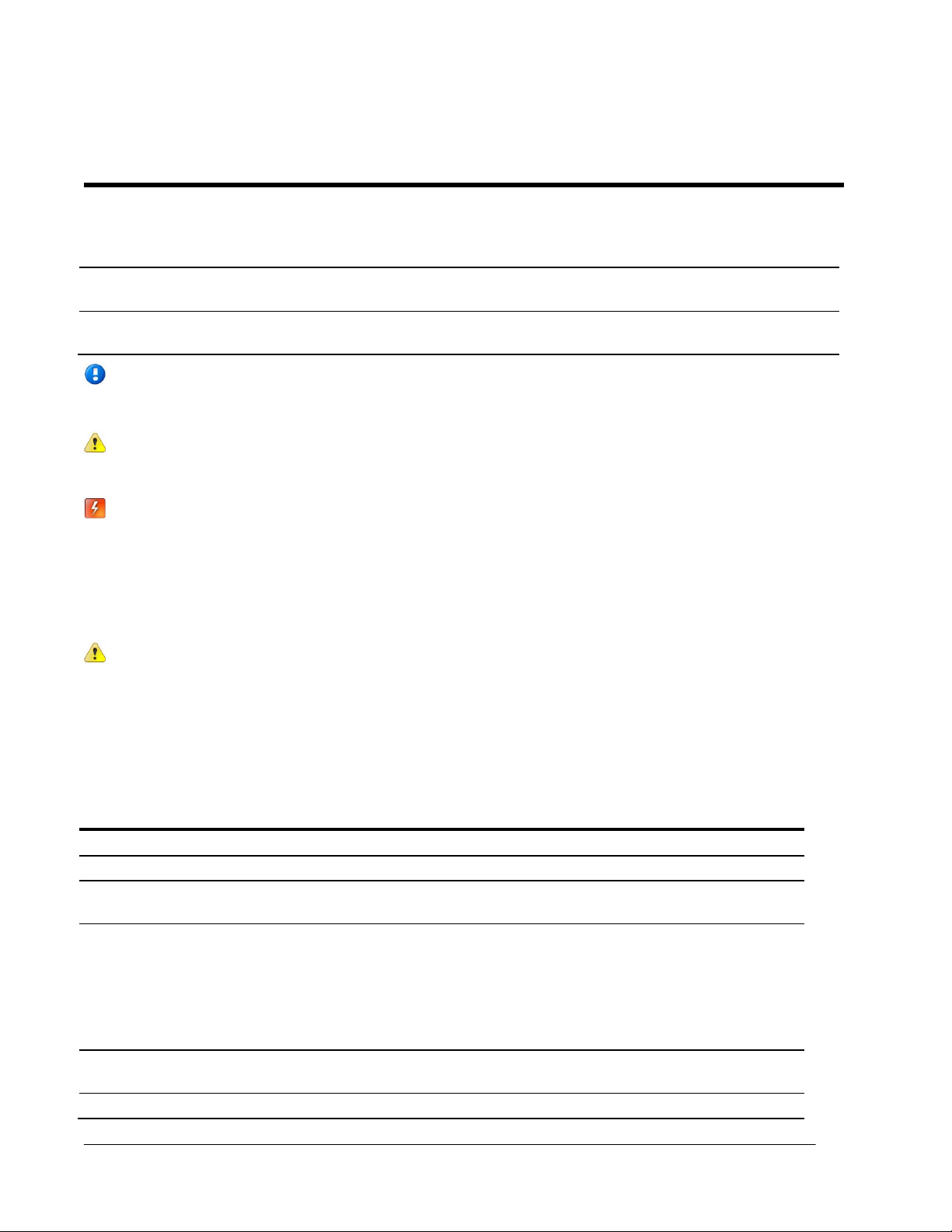
Installing 100W-R and 100WP-R Cable Strain Relief
After you complete the ERT module to register or ERT module to register and Leak Sensor connections (for
more information, see Connecting the Leak Sensor to the 100W-R and 100WP-R ERT Modules), install a
cable tie to the meter cable (and Leak Sensor cable, if applicable) just below the exposed colored lead wires
on the cable insulation. The cable tie performs as a cable strain relief to reduce the risk of destructive tension
on the lead wires.
Page 17
Installing the 100W-R and 100WP-R ERT Modules
TDC-0951-005 100W-R and 100WP-R Datalogging ERT Module Installation Guide 12
Proprietary and Confidential
Required Materials
Remote Mount Kit
CFG-0771-021, single cable port for register connection
CFG-1300-003, dual cable ports for Leak Sensor and register connection
Sidecutter pliers
Gel connector crimping tool
Cable tie gun
Torx T-15 screwdriver
To install the remote ERT module cable strain relief
1. Wrap the cable tie around the meter register or Leak Sensor cable.
2. Insert the pointed end of the cable tie into the receptacle end of the cable tie with the ribbed edge facing
in.
Page 18
Installing the 100W-R and 100WP-R ERT Modules
TDC-0951-005 100W-R and 100WP-R Datalogging ERT Module Installation Guide 13
Proprietary and Confidential
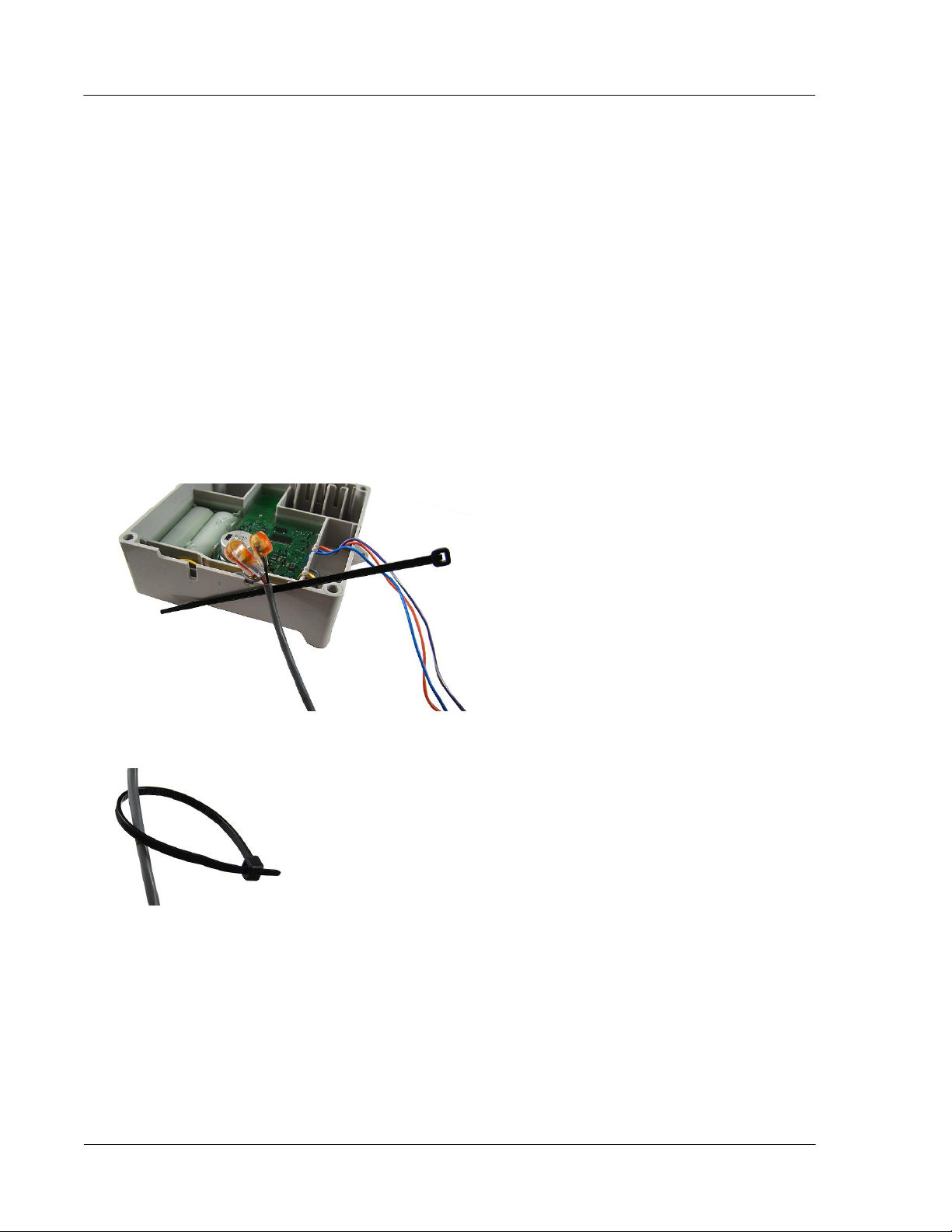
3. Pull the pointed end of the cable tie until hand tight. Insert the excess cable tie into the cable tie gun. Pull
the cable gun trigger to tighten and clip the excess cable tie. The cable tie gun shown is equipped with a
red dial to set the cable tightening pressure of the gun.
Note If your cable tie gun is equipped with a dial to set the tightening pressure, set the pressure to ensure
the cable tie is secure on the lead wire. After installation, the cable tie must not move on the register or
Leak Sensor lead wire.
4. If your cable tie gun does not have a clipping feature, remove the cable tie from the cable tie gun. Using a
sidecutter pliers, remove the excess cable tie.
5. Place the cable connection(s) into the ERT module housing with the cable ties to the inside.
Note The image shown above illustrates the dual cable strain relief for the register and Leak Sensor.
Page 19
Installing the 100W-R and 100WP-R ERT Modules
TDC-0951-005 100W-R and 100WP-R Datalogging ERT Module Installation Guide 14
Proprietary and Confidential
Attaching the Backplate
Select the appropriate remote mount kit for your 100W ERT module (see 100W-R and 100WP-R Accessories
on page 11). Attach the 100W ERT module's backplate before completing a Remote Mount or Pipe Mount
installation.
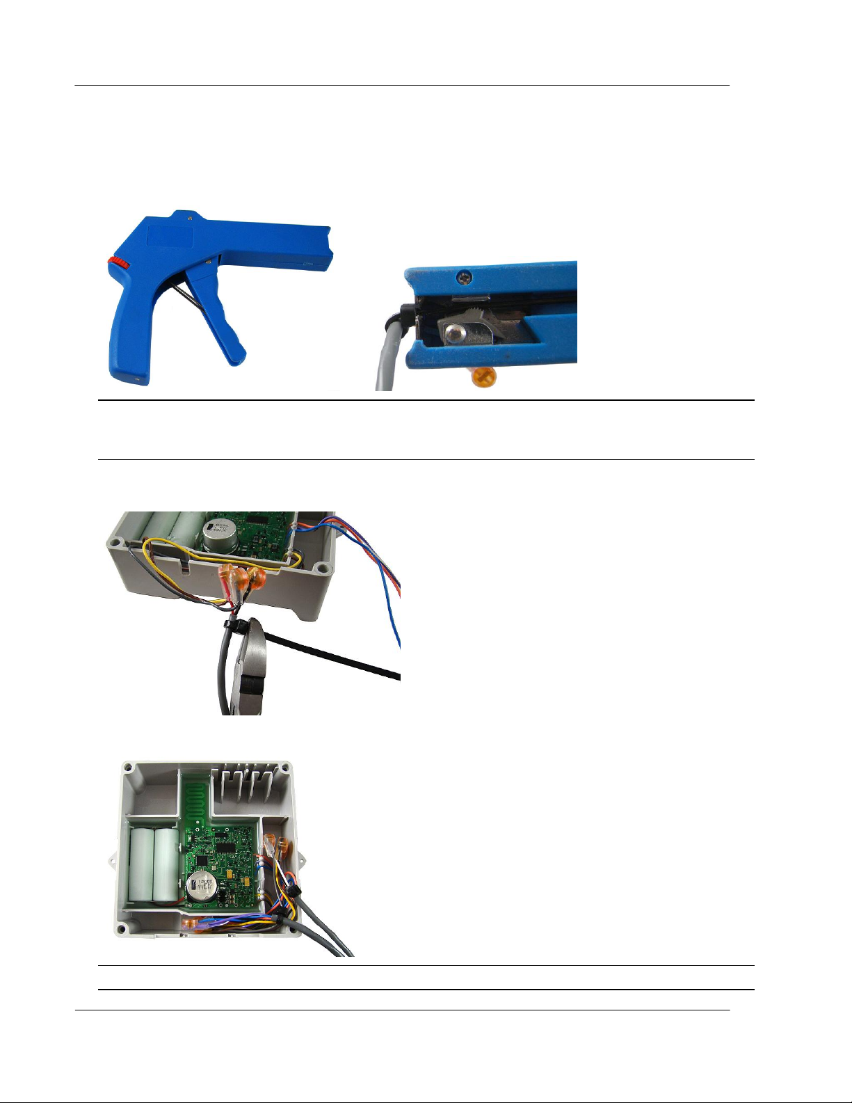
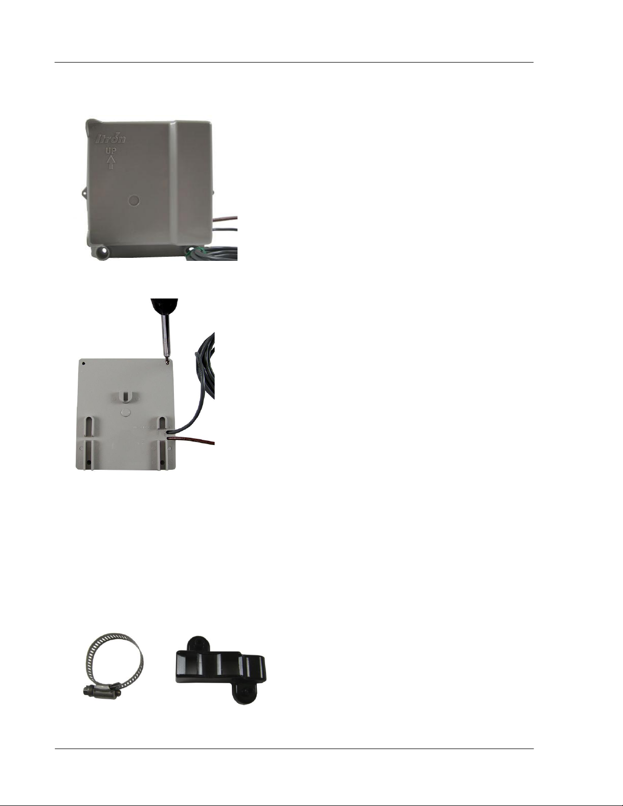
To attach an encoder/pulser only backplate
1. Route the register cable through the single backplate cutout. Ensure the cable strain relief is inside the
module housing and backplate assembly.
2. Align the ERT module backplate with the mounting screw holes. Verify the Itron logo and arrow point up.
Page 20

Installing the 100W-R and 100WP-R ERT Modules
TDC-0951-005 100W-R and 100WP-R Datalogging ERT Module Installation Guide 15
Proprietary and Confidential
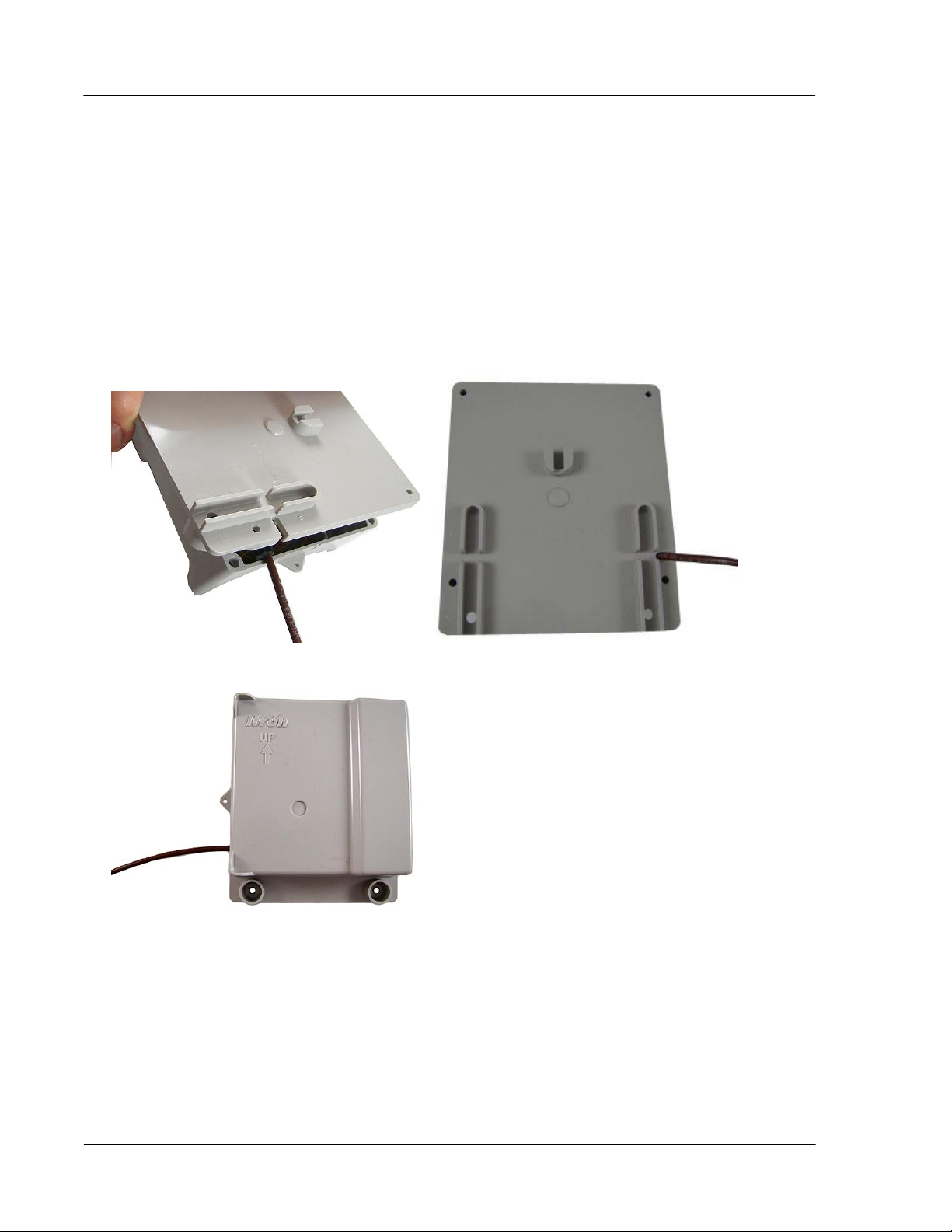
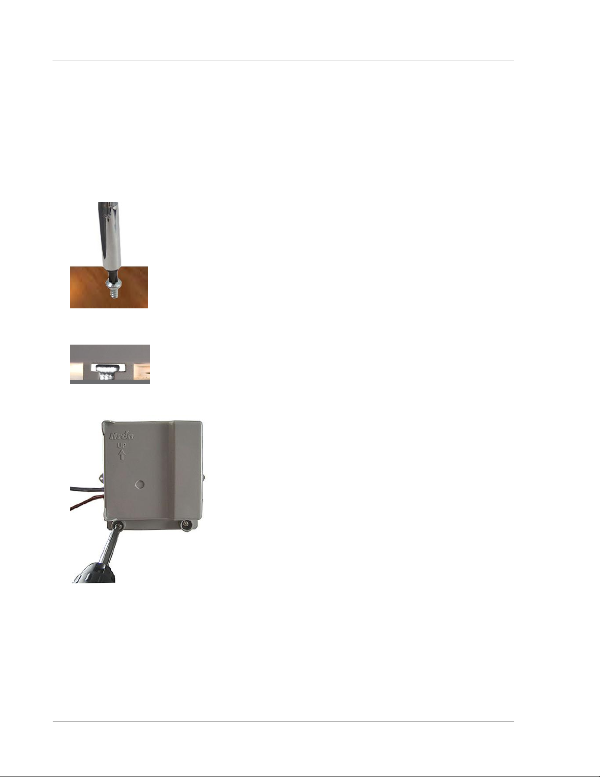
3. Insert a backplate mounting screw in one corner and tighten two to three turns. Insert the remaining three
screws, tightening a few turns.
4. Completely tighten all the screws in an alternating fashion.
To attach an encoder/pulser and leak sensor backplate
1. Route the register cable and Leak Sensor cable through the dual-port backplate. Ensure the cable strain
reliefs are inside the module housing and backplate assembly.
2. Route the register cable through the appropriate backplate cutout and the Leak Sensor cable through the
remaining cutout.
Page 21
Installing the 100W-R and 100WP-R ERT Modules
TDC-0951-005 100W-R and 100WP-R Datalogging ERT Module Installation Guide 16
Proprietary and Confidential
3. Align the ERT module backplate with the mounting screw holes. Verify the Itron logo and arrow point up.
4. Insert a backplate mounting screw in one corner and tighten two to three turns. Insert the remaining three
screws, tightening a few turns.
5. Completely tighten all screws evenly, in an alternating fashion.
Pipe Mount Installation
The ERT module can mount on a pipe vertically, diagonally, or horizontally using a Pipe Mounting Kit and
Remote Mount Kit (see 100W-R and 100WP-R Accessories on page 11).
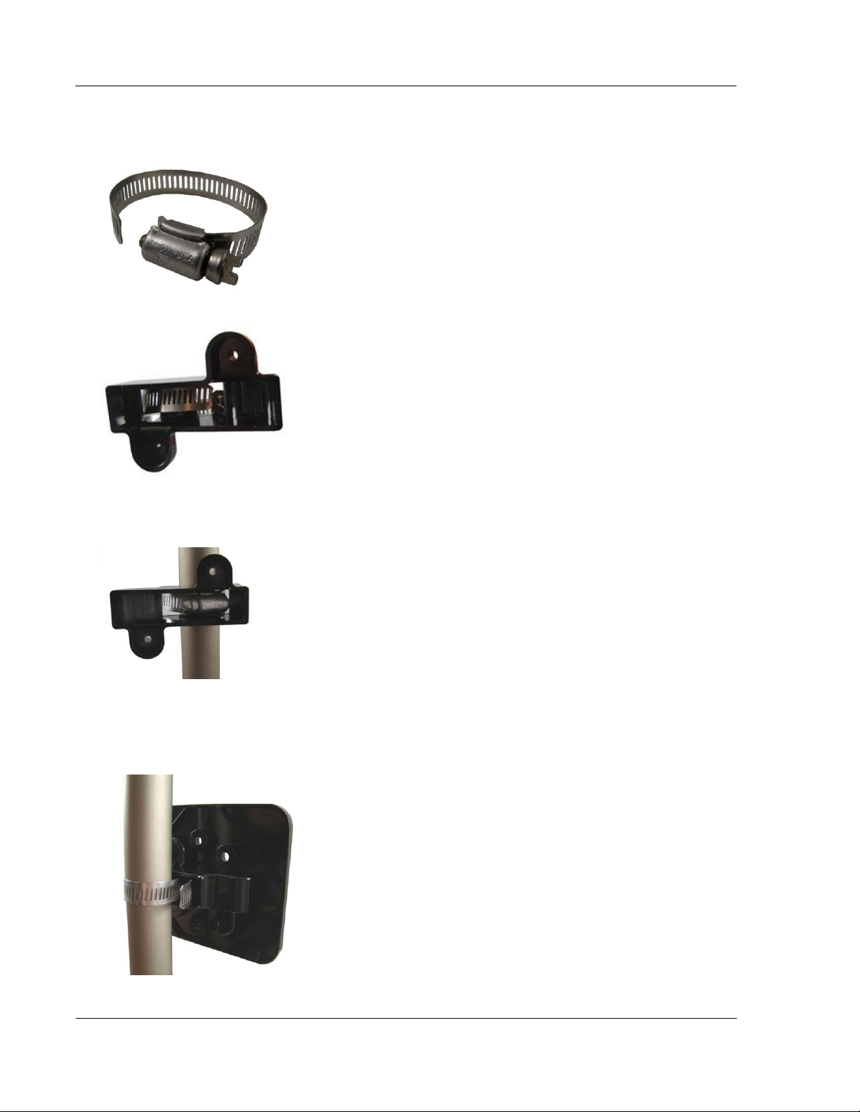
To mount the adapter plate on a vertical pipe
1. Take the pipe bracket and band clamp from the Pipe Mount Kit.
Page 22
Installing the 100W-R and 100WP-R ERT Modules
TDC-0951-005 100W-R and 100WP-R Datalogging ERT Module Installation Guide 17
Proprietary and Confidential
2. Loosen the clamp screw until the end of the band releases.
3. Push the end of the band through the hole in the pipe bracket.
4. Place the band clamp around the pipe. Push the end of the band through the hole in the band clamp and
into the entrance to the screw assembly. Tighten the band clamp until you can push the end of the band
into the hole in the pipe bracket.
5. Tighten the clamp screw three or four more turns to make sure the end of the band does not pop back out
on this side of the pipe bracket. Verify the pipe clamp is in the final installation position on the pipe and
completely tighten the band clamp screw.
6. Place the adapter plate on the pipe bracket. The adapter-plate screw boss goes into the pipe-bracket recess.
Page 23
Installing the 100W-R and 100WP-R ERT Modules
TDC-0951-005 100W-R and 100WP-R Datalogging ERT Module Installation Guide 18
Proprietary and Confidential
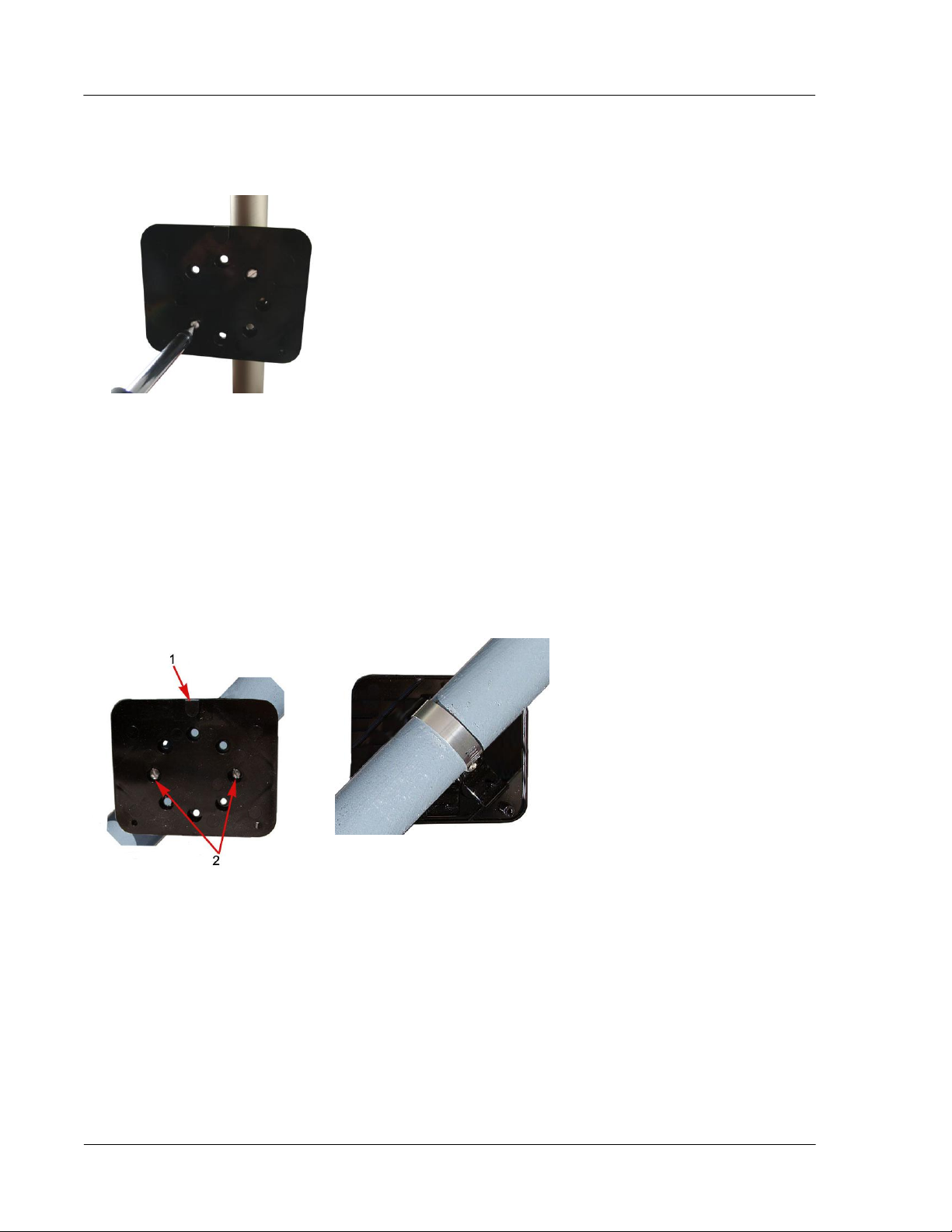
7. Using the two shortest (1/2-inch) adapter-plate mounting screws from the Remote Mount Kit, connect the
adapter plate to the pipe bracket using the screw holes shown below.
8. Tighten both screws to 9 to 12 inch-pounds of torque.
To mount the adapter plate in other positions
The installation procedure in the previous section shows how to mount the adapter plate on a vertical pipe.
The following pictures show the adapter plate on 45 degree angle and horizontal pipes. Regardless of the
angle of the pipe, the adapter plate mounting lug (1) must always be at the top.
If the pipe is at a 45 degree angle up to the right, install the adapter plate with the mounting screws (2) as
shown in the pictures below.
Page 24
Installing the 100W-R and 100WP-R ERT Modules
TDC-0951-005 100W-R and 100WP-R Datalogging ERT Module Installation Guide 19
Proprietary and Confidential
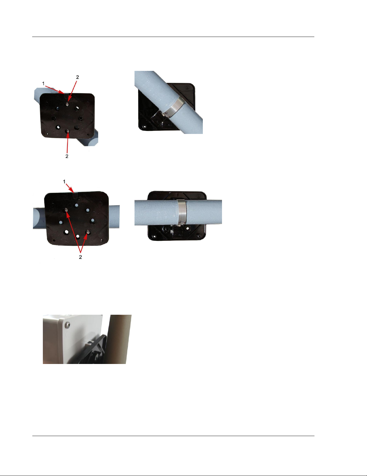
If the pipe is at a 45 degrees angle up to the left, install the adapter plate as shown in the pictures below.
If the pipe is horizontal, install the adapter plate as shown in the pictures below.
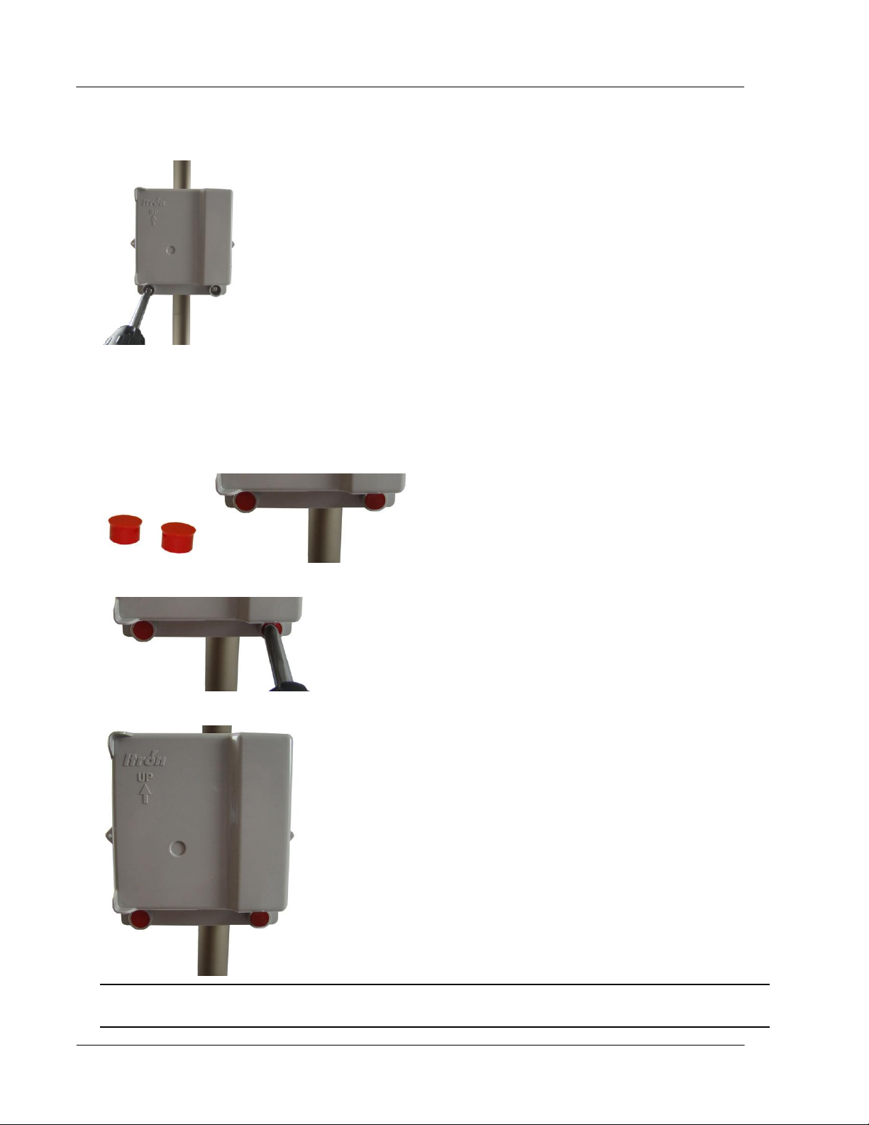
To mount the 100W-R and 100WP-R ERT modules on the adapter plate
1. Locate the two 1-inch ERT module mounting screws in the Pipe Mount Kit.
2. Slide the ERT module back cover onto the adapter, pushing up to secure the lug adapter in the lug slot.
Page 25
Installing the 100W-R and 100WP-R ERT Modules
TDC-0951-005 100W-R and 100WP-R Datalogging ERT Module Installation Guide 20
Proprietary and Confidential
3. Install the two 1-inch ERT module mounting screws.
4. Tighten the screws to 9 to 12 inch-pounds of torque.
To install tamper seals and cable ties
1. Using the two new tamper seals from the mounting kit, place a new tamper seal over each ERT module
mounting screw.
2. Push both tamper seals all the way into place with a 1/4-inch nut driver or similar tool.
The final installation will resemble the image below after the tamper seals are installed.
Note A tamper seal is fully seated when the top of the tamper seal is approximately 1/16-inch below the
top of the screw recess.
Page 26
Installing the 100W-R and 100WP-R ERT Modules
TDC-0951-005 100W-R and 100WP-R Datalogging ERT Module Installation Guide 21
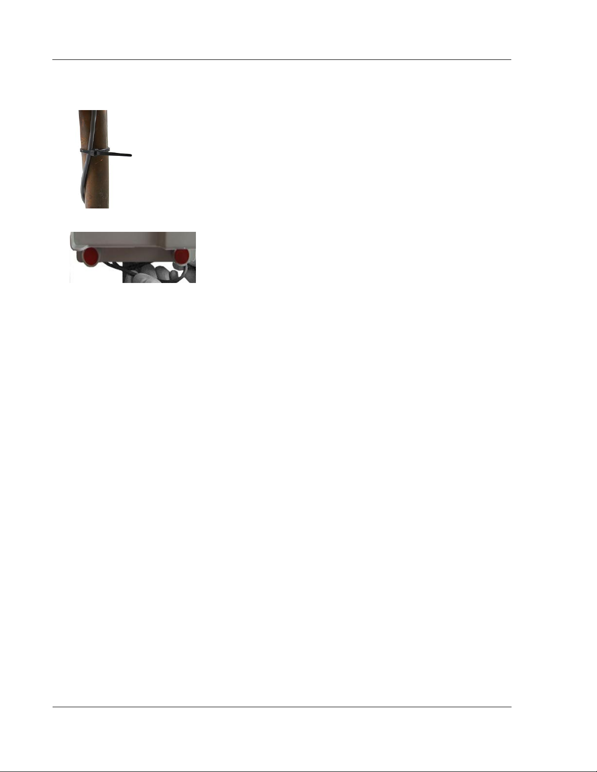
Proprietary and Confidential
3. Secure the cable to the meter pipe with a cable tie.
4. Push excess wire up between the back of the ERT module and the face of the adapter plate.
Optional Leak Sensor Installation
Leak Sensors (LS) analyze water flow sound patterns to detect new, evolving, and pre-existing leaks. LS
analysis data is uploaded to mlogonline™ Network Leak Monitoring for data analysis and accessed through a
secure Internet portal unique to your utility. This section describes installation of the Leak Sensor (LS) in a
100W-R and 100WP-R ERT modules system.
The ERT module stores 20 days of Leak Sensor data. On the 21st day, the ERT module begins to write over
stored data in a first in, first out manner.
The ERT module automatically detects the presence of connected Leak Sensors. The ERT module will
automatically detect the Leak Sensor within 22.5 minutes and begin reading Leak Sensor data. To
immediately detect the Leak Sensor and begin reading data, perform a Check ERT with a handheld computer
running FDM software.
The LS is used in conjunction with both indoor (basement) and outdoor (mounting on the exterior of the
house) 100W-R and 100WP-R ERT modules installations. LS devices are mounted on a water service pipe or
meter insetter (meter horn) and connect to the Leak Sensor connector on the ERT module as described in
Connecting the Leak Sensor to the 100W-R and 100WP-R ERT Modules on page 22. The mounting bracket
shipped with the Leak Sensor accommodates an (up to) 1-1/2-inch OD pipe. An optional mounting bracket is
available for pipe sizes (up to 2 1/2-inch OD).
Page 27
Installing the 100W-R and 100WP-R ERT Modules
TDC-0951-005 100W-R and 100WP-R Datalogging ERT Module Installation Guide 22
Proprietary and Confidential
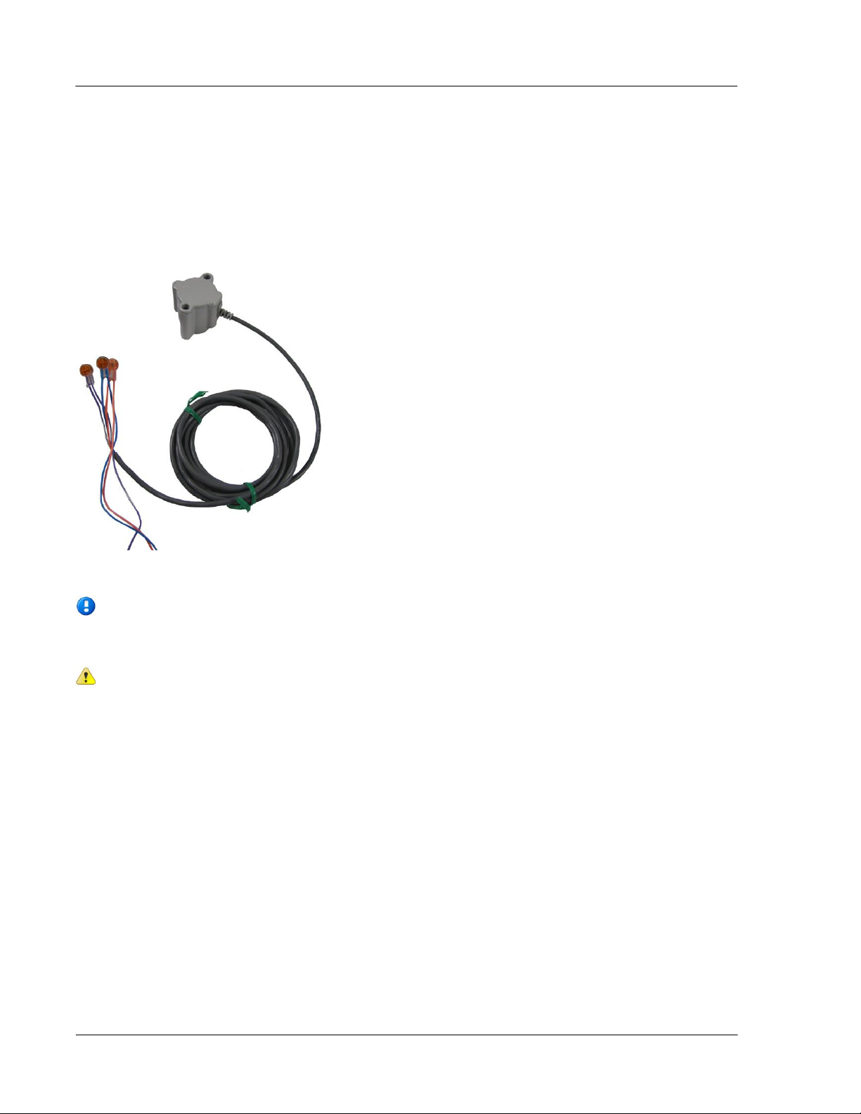
Connecting the Leak Sensor to the 100W-R and 100WP-R ERT Modules
Note If the ERT module will mount on the exterior of the house but the Leak Sensor is on a
pipe on the interior, the Leak Sensor cable must run through a hole in the wall before connecting
it to the ERT module.
Caution Extension cable lengths must not exceed 300 ft. Extension cabling from Itron is
stranded, tinned, and pre-bonded for reliability and proper connection to gel cap connectors.
Extension cabling manufactured by non-approved Itron manufacturers may result in unreliable
and problematic connections. Contact Itron Support for more information.
Connecting a Leak Sensor to the 100W-R and 100WP-R ERT modules requires a Leak Sensor enabled ERT
module. See 100W-R and 100WP-R Models on page 4. Connect the ERT modules flying lead wires to the
Leak Sensor (using gel cap connectors, see Using Gel Cap Connectors on page 37) matching wire colors to
complete the three connections.
See Optional Leak Sensor Installation on page 21 for Leak Sensor mounting information.
Page 28

Installing the 100W-R and 100WP-R ERT Modules
TDC-0951-005 100W-R and 100WP-R Datalogging ERT Module Installation Guide 23
Proprietary and Confidential
Equipment
Itron Part Number
Description
Leak Detection Sensor
LDS-0001-001
LDS with bracket; 5-foot cable, and mounting bolt (fits up to 1-1/2inch OD pipe).
Optional mounting bracket
CFG-0349-002
Mounting bolt fits up to 2-1/2-inch OD pipe.
100W-R Encoder Remote
ERW-1300-214
100W-R with Leak Sensor, 10-inch flying lead.
100WP-R Pulser Remote
ERW-1300-216
100WP-R with Leak Sensor, 10-inch flying lead.
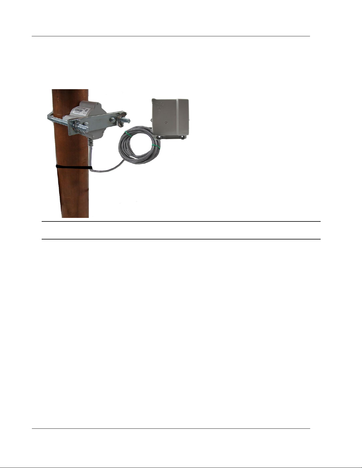
Required Equipment
Leak Sensor Standard mounting 100W remote ERT module Optional mounting
bracket bracket
Pipe Preparation
Clean any dust or dirt from the pipe to facilitate direct contact with the LS surface.
To install the Leak Sensor on a pipe or meter insetter
1. Select a Leak Sensor mounting location. Mount the sensor on the water input side of the meter.
Caution The Leak Sensor must be mounted on the water input side of the meter. Failure to follow this
mounting requirement could result in errors in the leak detection data. Installation requires Itron mounting
hardware. Repair costs and service charges relating to the use on non-compliant mounting hardware will
be charged to the customer. Contract Itron Support for more information.
Page 29

Installing the 100W-R and 100WP-R ERT Modules
TDC-0951-005 100W-R and 100WP-R Datalogging ERT Module Installation Guide 24
Proprietary and Confidential
2. Verify the pipe’s mounting surface is free from dirt and debris. Place the curved surface of the LS against
the pipe.
3. Insert the mounting U-bolt over the pipe and into the LS mounting holes.
Caution Do not mount the Leak Sensor on a pipe coupler, joint, or nut.
Page 30

Installing the 100W-R and 100WP-R ERT Modules
TDC-0951-005 100W-R and 100WP-R Datalogging ERT Module Installation Guide 25
Proprietary and Confidential
4. Insert the mounting plate over the U-bolt's threaded screw ends. Attach the two wing nuts over the clamp
screw ends and tighten the wing nuts until snug (to a minimum of 5-inch pounds) to prevent device
rotation on the pipe. After the second wing nut is tightened, check the Leak Sensor to verify the device is
snug. If the sensor moves, tighten the wing nuts until there is no movement.
Caution Do not tighten the Leak Sensor to more than 20 inch-pounds. Over-tightening could damage the
Leak Sensor housing and/or the pipe.
Note Leak Sensor mounting orientation is not critical. Orient the sensor to best accommodate your
installation. The most important installation practice is to mount the sensor securely to the pipe.
To install the Leak Sensor on a pipe (up to 2 1/2-inch OD)
1. Select a Leak Sensor mounting location within 5-feet of the 100W ERT module.
Note Leak Sensor mounting orientation is not critical. Orient the Sensor to best accommodate your
installation. The most important installation practice is to fasten the Sensor securely to the pipe.
Caution The Leak Sensor must be mounted on the water input side of the meter. Failure to follow this
mounting requirement could result in errors in the leak detection data. Installation requires Itron mounting
hardware. Repair costs and service charges relating to the use on non-compliant mounting hardware will
be charged to the customer. Contract Itron Support for more information.
Page 31

Installing the 100W-R and 100WP-R ERT Modules
TDC-0951-005 100W-R and 100WP-R Datalogging ERT Module Installation Guide 26
Proprietary and Confidential
2. Insert the mounting plate screws into the holes on the Leak Sensor's curved surface.
3. Secure the mounting plate to the Leak Sensor.
4. Verify the pipe’s mounting surface is free from dirt and debris. Place the curved surface of the LS against
the pipe.
Caution Do not mount the Leak Sensor on a pipe coupler, joint, or nut.
Page 32
Installing the 100W-R and 100WP-R ERT Modules
TDC-0951-005 100W-R and 100WP-R Datalogging ERT Module Installation Guide 27
Proprietary and Confidential
5. Insert the U-bolt around the pipe and into the holes in the plate/Leak Sensor assembly. Secure the U-bolt
with the wing nuts. Tighten the wing nuts until snug (to a minimum of 5-inch pounds) to prevent device
rotation on the pipe. After the second wing nut is tightened, check the Leak Sensor to verify the device is
snug. If the sensor moves, tighten the wing nuts until there is no movement.
Caution Do not tighten the Leak Sensor to more than 20 inch-pounds. Over-tightening could damage the
Leak Sensor housing and/or the pipe.
Remote Mount Installation
Connect the ERT module to the register as described in Connecting, Initializing, and Programming the ERT
Module on page 7.
Using a back plate, create a template by drilling through a back plate lug slot to mark the position of the
screw. Use the drilled back plate as your mounting template.
The arrow on the ERT module must point up when installation is complete.
Required Tools and Hardware
Remote mount installation requires the following tools and hardware:
Remote Mount Kit (CFG-0771-021 or CFG-1300-003) includes the back plate, tamper seals, and
mounting screws
Nut driver or similar tool
Phillips screwdriver
Drill and bits for mounting surface and screw size
Page 33
Installing the 100W-R and 100WP-R ERT Modules
TDC-0951-005 100W-R and 100WP-R Datalogging ERT Module Installation Guide 28
Proprietary and Confidential
To install on a flat surface
1. Select an installation location.
2. Using a back plate template, drill three pilot holes into the wall or other surface. The two bottom holes
should be level.
3. Screw a mounting screw for the lug slot into the surface, leaving approximately 1/8-inch of the screw
protruding. The lug slot should slide over the screw with a tight fit.
4. Slide the ERT lug slot onto the mounting screw, pushing the ERT module upward until the screw head is
all the way into the slot.
5. Screw the ERT module to the wall using the remaining two mounting screws.
Page 34

Installing the 100W-R and 100WP-R ERT Modules
TDC-0951-005 100W-R and 100WP-R Datalogging ERT Module Installation Guide 29
Proprietary and Confidential
6. Insert a tamper seal over each mounting screw and drive into place with a nut driver or a similar tool.
Note If you are installing an ERT module with Leak Sensor capability, use a needle-nose pliers to
remove one of the ERT module's housing knock-outs to accommodate the Leak Sensor cable. If
your meter register has a raised internal rim, remove the larger case knock-out. When you are
installing a Leak Sensor with the 100W-R or 100WP-R, you must install cable strain relief prior to
installing the ERT module. For more information, see Installing 100W-R and 100WP-R Cable
Strain Relief on page 11.
Warning Do not use the direct mounting method in a pit environment. Use a pit ERT module for pit
environments. 100W-R and 100WP-R ERT modules direct mounted in a pit environment are not
covered by the Itron warranty.
Note A tamper seal is fully seated when the top of the tamper seal is approximately 1/16 inch below the
top of the screw recess.
7. Secure any excess cable using the provided cable ties.
Direct-Mounting to the Meter Register
Direct mounting ERT modules to a meter register requires a register designed for that purpose. This section
describes 100W-R and 100WP-R installation for the following direct mount registers:
Badger ADE and RTR
Elster/AMCO (ABB) Scancoder, InVISION, and Digital
Page 35
Installing the 100W-R and 100WP-R ERT Modules
TDC-0951-005 100W-R and 100WP-R Datalogging ERT Module Installation Guide 30
Proprietary and Confidential
To install the 100W-R and 100WP-R ERT modules to a Badger Direct-Mount register
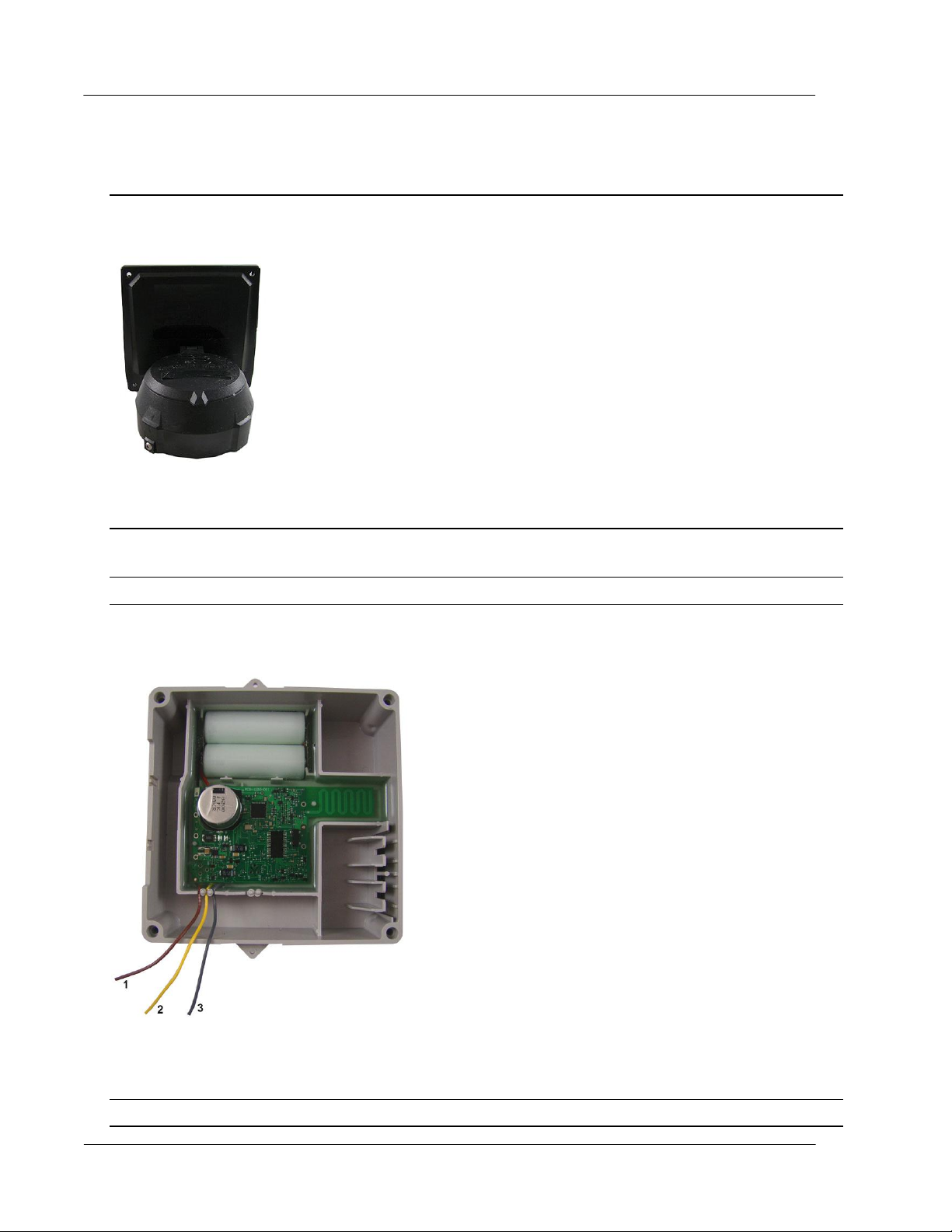
(1)
brown insulated wire
(2)
yellow insulated wire
(3)
gray insulated wire
Caution
Verify you have a Badger meter with a register designed for direct mount ERT modules.
Check the part number on the label to verify the module matches the meter.
Always install the module with the arrow on the housing pointing upward.
Note The register may or may not be mounted on the meter when performing the following steps.
1. Direct-meter mounting requires a 100W-R ERT module for the Badger ADE register or a 100WP-R for
the RTR register. Both ERTs have three wires:
Note For an RTR register, tuck the unused yellow wire into the housing.
Page 36
Installing the 100W-R and 100WP-R ERT Modules
TDC-0951-005 100W-R and 100WP-R Datalogging ERT Module Installation Guide 31
Proprietary and Confidential
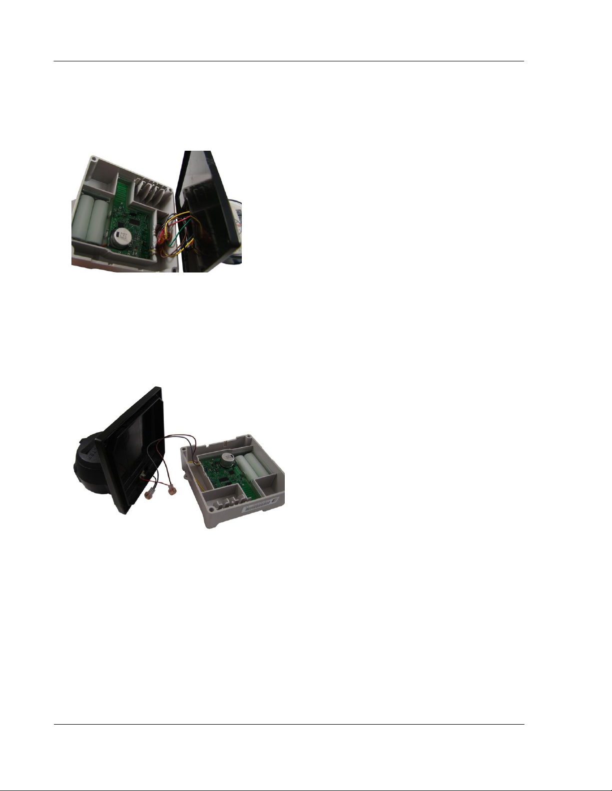
2. Connect the ERT module wires to the register using gel-cap connectors (see Using Gel-cap Connectors on
page 37) following the 100W-R encoder to the Badger ADE register wire connections, (see Connecting
100W-R to a Remote Meter Register on page 8). After connecting the wires, carefully tuck the connectors
into the ERT module housing.
3. To wire the 100WP-R to the RTR 2-wire register, connect the ERT module wires to the 2-wire register
using gel-cap connectors (see Using Gel-cap Connectors on page 37). After connecting the wires,
carefully tuck the connectors into the ERT module housing.
4. To connect the 100WP-R pulser to the RTR 2-wire register, see Connecting the 100WP-R to a Remote
Meter Register on page 9. The ERT module's yellow wire is not used. Tuck the yellow wire back into the
ERT module housing with the gel-cap connectors.
Page 37
Installing the 100W-R and 100WP-R ERT Modules
TDC-0951-005 100W-R and 100WP-R Datalogging ERT Module Installation Guide 32
Proprietary and Confidential
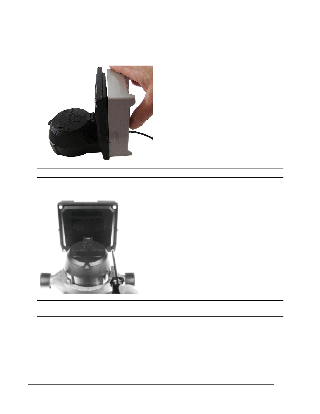
5. Place the ERT module on the register, ensuring the edge of the ERT module housing is seated properly
around the perimeter of the register as shown below.
Note A gasket is not required.
6. Install four Torx-head mounting screws (SCR-0010-005) as shown below and hand-tighten the screws.
Warning User Itron mounting screws (SCR-0010-005). Using the wrong mounting screws could crack
the plastic ERT module housing.
Page 38
Installing the 100W-R and 100WP-R ERT Modules
TDC-0951-005 100W-R and 100WP-R Datalogging ERT Module Installation Guide 33
Proprietary and Confidential
7. If you have not already done so, connect the register to the water meter and fully tighten the mounting
screw (1) as directed by Badger Meter.
Note Mount the register on the meter in one of four different positions with respect to the direction of
water flow (refer to the manufacturer's installation directions).
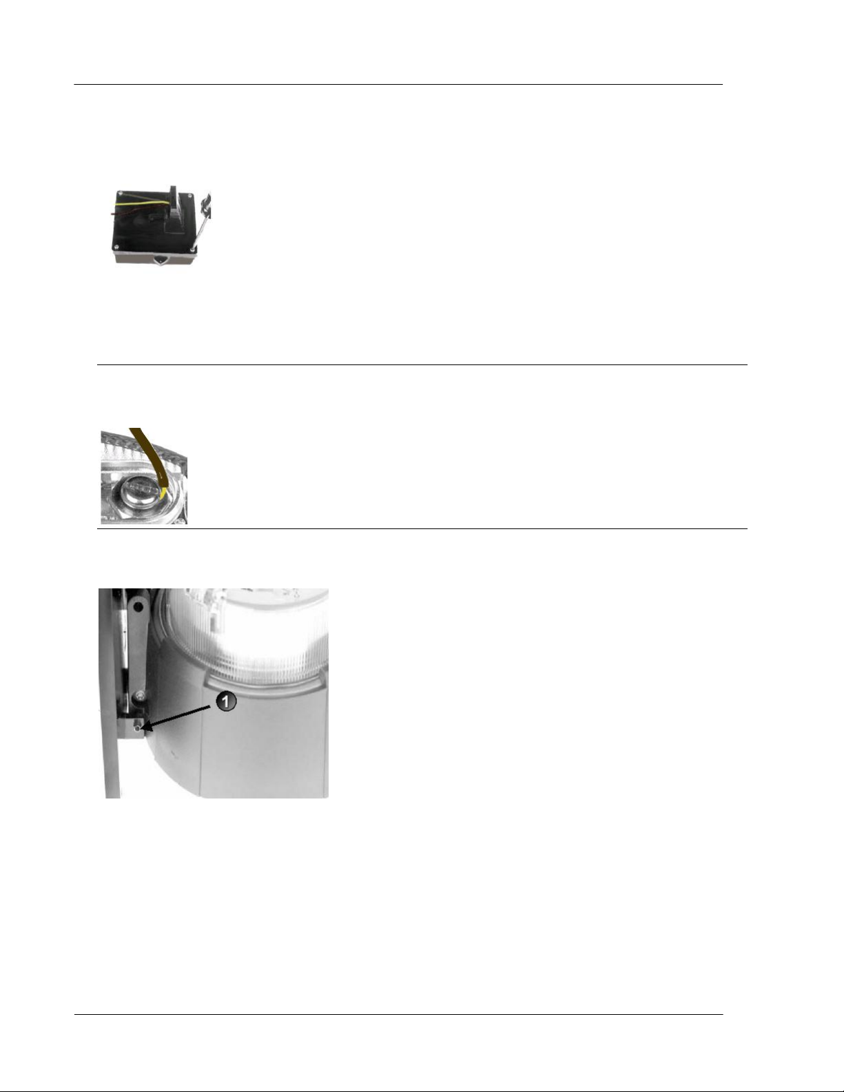
8. If the standard Torx screw is used (1), a wire seal is not necessary.
If the optional slotted and drilled RTR screw is used, install a wire seal through the drilled screw from (1)
to (2), or as specified by utility policy.
Page 39
Installing the 100W-R and 100WP-R ERT Modules
TDC-0951-005 100W-R and 100WP-R Datalogging ERT Module Installation Guide 34
Proprietary and Confidential
To install the Elster/AMCO (ABB) Scancoder, InVISION, or Digital Direct-Mount
Caution
Verify you have an Elster/AMCO meter with a register designed for direct mount ERT modules.
Always install the ERT module right side up with the arrow on the housing pointed upward.
Note The register may or may not be mounted on the meter when performing the following steps.
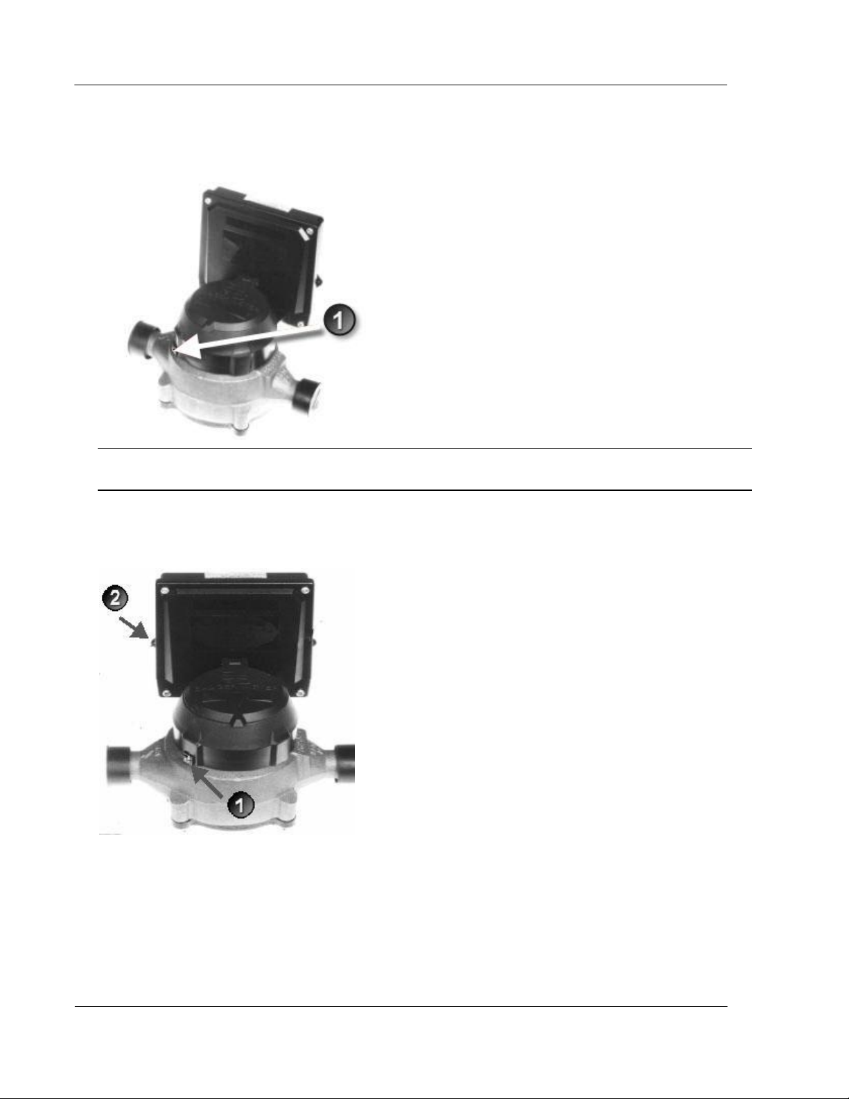
1. Push the hollow pin (1) completely out of its location and separate the ERT module mounting bracket (2)
from the meter register collar (3).
Page 40
Installing the 100W-R and 100WP-R ERT Modules
TDC-0951-005 100W-R and 100WP-R Datalogging ERT Module Installation Guide 35
Proprietary and Confidential
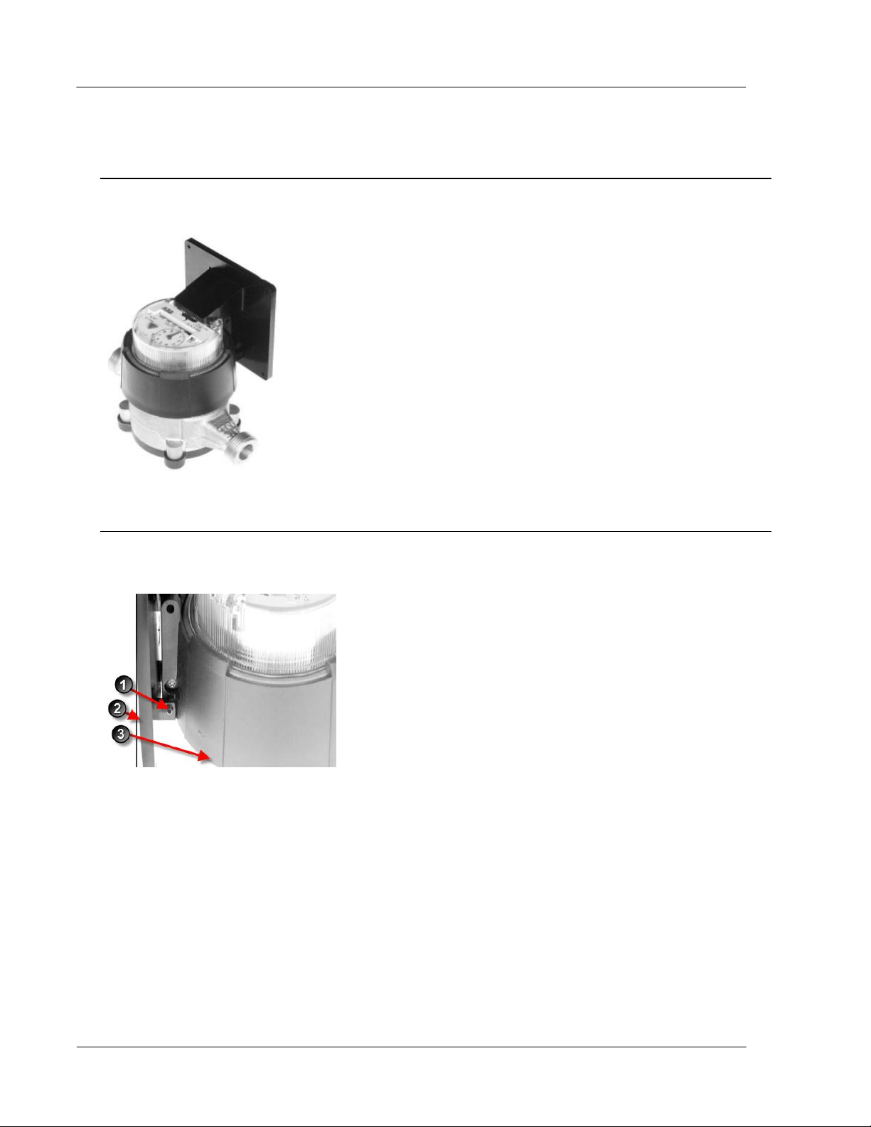
2. Installation requires a 100W-R ERT module for an InVISION or Scancoder register. Installation for a
Digital register requires a 100WP-R.
3. Strip 1/2-inch of insulation from the end of the brown, gray, and yellow wires.
4. Place the ERT module on the mounting bracket and route the yellow, gray, and brown wires through the
opening.
Note A gasket is not required.
Page 41
Installing the 100W-R and 100WP-R ERT Modules
TDC-0951-005 100W-R and 100WP-R Datalogging ERT Module Installation Guide 36
Proprietary and Confidential
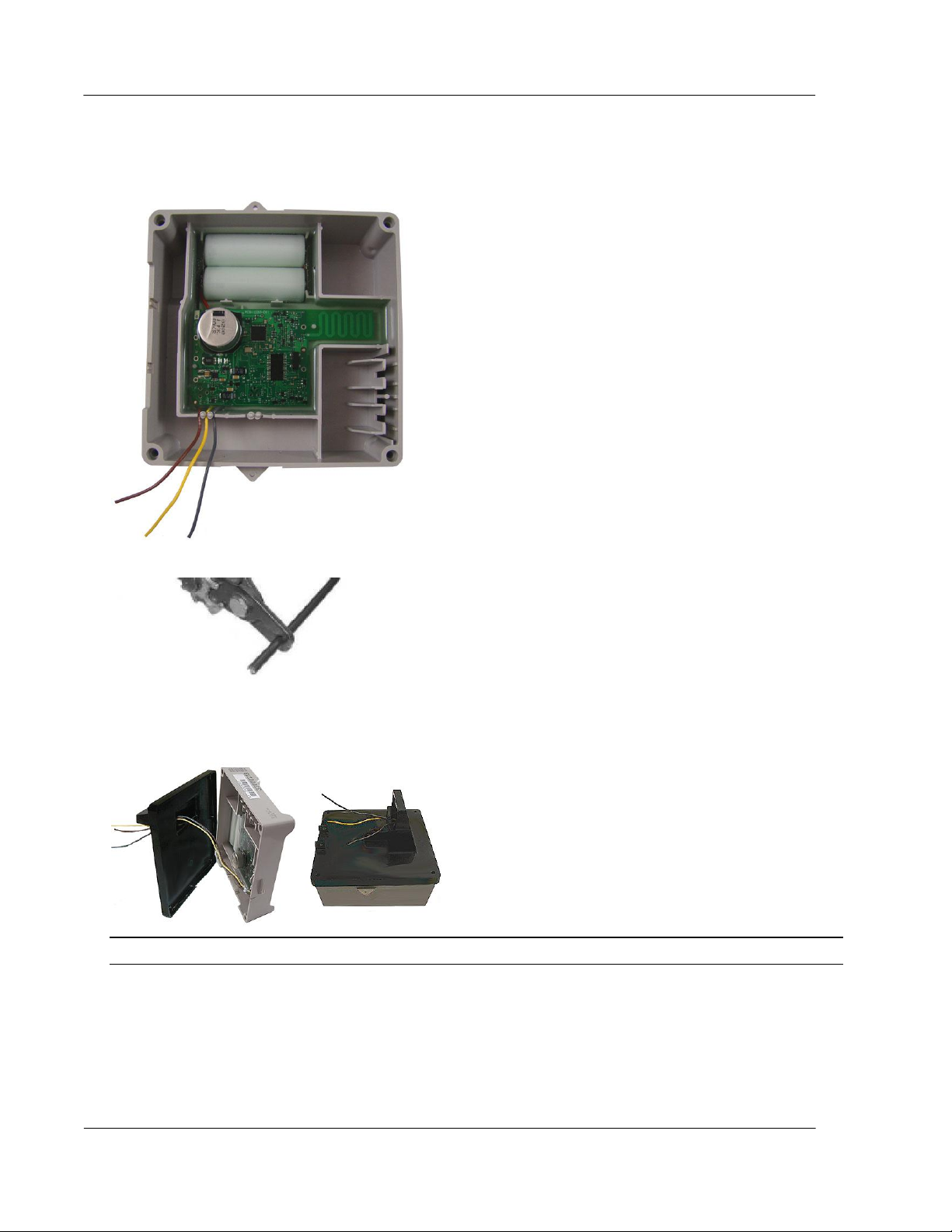
5. Install four Torx-head mounting screws (Itron Part Number SCR-0010-005) as shown below. Hand
tighten each screw.
6. Connect the ERT module wires to the register screw terminals following the 100WP-R pulser to the
Elster/AMCO meter register wire connections, (see Connecting 100WP-R to a Remote Meter Register on
page 9). After connecting the wires, carefully tuck the connectors into the ERT module housing. Tighten
all screws securely.
Caution Install the wires around the screws in a clockwise direction (as shown) or the wires may come
out from under the screw heads as you tighten them. Also, verify insulation is NOT compressed under the
screw head, or the wire may not make good contact.
7. Install the module and mounting bracket on the meter register adapter collar.
8. Replace the hollow pin (1) you removed in step 1.
Page 42

TDC-0951-005 100W-R and 100WP-R Datalogging ERT Module Installation Guide 37
Proprietary and Confidential
This section describes connecting the 100W-R and 100WP-R ERT modules to the water meter register using
A P P E N D I X A
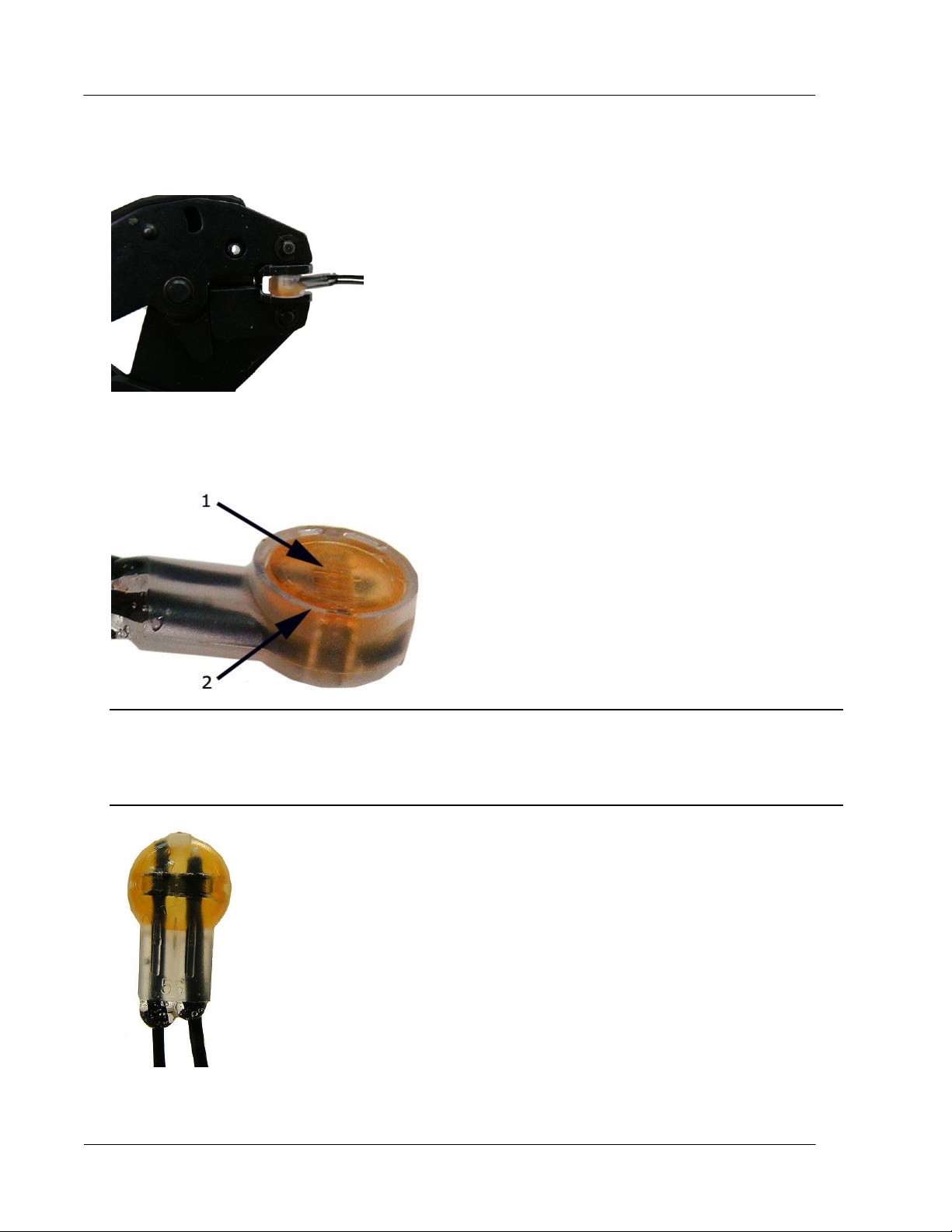
Using Gel-cap Connectors
gel cap connectors.
Required Materials
E-9R 3M® gel cap crimping tool
Gel cap connectors
1. Push two wires as far as possible into the connector.
Caution Do not strip insulation from the ends of the wires before inserting them into the connector.
2. Carefully place the connector and wires into the jaws of the crimping tool. Make sure the wires remain
fully inserted in the gel-cap connector.
Page 43
Using Gel-cap Connectors
TDC-0951-005 100W-R and 100WP-R Datalogging ERT Module Installation Guide 38
Proprietary and Confidential
3. Crimp the connector by squeezing the handles until the connector cap is fully seated. Continue to apply
pressure for three seconds.
4. A connector is crimped properly when the top of the movable yellow center (1) is flush with the top of the
connector body (2).
Warning Crimping the connector forces some sealant out of connector. The sealant protects the inside of
the connector against insects, moisture, and other contaminants.
The sealant may cause minor eye and skin irritation. Avoid eye contact. Avoid prolonged or repeated skin
contact. Contact Itron Support for Material Safety Data Sheets (MSDS).
Page 44

TDC-0951-005 100W-R and 100WP-R Datalogging ERT Module Installation Guide 39
Proprietary and Confidential
This chapter provides the information to help you troubleshoot issues related to the 100W-R and 100WP-R
Issue
Action
Cannot program the ERT module.
Check the programming device and software version. Program ERT modules using the
FC300 handheld computer running Field Deployment Manager (FDM) software.
Cannot read the ERT module.
An ERT module that is not programmed will not transmit an SCM. Reprogram the ERT
module and perform a reread. If an ERT module is not initially programmed, it will not
bubble-up and listen for an SCM.
The encoder ERT module is reporting an
invalid read.
An encoder ERT module that has set the Last Good Read flag will cause an Invalid
Read to display in the FDM Consumption field.
Marginal readability due to water ERT module
location (for example, an ERT module deep
inside a pit).
Consider reprogramming the ERT module for Hard-to-Read (H2R) mode. This
increases the output power to Fixed Network levels.
Note This mode will reduce battery life.
The ERT module in a Fixed Network is not
reporting.
Perform a Check ERT and verify the ERT module is in FN mode. If the CCU's pathway
is obstructed, consider including an 8-channel repeater. Systems that utilize Fixed
Network v4.0 software and a CCU100 may require a Repeater 100.
The handheld programmer is locked up and
button presses produce no response.
Soft boot the handheld by pressing and holding buttons A and B until the screen fades.
Release the buttons and allow the handheld to reboot.
A P P E N D I X B
Troubleshooting
ERT moduless.
The following table describes possible issues and provides suggested actions to resolve the issue.
Page 45

TDC-0951-005 100W-R and 100WP-R Datalogging ERT Module Installation Guide 40
Proprietary and Confidential
Symbols & Numbers
Index
100WP-R Operating Modes • i
100WP-R Pulser Start-up • i
100W-R and 100WP-R ERT Module Accessories
• i, i, i
100W-R and 100WP-R Models • i, i, i
100W-R and 100WP-R Transmission Modes • i
100W-R Encoder Start-up • i
100W-R Operating Modes • i
A
About the 100W-R and 100WP-R • i
Attaching the Backplate • i
B
Battery Life • i
Before You Begin • i
C
Connecting the 100WP-R to a Remote Meter
Register • i, i, i
Connecting the 100W-R to a Remote Meter
Register • i, i
Connecting the Leak Sensor to the 100W-R and
100WP-R ERT Modules • i, i
D
Direct-Mounting to the Meter Register • i, i
H
How This Document is Organized • i
Installing 100W-R and 100WP-R Cable Strain
Relief • i, i
Installing the 100W-R and 100WP-R ERT
Modules • i
O
Optional Leak Sensor Installation • i, i
P
Pipe Mount Installation • i, i
Pipe Preparation • i
Programming and Connecting the 100W-R and
100WP-R • i, i, i
Programming the 100WP-R • i
R
Related Documents • i, i
Remote Mount Installation • i, i
Required Equipment • i
Required Tools and Hardware • i
T
Troubleshooting • i
U
Using Gel-cap Connectors • i, i, i, i
V
Verifying 100W-R and 100WP-R ERT Module
Operation • i
I
Initializing the 100W-R • i
 Loading...