

Page 1

The WindowWasher™ by ITR
Installation and
Operating Manual
Diesel Fired Continuous Output
Window Cleaning Water Heater
Page 2

Copyright © February 2012
International Thermal Research
IN CANADA: IN THE UNITED STATES:
2431 Simpson Road 11915 NE 56
Richmond, BC, Canada V6X 2R2 Vancouver, WA, USA 98682
Tel: 1-800-755-1272 or 604-278-1272 Tel: 1-800-993-4402 or 360-993-4877
Fax: 604-278-1274 Fax: 360-993-1105
Email: info@itrheat.com Email: info@itrheat.com
th
Circle, Suite B
Website: http://www.itrheat.com
All rights reserved. No part of this manual may be reproduced or
transmitted in any form by any means, electronic or mechanical,
including photocopying and recording, information storage,
retrieval, or transmission, without permission in writing from
International Thermal Research
Right to Modify:
Due to our commitment for quality and ongoing product
improvement, ITR reserves the right to modify or change
without notice, any materials, applications, equipment,
accessories, and/or prices. All measurements and weights are
approximate.
Page 3

Table of Contents
Table of Contents
Section 1, Overview .................................................. 1-1
1.1 Unpacking The WindowWasher™ by ITR ........... 1-2
1.2 Protect Your Warranty ................................... 1-2
1.3 The WindowWasher™ by ITR Features ............. 1-3
1.4 Critical Factors ............................................. 1-4
1.5 Equipment, Tools and Skills ............................ 1-4
1.6 Testing and Inspection .................................. 1-5
Section 2, Mounting - The WindowWasher™ ............ 2-1
2.1 Before You Begin .......................................... 2-1
2.2 Your Mounting Location ................................. 2-2
2.3 Procedure .................................................... 2-4
Section 3, Installing the Exhaust System .................. 3-1
3.1 Before You Begin .......................................... 3-1
3.2 Mounting Location ........................................ 3-1
Recommended Exhaust Outlet Locations ............ 3-1
Recommendation for Installation ...................... 3-2
What NOT to Do ............................................. 3-4
3.3 Procedure .................................................... 3-4
Section 4, Installing the Fuel System ........................ 4-1
4.1 Before You Begin .......................................... 4-1
4.2 Fuel System Operation .................................. 4-1
Recommendation for Installation ...................... 4-1
4.3 What NOT to Do ........................................... 4-2
4.4 Procedure .................................................... 4-3
Section 5, Wiring the Electrical System ..................... 5-1
5.1 Before You Begin .......................................... 5-1
5.2 12 VDC ....................................................... 5-1
5.3 Remote Operating Panel Cable ........................ 5-2
5.4 Main Electronic Control Board ......................... 5-2
5.5 What NOT to Do ........................................... 5-3
iv WindowWasher by ITR Installation Manual
Page 4

Table of Contents
Section 6, Plumbing the System ................................ 6-1
6.1 Before You Begin ......................................... 6-1
6.2 Plumbing Installation .................................... 6-2
6.3 What NOT to Do ........................................... 6-4
6.4 Installation Procedure ................................... 6-4
Section 7, Operating The WindowWasher™ by ITR .... 7-1
7.1 Operating Instructions for
The WindowWasher™ by ITR ......................... 7-1
7.2 Turning the Power to
The WindowWasher™ by ITR ON .................... 7-2
7.3 Activing the Burner (Primary) ........................ 7-2
7.4 Functions of the Remote Operating Panel ......... 7-2
7.5 Functions of The WindowWasher™ by ITR
Control Panel ............................................... 7-3
7.6 Maintenance ................................................ 7-5
7.7 Protect The WindowWasher™ by ITR™ ............ 7-8
7.8 General Troubleshooting ............................... 7-8
Section 8, Warranty and Service ................................ 8-1
8.1 Warranty .................................................... 8-1
8.2 Installations ............................................... 8-1
8.3 Limited Warranty ......................................... 8-2
8.4 Owner’s Responsibility .................................. 8-2
8.5 Not Covered Under Warranty ......................... 8-3
8.6 Customer Service Calls ................................ 8-4
8.7 Returns ...................................................... 8-4
8.8 Telephone Service ........................................ 8-5
International Thermal Research International Thermal Research Ltd. February 2012
Page 5

Table of Contents
List of Figures
Figure 1-1 Window Washer ......................................... 1-1
Figure 2-1 Dimensions ............................................... 2-3
Figure 2-2 Location of Mounting Brackets
Insets: Bracket/Nut/Bolt Configurations ........ 2-4
Figure 3-1 Installing the Exhaust System (Up Exhaust) ... 3-4
Figure 5-1 System Wiring ........................................... 5-3
Figure 6-1 Plumbing Fittings ........................................ 6-1
Figure 7-1 The WindowWasher™ by ITR – Fittings .......... 7-1
Figure 7-2 Remote Operating Panel .............................. 7-3
Figure 7-3 The WindowWasher™ by ITR – Control Panel .. 7-4
vi WindowWasher by ITR Installation Manual
Page 6

Table of Contents
International Thermal Research International Thermal Research Ltd. February 2012
Page 7
Section
1
Overview
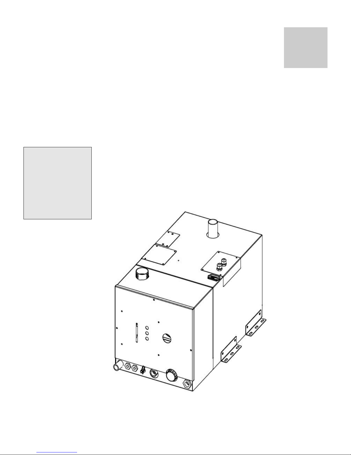
Thank you for purchasing The WindowWasher™ by ITR for portable hot
water window cleaning.
Some of the figures
in this manual
represent a typical
installation, but
other configurations
or methods may be
acceptable. If in
doubt, obtain
approval from ITR.
This section describes features of The WindowWasher™ by ITR and
covers critical information you need to know before beginning the
installation, including how to protect your warranty, and tools and
equipment needed.
Figure 1-1
International Thermal Research 1-1
Page 8

Section 1, Overview
1.1 Unpacking The WindowWasher™ by ITR
When you receive The WindowWasher™ by ITR:
1 Unpack it carefully.
2 Check each component against the provided parts list to ensure that
you have everything and that all parts arrived undamaged.
3 If you discover any missing or defective parts, call ITR immediately.
4 If you are not installing The WindowWasher™ by ITR right away,
secure all components so none will be misplaced.
5 Before installing The WindowWasher™ by ITR, read the rest
of Section 1 – Overview. It contains critical information for a
proper installation.
A properly installed WindowWasher™ by ITR is essential for several
reasons:
• To ensure that you and/or your customers receive satisfactory
results.
• To ensure a trouble-free installation, a successful inspection and
testing process and ease of future maintenance.
NOTICE
• To protect your Warranty.
1.2 Protect Your Warranty
This document reflects approved installation techniques, methods, and
materials, and applies only to ITR equipment. The WindowWasher™ by
ITR is only guaranteed by ITR if the entire system has been installed
according to the requirements and recommendations set out here.
Any modification must be approved in writing by qualified ITR
personnel, prior to the installation.
This includes:
• Deviations from the instructions in this Manual.
• Changes to any piece of ITR-supplied equipment.
• Substitution of a non-ITR-approved component.
1-2 The WindowWasher™ by ITR
Page 9

Section 1, Overview
No warranty will be extended to improper installations. Use of any
unapproved materials, equipment, or installation procedures will result
in a voided warranty for the entire heating system. ITR accepts no
liability for any
damage or loss of service resulting from unapproved
modifications.
• Efficient
• Clean
• Quiet
• Compact
• Safe
• Rugged
• Reliable
• Economical
1.3 The WindowWasher™ by ITR Features
The WindowWasher™ by ITR uses a patented diesel burner (12 VDC)
controlled by a multi-functional electronic controller as the primary
source of heating water. The WindowWasher™ by ITR heats water to
provide a continuous supply for all domestic hot water needs.
Other features of The WindowWasher™ by ITR include:
• A high-temperature, stainless steel burner and stainless steel
jacket.
• 5.3 US gallon ( 20.5 l) welded stainless steel insulated wate r tank
that minimizes heat loss and optimizes heat recovery.
• Low water level switch in the tank.
• Easy to install with hookups and connections easily accessible
from the top and front of The WindowWasher™ by ITR.
• Quiet operation and low power consumption.
• Low pressure fuel system with built-in fuel pump.
• Fuel efficient burner capable of burning a wide variety of diesel-
• Exhaust has minimal smoke or smell.
• Fan assisted sealed combustion chamber is designed to use
• Simple, low amperage draw ignition.
• Electronically-controlled system with:
International Thermal Research 1-3
based fuels.
outside air.
o Automatic Safety Shutdown.
o Manual reset aquasta ts for safety overheat protection.
o LED indicators on the Control Panel for diagnostics.
Page 10

Section 1, Overview
o Patented, proprietary flame sensor.
• The WindowWasher™ by ITR Remote Operating Panel with
ON/OFF switch for the diesel burner and indicator LED’s for
operational and diagnostic information.
1.4 Critical Factors
Pay attention to the
notices of “Danger”
“Warning” “Caution”
and “Notice” in this
manual.
The key factors to keep in mind when planning and carrying out the
installation are:
• Mounting location restrictions for The WindowWasher™ by ITR,
exhaust outlet (to reduce noise, vibration, heat loss, etc.)
• Length, routing, and sizing of fluid lines, fuel lines, air flow tubing,
exhaust piping and wiring.
• Unrestricted intake required to draw in outside air for combustion.
• Ability to easily access and service the product, especially fuel,
plumbing, and electrical systems.
• After installation, requirement to purge water and fuel lines and
inspect/test entire system using the ITR-supplied Inspection
Check Sheet.
1.5 Equipment, Tools and Skills
As the user and/or installer, you must be qualified and authorized to do
the installation, which requires mechanical aptitude and electrical
knowledge. Make sure you comply with existing industry practices,
using the highest and most recent standards and codes. Good
workmanship is essential. Please refer back to Section 1.2, Protect Your
Warranty.
You will need the following equipment and tools (not supplied) to install
the heating system. This list does not include optional equipment and
accessories:
• Standard tools normally available in a well-equipped shop.
• Appropriate fasteners for mounting the heater unit.
1-4 The WindowWasher™ by ITR
Page 11

Section 1, Overview
• Stainless steel 1-1/2” ID exhaust piping, maximum 12’ with no
bends (see Section 3 – Installing the Exhaust System, for details
when bends are present).
• ITR muffler.
• 1/4” supply and return fuel line, approved rubber or copper.
• Domestic water hose and/or tubing to connect The
WindowWasher™ by ITR hose fittings to the domestic water
system.
1.6 Testing and Inspection
After all components have been properly installed according to standard
practices, RVIA or ABYC standards, and the recommendations of this
Installation and Operating Manual, The WindowWasher™ by ITR should
be test-operated for inspection purposes.
For your convenience, you can use the pullout Inspection Check Sheet in
this Manual. The Inspection Check Sheet is divided into progressive
sections, allowing each phase of the inspection to be carried out
systematically, and then signed off by authorized persons.
International Thermal Research 1-5
Page 12

Section 1, Overview
1-6 The WindowWasher™ by ITR
Page 13

Section
2
Mounting - The WindowWasher™
2.1 Before You Begin
Plan the location of The WindowWasher™ by ITR and all its major
components in advance to ensure the chosen locations are feasible
and within the technical specifications.
Consider the following factors to help you decide exactly wher e best
to mount The WindowWasher™ by ITR:
• The WindowWasher™ by ITR weight when full.
! WARNING
• Ventilation requirements.
• Exhaust outlet location and maximum acceptable length.
• Thru hull location.
• Potential for vibration and jarring.
• Fuel storage location.
• Most efficient plumbing runs.
• Safe and convenient access for maintenance.
• Location of other equipment to be installed or connected to
The WindowWasher™ by ITR.
Make sure you are familiar with Section 1 – Overview of this M anual.
If the system is not installed according to specifications and with the
correct equipment, The WindowWasher™ by ITR may not operate
properly, safety may be compromised, and your Warranty may be
voided.
International Thermal Research 2-1
Page 14

Section 2, Mounting The WindowWasher™ by ITR
2.2 Your Mounting Location
Your mounting location should consider the following:
• Mounting location must be able to support double the gross
weight of The WindowWasher™ by ITR (i.e. 150 lbs. x 2 =
300 lbs/68 KG x 2 = 136 KG).
• The WindowWasher™by ITR is 14”H x 14”W x 24”D
(35.6 cm x 35.6 cm x 60.9 cm). See Figure 2-1:
Dimensions.
! CAUTION
The WindowWasher™ by ITR must not be installed in any compartment with flammable gases.
• The WindowWasher™ by ITR must be completely isolated
from living spaces. Combustion air must be drawn from a
100% outside source and cannot contain any combustible
gases.
• The WindowWasher™ by ITR must be mounted in an area
that provides unrestricted access to the front panel
mounted fuel and water connections, and top mounted
power and exhaust connection (minimum of 10” top
clearance – top exhaust version; and 3” clearance to all
other WindowWasher™ surfaces.
• The WindowWasher™ by ITR must not be installed in any
compartment with flammable gases.
• The WindowWasher™ by ITR must be mounted horizontal
and level using eight (8) x 1/4” through bolts using 1”
diameter fender washers, lock washers and nuts.
• It is recommended that a catchpan be placed under The
WindowWasher™ by ITR for containing any unexpected
leakage.
NOTICE
2-2 The WindowWasher™ by ITR
If The WindowWasher™ by ITR is going to be mounted in the engine
compartment, check for adequate ventilation. When the engine is
running, this area could be under a negative pressure. Make sure the
air intake and exhaust hoses have no leaks and are well-fastened to
the heater, muffler and thru hull fitting. Assembly parts that may
cause injury through accidental contact should be protected.
Page 15

Section 2, Mounting The WindowWasher™ by ITR
Isolate the unit in a closed compartment so that no air from the
heater will infiltrate the vehicle cab.
• Choose a sturdy surface in a location that won’t be unduly
affected by vibration and the jarring of rough roads or rough
seas.
• Mount the unit with the front panel side facing out and
accessible. Facing out simplifies installation and maintenance.
• Open access is required to properly service the heater. Leave
room at the front, and top of the unit.
• Ensure that the exhaust tubing can be properly and safely
routed to the outside. The maximum exhaust run for the
system is 12’.
Figure 2-1: Dimensions
2.3 Procedure
After choosing the mounting location for The WindowWasher™ by ITR:
International Thermal Research 2-3
Page 16

Section 2, Mounting The WindowWasher™ by ITR
1
Mount The WindowWasher™ by ITR horizontally and level.
2 Secure The WindowWasher™ by ITR in place (against the wall,
floor, or a mounting platform) using eight (8) x 1/4” through bolts
using 1” diameter fender washers, lock washers and nuts (See
Figure 2-2: Location of Mounting Brackets.).
Figure 2-2: Location of Mounting Brackets.
Insets: Bracket/Nut/Bolt Configurations
2-4 The WindowWasher™ by ITR
Page 17

Section
3
Installing the Exhaust System
3.1 Before You Begin
For efficient and safe operation of The WindowWasher™ by ITR
follow all recommendations for properly installing the exhaust.
Any deviations from these must be approved in advance by ITR.
Although the heater’s exhaust produces very low carbon
! DANGER
monoxide emissions, caution is still advised:
• Do not operate The WindowWasher™ by ITR in an
enclosed area unless there is adequate ventilation.
• Isolate The WindowWasher™ by ITR in a closed
compartment so that no air from the unit will infiltrate the
living areas.
Never place any exhaust parts close to combustible material or
through a combustible wall or ceiling without fireproof p rotection.
The exhaust can reach high temperatures.
3.2 Mounting Location
If you can’t meet the technical specifications for mounting the
exhaust, don’t use The WindowWasher™ by ITR. The unit may
perform poorly or become damaged if not installed according to
specifications.
Recommended Exhaust Outlet Locations
The following is recommended for a van exhaust outlet location:
• Mount the exhaust o utlet outside the van, not inside the
heater compartment. Otherwise, exhaust fumes could
infiltrate the van from The WindowWasher™ by ITR
compartment.
International Thermal Research 3-1
Page 18

Section 3, Installing the Exhaust System
• In a van, the typical mounting location for the exhaust
outlet is under the floor of the heater compartment, or on
the other side of the van, directly across from the heater
unit. Keep in mind you cannot exceed 12’ of exhaust
piping, including bends.
• Position the outlet of the exhaust pipe so that the exhaust
exits off the side of the van, not towards the front, back,
directly underneath the van, or under an openable
window, vent or sliding door.
Recommendation for Installation
• You may use sweep bends but each 90° bend is equ ivalent
to two feet of exhaust piping. For example, if you use two
90° bends you must deduct two feet per bend from the
maximum allowed 12’ straight exhaust pipe length.
Therefore you will be restricted to 8’ of straight exhaust
piping plus the two bends. Do not exceed these
recommendations.
! DANGER
• The combustion air-intake must use 100% outside air.
• Use an ITR-manufactured muffler or silencer; no other is
acceptable.
• Exhaust outlet is on the top or bottom of The
WindowWasher™ by ITR, towards the back.
The exhaust and outlet are HOT and the surrounding areas
must be thermally shielded and protected from the hot
surfaces and heat buildup by insulation. Nothing can come
into inadvertent contact with any part of the exhaust system
• Exhaust pipe must have a minimum of 3” (7.6 cm)
clearance from all surfaces.
• Ensure that the exhaust cannot be plugged or restricted.
• The exhaust fitting on The WindowWasher™ by ITR is
1.5” O.D. and the exhaust pipe used must have a
minimum of 1.5” I.D throughout its length.
• All exhaust elbows must be of a large radius design
(minimum radius 2.0”).
3-2 The WindowWasher™ by ITR
Page 19

Section 3, Installing the Exhaust System
• The exhaust must be supported a minimum of e very 3’ of
its installed length.
• The exhaust and The WindowWasher™ by ITR connection
point must use appropriate clamps and sealing compound
to ensure that the connections are tight and leak free. The
WindowWasher™ by ITR exhaust outlet pipe and the
exhaust pipe itself must not be distorted or damaged
during this process.
• With The WindowWasher™ by ITR running, the connection
points and the system must be checked for leaks and any
found must be corrected. Periodically, check the exhaust
fittings, connections, exhaust tube and insulation for leaks
and integrity and correct if required.
• Install an exhaust collar on the exhau st pipe to isolate the
pipe from the van.
What NOT to Do
Don’t mount the exhaust pipe inside the heater compartment.
Don’t use more than 12’ of total exhaust length (including
bends)
Don’t use mufflers with any flow restrictions.
Don’t over tighten exhaust clamps or you may crush The
WindowWasher™ by ITR’s exhaust spout.
3.3 Procedure
Figure 3-1 shows a standard setup for the up exhaust. To install
the exhaust system:
1 Leave suitable air spacing to protect combustible
materials; use an exhaust collar and metal shields where
required.
2 Securely seal the exhaust piping to The WindowWasher™
by ITR fitting using an approved exhaust clamp.
3 Connect the exhaust piping in series with the muffler,
using heavy-duty exhaust clamps. If you use vibration
isolation mounts they must be high temperature.
International Thermal Research 3-3
Page 20

Section 3, Installing the Exhaust System
4 Connect the air-intake tubing (2” I.D.) to the air-intake
fitting on top of the heater, and to an outside air-intake
fitting or dual thru hull (outside air only). Ensure t he run
of tubing is as short as possible to facilitate air flow.
5 Secure both ends of the air-intake tubing with properly
sized hose clamps to prevent air leaks.
6 Make sure the air-intake and exhaust hoses have no leaks
and are not touching each other.
Figure 3-1: Installing the Exhaust System (Up Exhaust)
3-4 The WindowWasher™ by ITR
Page 21

Section
4
Installing the Fuel System
4.1 Before You Begin
For efficient and safe operation of The WindowWasher™ by ITR,
follow all recommendations for properly installing the fuel system.
Any deviations from these recommendations must be approved in
advance by ITR.
! DANGER
! WARNING
Never use gasoline in The WindowWasher™ by ITR. Use only d iesel
I or diesel II fuel oil.
Keep fuel lines away from any heat source above 100°F (38°C).
Keep gasoline and any equipment that uses gasoline away from The
WindowWasher™ by ITR location. The WindowWasher™ by ITR is
not rated for use in an explosive environment.
Never share the fuel supply to The WindowWasher™ by ITR with
any other fuel-burning device.
4.2 Fuel System Installation
Recommendation for Installation
The WindowWasher™ by ITR’s fuel connections are accessed from
the front panel of the heater. The fuel inlet and fuel return are
labelled and located on the front lower face of The WindowWasher™
by ITR and are not interchangeable. These fittings consist of 1/8”
female NPT that connect to the fuel pump inside the units’ front
cover.
The following is recommended for the fuel system installation:
International Thermal Research 4-1
Page 22

The fuel supply
requires a dedicated
pickup line from the
main fuel tank. The
pickup must allow the
heater to run out of
fuel before the tank
itself is empty.
Section 4, Installing the Fuel System
• The fuel supply from the fuel storage tank to the fuel inlet
must be from a dedicated fuel pickup on the top of the tank.
• The fuel supply line should be installed with minimal rise
from the fuel tank. In no event should The WindowWasher™
by ITR be more than 60” above the fuel tank.
• The fuel return line should be installed from The
WindowWasher™ by ITR to the fuel tank.
• The fuel line must be run and secured so as to prevent
damage, chafing and kinking dur ing normal operation.
• All fuel line connection points and hoses must use suitable
clamps and/or sealant and must be checked for leaks on the
initial installation and also periodically as part of normal
maintenance.
• A primary, 10 micron UL and/or CSA approved fuel oil filter
(not provided) must be installed inline in the fuel su pply hose
between the tank and The WindowWasher™ by ITR, in a
manner that ensures easy access for maintenance. There is
also a small fuel filter behind the nozzle in the fuel block
inside The WindowWasher™ by ITR. Both filters must be
inspected and replaced as required as part of normal
maintenance.
• Fuel line hose used must be appropriate for your
requirements. It is strongly recommended that the hoses
have permanently installed end fittings.
4.3 What NOT to Do
• Don’t allow the fuel or the fuel lines to become con taminated
with foreign material.
• Don’t allow the fuel lines to become damaged or constricted.
4-2 The WindowWasher™ by ITR
Page 23

Section 4, Installing the Fuel System
Ensure that fuel lines are always protected from contamination by
foreign material. When installing or servicing, seal off ends to
prevent contamination. After installing, you may also wish to flush
the fuel line to rid of it air and any foreign material.
! CAUTION
Be sure that all fuel lines are secured and will not become pi nched,
kinked or damaged during normal operation.
4.4 Procedure
To complete the fuel system installation:
1 Install the inline fuel filter. The optimal location is on a
compartment wall next to The WindowWasher™ by ITR,
inline between the fuel tank and The WindowWasher™ by
ITR.
2 Connect the fuel line to the dedicated fitting on the main
diesel fuel tank.
3 Inspect the supply and return fuel line for any loose
connections or damage. Fittings must be airtight.
4 If desired, install a shut-off valve on the tank side of the
fuel filter to allow shutdown and filter service.
International Thermal Research 4-3
Page 24

Section 4, Installing the Fuel System
4-4 The WindowWasher™ by ITR
Page 25

Wiring the Electrical System
! WARNING
Section
5
5.1 Before You Begin
The WindowWasher™ by ITR and its electrical Control Board are
pre-wired and have been thoroughly tested together as a unit.
To review the wiring system for The WindowWasher™ by ITR, refer
to the schematic in this Section 5, Figure 5-1: System Wiring.
All electrical connections and wiring must comply with normallyaccepted 12 VDC wiring practices, local regulations and standards.
Only a qualified electrical installer should complete the wiring.
! WARNING
5.2 12 VDC
The following apply to the 12 VDC connections to the The
WindowWasher™ by ITR:
• There is one paired set of 12 VDC electrical connections on
the top right of The WindowWasher™ by ITR. They consist of
the primary DC positive (red) and negative (black) connection
and are 14 gauge stranded copper wires.
Primary DC power should originate from a dedicated connection on
the house battery bank. A 20 amp fuse or breaker must be included
inline from the battery to the positive (red) connection on The
WindowWasher™ by ITR. The primary power wire gauge must be
sized to permit no more than a 3% voltage drop from the battery to
The WindowWasher™ by ITR.
• A properly-shielded power system is required for safe,
trouble-free operation.
International Thermal Research 5-1
Page 26

Section 5, Wiring the Electrical System
5.3 Remote Operating Panel Cable
• The other connection on the top right of The WindowWasher™
by ITR is a short four (4) wire remote operating panel cable
with a four (4) pin connector. This connects to a matching
25’ connector cord that plugs directly into the Remote
Operating Panel. Refer to Figure 6-1: System Wiring.
NOTICE
Figure 5-1: System Wiring
5.4 Main Electronic Control Board
• The main electronic Control Board is mounted on board The
WindowWasher™ by ITR itself. It has no user adjustable
components.
5.5 What NOT to Do
Never shut off The WindowWasher™ by ITR power via an inline
battery or master switch while the system is running. Never
disconnect the battery when The WindowWasher™ by ITR is
running, and never disconnect the battery while the inverter is
charging.
5-2 The WindowWasher™ by ITR
Page 27

Section 5, Wiring the Electrical System
Doing either will severely damage The WindowWasher™ by ITR
because it fails to automatically purge the combustion chamber.
Such damage is detectable upon inspection and will not be covered
under warranty. Always shut the system off using the normal
system controls, after it has completed its purge.
International Thermal Research 5-3
Page 28

Section 5, Wiring the Electrical System
5-4 The WindowWasher™ by ITR
Page 29

Section
6
Plumbing the System
6.1 Before You Begin
For efficient and safe operation of The WindowWasher™ by ITR,
follow all recommendations for properly installing the plumbing
system. Any deviations from these must be approved in advance by
ITR.
6.2 Plumbing Installation
NOTICE
Do not operate The
WindowWasher™ by
ITR until water is in
the WindowWasher™
and heating system,
and all trapped air
has been bled.
Figure 6-1: Plumbing Fittings
International Thermal Research 6-1
Page 30

NOTICE
All fittings on the
WindowWasher™
require two
wrenches when
tightening.
Section 6, Plumbing the System
The plumbing installation should consider the following:
• All fittings on The WindowWasher™ by ITR require two
wrenches when tightening. One wrench must be placed on
the tank fitting and held in place to prevent this fitting from
being overstressed. The other wrench can be used to tighten
the matching half of the fitting onto it. Failure to follow this
procedure will damage The WindowWasher™ by ITR and the
fittings.
NOTICE
All fittings, hose
and/or tubing
involving the
domestic water
component of the
distribution module
(optional) must be
approved for use with
domestic water
• All fittings, hose and/or tubing involving the domestic water
must be approved for use with domestic water and rated for
the domestic water system pressure. The working pressure
limit of The WindowWasher™ by ITR tank is 150 psi.
• All plumbing lines must be run and secured so as to preven t
damage, chafing and kinking.
• The WindowWasher™ by ITR sh ould be filled and flushed prior
to operation to remove any foreign debris.
• The WindowWasher™ by ITR is supplied with a
temperature/pressure relief valve and drain fitting. This
valve drains through the drain relief hose located at an
opening on the left front lower face of The WindowWasher™
by ITR and is labeled “Temp/Pressure Relief Valve”. Do not
block or plug the valve or the hose. See the label attached
onto the drain relief hose for the proper utilization and
routing of this hose (see next page).
6-2 The WindowWasher™ ITR
Page 31

Section 6, Plumbing the System
NOTICE
The WindowWasher™
is supplied with a
temperature and
pressure relief valve
and drain relief hose.
This valve drains
through the drain
relief hose located at
an opening on the
left front lower face
of the
WindowWasher™ and
is labeled
“Temp/Pressure
Relief Valve”. Do not
block or plug the
valve or the hose.
See the label
attached onto the
drain relief hose for
the proper utilization
and routing of this
hose.
IT IS CONNECTED TO THE COMBINATION TYPE TEMPERATURE AND
PRESSURE SAFETY RELIEF VALVE AT THE TANK. PROPER INSTALLATION IS
REQUIRED.
Discharge line should terminate through plain (unthreaded) pipe with at least a 6”
(152mm) air gap from a location where any discharge will be clearly visible. In no
case may a discharge line be directly conne cted to a sewer line . No reduc ing coupling
or other restriction shall be installed in the discharge line. The discharge line shall be
installed to allow complete drainage of both the v alve and the discharge line. The
discharge line must be installed in a continuously downward direction a nd in a frost
free environment. Water may drip from the discharge line. The discharge line must be
left open to atmosphere. Discharge line material must conform to local plumbing
codes or ASME requirements. Excessive length over 30’ (9.14m), use of more then
four elbows, or reducing discharge line size will cause a restriction and reduce the
discharge capacity of the valve. The pressure re lief valve is to be operated regulare ly
to remove lime deposits and to verify that it is not blocked. Temperature and
pressure safety relief valve should be inspected at least once every three years and
replaced, if necessary. See tag attached to the valve for additional instructions.
CAUTION! THIS IS A DISCHARGE LINE!
• Heater hose — PEX tubing. Slip-on foam insulation
coverings may be used over the hose fittings to reduce
heat loss. Secure all hose connections with spring clamps.
• Air vents — Air vents for the fluid circu lation system are
not supplied, but may be optionally installed to help bleed
air from the system.
NOTICE
6.3 What NOT to Do
Don’t use low-quality heater hose.
Don’t let the hose come into contact with solvents, which may
cause it to soften and swell. If there is any risk that solvents may
contact the hose, insert it into PVC plastic tubing for protection.
6.4 Installation Procedure
To install and connect The WindowWasher™ by ITR:
1 The supply and return plumbing connections are on the front
lower face of The WindowWasher™ by ITR and are 1/2” female
NPT fittings. The supply input is labeled “Cold Water Inlet” and
the hot water output is labeled “Hot Water Outlet”. Ensure
proper direction of flow.
International Thermal Research 6-3
Page 32

Section 6, Plumbing the System
r
The
r
f
2 Two male 1/2” NPT PEX tube fittings (not supplied) must be fit
into the supply and return fittings and tightened to a leak free
condition.
3 Connect the domestic water holding tank to the Cold Wate
Inlet. In some installations, a check valve may have to be
obtained and installed on the cold input line to
WindowWasher™ by ITR to prevent warm water from
backfilling to the water storage tank. Check the appropriate
standards and regulations. Ensure there are no kinks or sharp
bends that might restrict the fluid flow. If bends are required
for PEX tubing, fit the tubing into a plastic bend support. Do
not use rubber heater hose for potable water plumbing.
4 Connect the hot water supply line to the Hot Water Outlet.
Ensure there are no kinks or sharp bends that might restrict
the fluid flow. If bends are required for PEX tubing, fit the
tubing into a plastic bend support. Do not use rubber heater
hose for potable water plumbing.
5 A drain point, labeled “Drain” is provided on the front lowe
middle face of The WindowWasher™ by ITR and consists of a
thumb valve.
6 A suggested procedure for filling The WindowWasher™ by ITR
is to close The WindowWasher™ by ITR drain valve, open the
highest hot water faucet in the domestic water system, open
the valve to the cold water inlet to The WindowWasher™ by ITR
and then allow to fill. Once the water is flowing in a steady
stream from the hot water faucet, close the faucet.
7 To drain the WindowWasher™ by ITR, have the outlet of the
pressure relieve valve and the outlet of the drain valve go into
a bucket or to a drain where it will not create a mess. Open the
drain valve and open the pressure relief valve and allow all o
the water to drain from the tank. Once the water has been
drained, close the pressure relief valve and the drain valve.
6-4 The WindowWasher™ ITR
Page 33

Section
7
Operating The WindowWasher™
7.1 Operating Instructions for The
WindowWasher™ by ITR
This section describes the operation and maintenance of your new
WindowWasher™ by ITR.
The WindowWasher™ by ITR must be installed and connections
NOTICE
made in accordance with the recommendations in the Installation
and Operating Manual prior to operating The WindowWasher™ by
ITR.
Figure 7-1: The WindowWasher™ by ITR - Fittings
International Thermal Research 7-1
Page 34

Section 7, Operating the WindowWasher
7.2 Turning the Power to The
WindowWasher™ by ITR “ON”
• The WindowWasher™ by ITR’s Control Panel located on the
WindowWasher™ itself contains three push buttons: ON/OFF
power, Bypass and Reset. The power switch must be pushed
ON (power LED will turn ON) to turn the DC electrical power
to the main Control Board and WindowWasher™ ON and is
required to be left ON during any period where heat is
requested. When The WindowWasher™ by ITR is shut down
for any extended period or the season it is recommended that
the power switch be turned OFF.
7.3 Activating the Burner
NOTICE
Do not operate the
WindowWasher™
until it is filled
with water and all
trapped air has
been bled.
Activating the Burner
The burner switch on the Remote Operating Panel controls the
ON/OFF of the diesel burner (primary heat source). When the
burner switch is turned ON, the diesel portion of The
WindowWasher™ by ITR will turn on after ten seconds. The Burner
LED on the Remote Operating Panel will turn ON when the diesel
burner has been activated. The burner will continue to operate until
the water in The WindowWasher™ by ITR reaches the set operating
temperature range. At this point, the diesel burner will turn OFF. If
The WindowWasher™ by ITR water should cool to outside of this
temperature range, the burner will again come on and will continue
until either the burner switch on the Remote Operating Panel is
turned OFF or the temperature range is again achieved. If the
burner switch on the Remote Operating Panel is turned OFF, the
burner stops and The WindowWasher™ by ITR enters a two minute
cool down stage prior to completely shutting down.
7.4 Functions of the Remote Panel
• The WindowWasher™ by ITR’s Remote Operating Panel,
Figure7-2: Remote Operating Panel, contains one ON/OFF
burner switch and three LED’s indicating Burner activation,
AC element activation(not available), and service.
7-2 The WindowWasher™ by ITR
Page 35

Section 7 , Operating the WindowWasher
Figure 7-2: Remote Operating Panel
Burner Switch
• The burner switch controls the ON/OFF of the diesel burner.
The Burner LED will turn ON when the diesel burner has been
activated.
Burner LED (Green)
• When ON, indicates the diesel burner has been activated.
AC Heat LED (Green)
• Not used
Service LED (Red)
• When ON, indicates T he WindowWasher™ by ITR has faulted.
The specific fault can be identified by examining the
WindowWasher™ Control Panel located on the
WindowWasher™. There are three red and six green indicator
LED’s on this panel. Refer to the description of the
WindowWasher™ Control Panel for further details.
7.5 Functions of The Control Panel
The WindowWasher™ by ITR’s Control Panel, Figure 7-3:
WindowWasher™ Control Panel, contains three push buttons:
ON/OFF power, Bypass and Reset. In addition, it contains nine
LED’s indicating Power, AC Heat, Air Compressor, Fuel Pump,
Combustion Fan, Igniter, Flame Fault, Voltage Fault and Low Water
Level Fault.
International Thermal Research 7-3
Page 36

Section 7, Operating the WindowWasher
Figure 7-3: The WindowWasher™ by ITR - Control Panel
Power On/off Button
• The Power On/Off button turns ON/OFF the power to the
WindowWasher™ Control Board. The Power LED (green)
turns ON when the power to the control board is ON.
Bypass Button
• The Bypass button is for authorized service personnel only.
Reset Button
• The Reset button when pressed resets the WindowWasher™
Control Board.
Power LED (Green)
• The Power LED (green) turns ON when the power to The
WindowWasher™ by ITR Control Board is ON. The LED flashes
when the WindowWasher™ is in bypass mode.
7-4 The WindowWasher™ by ITR
Page 37

Section 7 , Operating the WindowWasher
AC Heat LED (Green)
• Not installed
Compressor,Fuel Pump, Combustion Fan, Igniter LED (Green)
• The air Compressor, Fuel Pump, Combustion Fan an d Igniter
LED’s (green) turn ON when the component is ON, and will
flash if the component is electrically open or shorted.
Flame Out LED (Red)
• The Flame Out fault LED (red) turns ON when a flame fault
has been detected.
Voltage LED (Red)
• The Voltage fault LED (red) turn s ON wh en a voltage fault has
been detected.
Low Water LED (Red)
• The Low Water level fault LED (red) turns ON when a low
water level in the WindowWasher™ has been detected.
7.6 Maintenance
Customer Monthly Maintenance: Check the following and
correct as required:
• Water hoses and fittings for leaks and integrity.
• Exhaust fittings, connections, tubes for leaks, and integrity.
• Exhaust and air-intake checked for no obstructions.
• Fuel lines, fittings for leaks and integrity.
• External fuel filter for clogging.
Annual Factory Maintenance: Perform the following:
• Factory Service Tune-up (DC power is disconnected):
• Prior to operation for the season, a factory service
International Thermal Research 7-5
tune-up of the modular system should be performed by
trained service personnel. Only personnel familiar with
the equipment modules should perform the service tune-up.
It is recommended that the dealer be contacted for this
service or if not available, contact ITR for further instructions.
Page 38

Section 7, Operating the WindowWasher
• As a general guide, the regular maintenance items such as
the igniter, fuel nozzle, fuel filters (internal and external) and
air filter (internal) should be replaced as opposed to inspected
and cleaned. Their performance may be deteriorating and/or
their remaining service life ending without any apparent
visual signs or operating symptoms.
• The major components such as the air compressor, fuel
pump, and combustion air fan should be examined for wear
and should be replaced by the service technician as required.
They are not serviceable and must be replaced.
• The combustion tube should be inspected by the service
technician for wear and replaced if necessary. If the tube is
satisfactory, a thorough cleaning of the tube and burner
chamber should be performed.
• The domestic water mixing valve on the WindowWasher™
should be inspected every year and replaced if necessary.
See the tag attached to the valve for additional instructions
(see below).
This ____ Mixing Valve must be installed and adjusted per the supplied instruction sheet.
It must be installed in accordance with applicable plumbing codes. To insure that the
valve keeps working properly, periodically turn the handwheel a full number lower
(higher) than the set number. If yo u do not detect a noticeable decrease ( increase)
in the discharge temperature, service the valve immediately. Otherwise, turn the
handwheel back to the original setting.
This ____ valve was installed _______. The handwheel was set to number : ______.
Any change in the setting to a higher numb er may raise the discharge temperature
to an unsafe temperature which may lead to scalds.
• The temperature and pressure safety relief valve on the
WindowWasher™ should be inspected every year and
replaced if necessary. See the tag attached to the valve for
additional instructions (see below).
DO NOT REMOVE THIS TAG FROM VALVE.
WARNING:
FAILURE TO COMPLY WITH THESE INSTURCTIONS REGARDING THIS VALVE CAN
RESULT IN SERIOUS PERSONAL INJURY OR DEATH AND/OR SEVERE
PROPERTY DAMAGE.
WARNING: Following installation, the valve lever MUST be operated AT LEAST ONCE A
YEAR by the water heater owner to ensure that waterways are clear. Certain
naturally occurring mineral deposits may adhere to the valve, blocking waterways,
rendering it inoperative. When the lever is operated, hot water will discharge if the
waterways are clear. PRECAUTIONS MUST BE TAKEN TO AVOID PE RSONAL INJURY
FROM CONTACT WITH HOT WATER AND TO AVOID PROPERTY DAMA GE. BEFORE
operating lever, check to see that a discharge line is connected to this valve,
directing the flow of hot water from the valve to a proper place of disposal. If no
7-6 The WindowWasher™ by ITR
ANNUAL OPERATION OF T& P RELIEF VALVES
Page 39

Section 7 , Operating the WindowWasher
water flows when the lever is operated, replacement of the valv e is required. TURN
THE WATER HEATER “OFF” (see instruction manual) AND CALL A PLUMBER
IMMEDIATELY.
REINSPECTION OF T & P RELIEF VALVES:
WARNING: Temperature and Pressure Relief Valves should be inspected AT LEAST ONCE
EVERY THREE YEARS, and replaced, if ne cessary, by a licensed plumbing contractor
or qualified service technician, to ensure that the product ha s not been affected by
corrosive water conditions and to ensure that the valve and discharge l ine have not
been altered or tampered with illeg ally. Certain naturally occurring condition s may
corrode the valve or its components over time, rendering the valve inoperative.
Such conditions can only be detected if the valve and its componen ts are physically
removed and inspected. Do not attempt to conduct an inspection on your own.
Contact your plumbing contractor for a reinspection to assure continuing safety.
WARNING: FAILURE TO REINSPECT THIS VALVE AS DIRECTED COULD RESULT
IN UNSAFE TEMPERATURE OR PRESSURE BUILD-UP WHICH CAN RESULT IN
SERIOUS INJURY OR DEATH AND/OR SEVERE PROPERTY DAMAGE.
If discharge occurs, CALL A PLUMBER IMMEDIATELY. Discharge may ind icate that a n
unsafe temperature or pressure condition exists whi ch requires immediate attention
by a qualified service technician or licensed plumbing contractor.
SEE WATER HEATER INSTRUCTION MANUAL FOR ADDITIONAL INFORMATION
REGARDING THE TEMPERATURE AND PRESSURE RELIEF VALVE.
See other side for important information
WARNING: To avoid water damage and/or scalding due to valve operation, a d ischarge
line must be connected to valve outlet and run to a safe place of disposal. The
discharge line shall be installed to allow complete drainage of both the valve and the
discharge line. No reducing coupling or other restriction shall be installed in the
discharge line. The discharge line must pitch downward from the valve and
terminate with a 6" (152mm) air gap from an approved location or building drain.
The discharge line must terminate through plain (unthreaded) p ipe. Discharge line
material must conform to local plumbing code or A.S.M.E. requirements. Excessive
length – more than 30 feet (9.14m), use of more than four elbows or bends in
discharge piping, or reduction of discharge line size will cause a restriction and
reduce the discharge capacity of the valve. No shut-off valve should be installed
between the relief valve and tank, or in the discharge line.
To ensure proper operation, this valve must be installed by a qualified service technician
or licensed plumbing contractor in accordance with these instructions and local
plumbing codes and standards.
WARNING:
FAILURE TO COMPLY WITH THESE INSTRUCTINS REGARDING THIS VALVE CAN
RESULT IN SERIOUS PERSONAL INJURY OR DEATH AND/OR SEVER
PROPERTY DAMAGE.
Combination temperature and pressure relief valves with extension thermostats must b e
installed so that the temperature-sensing ele ment is immersed in the water in the
top 6" (152mm) of the water storage tank. They must be installed either in the hot
outlet service line or directly in a tank tapping. Valves must be located so as to
assure isolation from flue gas heat or other ambient conditions that are not indicative
of stored water temperature. See other instructions regarding the discharge line.
This device is designed for emergency safety relief and must not be used as an operating
Repair or alteration of valve in any way is pro hibited by national safety standards/local
International Thermal Research 7-7
control.
codes.
Page 40

Section 7, Operating the WindowWasher
• Regular inspection and maintenance are a necessary part of a
properly operating module and satisfactory performance.
7.7 Protect the WindowWasher™
• Protect The WindowWasher™ by ITR from temperature
extremes and any dusty, dirty, corrosive environment.
• Protect The WindowWasher™ by ITR from cold temperatures
and corrosion.
• Note that any domestic water in The WindowWasher™ by ITR
will freeze in cold temperatures and will damage the
components. The WindowWasher™ by ITR and all associated
components must be completely drained of the domestic wa ter
and emptied before freezing temperatures are encountered.
7.8 General Troubleshooting
Insure that The WindowWasher™ by ITR has both
sufficient battery voltage and water level as The
WindowWasher™ is designed not to allow operation if
either are incorrect (indicated by lit Voltage Fault or Low
Water Level Fault LED’s on The WindowWasher™ Control
Panel) .
Burner Does Not Start Up
• WindowWasher™ connected to 12 VDC power?
• Power On/Off button on WindowWasher™ Control Panel pushed
ON? Power LED lit on Remote Operating Panel?
• Burner switch on Remote Operating Panel ON?
• Fuses or circuit breakers blown or tripped?
Burner Starts but Flame Faults
• Fuel supply present and adequate?
• Air-intake or exhaust not blocked or obstructed?
• Air in fuel line (White smoke from exh aust)?
• Fuel filter (external) dirty?
• Component LED’s all glowing green on T he WindowWasher™
Control Panel?
7-8 The WindowWasher™ by ITR
Page 41

Section
8
Warranty And Service
8.1 Warranty
Warranty cards must be filled in completely, signed by the
Owner and Dealer and returned to ITR within 30 days of the
date of the original installation.
ITR warrants the HURRICANE®II/IIL/COMBI, SCH25, Water
Heater and WindowWasher by ITR (referred to as
“heater(s)”) and all accessories or other supplied components with
the original purchase to be free of defects in materials and
workmanship under design usage and service conditions for two (2)
years from the heater serial number label manufacturing date.
Warranty replacement parts are covered for the remainder of the
heater’s warranty.
This warranty does not apply to damage or failure of the
heater, or the vessel or vehicle into which it was installed,
due to improper installation, assembly, maintenance, or
abuse, accident, or the use of parts not supplied by ITR.
8.2 Installations
The purchaser and installer are advised that specific rules and
regulations may be in effect with respect to the installation of the
“heater”. It is the installer’s responsibility to review and comply with
all such rules and regulations.
Non-standard installations, that is, those requiring a departure from
published installation instructions, should not be undertaken without
first having consulted and obtained the written approval of ITR.
Coverage for warrantable parts will, at the discretion of ITR, be
made to the claimant in the form of repair, replacement, or credit.
“Heaters” installed using non standard, industry accepted
procedures and without ITR’s or an authorized Dealer’s
approval will be limited to a 90 day warranty measured from
the heater serial number label manufacturing date.
International Thermal Research 8- 1
Page 42

Section 8, Warranty
8.3 Limited Warranty
The following warranties are in lieu of all other warranties
and conditions. ITR makes no other warranties,
representations, or conditions, express or implied, and there
are expressly excluded all implied or statutory warranties or
conditions of merchantability of fitness for a particular
purpose and those arising by statute or otherwise in law of
from a course of dealing or usage of trade.
The stated express warranties are in lieu of all liabilities or
obligations for damages arising out of or in connection with
the delivery, use, performance, or licensing of the product or
in connection with any services performed. In no event
whatsoever, shall ITR be liable for indirect, consequential,
exemplary, incidental, special or similar damages including
but not limited to lost profits, lost business revenue, failure
to realize expected savings, other commercial or economic
loss of any kind or any claim against ITR by any other party
arising out of or in connection with the sale, delivery, use,
performance, or repair or in connection with any services
performed, even if ITR has been advised of the possibility of
such damages, whether based upon warranty, contract, or
negligence. ITR’s maximum liability shall not in any case
exceed the contract price for the products claimed to be
defective. ITR warranties its products; ITR authorized
dealers/service centers and installers provide warranty for
installation. Any warrantable service and or labour is the
responsibility of ITR and should be performed by an authorized
dealer unless other arrangements are authorized.
No one is authorized to increase, alter, or enlarge ITR’s
responsibilities or obligations under these warranties.
Warranties are void if the original serial number has been
removed or altered, or cannot be readily determined.
8-2 Installation Manual for Window Washer by ITR
Page 43

Section 12, Warranty
8.4 Owner’s Responsibilities
Before the expiration of the warranty, the Owner must give
notice to a registered ITR Dealer of failures, if any,
considered to be warrantable and deliver the defective
“heater” to such dealer. The Owner is responsible for all repairs
made to the engine, equipment, vessel, or vehicle in which the
“heater” is installed, other than the “heater”. The Owner is
responsible for lodging, meals, and other incidental costs incurred by
the Owner as a result of a warrantable failure. The Owner is
responsible for “down time” expenses, and all business costs and
losses resulting from a warrantable failure.
ITR IS NOT RESPONSIBLE FOR INCIDENTAL OR
CONSEQUENTIAL DAMAGES.
8.5 Not Covered Under Warranty
This warranty will not apply to:
• Normal usage, wear, and tear on parts, including but not limited to,
fuel filter, air filter, nozzle, fuses, igniter, and carbon brushes.
• Parts or products which malfunction due to improper installation
including but not limited to malfunctions causing inadequacies in;
air, fuel or coolant flow, voltage due to wiring, shock or vibration.
• Any progressive damage to the engine, vessel, or vehicle arising out
of failure of the “heater”.
• “Heaters” which have been modified or use of non-standard parts
not approved by ITR.
• “Heaters” that have been abused, damaged, vandalized, or received
improper maintenance.
• Removal and re-installation expenses of the “heater” unless
specific written permission has been obtained from ITR.
,
• Travel time and expenses incurred by an ITR dealer or other
personnel to perform warranty related work on the “heater”
International Thermal Research 8 - 3
Page 44

Section 8, Warranty
• Diagnosis or repairs when caused by problems not directly related to
the “heater” or due to empty fuel tanks or poor fuel quality, fuel
additives, acidic water, electrolysis, incorrect vessel bonding leading
to abnormal corrosion.
• Running the system dry or without appropriate preservatives
(antifreeze), causing damage to the heat exchanger, pump seals,
etc.
• Exposing the heater to an environment detrimental to its effective
operation (such as excessively wet, dirty, or hot areas).
• Other products which ITR does not manufacture.
• Any products or parts which have been used in a manner contrary
to ITR’s printed instructions.
PLEASE FOLLOW THE RECOMMENDATIONS INCLUDED IN THIS
MANUAL.
8.6 Customer Service Calls
Normal service calls are at the owner’s expense.
CHECK THE TROUBLESHOOTING CHAPTER OF THIS MANUAL
TO SEE IF YOUR PROBLEM IS ADDRESSED.
When calling with a service problem, please have the following
information at hand:
• The model number and serial number of your heater and main
electronic control board.
• If your heater is already installed, ensure you are familiar with
the design and installation setup.
• Have ready a detailed description of the problem and keep the
manual handy to refer to.
8.7 Returns
To obtain warranty service, the owner must:
• Provide a full description of the problem to your dealer and ITR.
ITR will determine if the problem is covered under the ITR
warranty.
8-4 Installation Manual for Window Washer by ITR
Page 45

Section 12, Warranty
• If ITR determines that the problem is covered under warranty,
they will provide you with a Repair or Return Goods Authorization
(RGA) number for any warranty return, repair or service.. ITR will
refuse any return package without a proper RGA number.
• If ITR determines that “heater” repairs will be covered under
warranty under in-field conditions, ITR will authorize the in-field
warranty service personnel as to specific conditions and limits for
parts and labor used in the repair. Any other incurred costs will not
be covered under the warranty.
• When shipping your product, pack securely to prevent damage,
indicate the RGA and serial number of the heater on the outside of
the shipping container, and ship prepaid and insured to ITR.
• In the shipping container, provide written details of the problems,
RGA number, manufacturing date as indicated by the serial
number label, serial number, proof of purchase, and a return
address.
After repair or replacement
of products under warranty, ITR will
return the product to the customer via standard (non expedited)
delivery. Factory repairs or replacement will be done as quickly as
possible, with an estimated five working day turn around.
8.8 Telephone Service
There is no charge for help or service information given over the
telephone or by fax. Any recommendation or advice from ITR or any of
its employees, or Dealers, is given only in good faith as an
accommodation to the customer. Such information should not be relied
upon by the customer without an independent verification of its
applicability to the customer’s particular situation. For customer service
or other information:
Call the Dealer from whom you bought the heater, or call ITR
IN CANADA: IN THE UNITED STATES:
th
2431 Simpson Road, 11915 NE 56
Circle Suite B
Richmond, BC Canada V6X 2R2 Vancouver, WA USA 98682
Tel: 1-800-755-1272 or 604-278-1272 Tel: 1-800-993-4402 or 360-993-4877
Fax: 604-278-1274 Fax: 360-993-1105
Email: info@itrheat.com Website: http://www.itrheat.com
International Thermal Research 8 - 5
Page 46

Section 8, Warranty
PLEASE FILL OUT FOR YOUR OWN REFERENCE
8-6 Installation Manual for Window Washer by ITR
 Loading...