


Current transducer
User manual and technical documentation
Document version:
1
Update:
05.05.2017
Safety information
National and local electrical safety regulations must always be followed.
Improper operation of the device or its application to purposes different from the intended use
may pose hazards to operators and /or may lead to the equipment damage.
Exploration of damaged device can result in malfunction of protected object and result in threat
to life and health.
Reliable and defect-free operation of the device needs appropriate transportation, handling,
storage, installation and commissioning as well as correct operation and maintenance.
Whenever changes are made in the device, measures should be taken to avoid inadvertent
tripping.
Comments
We reserve the right to modify the device.
Device is an industrial monitoring and control instrument.
Remaining user documentation can be downloaded from energetyka.itr.org.pl.

Contents:
1. Introduction 4
Symbols ........................................................................................................................................... 4 1.1.
2. General Information 5
3. Extensions 7
SEM SB11 ........................................................................................................................................ 8 3.1.
Panels .............................................................................................................................................. 9 3.2.
3.2.1. PAN 1 ..................................................................................................................................... 9
3.2.2. PAN 3 ................................................................................................................................... 10
Optional accessories ..................................................................................................................... 11 3.3.
3.3.1. SPS 24-1 ............................................................................................................................... 11
3.3.2. SEM Cxx ............................................................................................................................... 12
3.3.3. SEM Bxx - binary inputs and outputs ................................................................................... 13
4. Operating the device 14
5. Disturbance recorder 15
6. Wiring diagrams 16
7. Remarks of manufacturer 17
Maintenance, inspections, repairs ................................................................................................ 17 7.1.
Storage and transport ................................................................................................................... 17 7.2.
Place of installation ....................................................................................................................... 17 7.3.
Disposal ......................................................................................................................................... 17 7.4.
Guarantee ..................................................................................................................................... 17 7.5.
8. Additional information 18
Description of communication interfaces .................................................................................... 18 8.1.
9. Order specification 20
10. Contact 21
IU_26779_1_ENG_MANUAL_SEMSC11 3 / 21

Electrical warning symbol indicates the presence of hazardous energy circuits or electric shock
hazards.
The warning symbol indicates the important information related to the threat to life and health.
The information symbol indicates the clarification of relevant features and parameters of the
device.
1. Introduction
Symbols 1.1.
4 / 21 IU_26779_1_ENG_MANUAL_SEMSC11
The SEM SC11 device is a component of a Smart Station Control system. Is designed for monitoring,
control and diagnostics of different type of switching devices.
The logic of operation of Smart Control SEMSC11 is based on the ELF application and can be
freely edited by the user, which makes it possible to design a control algorithm for any type
commutating device.
Name
Colour
Description
STATUS
yellow
continuous light – indicates correct operation of the device
no light – a failure has been detected by the self-control algorithm
POWER
green
continuous light – indicates correct supply voltages
no light – indicates incorrect supply voltages.
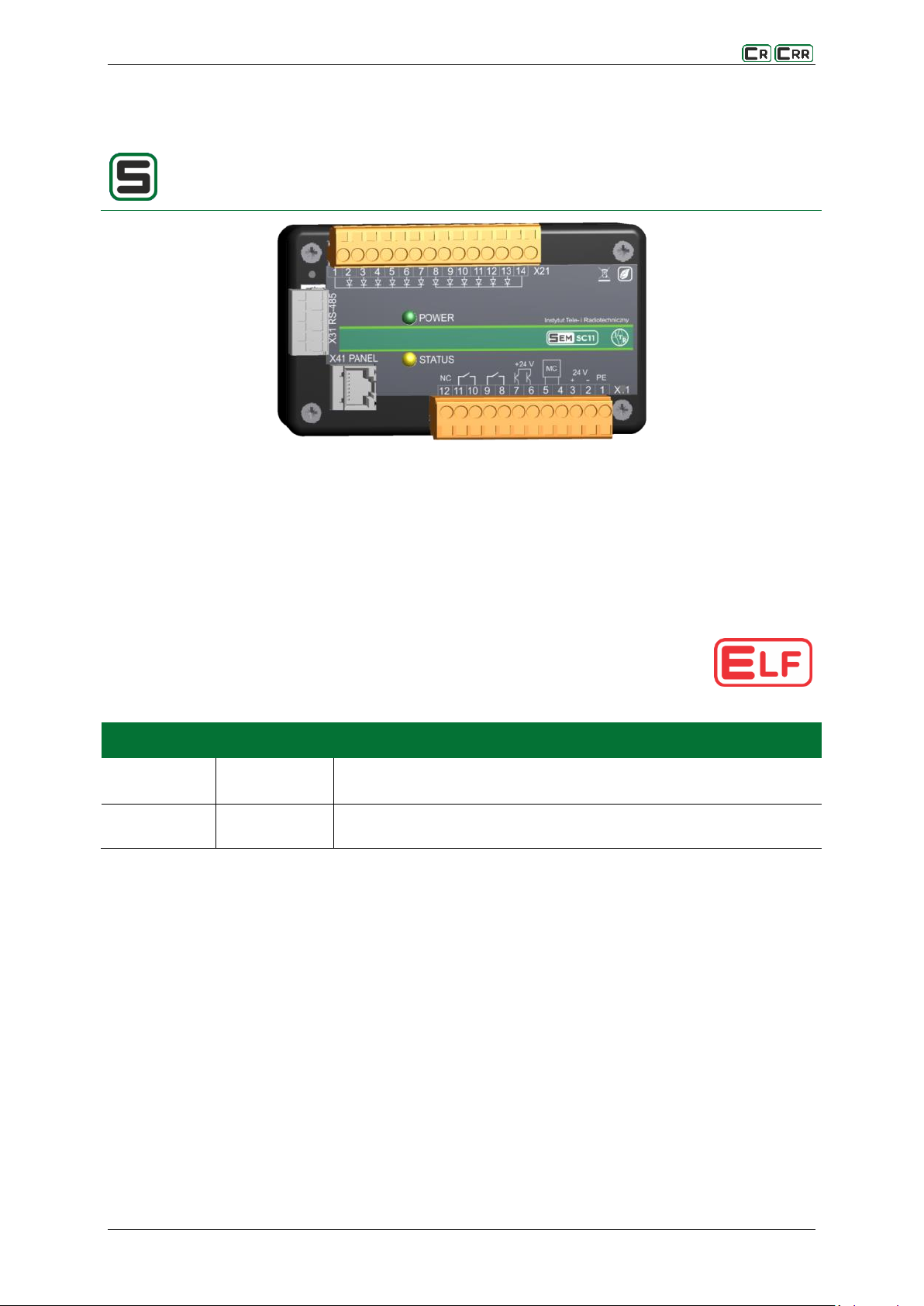
2. General Information
Fig. 2.1. View of the panel of SEM SC11
The unit can be controlled through the output (MC - Motor Control) with a reversible polarity rated up to 30 A.
To improve the security and reliability of the device control, the following modules were implemented:
algorithm of return to the secure state after a failed commutating cycle;
measurement and control of the drive control current;
commutating cycle recorder with the time registration of 20s.
Table 2.1. Meaning of predefined diodes:
The scope of functionality of the MODBUS-RTU protocol:
Controlling switching devices;
Reading i/o states;
Performing a sequence of pre-sending and object-oriented tests with validation of the test
performance.
IU_26779_1_ENG_MANUAL_SEMSC11 5 / 21

Characteristics and functionality of SEM SC11:
12 or 14 binary inputs,
2 transistor DC 24 V binary outputs,
two enhanced relay-semiconductor binary outputs for direct control of switching devices,
one relay-semiconductor binary output with a variable polarity for direct control of the commutating
device drive (control current up to 30),
measurement of the drive control current;
supply voltage measurement,
the RJ45 link for the PAN 1 or PAN 3 operator panel,
the RS-485 link for communication with a telemechanics driver or the SEM SB11 device - the MODBUS-
RTU protocol,
self-monitoring functions (STATUS led)
reprogramming functions (through both transmission ports),
programmable logic, including algorithms for monitoring and control of the commutating device,
test profile for diagnosing the correct operation of the device,
algorithm of return to the secure state after a failed commutating operation;
commutating operation recorder with the registration time of 20s.
remote and local modes of operation.
The following applications are used for configuring and reprogramming the device:
ELF – Parametrisation, logic design, driver status display,
FlashArm – reprogramming the driver,
appSC – specialized application tool adapted to the SEM SC11 to configure basic parameters, change
the profile of logic and view the state of binary inputs and outputs.
6 / 21 IU_26779_1_ENG_MANUAL_SEMSC11
operator
supply from
telemechanics
control
supply
SPS 24-1
supply switch
AK 1
USB-RS485 converter
Operator panel
Switch with 24 V DC
closer
3. Extensions
A typical driver consists of the central module SEM SC11. The module has two links: X31 (RS-485) for
connecting with the telemechanics or module SEM SB11 and X41 (PANEL) for connecting the HMI Panel.
The device operation can be monitored and controlled through both links. The telemechanics functions can be
performed by the SEM Cxx module which is equipped with tools for communication with SCADA systems. For
local control of the device, PAN 1 or PAN 3 type detachable operator panels are used.
All modules are supplied with DC 24 V. If there is a separate power supply in the switchgear for
the commutating device control and the telemechanics, use the SPS 24-1 type power switch which switches the
SEM SC11 to the standby power (from the telemechanics) in the absence of a control voltage.- In this case,
the control of the switch is blocked, but its status can be monitored and data exchange with the telemechanics
is possible.
IU_26779_1_ENG_MANUAL_SEMSC11 7 / 21

Expansion module SEM SB11 acts as a RS-485 converter for binary signals. It provides an interface for
the exchange of information between the module SEM SC11 and the telemechanics driver
or increases the functionality of the driver for managing the switching apparatus by additional binary
inputs and outputs.
Name
Colour
Description
POWER
green
steady light – indicates correct supply voltages
no light – indicates incorrect supply voltages.
STATUS
yellow
steady light – no transmissions from the SEM SC11 device
intermittent light – indicates correct operation of the device
no light – a failure has been detected by the self-control algorithm
SEM SB11 3.1.
Fig. 3.1. View of the panel of SEM SB11
Characteristics and functionality of SEM SB11:
2 binary inputs for controlling (remotely) switching devices from the telemechanics,
10 transistor DC 24 V binary outputs designed to transmit the operating status of switch ing devices to
the telemechanics,
RS-485 link for communication with the SEM SB11 device (MODBUS-RTU protocol),
self-monitoring functions (STATUS led)
Table 3.1. Meaning of predefined diodes
8 / 21 IU_26779_1_ENG_MANUAL_SEMSC11

For local control of the device, PAN 1 or PAN 3 type detachable operator panels are used.
Symbol/N
ame
Colour
Description
green
Indicates that the correct supply voltage has been applied. Steady light.
OPENED
green
Indicates an open connector. Steady light.
CLOSED
red
Indicates a closed connector. Steady light.
FAIL
yellow
Indicates the connector failure status. Steady light.
REMOTE
yellow
Indicates the permission for the remote control. Steady light.
LOCAL
yellow
Indicates the permission for the local control. Steady light.
OFF
yellow
Indicates the lack of a permit to control. Steady light.
Symbol
Description
Control for the switch closing
Control for the switch opening
Change of the control location (local, remote, no control)
Panels 3.2.
3.2.1. PAN 1
Fig. 3.2. View of the front panel PAN 1
The PAN1 panel is the smallest in the series of panel and is intended for mapping the status of the switches,
controlling the switches, and changing the control mode. The user interface consists of 7 signalling LEDs and
three buttons.
Table 3.2. Meaning of predefined diodes
Table 3.3. The use of buttons
IU_26779_1_ENG_MANUAL_SEMSC11 9 / 21

Name
Colour
Description
POWER
green
Steady light - the correct supply voltage of the controller and the panel.
STATUS
yellow
Intermittent light - correct interaction between the driver and the panel.
Steady light - no interaction between the controller and the panel.
Symbol
Description
Control for the switch closing
Control for the switch opening
Contextual buttons - assign displayed on the screen
3.2.2. PAN 3
Fig. 3.3. View of the front panel PAN 3
Panel PAN 3 presents a visualisation of the status of the distribution box on a 2.8 inch graphic display.
In addition to the basic information on the panel state, such as switch states, measurements or control mode,
it displays additional information, i.e. communication port parameters, settings, event log, alarms, etc.
The functionality of the communication interface depends on the parameters of the device to which
it interacts. The user interface consists of two signalling LEDs, five buttons and a colour TFT display.
Table 3.4. Meaning of predefined diodes
Table 3.5. The use of buttons
10 / 21 IU_26779_1_ENG_MANUAL_SEMSC11

Device SPS24-1 is used for switching power supply voltage 24 V DC.
Name
Colour
Description
In1_OK
yellow
indicates operation with the supply voltage from input In1
Out
green
indicates the presence of output voltage DC 24 V
Optional accessories 3.3.
3.3.1. SPS 24-1
Fig. 3.4. SPS 24-1
At the output of the device marked Out, there is the power supply from inputs In1 or In2. The voltage
at the output marked Out comes from the input In2 when it is applied only to In2. If voltages are present
at both inputs or only at input In1, the power comes from the input In1. The status of operation on the power
supply from In1 is confirmed by the voltage presence at In1_OK. An important feature of the device is
the galvanic insulation between supply circuits.
Table 3.6. Meaning of predefined diodes
IU_26779_1_ENG_MANUAL_SEMSC11 11 / 21
SEM Cxx is a central module of the SEM system. It is equipped with tools for communication with
SCADA systems.
Module type
Communication ports
1 RS 232 port
3 RS 422/485 ports
2 Ethernet ports
1 USB port
GSM modem
1 RS 232/422/485 port
1 Ethernet port
1 USB port
Protocols
DNP 3.0,
IEC 60870-5-104,
MODBUS-TCP,
MODBUS RTU
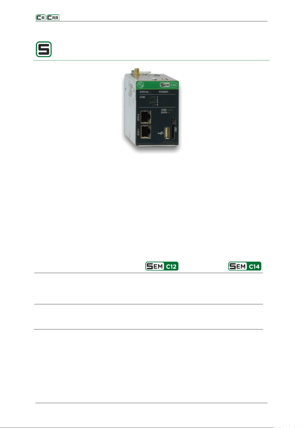
3.3.2. SEM Cxx
Fig. 3.5. Module SEM C12
The module communicates with the parent system by means of DNP 3.0, IEC 60870-5-104 or MODBUS
communication protocols and using GSM, Ethernet and RS 232/422/485 links. Thanks to the interaction
with the ELF application tool, the controller operation can be fully programmed, for example:
Inspection of the temperature increments in distribution panels.
Control and monitoring of the status of switches in MV panels.
Current and voltage protections.
Automation – monitoring and enforcing of the state of binary inputs.
The module acts as a data hub with all elements of the SEM system and is connected with these elements
via the bus. This enables a remote configuration of modules and software exchange as well as the registration
of events in the log.
Table 3.7. Comparison of SEM Cxx central modules
12 / 21 IU_26779_1_ENG_MANUAL_SEMSC11

SEM Bxx extends the system with binary inputs and outputs, their state is represented with
the LEDs located on the front panel. The readout and analysis of input and output states is done
using the main controller module SEM Cxx .
Module type
Description
8 binary inputs and 8 binary outputs
16 binary inputs and 16 binary outputs
16 binary inputs
32 binary outputs
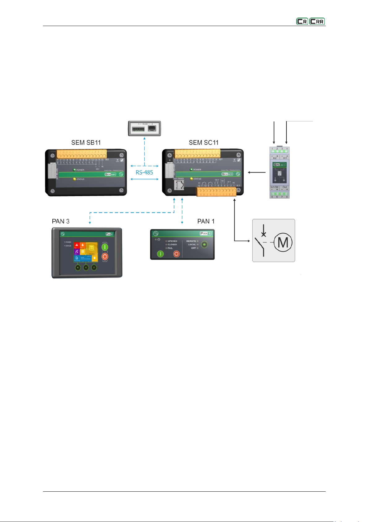
Telemechanics
controller
Telemechanics
controller
Fig. 3.6. Flowchart illustrating the interaction with the telemechanics
a) via binary inputs / outputs with the SEM SB11 module
B) via RS-485 link
3.3.3. SEM Bxx - binary inputs and outputs
Fig. 3.7. Module SEM B23
Table 3.8. Comparison of the binary input and output module SEM Bxx
IU_26779_1_ENG_MANUAL_SEMSC11 13 / 21

The local control of the device is described by means of the type PAN 1 detachable operator
panel.
The selected control location is stored in the SEM SC11 controller.
After the power supply is restored, the last selected state is also restored.
In the absence of the ability to control the switching apparatus as resulting from a jam in the
control procedure (a blocking of the switching apparatus) in a transient state, the device has a
mechanism for local and remote unlocking of switches with the “open” button.
The logic of operation of the device is based on the ELF software and is freely editable by the
user.
4. Operating the device
Button allows you to change the control location: Remote, Local, Off. By pressing the button a cyclical
change of control position is made: Remote -> Local -> Off -> Remote -> …
The selected control location is indicated by the corresponding LED.
Control mode: LOCAL - local operator control
If there are no control locks (resulting from the operation logic), buttons , generate pulses of a certain
duration to the output controlling the switching apparatus.
Control mode: REMOTE - telemechanics control
Action of buttons , is overridden. The switch control takes into account the control interlocks resulting
from the logic of operation implemented in the controller, via communication links located in the controller.
Control mode: OFF - no control capability
The action of buttons , and control commands from the telemechanics are overridden – control lock.
14 / 21 IU_26779_1_ENG_MANUAL_SEMSC11

5. Disturbance recorder
The SEM SC11 device is fitted with a disturbance recorder that has access to volatile memory (vDAR)
and non-volatile memory (sDAR) areas. The resources provided allow for 15 seconds of recording with 100ms
resolution. The record contains the following data:
binary inputs and outputs of the device,
output current values for motor control,
supply voltage values;
8 optional binary signals applied to the control block,
link status at start and end of registration,
counters of the number of OPEN / CLOSE commutating operations performed,
a registry containing a failure type tag.
Fig. 5.1. Recorded waveform of the switch control operation
The recorder control is done using the function block placed on the logic diagram. If the recorder is active,
the appearance of a rising edge on the input starts the logging during which the data are stored in the volatile
memory. If a rising edge appears on one of the failure detection inputs during the logging, the entire waveform
will be rewritten to non-volatile memory. Only one (the first detected) waveform of an incorrect switching
cycle is saved in the non-volatile memory, . The readout and visualization of recorded waveforms is done
by means of a special utility software (appSC), which also allows the saved waveform to be saved
in non-volatile memory, allowing the next waveform to be saved. In Fig. 5.1., an example of the recorded
switch control operation is shown.
IU_26779_1_ENG_MANUAL_SEMSC11 15 / 21

6. Wiring diagrams
Fig. 6.1. SEM SC11 device’s wiring diagram (12 inputs)
Fig. 6.2. SEM SC11 device’s wiring diagram (14 inputs)
Fig. 6.3. SEM SB11 device’s wiring diagram
16 / 21 IU_26779_1_ENG_MANUAL_SEMSC11

The device implements programmed operation of protection, control and automatic functions algorithms,
and it was fitted with autotest systems responding to internal damage during device operation.
The manufacturer recommends that correctness of device operation is verified:
a) each time - during commissioning,
b) at least once a year - in mine face installations,
c) at least once every 5 years in installations other than front face.
Also inspections resulting from branch regulations should be undertaken.
Changes in protections set points during operation do not require verification of their correctness.
Devices are packed in transport packages and secured against damage during transport and storage. Devices
should be stored in transport packages, indoors, in places free from vibrations a nd direct effects of weather
conditions, dry, well ventilated, free from harmful vapors and gases. Ambient air temperature should be
between –35°C and +85°C, and relative humidity should not exceed 80%.
SEM SC11 and SEM SB11 are designed for setting up on 35 mm DIN rail. Mounting of PANx and accessories
are described in separate documentation. The total length of the connected wires must not exceed 3 m.
Products are made mostly from recyclable materials, or materials that can be processed again or disposed
of in environmentally sound manner. Decommissioned devices can be collected for recycling, provided that
their condition is that of normal wear and tear. All components that are not recyclable shall be disposed
of in environmentally sound manner.
Regular guarantee period is 36-month. Had the sale been preceded by execution of an Agreement between
the Buyer and the Seller, provisions of such Agreement shall apply. Guarantee covers remedying of defects,
free of charge, provided that instructions specified in the Warranty Card are adhered to. Detailed guarantee
conditions may be found at energetyka.itr.org.pl in the w „Sale Regulations”.
The guarantee period is counted from the date of sale.
The warranty is extended by a period of residence of the product in the repair.
Unauthorized tampering with the product will void the warranty.
Warranty does not cover damage resulting from improper use of the product.
7. Remarks of manufacturer
Maintenance, inspections, repairs 7.1.
Storage and transport 7.2.
Place of installation 7.3.
Disposal 7.4.
Guarantee 7.5.
IU_26779_1_ENG_MANUAL_SEMSC11 17 / 21

The SEM SC11 is equipped with two communication links to connect with the a panel and the SB11
extension module or a telemechanics controller.
In addition, both links allow parametrization and view of the operating status of the controller
using the ELF, FlashArm or appSC utility software.
USB 2x RS-485 converter type AK 1 is dedicated for connecting the SEM SC11 with a computer via
any communication port.
8. Additional information
Description of communication interfaces 8.1.
The RS-485 standard and the MODBUS RTU protocol at 115kbps are implemented on the communication
interfaces. The X31 socket is normally used to connect with the SEM SB11 expansion module or telemechanics
controller.
Depending on the connection point of the device within the network, following types of connections are used:
Type I – intermediate position – without RT resistor matching wave impedance of the line;
Type II – extreme position – with RT resistor matching wave impedance of the line.
Above connection types are implemented in the by means of suitable wiring of 10-pin WAGO type 734-110
connector.
On X31 socket a pins 1 and 2 are short circuited (line A) and also a pins 3 and 4 (line B), making it easy to
connect controllers to the communication network. Devices can have an address from 1 to 247.
X41 socket (PANEL) is used to communicate with PAN 1 or PAN 3 operator panels. The connection method is
shown in Figure 8.4.
Fig. 8.1. Type I – intermediate position – without RT resistor matching wave impedance of the line
18 / 21 IU_26779_1_ENG_MANUAL_SEMSC11

Fig. 8.2. Type II – extreme position – with RT resistor matching wave impedance of the line
Fig. 8.3. Connection between SEM SC11 and SEM SB11 modules
Fig. 8.4. Connection between SEM SC11 and PAN 1 or PAN 3 operator panel
IU_26779_1_ENG_MANUAL_SEMSC11 19 / 21

A B P
Wersion
12 binary inputs
12
14 binary inputs and current measurement
14
Extension module
none 0
SEM SB 11
1
Panel
none
0
PAN 1
1
PAN 3
3
Accessory
□ SPS 24-1
□ AK1 - USB – 2xRS485 converter
□ Telemechanics controller SEM Cxx
9. Order specification
Order example:
SC: A12 B0 P0 - 12 inputs
SC: A12 B0 P1 - 12 inputs; PAN1
SC: A14 B1 P3 - 14 inputs; SB11 and PAN1
SC: A14 B1 P0; SPS 24-1 - 14 inputs; SB11 and SPS 24-1
20 / 21 IU_26779_1_ENG_MANUAL_SEMSC11

Tele- and Radio Research Institute
ICT and Electronics Centre
03-450 Warsaw, ul. Ratuszowa 11
tel.: + 48 22 590 73 91
e-mail: energetyka@itr.org.pl
www: energetyka.org.pl
10. Contact
IU_26779_1_ENG_MANUAL_SEMSC11 21 / 21
 Loading...