


1
1
Introduction
ETX620-B
Carrier Board
User’s Manual
935-ETX620-000G
A01800724

2
Introduction
1
Copyright
This publication contains information that is protected by copyright.
No part of it may be reproduced in any form or by any means or
used to make any transformation/adaptation without the prior written permission from the copyright holders.
This publication is provided for informational purposes only. The
manufacturer makes no representations or warranties with respect to
the contents or use of this manual and specifically disclaims any express or implied warranties of merchantability or fitness for any particular purpose. The user will assume the entire risk of the use or the
results of the use of this document. Fur ther, the manufacturer reserves the right to revise this publication and make changes to its
contents at any time, without obligation to notify any person or entity of such revisions or changes.
© 2007. All Rights Reserved.
Trademarks
Product names or trademarks appearing in this manual are for identification purpose only and are the properties of the respective owners.

3
1
Introduction
FCC and DOC Statement on Class B
This equipment has been tested and found to comply with the limits
for a Class B digital device, pursuant to Part 15 of the FCC rules.
These limits are designed to provide reasonable protection against
harmful interference when the equipment is operated in a residential
installation. This equipment generates, uses and can radiate radio frequency energy and, if not installed and used in accordance with the
instruction manual, may cause harmful interference to radio communications. However, there is no guarantee that interference will not
occur in a particular installation. If this equipment does cause harmful
interference to radio or television reception, which can be determined
by turning the equipment off and on, the user is encouraged to try
to correct the interference by one or more of the following measures:
• Reorient or relocate the receiving antenna.
• Increase the separation between the equipment and the receiver.
• Connect the equipment into an outlet on a circuit different from
that to which the receiver is connected.
• Consult the dealer or an experienced radio TV technician for
help.
Notice:
1. The changes or modifications not expressly approved by the
party responsible for compliance could void the user's authority
to operate the equipment.
2. Shielded interface cables must be used in order to comply with
the emission limits.

4
Introduction
1
Table of Contents
Warranty.................................................................................................
Static Electricity Precaution................................................................
Safety Measures.....................................................................................
About the Package...............................................................................
Chapter 1 - Introduction....................................................................
Chapter 2 - Hardware Installation....................................................
System Board Layout............................................................................................................
Jumper Settings............................................................................................................................
Rear Panel I/O Ports.............................................................................................................
I/O Connectors..........................................................................................................................
5
6
6
7
8
9
9
10
16
24

5
1
Introduction
Warranty
1. Warranty does not cover damages or failures that arised from
misuse of the product, inability to use the product, unauthorized
replacement or alteration of components and product specifications.
2. The warranty is void if the product has been subjected to physical abuse, improper installation, modification, accidents or unauthorized repair of the product.
3. Unless otherwise instructed in this user’s manual, the user may
not, under any circumstances, attempt to perform service, adjustments or repairs on the product, whether in or out of warranty.
It must be returned to the purchase point, factory or authorized
service agency for all such work.
4. We will not be liable for any indirect, special, incidental or
consequencial damages to the product that has been modified
or altered.

6
Introduction
1
Static Electricity Precautions
It is quite easy to inadvertently damage your PC, system board,
components or devices even before installing them in your system
unit. Static electrical discharge can damage computer components
without causing any signs of physical damage. You must take extra
care in handling them to ensure against electrostatic build-up.
1. To prevent electrostatic build-up, leave the board in its anti-static
bag until you are ready to install it.
2. Wear an antistatic wrist strap.
3. Do all preparation work on a static-free surface.
4. Hold the device only by its edges. Be careful not to touch any of
the components, contacts or connections.
5. Avoid touching the pins or contacts on all modules and connectors. Hold modules or connectors by their ends.
Important:
Electrostatic discharge (ESD) can damage your processor,
disk drive and other components. Perform the upgrade instruction procedures described at an ESD workstation
only. If such a station is not available, you can provide
some ESD protection by wearing an antistatic wrist strap
and attaching it to a metal part of the system chassis. If a
wrist strap is unavailable, establish and maintain contact
with the system chassis throughout any procedures requiring ESD protection.
Safety Measures
To avoid damage to the system:
• Use the correct AC input voltage range
..
..
.
To reduce the risk of electric shock:
• Unplug the power cord before removing the system chassis
cover for installation or servicing. After installation or servicing,
cover the system chassis before plugging the power cord.
Battery:
• Danger of explosion if battery incorrectly replaced.
• Replace only with the same or equivalent type recommend
by
the manufacturer.
• Dispose of used batteries according to local ordinance.

7
1
Introduction
About the Package
The package contains the following items. If any of these items are
missing or damaged, please contact your dealer or sales representative for assistance.
; The system board
; A user’s manual
; One IDE cable
; One bracket mounted with a COM port
; One I/O shield
; One QR (Quick Reference)
The board and accessories in the package may not come similar to
the information listed above. This may differ in accordance to the
sales region or models in which it was sold. For more information
about the standard package in your region, please contact your
dealer or sales representative.

8
Introduction
1
Audio
IDE
Display
LFP (Local Flat
Panel) LVDS
Temperature
Humidity
Rear Panel I/O
Ports
I/O Connectors
Expansion Slots
ETX
Connectors
PCB
• 2 channel line-out audio output
• Supports up to Ultra ATA 100
• Supported IDE devices:
a. Two IDE connectors support up to 4 IDE devices; or
b. 3 IDE devices (IDE 2 = Slave only) + 1 CF card (Master
only)
Note: We do not recommend using IDE devices and CF card at
the same time.
• Dedicated LFP (Local Flat Panel) interface
• Analog display
• Integrated PWM interface for LCD backlight inverter control
• Operating: 0
o
C to 60oC
• Non-operating: -40
o
C to 60oC
• Operating: 10% to 90%
• 1 mini-DIN-6 PS/2 mouse port
• 1 mini-DIN-6 PS/2 keyboard port
• 1 parallel port
• 1 DB-9 serial port
• 1 DB-15 VGA port
• 1 RJ45 LAN port
• 4 USB 2.0/1.1 ports
• Mic-in, line-in and line-out jacks
• 1 connector for an external serial por t
• 1 LCD brightness control connector (optional)
• 1 LVDS LCD panel connector
• 1 LCD/inverter power connector
• 1 IrDA connector
• 2 40-pin IDE connectors
• 1 floppy connector
• 1 20-pin ATX power connector
• 1 Wake-On-Ring connector (optional)
• 1 Wake-On-LAN connector
• 1 front panel connector
• 1 CompactFlash socket (Master only)
• 4 PCI slots
• 3 ISA slots
• Four ETX connectors
• 4 layers, ATX form factor
• 30.48cm (12") x 20cm (7.8")
Chapter 1 - Introduction
Specifications

2
9
Hardware Installation
Chapter 2 - Hardware Installation
System Board Layout
1
Front
WOL
1
PCI 1
PCI 2
PCI 3
PCI 4
1
2
39
40
LVDS LCD Panel
ATX po we r
11
2010
1
1
1
1
1
COM 2
IrDA
1
Mouse
KB
1
WOR
1
2
56
1
Parallel
LAN
USB 1
USB 0
USB 3
USB 2
Mic-in
Line-in
Line-out
COM 1
Parallel
VGA
1
2
5
6
1
1
2
99
100
1
99
2 100
1
2
99
100
2100
1
99
ETX-X3
VGA, LCD (LVDS),
COM 1&2, LPT, IrDA,
KB, Mouse (CN3)
ETX-X4
IDE 1&2, LAN
Others (CN1)
ETX-X1
PCI, USB,
Audio (CN2)
ETX-X2
ISA (CN7)
LCD brightness
(J14)
LCD/Inverter
power
IDE 2
IDE 1
FDD
CompactFlash socket
Battery
ISA 1
ISA 2
ISA 3
panel
2
11
12
KB lock
(JP5)
1
2
5
6
1
1
LPT/FDD select
(JP2)
Panel power
select (JP12)
COM2
RS232/422/
select (JP9)485
COM2
RS232 AUX
select (JP10)
1
CPU fan
1
2nd fan
1
System
fan
Diagnostic LED
Standby
Power LED
2
10
Hardware Installation
Parallel
Parallel
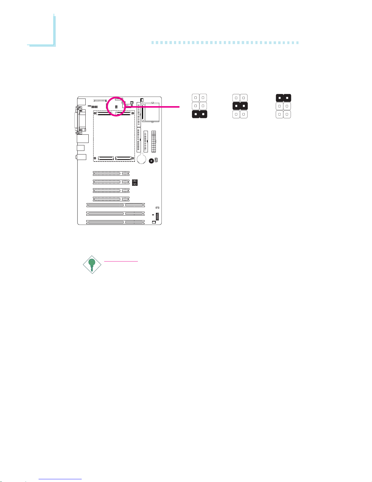
Panel Power Select
X
JP12
JP12 is used to select the power supplied to the LCD panel.
Important:
Before powering-on the system, make sure JP12’s setting
matches the LCD panel’s specification. Selecting the incorrect
voltage will seriously damage the LCD panel.
1-2 On:
12V
3-4 On:
5V
5-6 On:
3V (default)
Jumper Settings
1
3
2
6
4
5
1
3
2
6
4
5
1
3
2
6
4
5

2
11
Hardware Installation
Parallel
LCD Brightness Control (Voltage Level Adjust) - optional
X
J14
Use J14 to connect to the LCD Brightness Control button of the
LCD Display Panel. It is used to adjust the brightness of the LCD
Display Panel. Increasing or decreasing the voltage to control the
LCD panel’s brightness varies among Inverters. You must refer to the
Inverter’s specification to make the appropriate adjustment to the
brightness of the LCD panel.
1-2 On:
Increases the voltage level
2-3 On:
Decreases the voltage level
1
3
2
12
Hardware Installation
Parallel
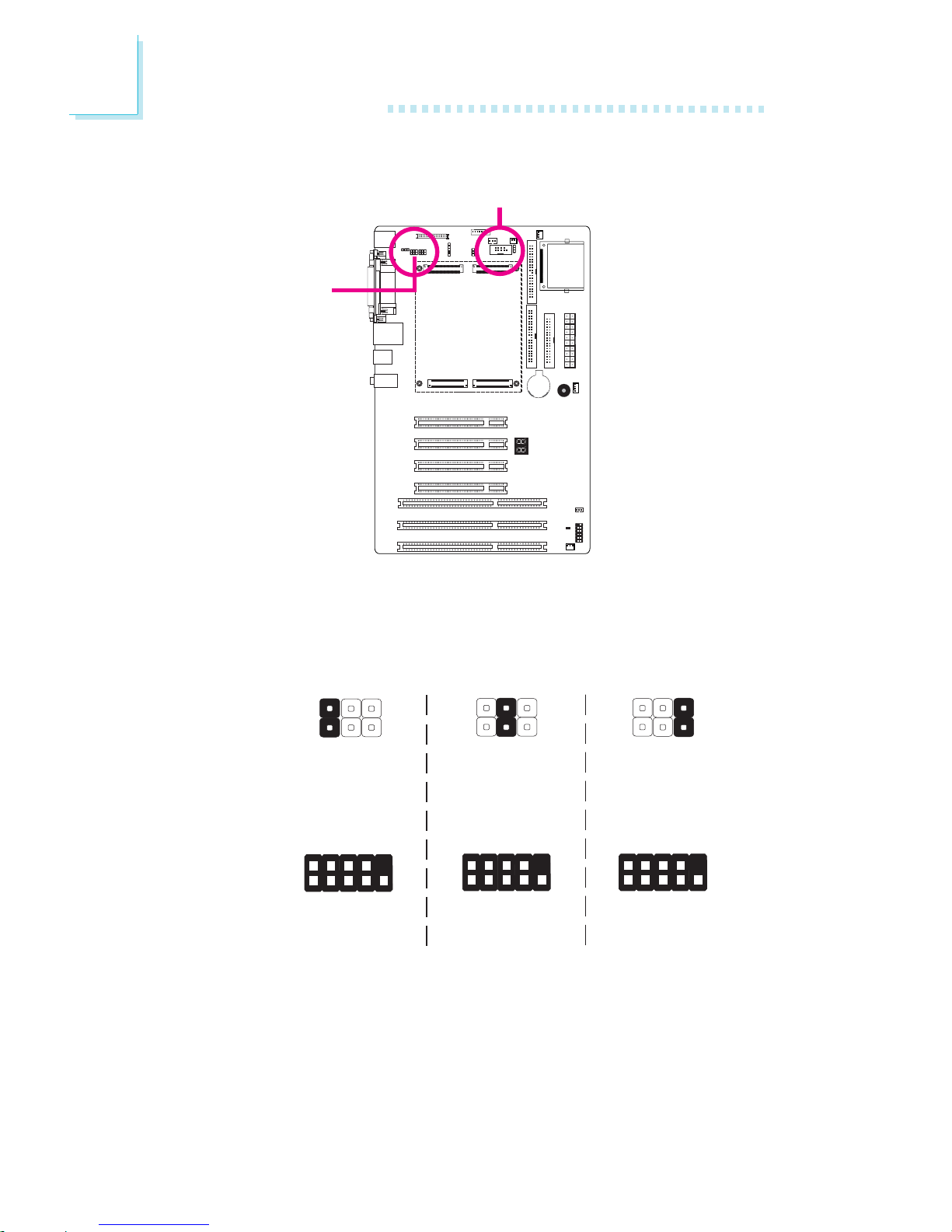
COM 2 RS232/RS422/RS485 Select
JP9 is used to configure the COM 2 serial port to RS232, RS422
(Half Duplex) or RS485.
The pin function of COM 2 will vary according to JP9’s setting.
1-2 On:
RS232
(default)
6
5
1
2
1
9
2
DCD-
TD
RD
DTR-
GND
RTS-
DSR-
CTS-
RI-
JP9
COM 2
JP9
COM 2
5-6 On:
RS485
6
5
1
2
3-4 On:
RS422
Full Duplex
6
5
1
2
1
9
2
RXD+
TXD+
RXD-
N. C.
N. C.
N. C.
TXD1
N. C.
N. C.
1
9
2
DATA+
N. C.
DATA-
N. C.
N. C.
N. C.
N. C.
N. C.
N. C.

2
13
Hardware Installation
Parallel
By default, JP10 sets COM 2 to RS-232. If the serial device connected to this port requires 5V/12V power from the system board,
set JP10 pins 3-5 and 4-6 to On.
The table below list the pin assignment of JP10.
COM 2 RS232/AUX Select
1
3
5
MRI2-
X_MRI2-
+12V
2
4
6
MDCD2-
X_MDCD2-
Vcc
3-5 (12V),
4-6 (5V) On:
RS232 with power
1-3, 2-4 On:
RS232 standard
(default)
31
4526
31
4526
X
JP10

2
14
Hardware Installation
Parallel
LPT/FDD Select
X
JP2
1-2 On:
LPT (default)
2-3 On:
FDD
JP2 is used to select between using LPT and FDD.
1
3
2
1
3
2

2
15
Hardware Installation
Parallel
Parallel
KB Lock Select
JP5
X
132
132
1-2 On:
KB enabled
(default)
2-3 On:
KB locked
JP5 is used to enable or disable the keyboard lock function.

16
2
Hardware Installation
The rear panel I/O ports consist of the following:
• PS/2 mouse port
• PS/2 keyboard port
• Parallel port
• COM port
• VGA port
• LAN port
• 4 USB ports
• Mic-in jack
• Line-in jack
• Line-out jack
Rear Panel I/O Ports
PS/2
Mouse
LAN
Parallel
USB 3
USB 0-1
COM
VGA USB 2PS/2
K/B
Line-out
Line-in
Mic-in

17
2
Hardware Installation
Parallel
PS/2 Mouse and PS/2 Keyboard Ports
The onboard PS/2 mouse (Green) and PS/2 keyboard (Purple)
ports are used to connect a PS/2 mouse and a PS/2 keyboard
respectively.
W
PS/2 Mouse
PS/2 Keyboard

18
2
Hardware Installation
Parallel
Parallel
W
Parallel Port
The onboard standard parallel port (Burgundy) is for interfacing your
PC to a parallel printer.
Note:
FDD and LPT share the same channel therefore you can only
use one device at a time. Even when you are using one device
only, please do not connect a device to the other connector.
Use JP2 to select between using FDD and LPT. FDD is internally fixed in Slave mode.

19
2
Hardware Installation
Parallel
Serial Ports
The system board is equipped with an onboard serial port (COM
1). It is also equipped with a 9-pin connector (COM 2) for connecting an external serial por t. The serial ports are RS-232/RS-485 asynchronous communication ports.
To connect COM 2, please refer to the following description. The
serial port may be mounted on a card-edge bracket. Install the cardedge bracket to an available slot at the rear of the system chassis
then insert the cable connector to COM 2. Make sure the colored
stripe on the ribbon cable is aligned with pin 1 of COM 2.
W
COM 1
1
9
2
DCD
TD
RD
DTR
GND
RTS
DSR
CTS
RI
COM 2
W

20
2
Hardware Installation
Parallel
VGA Port
The VGA port is used for connecting a VGA monitor. Connect the
monitor’s 15-pin D-shell cable connector to the VGA port (Blue).
After you plug the monitor’s cable connector into the VGA port,
gently tighten the cable screws to hold the connector in place.
VGA
W

21
2
Hardware Installation
Parallel
RJ45 LAN Port
The onboard RJ45 LAN port allows the system board to connect
to a local area network by means of a network hub.
W
LAN

22
2
Hardware Installation
Parallel
Universal Serial Bus Connectors
The four onboard USB 2.0/1.1 ports (Black) allow data exchange
between your computer and a wide range of simultaneously accessible external Plug and Play peripherals.
W
USB 1
USB 0
USB 3
USB 2
W
23
2
Hardware Installation
Parallel
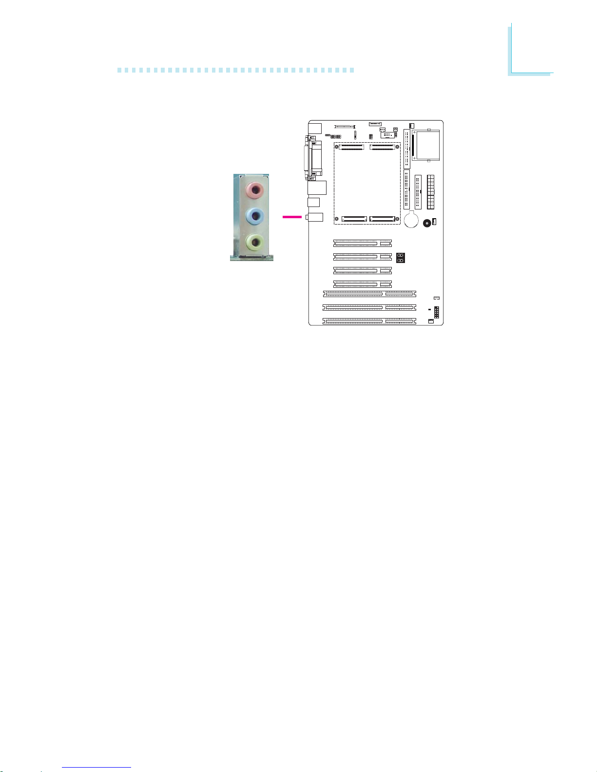
Audio
The system board is equipped with 3 audio jacks. A jack is a onehole connecting interface for inserting a plug.
• Mic-in Jack (Pink)
This jack is used to connect an external microphone.
• Line-in Jack (Light Blue)
This jack is used to connect any audio devices such as Hi-fi set,
CD player, tape player, AM/FM radio tuner, synthesizer, etc.
• Line-out Jack (Lime)
This jack is used to connect a headphone or external speakers.
W
Line-out
Line-in
Mic-in

24
2
Hardware Installation
Parallel
I/O Connectors
LVDS LCD Panel Connector
LCD/Inverter Power Connector
The system board allows you to connect a LCD Display Panel by
means of the LVDS LCD panel connector and the LCD/Inverter
power connector. These connectors transmit video signals and power
from the system board to the LCD Display Panel.
Refer to the next page for the pin functions of these connectors.
Jumper Settings
Refer to the “Jumper Settings” section in this chapter for settings
relevant to the LCD panel.
LCD/Inverter Power
X
X
LVDS LCD Panel
1
2
39
40
8
1

25
2
Hardware Installation
Pins
8
7
6
5
Function
+12V
+12V
Panel Backlight On/Off Control
+3.3V
Pins
4
3
2
1
Function
Panel Power
Panel Inverter Brightness Voltage Control
GND
GND
Pins
1
3
5
7
9
11
13
15
17
19
21
23
25
27
29
31
33
35
37
39
Function
GND
LVDS_Out3+
LVDS_Out3-
GND
LVDS_Out2+
LVDS_Out2-
GND
LVDS_Out1+
LVDS_Out1-
GND
LVDS_Out0+
LVDS_Out0-
GND
LVDS_CLK1+
LVDS_CLK1-
GND
LVDS_DDCCLK
LVDS_DDCDATA
Panel Power
Panel Power
Pins
2
4
6
8
10
12
14
16
18
20
22
24
26
28
30
32
34
36
38
40
Function
GND
LVDS_Out7+
LVDS_Out7-
GND
LVDS_Out6+
LVDS_Out6-
GND
LVDS_Out5+
LVDS_Out5-
GND
LVDS_Out4+
LVDS_Out4-
GND
LVDS_CLK2+
LVDS_CLK2-
GND
N. C.
N. C.
Panel Power
Panel Power
LVDS LCD Panel Connector
LCD/Inverter Power Connector

26
2
Hardware Installation
Parallel
Floppy Disk Drive Connector
The floppy disk drive connector supports a standard floppy disk
drive. To prevent improper floppy cable installation, the floppy disk
header has a keying mechanism. The 34-pin connector on the floppy
cable can be placed into the header only if pin 1 of the connector is
aligned with pin 1 of the header.
Connecting the Floppy Disk Drive Cable
Install one end of the floppy disk drive cable into the floppy disk
connector on the system board and the other end connector to the
floppy drive. Pin 1 of the cable must align with pin 1 of the connector.
Note:
FDD and LPT share the same channel therefore you can only
use one device at a time. Even when you are using one device
only, please do not connect a device to the other connector.
Use JP2 to select between using FDD and LPT. FDD is internally fixed in Slave mode.
X
34
33
21

27
2
Hardware Installation
Parallel
IDE Disk Drive Connectors
The system board is equipped with two 40-pin IDE connectors for
connecting up to 4 IDE drives. To prevent improper IDE cable installation, the IDE connector has a keying mechanism. The connector on
the IDE cable can be inserted into the IDE connector only if pin 1
of the cable connector is aligned with pin 1 of the IDE connector.
Each IDE connector supports 2 devices, a Master and a Slave. Use
an IDE ribbon cable to connect the drives to the system board. An
IDE ribbon cable have 3 connectors on them, one that plugs into an
IDE connector on the system board and the other 2 connects to
IDE devices. The connector at the end of the cable is for the Master
drive and the connector in the middle of the cable is for the Slave
drive.
Note:
We do not recommend using IDE devices and CF card at the
same time.
40
39
21
IDE 1
IDE 2

28
2
Hardware Installation
Connecting the IDE Disk Drive Cable
Install one end of the IDE cable into IDE1 on the system board and
the other connectors to the IDE devices.
Note:
Refer to your disk drive user’s manual for information about
selecting proper drive switch settings.
Adding a Second IDE Disk Drive
When using two IDE drives, one must be set as the master and the
other as the slave. Follow the instructions provided by the drive
manufacturer for setting the jumpers and/or switches on the drives.
The system board supports Enhanced IDE or ATA-2, ATA/33,
ATA/66 and ATA/100 hard drives. We recommend that you use
hard drives from the same manufacturer. In a few cases, drives from
two different manufacturers will not function properly when used together. The problem lies in the hard drives, not the system board.
Important:
If you encountered problems while using an ATAPI CD-ROM
drive that is set in Master mode, please set the CD-ROM drive
to Slave mode. Some ATAPI CD-ROMs may not be recognized
and cannot be used if incorrectly set in Master mode.

29
2
Hardware Installation
Parallel
IrDA Connector
Connect the cable connector from your IrDA module to the IrDA
connector on the board.
Note:
The sequence of the pin functions on some IrDA cable may be
reversed from the pin function defined on the system board.
Make sure to connect the cable to the IrDA connector according to their pin functions.
X
1
5
VCC
N. C.
IRRX
Ground
IRTX

30
2
Hardware Installation
Parallel
Cooling Fan Connectors
The fan connectors are used to connect cooling fans.
X
1
3
N. C.
+12V
GND
31
Ground
+12V
N. C.
X
X
CPU fan
2nd fan
System fan
4
1
N. C.
+12V
Ground
N. C.
1
3
N. C.
+12V
GND
optional
default

31
2
Hardware Installation
LEDs
Standby Power LED
This LED will light when the system is in the standby mode.
Diagnostic LED
The Diagnostic LED displays POST codes. POST (Power-On Self
Tests) which is controlled by the BIOS is performed whenever you
power-on the system. POST will detect the status of the system and
its components. Each code displayed on the LED corresponds to a
certain system status.
Warning:
When the Standby Power LED lit red, it indicates that power is
present on the PCI slots. Power-off the PC then unplug the
power cord prior to installing any add-in cards. Failure to do so
will cause severe damage to the motherboard and components.
.
.
.
.
.
.
.
.
Diagnostic LED
Parallel
Standby
Power LED

32
2
Hardware Installation
Parallel
Your LAN card package should include a cable. Connect one end of
the cable to the wakeup header on the card and the other end to
the WOL connector on the system board. The network will detect
Magic Packet and assert a wakeup signal to power-up the system.
Refer to the add-in card’s manual for details. Note: Your LAN card
must support the remote wake up function.
Important:
The 5VSB power source of your power supply must support
≥
720mA.
Wake-On-LAN Connector
X
1
3
WOL
Ground
+5VSB

33
2
Hardware Installation
Parallel
2
1
Ground
RI#
The Wake-On-Ring connector is used to connect to an internal modem add-in card that has the same connector. It will allow the system that is in the Suspend mode or Soft Power Off mode to wakeup/power-on to respond to calls coming through the internal modem
card.
To use this function, connect one end of the cable (that came with
the card) to the card’s wake-on-ring connector and the other end to
the WOR connector on the system board.
If you are using an external modem, the ring-on function will come
through the serial port where the external modem is connected.
Important:
If you are using a modem add-in card, the 5VSB power source
of your power supply must support ≥720mA.
Wake-On-Ring Connector (optional)
X

34
2
Hardware Installation
Parallel
Parallel
Power Connectors
X
Use a power supply that complies with the ATX12V Power Supply
Design Guide Version 1.1. An ATX12V power supply has a standard
20-pin ATX main power connector that must be inserted onto the
ATX power connector on the board.
+12V
111
10
3.3V
3.3V
Ground
+5V
Ground
+5V
Ground
PW-OK
5VSB
+5V
3.3V
-12V
Ground
PS-ON
Ground
Ground
Ground
-5V
+5V
20

35
2
Hardware Installation
Parallel
Front Panel Connectors
HDD-LED - HDD LED
This LED will light when the hard drive is being accessed.
RESET SW - Reset Switch
This switch allows you to reboot without having to power off the
system.
PWR-BTN - Power Switch
This switch is used to power on or off the system.
PWR-LED - Power/Standby LED
When the system’s power is on, this LED will light. When the system
is in the S1 (POS - Power On Suspend) state, it will blink every
second.
Pin
1
3
5
7
9
11
N. C.
HDD-LED
RESET SW
N. C.
Pin Assignment
N. C.
HDD LED Power
Signal
Ground
RST Signal
N. C.
Pin
2
4
6
8
10
12
PWR-LED
PWR-BTN
Key
Pin Assignment
LED Power (+)
LED Power (+)
LED Power (-)
Power BT+
Signal
Key
12
1112
HDD-LED
RESET SW
PWR-LED
PWR-BTN
X

36
2
Hardware Installation
Parallel
CompactFlashTM Socket
The CompactFlashTM socket is used for inserting a CompactFlash
TM
card. CompactFlashTM card is a small removable mass storage device
designed with flash technology - a non-volatile storage solution that
does not require a battery to retain data indefinitely. The
CompactFlash
TM
technology is widely used in products such as portable and desktop computers, digital cameras, handheld data collection scanners, PDAs, Pocket PCs, handy terminals and personal communicators.
Note:
We do not recommend using IDE devices and CF card at the
same time.
X

37
2
Hardware Installation
Parallel
The lithium ion battery powers the real-time clock and CMOS
memory. It is an auxiliary source of power when the main power is
shut off.
Safety Measures
• Danger of explosion if battery incorrectly replaced.
• Replace only with the same or equivalent type recommend
by
the manufacturer.
• Dispose of used batteries according to local ordinance.
Battery
X

38
2
Hardware Installation
Parallel
ETX-X4
IDE 1&2, LAN,
Others
ETX-X2
ISA
ETX-X3
VGA, LCD (LVDS),
COM 1&2, LPT,
IrDA, KB, Mouse
ETX-X1
PCI, USB, Audio
ETX Connectors
The ETX connectors on the board are used to interface an ETX
board.
 Loading...