


IB-P01 CIRCUIT BOARD
TECHNICAL DOCUMENTATION

1 - PRESENTATION OF THE POWER MOLLER
®
PRODUCT RANGE
(ඔඍඋගකඖඑඋ 0ගකඑජඍඌකඔඔඍකඛ 0ඌඝඔඍ
Standard circuit board
CB016
CBM-105
CBK-109
CB018
CBV-108
CB016B
New version of CB030
ZPA circuit board
HB510 HB510B
HBK-608
Module circuit board
HBR-605
External
circuit board
Ø50
PM500 FE
PM500 VE
PM500 FE-B
Ø60,5
DC Brushless
B
CBM-105
HB510
IB-E
CBV-108
IB-P
CB016B
HB510B
Integrated
circuit board
Ø50
PM500 XE
PM500 XP
PM500 XK
PM500 XC
90° transfer
F-RAT-S250
F-RAT-S300
F-RAT-U225
45° transfer
POP-UP
B&W AS-i 3.0
Wenglor
Molex
B&W AS-i 3.0
Wenglor
Molex
PEPPERL-FUCHS
AS-Interface
Molex
PEPPERL-FUCHS
AS-Interface
Molex
HBR-605
CBM-105
CBR-306
HBR-605
CBM-105
CBR-306
HBR-605
CBM-105
CBR-306
CBM-105
CBR-306
CBR-306
Network controller
IB-E
IB-P
IB-P01
PM605 FE
PM605 VE
PM605 FE-B
PM605 KT
B
Ø32
PM320 HS
TECHNICAL DOCUMENTATION
CBM-105
HB510
IB-E
CBV-108
IB-P
CB016B
HB510B
CBK-109
HBK-608
IB-P
CB018
2
Ø60,5
PM605 XE
PM605 XP
B&W AS-i 3.0
Wenglor
Molex
B&W AS-i 3.0
Wenglor
Molex
Corresponding circuit board
Compatible module / sensor
Max load to be conveyed
Mechanical brake version
Original notice - T1.4

2 - SUMMARY
1. Presentation of the PowerMoller product range Page 2
2. Summary Page 3
3. Presentation of the IB-P01 circuit board Page 4
3.1 - General description
3.2 - Dimensions
*HQHUDOVSHFL¿FDWLRQV
3.4 - Location of items
4. Wiring Page 7
4.1 - Circuit diagram
4.1.1 - Remote Output interface circuit
4.1.2 - Remote Input interface circuit
4.2 - CN1 connector - 24 VDC power supply
4.3 - CN301 connector - Control supply
4.4 - CN302 connector - Inputs / outputs (I/O)
4.5 - CN305 and CN304 Connectors - Sensors
4.6 - CN101 and CN201 Connectors - Motor
4.7 - CN401 and CN402 - RJ45 connector
6ZLWFKHVFRQ¿JXUDWLRQ 3DJH
'LSVZLWFKHVFRQ¿JXUDWLRQ6:
5.2 - Factory reset
6. Warning light LED Page 14
6.1 - List of errors that can occur in an IB-P01 circuit board
7. Technical data depending on the motorized roller Page 16
7.1 - With PM500VE motorized roller
7.2 - With PM605VE motorized roller
1HWZRUNFRQ¿JXUDWLRQ 3DJH
8.1 - Cascade connection
8.2 - Star connection
9. Controlling IB-P01 circuit board Page 23
9.1 - When the PROFINET capable PLC controls IB-P01 circuit board
9.2 - In case of controlling the local ‘own’ zone by IB-P01 circuit board, and monitoring each zone by PROFINET capable PLC
:KHQWKHQHWZRUNLVFRQ¿JXUHGRQO\ZLWK,%3FLUFXLWERDUG
9.4 - When one IB-P01 circuit board controls multiple connected IB-P01 circuit boards
Annex1: Incorporation declaration Page 25
IB-P01
TECHNICAL DOCUMENTATION
3
Original notice - T1.4

3. PRESENTATION OF THE IB-P01 CIRCUIT BOARD
3.1 - GENERAL DESCRIPTION
• Fasteners
- 2 M4 x 15 cross-head screws
- 2 M4 washers
- 2 M4 nuts
• 1 connector 2 pins (231-302/026-000)
• 1 connector 3 pins (734-103)
• 2 connectors 4 pins (733-104)
• 1 connector 10 pins (733-110) (Optional)
Compatible motorized rollers series :
- Serie PM500VE
- Serie PM605VE
• 2 motorized rollers can be connected to each IB-P01 circuit board.
• 24VDC power supplies for motor power and control are separate.
• 2 communication cables (Optional)
Use PROFINETFHUWL¿HGFDEOHVRQO\
Wago 2 pin motor power connector
supplied with circuit board
Ref 231-302-026-000
24V control
power supply
24V motor
power supply
HMI
Network
M8 5 pin male profiled
cable length 300mm
IB-P01 Profinet card
2 zone programmable
circuit board for VE series
Wago 3 pin control power connector
supplied with circuit board
Ref 734-103
35
Controller
Wago 4 pin sensor connectors
supplied with circuit board
2 x Ref 733-104
24
M8 5 pin female profiled
connector prewired with
cable length 200mm
Use only Profinet
certified network cables
(see separate guidelines)
Optional Wago 10 pin
I/O connector Ref 733-110
Optional motor extension cables
1m ref ECMF-IDK-5P-1000
2m ref ECMF-IDK-5P-2000
PD-2P
2 pole, 4 way power
distribution connector 32A
IB-P01
TECHNICAL DOCUMENTATION
4
Original notice - T1.4

3.2 - DIMENSIONS
30.5
170
137
84.3
160 fixing hole centres
2 x 4.2 dia
200
3.3 - GENERAL SPECIFICATIONS
Power Supply TBTS 24VDC ± 10% - ripple < 10%
A stabilised power supply is recommended
Absorbed current without motorized roller 0.5A
Start current limitation 4.0A
Motor start time after signal 43.2ms
Protection index (IP) IP20
Environment Temperature range -20 / +40 °C
SPECIFICATIONS
A switching mode power supply is recommended as the DC power supply (24VDC±10%) for IB-P01 circuit
boards. Use a stabilized power supply that has an adequate capacity of 24VDC and 10A or higher and does
QRWÀXFWXDWHGXHWRORDGYDULDWLRQ
Relative humidity < 90% condensation-free (avoid thermal shocks)
Neither corrosive nor explosive atmosphere
Vibrations <1 G
Indoor use
The power supply shall have a capacity larger than the total of the MDR rated values.
A transformer type power supply cannot be used.
Secure a voltage of 24VDC±10% at the power supply terminal of the IB-P01 circuit board.
If the capacity of the power supply is lower than the total of the rated power of the MDR and circuit boards, it
may cause the supply voltage to drop and damage MDR and IB-P01 circuit board.
In addition, the power supply should not activate protection with peak current 20A, 1ms or below.
Wiring between power supply and IB : Excessive volt drop can occur with longer cable lengths between the
power supply and the IB-P01 circuit board. Ensure that cable size is large enough to carry the full load current
without exceeding the recommended 10% volt drop, which might cause malfunctions or damages.
Use recommended wire gauge, 2~2.5mm² AWG:14-12 and secure 24VDC±10%.
Separation of power control and power motor : The power supplies for control power and motor power should
be different.
Ensure that all 0v terminals of all power supplies are grounded to the main earth terminal inside the control
cabinet.
IB-P01
TECHNICAL DOCUMENTATION
5
Original notice - T1.4

3.4 - LOCATION OF ITEMS
CN401 LAN 1 RJ45
Use only PROFINET
certified cables
CN1 Wago 231-302-026-000
Motor power connector
included with board
CN301 Wago 734-103
Control power connector
included with board
SW1 dip-switches
for synchronising motors
CN402 LAN 2 RJ45
Use only PROFINET
certified cables
CN302
Wago 733-110
Optional
Connector I/O
4 x inputs
4 x outputs
CN304 Wago 733-104
Sensor A connector included
with board (24V, sensor input,
0V & sensor alarm if required)
CN101 Motor A
5 pin M8 connector
CN305 Wago 733-104
Sensor B connector
included with board
CN201 Motor B
5 pin M8 connector
IB-P01
TECHNICAL DOCUMENTATION
6
Original notice - T1.4
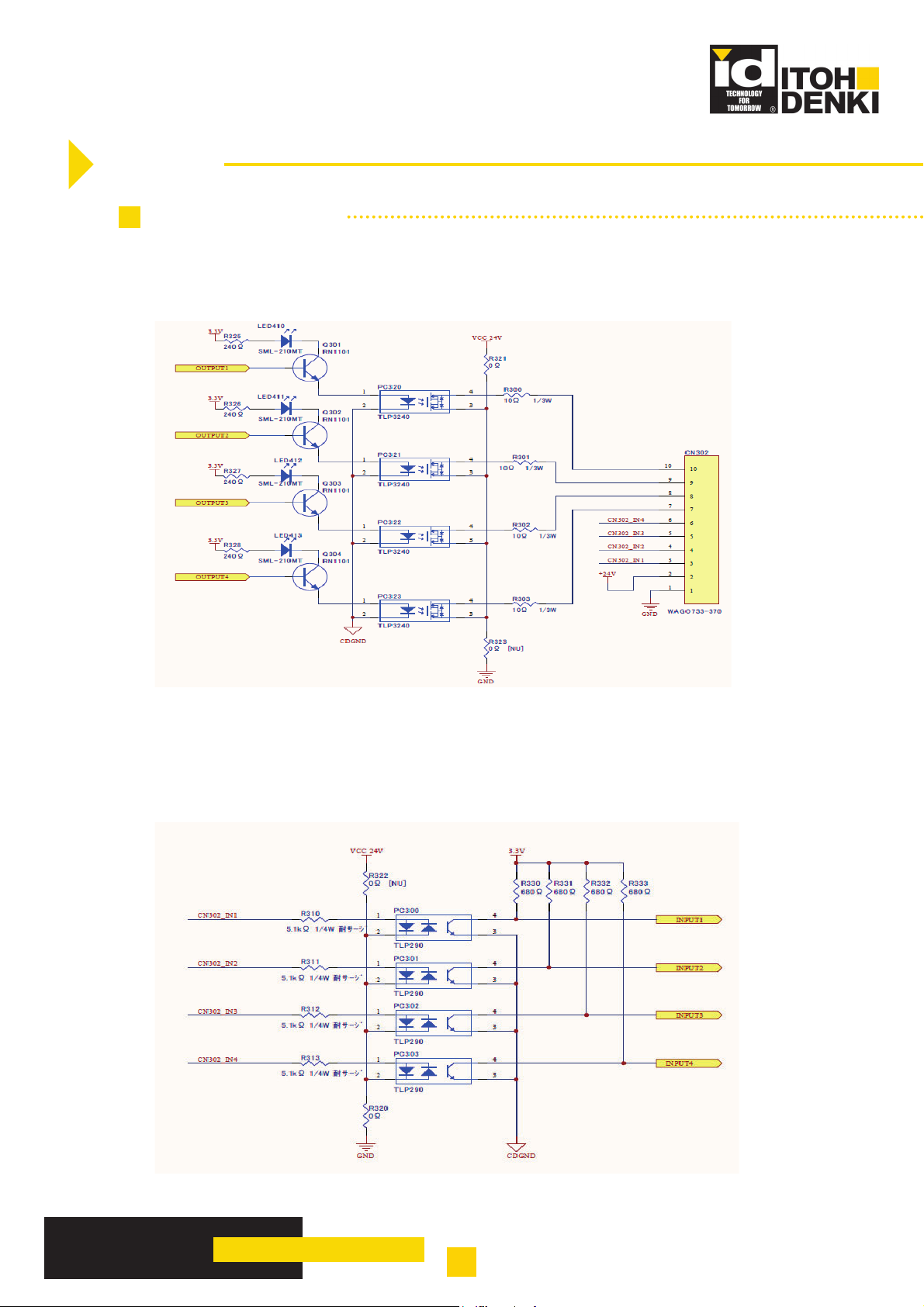
4. WIRING
4.1 - CIRCUIT DIAGRAM
4.1.1 - Remote Output interface circuit
4.1.2 - Remote Input interface circuit
IB-P01
TECHNICAL DOCUMENTATION
7
Original notice - T1.4
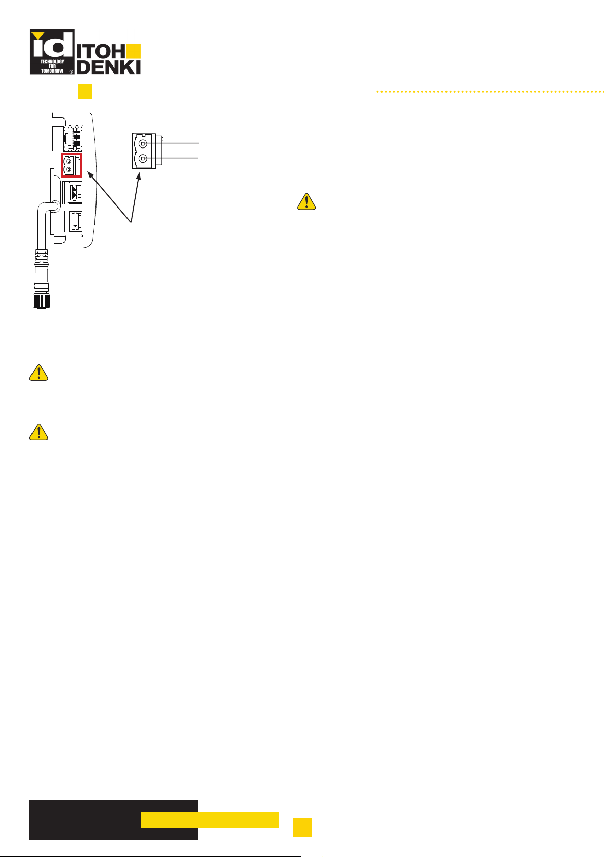
4.2 - CN1 CONNECTOR - 24 VDC POWER SUPPLY
1 - 24 VDC
2 - 0 VDC
• Solid wire or Braided wire
• Minimum cross-section : 2-2.5mm
2
(AWG:14~12)
• The length of stripped wire : 8-9mm
3URYLGHDSRZHUVXSSO\ WKDW LV VXI¿FLHQWO\SRZHUIXO
• (Connecting cable side) WAGO 231-302/026-000
in function of the type and number of motorized rollers to
CN1
be powered.
The stabilized power supplies 24V shall be sized according to the number of motorized rollers that shall work.
It is possible to link some group of motorized rollers to the power supplies. These groups being linked together
thanks to communication cable.
It is mandatory to link the 0v of ALL power supplies together by ensuring that all the 0v terminals are grounded to
the main earth terminal inside the control cabinet. They shall be controlled simoultaneously to avoid creating problem
in transition point.
Make sure that the power supply is turned OFF before plugging / unplugging the motor connector CN101/201.
IB-P01
TECHNICAL DOCUMENTATION
8
Original notice - T1.4

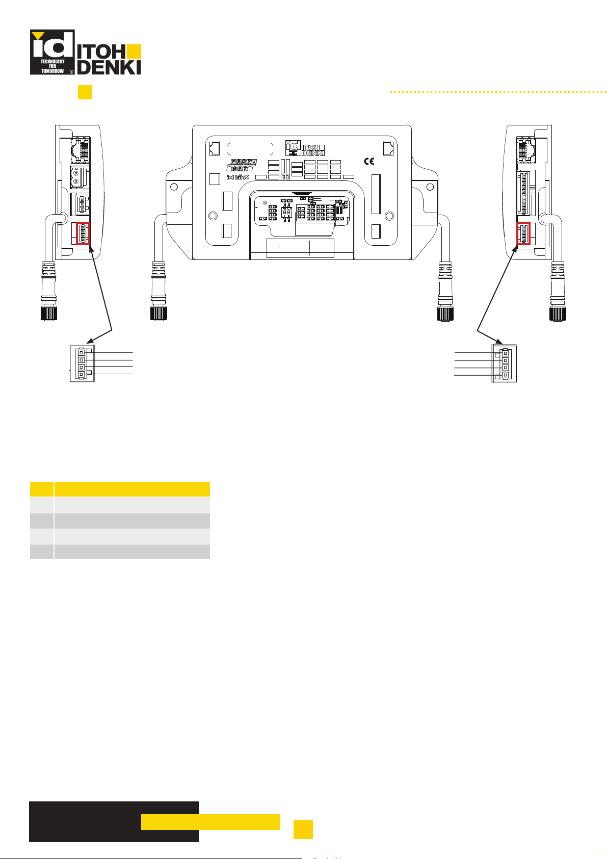
4.3 - CN301 CONNECTOR - CONTROL SUPPLY
3 - FG
2- 0 VDC
1- 24 VDC
CN301
• (Connecting cable side) WAGO 734-103
• Solid wire or Braided wire
• Minimum cross-section : 0.08-1.5mm
• The length of stripped wire : 6-7mm
2
(AWG:28~14)
4.4 - CN302 CONNECTOR - INPUTS / OUTPUTS (I/O)
1
CN302
10
Connector Designation
10V
2 24V
3 INPUT1
4 INPUT2
5 INPUT3
6 INPUT4
7OUTPUT4
8OUTPUT3
9OUTPUT2
10 OUTPUT1
• (Connecting cable side) WAGO 733-110
• Solid wire or Braided wire
• Minimum cross-section : 0.08-0.5mm
• The length of stripped wire : 5-6mm
• Inputs & outputs are PNP only
• Remote Input : 25mA max
• Remote output : 100mA max
2
(AWG:28~20)
IB-P01
TECHNICAL DOCUMENTATION
9
Original notice - T1.4
4.5 - CN305 AND CN304 CONNECTORS - SENSORS
STS B
LAN1
IB-P01F-UL
ACT 2
OUT 1
Motor Power
24V
0V
MOTOR
A
Control Power
FG
0V
24V
Sensor A
ALM
0V
SEN
24V
ACT 1
LAN 1
MOT A
STS A
SEN A
LED400
LED400
LED408
LED408
LED415
LED415
LED406
LED406
LED417
LED417
MAC: 00-22-21-XX-XX-XX
DEVICE: 0x15A001
RIN: 0301 R8C: 51
IN 1
POWER
IN 2
LAN 2
OUT 2
BF
IN 3
MOT B
OUT 3
MB-SYN
MA-SYN
SF
IN 4
R494
R494
R495
R495
R469
R469
34
34
34
2
1
2
1
2
1
LED402
LED402
LED419
LED419
LED403
LED403
LED404
LED421
LED404
LED421
LED405LED420
LED405LED420
SEN B
STS B
OUT 4
R476
R476
R475
R475
R464
R464
RG300
RG300
LED407
LED407
LED410
LED410
LED401
LED401
LED411
LED411
LED409
LED409
LED416
LED412
LED416
LED412
LED41
LED413
LED413
CN304 CN305
Sensor B
IN/OUT
OUT4
OUT3
OUT1
LAN2
0V
24V
IN1
IN2
IN3
IN4
MOTOR
OUT2
B
24V
SEN
0V
ALM
4 - Optional sensor alarm input
3 - 0V
2 - Sensor input
1 - 24 VDC
• (Connecting cable side) WAGO 733-104
• Solid wire or Braided wire
2
• Minimum cross-section : 0.08-0.5mm
(AWG:28~20)
• The length of stripped wire : 5-6mm
N° Designation
1 24VDC
2 Sensor input
30V
4 Optional sensor alarm input
1 - 24 VDC
2 - Sensor input
4 - Optional sensor alarm input
3 - 0V
IB-P01
TECHNICAL DOCUMENTATION
10
Original notice - T1.4

4.6 - CN101 AND CN201 CONNECTORS - MOTOR
STS B
LAN1
IB-P01F-UL
ACT 2
OUT 1
ACT 1
Motor Power
24V
0V
MOTOR
A
Control Power
FG
0V
24V
Sensor A
ALM
0V
SEN
24V
LAN 1
MOT A
STS A
SEN A
LED400
LED400
LED408
LED408
LED415
LED415
LED406
LED406
LED417
LED417
MAC: 00-22-21-XX-XX-XX
DEVICE: 0x15A001
RIN: 0301 R8C: 51
CN101 CN201
IN 1
POWER
IN 2
LAN 2
OUT 2
BF
IN 3
MOT B
MB-SYN
34
34
34
2
2
2
OUT 3
SF
IN 4
R495
R495
R469
R469
LED402
LED402
LED419
LED419
LED403
LED403
LED404
LED421
LED404
LED421
LED405LED420
LED405LED420
SEN B
STS B
OUT 4
R476
R476
R475
R475
R464
R464
RG300
RG300
LED407
LED407
LED410
LED410
LED401
LED401
LED411
LED411
LED409
LED409
LED416
LED412
LED416
LED412
LED41
LED413
LED413
MA-SYN
R494
R494
1
1
1
Sensor B
IN/OUT
OUT4
OUT3
OUT1
LAN2
0V
24V
IN1
IN2
IN3
IN4
MOTOR
OUT2
B
24V
SEN
0V
ALM
4
Black
3
Blue
2
White
1
Brown
N° Color
For the motor output setting
CN101
For the motor port setting
CN201
1 Brown Motor coil U Motor port output (U-phase)
2 White Motor coil V Motor port output (V-phase)
5
Gray
3 Blue Hall sensor signal N/A
4 Black Motor coil W N/A
5 Grey +12VDC N/A
• Switching the motor output setting to motor port output, allows the use of the U and V coil outputs as remote
output.
• “Motor output “and “Motor port” setting are selectable by iCEP or PLC.
Setting method by iCEP: Please refer to «iCEP user» manual.
6HWWLQJPHWKRGE\3/&3OHDVHUHIHUWR©&RQQHFWLRQZLWKWKH3UR¿QHWFDSDEOH3/&ªPDQXDO
7KHRXWSXWVDUH¿[HGWR131
• The maximum output current value is 4 A per motor with IB-P01 circuit board.
The motor port output cannot be changed with NPN open drain output.
IB-P01
TECHNICAL DOCUMENTATION
11
Original notice - T1.4

4.7 - CN401 AND CN402 - RJ45 CONNECTOR
STS B
LAN1
IB-P01F-UL
ACT 2
OUT 1
ACT 1
Motor Power
24V
0V
Control Power
FG
0V
24V
MOTOR
A
Sensor A
ALM
0V
SEN
24V
CN401 CN402
LAN 1
MOT A
STS A
SEN A
LED400
LED400
LED408
LED408
LED415
LED415
LED406
LED406
LED417
LED417
MAC: 00-22-21-XX-XX-XX
DEVICE: 0x15A001
RIN: 0301 R8C: 51
IN 1
POWER
IN 2
LAN 2
OUT 2
BF
IN 3
MOT B
MB-SYN
34
34
34
2
2
2
OUT 3
SF
IN 4
R495
R495
R469
R469
LED402
LED402
LED419
LED419
LED403
LED403
LED404
LED421
LED404
LED421
LED405LED420
LED405LED420
SEN B
STS B
OUT 4
R476
R476
R475
R475
R464
R464
RG300
RG300
LED407
LED407
LED410
LED410
LED401
LED401
LED411
LED411
LED409
LED409
LED416
LED412
LED416
LED412
LED413
LED413
LED41
MA-SYN
R494
R494
1
1
1
N° Designation
1 Tx+ (transmission data +)
2 Tx- (transmission data -)
81
3 Rx+ (reception data +)
4 Not used
5 Not used
6 Rx- (reception data -)
7 Not used
8 Not used
Sensor B
IN/OUT
OUT4
OUT3
OUT1
LAN2
0V
24V
IN1
IN2
IN3
IN4
MOTOR
OUT2
B
24V
SEN
0V
ALM
LAN cable can be either straight through or crossover type cable.
ONLY use PROFINETFHUWL¿HG/$1FDEOHVQRW(WKHUQHWFDEOHV
IB-P01
TECHNICAL DOCUMENTATION
12
Original notice - T1.4

5. SWITCHES CONFIGURATION
5.1 - DIP-SWITCHES CONFIGURATION SW1
STS B
LAN1
IB-P01F-UL
ACT 2
OUT 1
Motor Power
24V
0V
MOTOR
A
Control Power
FG
0V
24V
Sensor A
ALM
0V
SEN
24V
ACT 1
LAN 1
MOT A
STS A
SEN A
LED400
LED400
LED408
LED408
LED415
LED415
LED406
LED406
LED417
LED417
MAC: 00-22-21-XX-XX-XX
DEVICE: 0x15A001
RIN: 0301 R8C: 51
IN 1
POWER
BF
MB-SYN
MA-SYN
SF
R494
R494
R495
R495
34
34
34
2
1
2
1
2
1
LED419
LED419
LED421
LED421
LAN 2
IN 2
OUT 2
IN 3
MOT B
OUT 3
IN 4
R469
R469
LED402
LED402
LED403
LED403
LED404
LED404
LED405LED420
LED405LED420
SEN B
STS B
OUT 4
R476
R476
R475
R475
R464
R464
RG300
RG300
LED407
LED407
LED410
LED410
LED401
LED401
LED411
LED411
LED409
LED409
LED416
LED416
LED412
LED412
LED413
LED413
LED41
SW1
To perform a synchronization of motors, make the settings using these switches.
Sensor B
IN/OUT
OUT4
OUT3
OUT1
LAN2
0V
24V
IN1
IN2
IN3
IN4
MOTOR
OUT2
B
24V
SEN
0V
ALM
SW1-1 SW1-2 Motor A Motor B
OFF OFF Regular operation Regular operation
OFF ON Regular operation Synchronize with Motor A
ON OFF Synchronize with Motor B Regular operation
ON ON Factory reset (see chapter 5.2)
5.2 - FACTORY RESET
To reset the circuit board as factory setting, refer to the bellow procedure:
1 Turn off the power supply to the IB-P01 circuit board.
2 Set the dip switches (SW1 #1 “MA-SYN” and #2 “MB-SYN”) to ON. Set IN1 and IN4 inputs to ON.
3 The initialization will start when the power to the IB-P01 Circuit board is turned on.
4
5 Turn off the power supply to the IB-P01 circuit board.
When the initialization is complete, the LEDs of SenA, SenB, IN1, IN2, IN3, IN4, RUN, SF, and BF
become on.
6
IB-P01
Return the dip switches (SW1 #1 “MA-SYN” and #2 “MB-SYN”) to the state prior to the
initialization.
TECHNICAL DOCUMENTATION
13
Original notice - T1.4

6. WARNING LIGHT LED
R494
R494
LED400
ACT1
LAN1
MOTA
STSA
SENA SENB
LED408
LED408
LED415
LED415
LED406
LED406
LED400
LED417
LED417
1
1
1
R476
R464
R464
LED410
LED410
LED411
LED411
LED412
LED412
LED413
LED413
R476
R475
R475
LED401
LED401
LED409
LED409
LED416
LED416
LED41
LED407
LED407
RG300
RG300
R495
R495
R469
R469
34
34
34
2
2
2
LED402
LED402
LED419
LED419
LED421
LED421
LED403
LED403
LED404
LED404
LED405LED420
LED405LED420
If an error occurs in an IB-P01 circuit
board, it indicates the state of the error in
LED display.
POWER IN2 OUT2 LAN2
BF IN3 OUT3 MOTB
SF IN4 OUT4 STSB
IN1 OUT1 ACT2
LED display error
LED
SENSOR (SEN A/SEN B)
(LED 406 / 407)
Remote IN (IN1~4)
(LED 402 ~ 405)
Remote OUT (OUT1~4)
(LED 410 ~ 413)
POWER (POWER)
(LED 419)
System Fault (SF)
(LED 420)
Bus Fault (BF)
(LED 421)
LINK (LAN1 / LAN2)
(LED 408 / 409)
ACT (ACT1 / ACT2)
(LED 400 / 401)
MOTOR
(MOTA / MOTB / STSA /
STSB)
(LED 415 / 416 / 417 / 418)
Green Red
ON - Sensor input detected
OFF - Sensor input not detected
ON - Remote input detected
OFF - Remote input not detected
ON - Remote output detected
OFF - Remote output not detected
ON - Control power supply ON
Flashing (6Hz) - Power supply of motor power OFF
OFF - Control power supply OFF
- OFF No error
- ON System fault error
- OFF No error
- ON Bus fault error
OFF - Disconnected LAN cable
ON - Connected LAN cable
OFF - No sending/receving data
Flashing - Sending/receving data
OFF OFF Motor stop (No error)
ON OFF
ON Flash (6Hz) Blown fuse
OFF Flash (1Hz) Motor unplugged error
ON Flash (1Hz) Lock error
OFF ON
ON Flash (1.7s 6Hz×2times) Back EMF error
Flash Alternately (1Hz) Flash Alternately (1Hz) JAM error
Flash Alternately (6Hz) Flash Alternately (6Hz) Software error 1
Flash Alternately (2Hz) Flash Alternately (2Hz) Software error 2
LED pattern
Motor or IB-P01 circuit board
*Motor green LED illuminates by any output from UV (W), when motor port is used.
Description
Rotation of a motor
(common to CW and CCW)
Motor port output(*)
thermal error
IB-P01
TECHNICAL DOCUMENTATION
14
Original notice - T1.4

6.1 - LIST OF ERRORS THAT CAN OCCUR IN AN IB-P01 CIRCUIT BOARD
The table shown below summarizes error occurrence conditions and reset conditions for an IB-P01 circuit
board, as well as states of the ladder logic and motor in which an error is occurring. Occurrence of errors
can be checked with iCEP and PLC. Refer to table “LED display error” on Paragraph 6 “PROFINET I/O”, for
information on LED display of errors.
Error type
Motor Power
OFF
Under Voltage
Error
Blown fuse
Motor
Disconnected
Motor Lock 4
PCB Thermal 5
Motor Thermal 6
Back EMF
Error
Motor Port
current limit
Jam Error 8
Soft Error 1 9
Soft Error 2 10
Sensor Alarm 11
Priority
(*1)
1
2
3 Motor disconnected Connect motor Auto/Manu Run Stop
7
Error occurrence
condition
Motor power voltage of
lower than 6 V
Motor power voltage of
6V ~ 15 V
Fuse has been blown on
the motor driver board
Continuously-unchanged
hall signal
Higher than the IB-P01
circuit board temperature
threshold
Higher than the motor
temperature threshold
Continuous back EMF of
40 VDC or higher for 2
seconds
Continuous back EMF of
60 VDC or higher for 0.1
seconds
Continuous motor port
current of 4 A or higher
for 0.1 seconds
Output coils Y7 and Y37
are ON
Output coils Y8 and Y38
are ON
Output coils Y9 and Y39
are ON
Alarm input is ON
(CN304 CN305)
Error reset condition
(*2)
Power supply voltage 18
V or higher
Power supply voltage 18
V or higher
Impossible to reset
Automatic reset: Pulse
change
Reset instruction by upper
level
Manual reset: Reset
instruction by upper level
Lower than the IB-P01
circuit board temperature
threshold
Lower than the motor
temperature threshold
Back EMF of lower than
40 VDC
Motor port current of
lower than 4 A
Output coils Y7 and Y37
are OFF
Output coils Y29 and Y30
are OFF
Output coils Y9 and Y39
are OFF
Sensor alarm input is OFF
(CN304, CN305)
Type of error
reset method
Auto Run Stop
Auto/Manu Run Stop
IB-P01 circuit
board
replacement
Auto/Manu Run Stop
Auto/Manu Run Stop
Auto/Manu Run Stop
Manu Run Stop
Manu Run Stop
Ladder Run Run
Ladder Run Run
Ladder Run Run
Signal input Run Run
Ladder Motor
Run Stop
(*1) If more than one error occurs, the LED display shows the error of the highest priority. If the error of the
highest priority among multiple errors is reset, the errors with the lower priority will be also reset. However, if
thecause of an error remains, the error will be displayed again.
(*2) For manual reset, the error can be reset by the instruction from the higher level, only if the error reset
condition is met. Manual reset is carried out by using iCEP or PLC.
1. Reset by iCEP: Refer to the «iCEP user manual», Chapter 6 Section 2, “Error monitor.”
5HVHWE\3/&5HIHUWR©&RQQHFWLRQZLWKWKH3UR¿QHWFDSDEOH3/&ªPDQXDO3DUDJUDSK³352),1(7,2´
IB-P01
TECHNICAL DOCUMENTATION
15
Original notice - T1.4
7. TECHNICAL DATAS ACCORDING MOTORIZED ROLLER
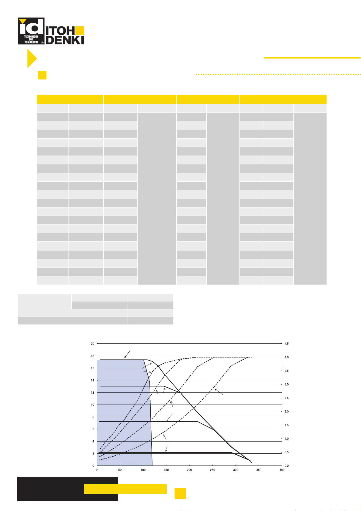
7.1 - WITH PM500VE MOTORIZED ROLLER
PM500VE - SPEED CODE 17
V (m/min)+/-3% Tangential force (N) Torque (Nm) Current (A)
No load Nominal Nominal Start-up Nominal Start-up No load Nominal Start-up
17.4 17.4 101.1
15.9 15.9 106.4 2,6 0,6 2,7
15.2 15.2 108.9 2,7 0,6 2,7
14.5 14.5 111.7 2,8 0,5 2,7
13.7 13.7 114.2 2,9 0,5 2,7
13.0 13.0 114.5 2,9 0,5 2,6
11.6 11.6 115.2 2,9 0,4 2,4
10.9 10.9 115.5 2,9 0,4 2,3
10.1 10.1 115.5 3,0 0,4 2,2
9.4 9.4 115.8 3,0 0,4 2,1
8.7 8.7 116.1 3,0 0,4 2.0
335
8.0 8.0 116.4 3,0 0,3 1,9
7.2 7.2 116.7 3,0 0,3 1,7
6.5 6.5 117.0 3,0 0,3 1,6
5.8 5.8 117.4 3,0 0,3 1,5
5.1 5.1 117.7 3,0 0,3 1,4
4.3 4.3 118.0 3,0 0,3 1,3
3.6 3.6 118.3 3,0 0,2 1,2
2.9 2.9 118.6 3,0 0,2 1,1
2.2 2.2 118.9 3,0 0,2 1,0
2,5
8.4
0,7 2,8
4,0
Servo brake
Tangential force 5.0~102N
Absorbed current 0,1~1,0A max
Reduction ratio 1/44,95
Stage 3 stage
Speed
(m/min)
Area of continuous
operation
Speed vs Tangential force
17.4 m/min
13.0 m/min
7,2 m/min
2.2 m/min
Current vs Tangential force
Current(A) Current(A) Current(A)
Current (A)
IB-P01
TECHNICAL DOCUMENTATION
Tangential force (N)
16
Original notice - T1.4

PM500VE - SPEED CODE 25
/
V (m/min)+/-3% Tangential force (N) Torque (Nm) Current (A)
No load Nominal Nominal Start-up Nominal Start-up No load Nominal Start-up
29.1 29.1 68.1
26.7 26.7 71.7 1.8 0.6 2.7
25.4 25.4 73.4 1.8 0.6 2.7
24.2 24.2 75.3 1.9 0.5 2.7
23.0 23.0 77.0 1.9 0.5 2.7
21.8 21.8 77.2 1.9 0.5 2.6
19.4 19.4 77.6 1.9 0.4 2.4
18.2 18.2 77.8 2.0 0.4 2.3
17.0 17.0 77.8 2.0 0.4 2.2
15.7 15.7 78.1 2.0 0.4 2.1
14.5 14.5 78.3 2.0 0.4 2.0
226
13.3 13.3 78.5 2.0 0.3 1.9
12.1 12.1 78.7 2.0 0.3 1.7
10.9 10.9 78.9 2.0 0.3 1.6
9.7 9.7 79.1 2.0 0.3 1.5
8.5 8.5 79.3 2.0 0.3 1.4
7.3 7.3 79.5 2.0 0.3 1.3
6.1 6.1 79.7 2.0 0.2 1.2
4.8 4.8 80.0 2.0 0.2 1.1
3.6 3.6 80.2 2.0 0.2 1.0
1.7
5.7
0.7 2.8
4.0
Servo brake
Tangential force 5.0~78.0N
Absorbed current 0,1~1,0A max
Reduction ratio 1/26,67
Stage 2 stage
Speed
(m/min)
Speed vs Tangential force
29.1 m/min
Area of continuous
operation
21.8 m/min
12.2 m/min
3.6 m/min
Current vs Tangential force
Current (A)
Tangential force (N)
IB-P01
TECHNICAL DOCUMENTATION
17
Original notice - T1.4

PM500VE - SPEED CODE 60
/
V (m/min)+/-3% Tangential force (N) Torque (Nm) Current (A)
No load Nominal Nominal Start-up Nominal Start-up No load Nominal Start-up
61.7 61.5 32.3
56.6 56.6 34.0 0.8 0.6 2.7
54.0 54.0 34.8 0.8 0.6 2.7
51.4 51.4 35.7 0.9 0.5 2.7
48.9 48.9 36.5 0.9 0.5 2.7
46.3 46.3 36.6 0.9 0.5 2.6
41.1 41.2 36.8 0.9 0.4 2.4
38.6 38.6 36.9 0.9 0.4 2.3
36.0 36.0 36.9 0.9 0.4 2.2
33.4 33.4 37.0 0.9 0.4 2.1
30.9 30.9 37.1 0.9 0.4 2.0
107
28.3 28.3 37.2 0.9 0.3 1.9
25.7 25.7 37.3 0.9 0.3 1.7
23.1 23.1 37.4 0.9 0.3 1.6
20.6 20.6 37.5 0.9 0.3 1.5
18.0 18.0 37.6 0.9 0.3 1.4
15.4 15.4 37.7 0.9 0.3 1.3
12.9 12.9 37.8 0.9 0.2 1.2
10.3 10.3 37.9 0.9 0.2 1.1
7.7 7.7 38.0 0.9 0.2 1.0
0.8
2.7
0.7 2.8
4.0
Servo brake
Tangential force 4.5~42.0N
Absorbed current 0,1~1,0A max
Reduction ratio 1/12,64
Stage 2 stage
Speed
(m/min)
Area of continuous
operation
Speed vs Tangential force
61.7 m/min
1
46.3 m/min
25.7 m/min
7.7 m/min
Current vs Tangential force
Current (A)
Tangential force (N)
IB-P01
TECHNICAL DOCUMENTATION
18
Original notice - T1.4

PM500VE - SPEED CODE 90
/
V (m/min)+/-3% Tangential force (N) Torque (Nm) Current (A)
No load Nominal Nominal Start-up Nominal Start-up No load Nominal Start-up
104.0 104.0 21.8
95.4 95.4 22.9 0.6 0.6 2.7
91.0 91.0 23.5 0.6 0.6 2.7
86.6 86.6 24.1 0.6 0.5 2.7
82.4 82.4 24.6 0.6 0.5 2.7
78.0 78.0 24.7 0.6 0.5 2.6
69.4 69.4 24.8 0.6 0.4 2.4
65.1 65.1 24.9 0.6 0.4 2.3
60.7 60.7 24.9 0.6 0.4 2.2
56.3 56.3 24.9 0.6 0.4 2.1
52.1 52.1 25.0 0.6 0.4 2.0
72
47.7 47.7 25.1 0.6 0.3 1.9
43.3 43.3 25.2 0.6 0.3 1.7
38.9 38.9 25.2 0.6 0.3 1.6
34.7 34.7 25.3 0.6 0.3 1.5
30.3 30.3 25.4 0.6 0.3 1.4
26.0 26.0 25.4 0.6 0.3 1.3
21.7 21.7 25.5 0.6 0.2 1.2
17.4 17.4 25.6 0.6 0.2 1.1
13.0 13.0 25.6 0.6 0.2 1.0
0.6
1.8
0.7 2.8
4.0
Servo brake
Tangential force 4.0~33.0N
Absorbed current 0,1~1,0A max
Reduction ratio 1/7,5
Stage 1 stage
Speed
(m/min)
Area of continuous
Speed vs Tangential force
104.0 m/min
operation
78.0 m/min
43.3 m/min
13.0 m/min
Current vs Tangential force
Current (A)
Tangential force (N)
IB-P01
TECHNICAL DOCUMENTATION
19
Original notice - T1.4

7.2 - WITH PM605VE MOTORIZED ROLLER
PM605VE - SPEED CODE 17
V (m/min)+/-3% Tangential force (N) Torque (Nm) Current (A)
No load Nominal Nominal Starting Nominal Starting No load Nominal Starting
21,1 21,1 83,6
19,2 19,2 87,9 2,6 0,6 2,7
18,4 18,4 90,0 2,7 0,6 2,7
17,5 17,5 92,3 2,8 0,5 2,7
16,6 16,6 94,4 2,9 0,5 2,7
15,7 15,7 94,6 2,9 0,5 2,6
14,0 14,0 95,2 2,9 0,4 2,4
13,2 13,2 95,5 2,9 0,4 2,3
12,2 12,2 95,5 3,0 0,4 2,2
11,4 11,4 95,7 3,0 0,4 2,1
10,5 10,5 96,0 3,0 0,4 2,0
9,7 9,7 96,2 3,0 0,3 1,9
8,7 8,7 96,4 3,0 0,3 1,7
7,9 7,9 96,7 3,0 0,3 1,6
7,0 7,0 97,0 3,0 0,3 1,5
6,2 6,2 97,3 3,0 0,3 1,4
5,2 5,2 97,5 3,0 0,3 1,3
4,4 4,4 97,8 3,0 0,2 1,2
3,5 3,5 98,0 3,0 0,2 1,1
2,7 2,7 98,3 3,0 0,2 1
277
2,5
8.4
0,7 2,8
4,0
Servo brake
Tangential force 4.1~84.3N
Absorbed current 0,1~1,0A max
Reduction ratio 1/44,95
Stage 3 stage
PM605VE - SPEED CODE 25
V (m/min)+/-3% Tangential force (N) Torque (Nm) Current (A)
No load Nominal Nominal Starting Nominal Starting No load Nominal Starting
35,2 35,2 56,3
32,3 32,3 59,3 1,8 0,6 2,7
30,7 30,7 60,7 1,8 0,6 2,7
29,3 29,3 62,2 1,9 0,5 2,7
27,8 27,8 63,6 1,9 0,5 2,7
26,4 26,4 63,8 1,9 0,5 2,6
23,5 23,5 64,1 1,9 0,4 2,4
22,0 22,0 64,3 2,0 0,4 2,3
20,6 20,6 64,3 2,0 0,4 2,2
19,0 19,0 64,5 2,0 0,4 2,1
17,5 17,5 64,7 2,0 0,4 2,0
16,1 16,1 64,9 2,0 0,3 1,9
14,6 14,6 65,0 2,0 0,3 1,7
13,2 13,2 65,2 2,0 0,3 1,6
11,7 11,7 65,4 2,0 0,3 1,5
10,3 10,3 65,5 2,0 0,3 1,4
8,8 8,8 65,7 2,0 0,3 1,3
7,4 7,4 65,9 2,0 0,2 1,2
5,8 5,8 66,1 2,0 0,2 1,1
4,4 4,4 66,3 2,0 0,2 1
187
1,7
5.7
0,7 2,8
4.0
Servo brake
Tangential force 4.1~64.5N
Absorbed current 0,1~1,0A max
Reduction ratio 1/26,67
Stage 2 stage
IB-P01
TECHNICAL DOCUMENTATION
20
Original notice - T1.4

PM605VE - SPEED CODE 60
V (m/min)+/-3% Tangential force (N) Torque (Nm) Current (A)
No load Nominal Nominal Starting Nominal Starting No load Nominal Starting
74,7 74,9 26,7
68,5 68,5 28,1 0,8 0,6 2,7
65,3 65,3 28,8 0,8 0,6 2,7
62,2 62,2 29,5 0,9 0,5 2,7
59,2 59,2 30,2 0,9 0,5 2,7
56,0 56,0 30,2 0,9 0,5 2,6
49,7 49,9 30,4 0,9 0,4 2,4
46,7 46,7 30,5 0,9 0,4 2,3
43,6 43,6 30,5 0,9 0,4 2,2
40,4 40,4 30,6 0,9 0,4 2,1
37,4 37,4 30,7 0,9 0,4 2,0
34,2 34,2 30,7 0,9 0,3 1,9
31,1 31,1 30,8 0,9 0,3 1,7
28,0 28,0 30,9 0,9 0,3 1,6
24,9 24,9 31,0 0,9 0,3 1,5
21,8 21,8 31,1 0,9 0,3 1,4
18,6 18,6 31,2 0,9 0,3 1,3
15,6 15,6 31,2 0,9 0,2 1,2
12,5 12,5 31,3 0,9 0,2 1,1
9,3 9,3 31,4 0,9 0,2 1
88
0,8
2.7
0,7 2,8
4.0
Servo brake
Tangential force 3.7~34.7N
Absorbed current 0,1~1,0A max
Reduction ratio 1/12,64
Stage 2 stage
PM605VE - SPEED CODE 90
V (m/min)+/-3% Tangential force (N) Torque (Nm) Current (A)
No load Nominal Nominal Starting Nominal Starting No load Nominal Starting
125,8 125,8 18,0
115,4 115,4 18,9 0,6 0,6 2,7
110,1 110,1 19,4 0,6 0,6 2,7
104,8 104,8 19,9 0,6 0,5 2,7
99,7 99,7 20,3 0,6 0,5 2,7
94,4 94,4 20,4 0,6 0,5 2,6
84,0 84,0 20,5 0,6 0,4 2,4
78,8 78,8 20,6 0,6 0,4 2,3
73,4 73,4 20,6 0,6 0,4 2,2
68,1 68,1 20,6 0,6 0,4 2,1
63,0 63,0 20,7 0,6 0,4 2,0
57,7 57,7 20,7 0,6 0,3 1,9
52,4 52,4 20,8 0,6 0,3 1,7
47,1 47,1 20,8 0,6 0,3 1,6
42,0 42,0 20,9 0,6 0,3 1,5
36,7 36,7 21,0 0,6 0,3 1,4
31,5 31,5 21,0 0,6 0,3 1,3
26,3 26,3 21,1 0,6 0,2 1,2
21,1 21,1 21,2 0,6 0,2 1,1
15,7 15,7 21,2 0,6 0,2 1
60
0,6
1.8
0,7 2,8
4.0
Servo brake
Absorbed current 0,1~1,0A max
Reduction ratio 1/7,5
Stage 1 stage
Tangential force 3.3~27.3N
IB-P01
TECHNICAL DOCUMENTATION
21
Original notice - T1.4

8. NETWORK CONFIGURATION
To use iCEP, you need to connect the PC and IB-P01 circuit boards.
8VHWKH¿JXUHVVKRZQEHORZIRU\RXUUHIHUHQFHZKHQZLULQJ,%3FLUFXLWERDUGV<RXFDQXVHHLWKHUVWUDLJKW
through or crossover cables as a LAN cable used between IB-P01 circuit boards.
For further information refer to iCEP user manual.
8.1 - CASCADE CONNECTION
iCEP (PC application)
PROFINET
IB-P01 IB-P01 IB-P01 IB-P01
192.168.1.1
192.168.1.2
192.168.1.3
8.2 - STAR CONNECTION
iCEP (PC application)
Hub
IB-P01 IB-P01 IB-P01 IB-P01
192.168.1.4
IB-P01
192.168.1.1
TECHNICAL DOCUMENTATION
192.168.1.2
22
192.168.1.3
192.168.1.4
Original notice - T1.4

9. CONTROLLING IB-P01 CIRCUIT BOARD
,%FLUFXLWERDUGVFDQEHFRQ¿JXUHGLQHLWKHUDV0$67(5RU6/$9(PRGHV,IDQ,%3FLUFXLWERDUGLVVHWWR
a master, the motor RUN and remote output on the board can be controlled by its own board. If IB-P01 circuit
boards are set to slaves, the motor RUN and remote output on each IB-P01 circuit board cannot be controlled
by its own board, and they will be controlled by the master. For further information refer to iCEP user manual.
This section introduces four typical or example usages as follows:
9.1 - WHEN THE PROFINET CAPABLE PLC CONTROLS IB-P01 CIRCUIT BOARD
Set the PLC to be the master and IB-P01 circuit boards to be slaves to make a PROFINET I/O between the PLC
and IB-P01 circuit boards. The PLC will control all the IB-P01 circuit boards.
PROFINET capable PLC
PROFINET I/O (obtaining sensor and error information)
Motor RUN
instruction, etc...
IB-P01 (Slave) IB-P01 (Slave) IB-P01 (Slave) IB-P01 (Slave)
Ladder N/A
Ladder N/A
Ladder N/A
Ladder N/A
9.2 - IN CASE OF CONTROLLING THE LOCAL ‘OWN’ ZONE BY IB-P01 CIRCUIT BOARD, AND
MONITORING EACH ZONE BY PROFINET CAPABLE PLC
Set each IB-P01 circuit board as a master, and download ladder logic onto each of them. Each IB-P01 circuit
board controls its own zone. The PLC monitors the status of each PROFINET I/O zone. In this case, it is possible
to write data from the PLC into the data register of each IB-P01 circuit board.
PROFINET capable PLC
PROFINET I/O (obtaining sensor and error information)
PROFINET I/O
Writing data into the
data registrer
Communication
between boards
(sensor information,
etc...)
IB-P01
IB-P01 (Master) IB-P01 (Master) IB-P01 (Master) IB-P01 (Master)
With ladder
TECHNICAL DOCUMENTATION
With ladder
23
With ladder
With ladder
Original notice - T1.4

9.3 - WHEN THE NETWORK IS CONFIGURED ONLY WITH IB-P01 CIRCUIT BOARD
Set each IB-P01 circuit board as a master, and download ladder logic onto each of them. Each IB-P01 circuit
board controls its own zone. The control can be performed without connecting the PC or PLC.
Communication between boards
(sensor information, etc...)
IB-P01 (Master) IB-P01 (Master) IB-P01 (Master) IB-P01 (Master)
With ladder
With ladder
With ladder
With ladder
9.4 - WHEN ONE IB-P01 CIRCUIT BOARD CONTROLS MULTIPLE CONNECTED
IB-P01
Download ladder logic onto the master IB-P01 circuit board. Set other IB-P01 circuit boards as slaves. The
master IB-P01 circuit board controls its own zone and the zones of the slaves. Up to seven slave IB-P01 circuit
boards can be controlled by one master IB-P01 circuit board.
With ladder
IB-P01 (Master)
Communication
between boards
(motor RUN instruction)
CIRCUIT BOARD
Communication between boards
(sensor information, etc...)
IB-P01
IB-P01 (Slave) IB-P01 (Slave) IB-P01 (Slave) IB-P01 (Slave)
Ladder N/A
Ladder N/A
Ladder N/A
Ladder N/A
Up to 7 IB-P01 circuit boards
TECHNICAL DOCUMENTATION
24
Original notice - T1.4

ANNEX 1
AKASHI, G
to
INCORPORATION DECLARATION
ACCORDANCE WITH THE EC MACHINERY DIRECTIVE 2006/42/EC, ANNEX II B
IN
The manufacturer :
ITOH DENKI CO., Ltd
1146-2 Asazuma-Cho, Kasai, Hyogo 679-0105 Japan
Distributed in Europe by :
ITOH DENKI Europe SAS
490 avenue des Jourdies - PAE les Jourdies - BP 323
74807 St Pierre en Faucigny Cedex - France
hereby declares that the product series:
IB-P01
LVDQLQFRPSOHWHPDFKLQHDVGH¿QHGLQWKH(&0DFKLQHU\'LUHFWLYHDQGWKHUHIRUHGRHVQRWIXOO\PHHW
WKHUHTXLUHPHQWVRIWKLV'LUHFWLYH6HUYLFHHQWU\LVSURKLELWHGXQWLOWKHZKROHPDFKLQHV\VWHPLQZKLFK
LWLVLQFRUSRUDWHGLVGHFODUHGWREHLQFRPSOLDQFHZLWKWKH(&0DFKLQHU\'LUHFWLYH
The health and safety requirements of Annex I have been applied. The special technical documents in
accordance with Annex VII have been drawn up (and, if appropriate, submitted to the competent authorities).
Person authorized to compile the technical documentation :
ITOH DENKI CO., Ltd
Toshiyuki TACHIBANA
1146-2 Asazuma-Cho, Kasai, Hyogo 679-0105 Japan
ITOH DENKI EUROPE SAS
Makoto MITSUYOSHI
490 Avenue des Jourdies, 74800 St Pierre en Faucigny - France
(&'LUHFWLYHVDSSOLHG
• Machinery Directive 2006/42/EC
• European EMC Directive 2014/30/EC
• European RoHS Directive 2011/65/EU
CIRCUIT BOARD
ITOH DENKI EUROPE SAS, undertakes to forward, following a duly motivated request from the national
authorities, the relevant information concerning the quasi-machine.
Saint Pierre en Faucigny, 15 December 2017
T. AKASHI, General Director
.
eneral Direc
IB-P01
TECHNICAL DOCUMENTATION
25
Original notice - T1.4

,72+'(1.,(8523(6$6
UK BRANCH OFFICE
GERMAN BRANCH OFFICE
490 Av. des Jourdies
P.A.E. les Jourdies
74800 St Pierre en Faucigny - France
Tél. : +33 (0)4 50 03 09 99
Fax : +33 (0)4 50 03 07 60
E-mail : info@itoh-denki.com
Suite 1 Trinity Space Centre
Waldorf Way
:DNH¿HOG:)'+8.
Tel : +44 (0)1924 366 539
Fax : +33 (0)4 50 03 07 60
E-mail : info@itoh-denki.com
:::,72+'(1.,&20
26
Lebacher Strasse 4
66113 Saarbrücken - Deutschland
Tel : +49 911 25 26 - 200
Fax : +49 911 25 26 - 201
E-mail : info@itoh-denki.de
 Loading...