


Bluetooth Door Access Controller
User Manual
(Please read carefully before using the device)
Product model: ITL-6MJ-B
Revision date: Sept.29,2016
Chapter 1 Product Profile
1.1 Brief Introduction
The device utilizes Bluetooth 4.0(BLE). Blutooth data
communicates with mobile APP to realize the function of
controlling the door access contro device.
Figure 1.1 Appearance Drawing
(Only for reference)
1.2 Technical Parameter
Power Supply DC10~15V,Working Current <100mA,
(Do not include the current driving the electric lock.)
Working Temperature: -10~60℃.
Relative humidity: 20%~90% no condensation.
Storage Temperature: -20--70℃.

Relative humidity: 20%~90% no condensation.
Applicable System: Android4.3+, IOS7.0+.
Communication Distance:0~10M.
(Deviation will be exist in different environment)
Response Time: For IOS 0~3S;For Android:Due to
the variety of equipment, there are differences in
different mobile phones, there is no uniform standard.
Dimension: L72*W49.5*H17mm.
Chapter 2 Introduction of Hardware
2.1 P1—Power Input Port
The port has polarity reverse connection protection and
short-circuit protection. As explained below:
P1
Description
1 (Yellow)
NO: Spare switch output
2 (Blue)
COM: Spare switch output
3 (Black)
GND: Power input negative pole
4 (Red)
12V: Power input positive pole
Note: The wrong power supply connection may cause
damage to the protective device.
2.2 P2— Electric lock control and input
detection port
The port is used for electric lock controller and input
detection:

P2
Description
1 (White)
LOCKB:Electric lock control signal
(switch) output
2 (White)
LOCKA:Electric lock control signal
(switch) output
3 (Gray)
BUT:Exit button Input
4 (Black)
GND:Ground
5 (Orange)
PST: Door magnetic detection
6 (Black)
GND:Ground
Connection instructions:
Door access control device connected with heavy
current electric lock (suitable for pulse electric lock):
Cut off PST and GND, for JP1,select NO-COM
Door access control device connected with low
current electric lock (Electric/magnetic lockect,ect.):
(1) Power-off unlocked: JP1,select NO-COM.
(2) Power-on unlocked:JP1, select NC-COM.
Door access control device connected with exit button:
BUT and GND connect with the button.
2.3 JP1—Normal open/close switch jumper
For selecting the character of the swich Signal (LOCKA,
LOCKB enabling signal) outputting by the door access
controller.
Note: The type of the access control electric lock should
be set by the debugging APP.
If the electric lock is set as heavy current electric lock
(pulse electric lock), the signal outputting by LOCKA

and LOCKB as below:
JP1
Power
Off
Power
On
Status after
App opening
the door
NO-COM
Output
opencircuit
signal
Output
opencircuit
signa
Recovery after
closing 0.2S
NC-COM
Output
closed
signal
Output
closed
signal
Recovery after
opening 0.2S
Note: For the electric lock which unlocked by closure,
to prevent burning the lock , it is strongly recommended
that do not use NC-COM to short circuit.
If the electric lock is set as low current electric lock
(Electric/magnetic lockect),the signal outputting by
LOCKA and LOCKB as below:
JP1
Power
Off
Power
On
Status after
App opening
the door
NO-COM
Output
opencircuit
signal
Output
closed
signal
Recovery after
opening a while
NC-COM
Output
closed
signal
Output
opencircuit
signal
Recovery after
closing a while
Instructions: If the electric lock is the low current
electric lock (Electric/magnetic lockect),magnetic signal
will be detected when the door access controller is power

on (If PST and GND are not closed, LOCKA and
LOCKB status would be the same as the status when
power off . Only close the PST and GND, the LOCKA
and LOCKB output will be contrary to the output when it
is power off).
Magnetic signal will also be detected when unlock the
door by using APP: if the magnetic is not closed, the
unlock signal will be output all the time when opening
the door by APP. Only close the magnetic , the lock will
be locked.
Note: Because of the various electric locks, high voltage
pulses generated from the power supply when open or
close the electric lock are also different. It is strongly
suggested that the separated power supply should be used
for the electric lock and door access sensor!
2.4 JP2—Initialization jumper
The initialization operation will clear or restore the
following information to the default state:key and the
project information, machine number,lock type, and
unlock delaying time.
Specific operation: JP2 shorted for a while (more than
hundreds milliseconds), then cut off it, the buzzer will
bleep once, it stands for initializing successfully.
Note: JP2 must be cut off after finishing initialization!
2.5 LED—Indicator light instruction
LED indicator light is the status indicator light, specific
instruction as below:
LED
Status Instruction
Flash quickly
(100ms/times)
Unauthorized device
or abnormal device
Flash slowly
(1S/times)
Work normally
Always light,
no flash(0~3S)
App is being operated
Chapter 3 User APP Instruction
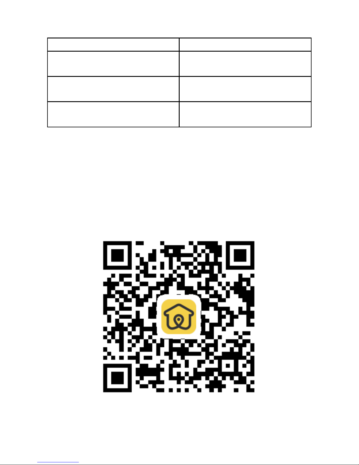
BLE 4.0 is applied for the Bluetooth door access
controller. It is suitable for the smartphone system
version: Android4.3+ ,IOS7.0+. Please download the
APP that work with the device via scan the following QR
code or APP store by searching “Jia-R”.
Figure 3.1 Jia-R QR Code

Chapter 4 Operation instruction
After installation, power on the device, then initialize the
device, set the machine number and lock type, download
the corresponding parameters.
Device authorization and setting of operating
parameters
First use or after initialization, the corresponding
parameters should be set via debug APP before working.
Technical support will be provided by ITLONG.
Parameters as below:
Key and project informations: the key for certificating
and project informations which be used when the door
access controller works.
Machine number: it is the same as the number of the
device which corresponding to the user’s APP. The
default machine number is 0.
Lock type: Electric lock and downward mortise lock
(including electric downward mortise lock , magnetic
lock). Lock type settings need to be consistent with the
lock on the site. The default lock type is electric lock.
Opening delay:Output the open signal duration.The
default opening delay is 5S.
Note: Initialization will clear the above parameters, the
device will restore to the default factory state.
Download and Register APP
After finishing the download, open the APP to
register.Registration requires the mobile phone number

and SMS verification. It is recommended that users use
the current phone number to register.
Administrator issues authorization
For the registered users, the authorized devices will be
displayed after the administrator issuing the authorization
in the background management center and synchronizing
user authorization informations to the mobile terminal
through the cloud. If the authorized device is not
displayed after issuing the authorization ,please sign out
and try to sign in again.
User Access
Support 3 methods to access: Manual click,Sense
automatically,Shake mobile. Sign in the APP, then enter
Door Open Setting to choose or modify the method.
Manual Click: The words of the available device
name will become black color when the user closes to
the device and the device is detected by the APP. Then
click the available device icon, the door will be
opened after the device checking the authorization.
Sense automatically: If the user selects sense
automatically mode, the APP would issue a command
of opening the door automatically when detced the
available device.
Note: Every time when the users enter into the detection
zone, the door will be opened automatically for one time.
If the users need to open again, please click the device
icon or shake the mobile.
Shake mobile: The mode is familiar with the manual
click. Just the Trigger mode is changed from click to

shake.
Chapter 5 Installation and Debugging
5.1 Attention
Please do remark when threading cable must be put in
the joint of terminal box, if ignore this aspect,it may
cause some troubles for installation,debugging.
In the same system, all the wires must be the same
type.
Please Note that the access control device can not be
installed in the metal surface, because the metal
surface and confined environment will interfere with
the Bluetooth.
The connection of the controller and electric lock:
using 4-core power cord (named as electric lock and
magnetic cable). If the electric lock do not have
magnetic signal wire, the 2-core power cord could be
used, the diameter of it should be equal or more than
0.5mm2 , RVV2*0.5mm
2.
If the electric lock and
magnetic cable and the access control device cable in
the same pipe, 4-core shielded wire should be used,
RVVP4*0.5mm2 .
The connection of the controller and exit button:
using 2-core power cord, the diameter of it should be
equal or more than 0.5mm2 , RVV2*0.5mm2.
The connection of the controller and power supply:
the diameter of the cord should be equal or more than
0.75mm2, RVV2*0.75mm2.
Please strictly abide by the above instructions when

cabling and designing the location for the device. If
not, there will be explicit or implicit errors, even
inexplicable errors, until then, there will be no way to
solve it except rework.
5.2 Device installation location
The device can be installed in the exposed position, it
can also be concealed installation. It depends on the
construction site and customer requirements. It is
strongly recommended to install close to the gate.
Exit button installation location:The button should be
installed indoors. The height is depended on the
customer requirements.
The electric lock location: electric control lock catch
and electric clamp lock should be installed on the side
of the door frame ; magnetic lock and electric bolt
lock should be installed at the top of the door frame ;
shear lock should be installed at the bottom of the
door frame.
Power supply installation location: The device uses
specialized power supply,the power supply is
generally installed in the indoor ceiling or weak wells.
5.3 Connection and debugging
Machine number setting.
Note: the machine numbers of the devices can not be
repeated.
Choose the jumper to set the electric lock drive mode
(normal open,normal close).The jumper is determined
by the power supply mode of the electric lock.
When the power is on, if the indicator light (red light)

flash quickly (once every 100ms), the device can
work only after being authorized by the management
APP, and the indicator light will flash slowly (once a
second).
Open the door via APP, the buzzer bleep once,and the
door will be open. If the buzzer bleep several times, it
indicates that the APP authorization is wrong.
Open the door via exit button, the door would be
closed automatically a few moments later.
Chapter 6 Common trouble shooting
Here are some common faults and simple ways to check
them.Please cut off the power while conducting operation
on hardware device.
Common Fault 1: App can not search the device
normally.
Possible Causes and solutions:
First please confirm that the device whether is
authorized.If not, the indicator light will flash quickly.
Solution: Issue the authorization via debugging APP.
The phone systm version is too low, the compatibility
with Bluetooth 4.0 is poor.
Solution: Change a phone to try again.
Bluetooth signals are interfered or blocked by the
environment.
Solution: Replace the device installation location or
close to the device to search the device

Common Fault 2:Fail to open the door via manual
click
Possible Causes and solutions:
Unauthorized device
Solution: please confirm to click the current device
The device is not in the available detection zone (the
words color is gray).
Solution: Please close to the device. If the device is
detected, the words color will become black.
The phone systm version is too low, the compatibility
with Bluetooth 4.0 is poor.
Solution: Change the phone to try again.
Other solution: reboot the phone
Chapter 7 Regulatory
Note:This equipment has been tested and found to
comply with the limits for a Class B digital device,
pursuant to part 15 of the FCC Rules. These limits
aredesigned to provide reasonable protection against
harmful interference in a residential installation. This
equipment generates uses and can radiate radio frequency
energy and, if not installed and used in accordance with
the instructions, may cause harmful interference to radio
communications. However, there is no guarantee that
interference will not occur in a particular installation. If
this equipment does cause harmful interference to radio
or television reception, which can be determined by
turning the equipment off and on, the user is encouraged
to try to correct the interference by one or more of the

following measures:
Reorient or relocate the receiving antenna.
Increase the separation between the equipment and
receiver.
Connect the equipment into an outlet on a circuit
different from that to which the receiver is connected.
Consult the dealer or an experienced radio/TV
technician for help
Caution:Changes or modifications not expressly
approved by the party responsible for compliance could
void the user's authority to operate the equipment.
Warning:This device complies with Part 15 of the FCC
Rules. Operation is subject to the following two
conditions: (1) this device may not cause harmful
interference, and(2) this device must accept any
interference received, including interference that may
cause undesired operation.
 Loading...