

ITI Simon Owner's Manual

S I M O N O W N E R ' S M A N U A L
FCC Notices
FCC Part 15 Information to the User
Changes or modification s not expressly approved by Interlogix Inc . can void the user’s authority to operate the equipment.
FCC Part 15 Class B
This equipment has been tested a nd found to comply with the limits for a Class B digit al device, pursuant to part 15 of the FCC Rules. These limits are
designed to provide reasona ble prot ection against interference in a residential installation.
This equipment generates, uses, and can radia te radio frequency ene rgy and, if not installed and used in ac cordance with the instructions, may cause harmful
interference to radio comm unications. However, there is no guarante e tha t in te rfe rence will not occur in a particul ar installation.
If this equipment does cause harm ful interference to radio or tel evision reception, which can be de t erm i ned by turning the equipment off and on , the user is
encouraged to try to corre ct the interference by on e or m ore of the following meas ure s :
• Reorient or relocate the receiving antenna.
• Increase the separation between the equipment and receiver.
• Connect the affected equipm ent and the panel receiver to separate outlets, on differe nt branch circu it s .
• Consult the dealer or an experienced radio/TV technician for hel p.
FCC ID: B4Z-787E-SIMON
ACTA Part 68
This equipment co m pli es with Part 68 of the FCC Rules. Located on this equipme nt i s a lab el that contains, among other information, the FCC registra tion
number and the ringer equiv al en ce number (REN) for this equipme nt . If re quested, this information must be pro vided to the telephone company.
FCC Part 68 Registration No. B4ZUSA-27621-AL-E REN: 0.2 B
The REN is used to determine the maximum number of devices that may be connected to your telephone line. Excessive RENs on a telephone line may result
in devices not ringing in response to an in com i ng call. In most areas, the sum of all device RENs should not exceed five (5.0 ). To be certain of the number of
devices that may be connected to a line, as determined by the total RENs, contact the local telephone company. For products approved after July 23, 2001, the
REN for this product is part of the product identifier that has the format US:AAAEQ##TXXXX. The digits represented by # # are the REN wit h ou t a decimal
point (e.g., 03 is a REN of 0.3). For earl ie r products, the REN is separately shown on the label.
A plug and jack used to connect this equipment to the premises wiring and telephone network must comply with the applicable FCC Part 68 rules and requirements as adopted by ACTA. A compliant telephone cord and modular plug is provided with this product. It is designed to be connected to a compliant modular
jack that is also compliant. See the Installation Instructions for details.
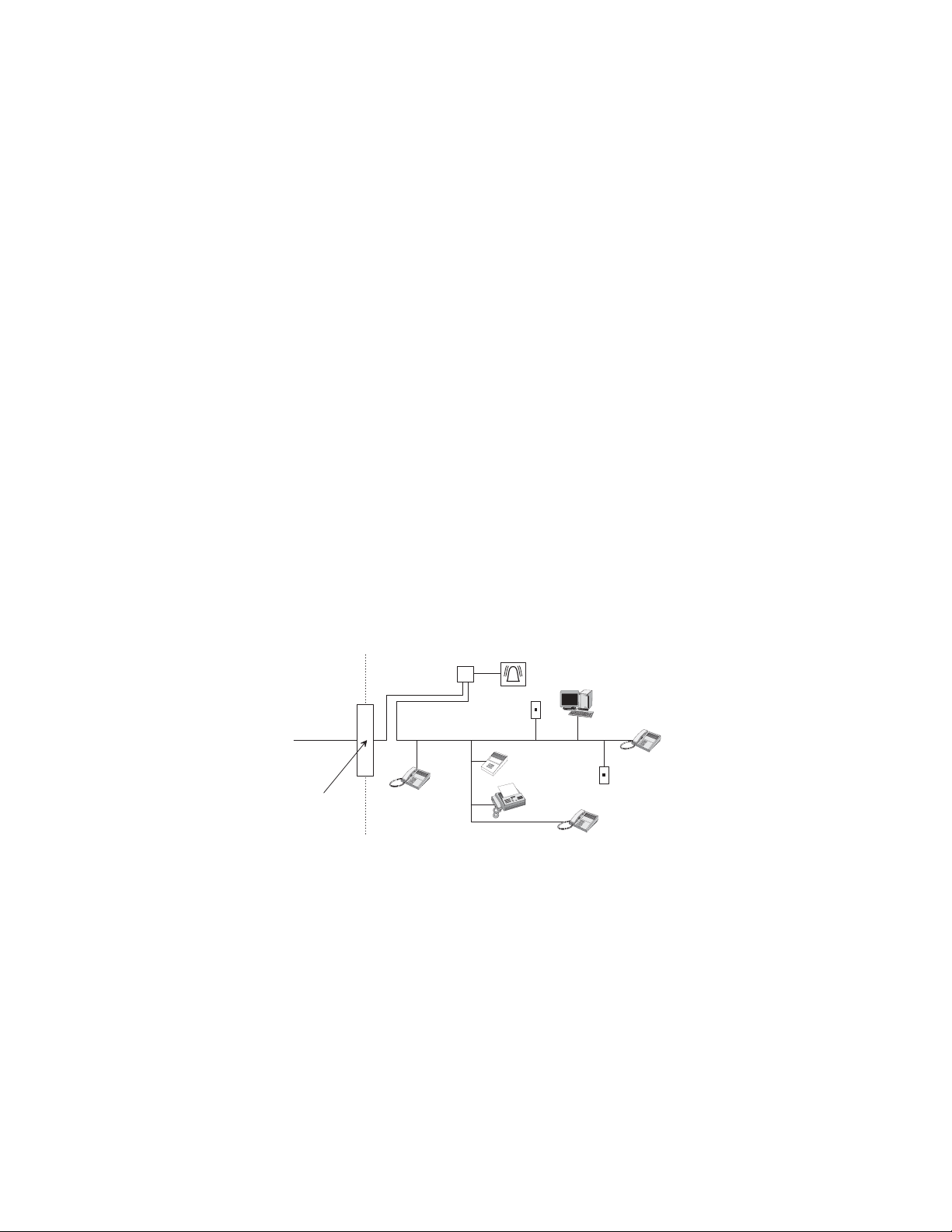
Alarm dialing equipment must be able to seize the telepho ne line and place a call in an emergenc y situation. It mu st b e able to do this even if other equipment
(telephone, ans w er in g system, computer modem, etc.) already has the te lephone line in use. To do so, alarm dialing equipment must be connected to a properly installe d RJ31X jack that is el ectr ically in seri es and ahea d of all ot her equipme nt attach ed to the same teleph one lin e. Proper installation is depicted in the
following diagram. If you have any questions concerning these instructions, consult your local telephone company or a qualified installer about installing an
RJ31X jack and alarm dialing equipment for you.
C u s t o m e r P r e m i s e s E q u i p m e n t a n d W i r i n g
N e t w o r k
S e r v i c e
P r o v i d e r ' s
F a c i l i t i e s
T e l e p h o n e
L i n e
N e t w o r k
D e m a r c a t i o n
P o i n t
T e l e p h o n e
R J 3 1 X
J a c k
If this equipment causes harm to the te lephone network, the telephone company may tempo rarily disconnect your service. If po ssi ble, you will be notified in
advance. When advance notice is not practical, you will be notified as soon as possible. You will also be advised of your right to file a complaint with the FCC.
The telephone company may make changes in its facilities, equipment, operations, or procedures that could affect the operation of the equipment. You will be
given advance notice in order to maintain uninterrupted service.
If you experience trouble w i th this equipment, please c ont act the company that insta ll ed the equipment for service a nd/or repair information . T he telephone
company may ask you to disconnect this equipment from the network until the problem has been corrected or you are sure that the equipment is not mal functioning.
This equipment may not be used on coin service provided by the te le phone company. Connection to party lines is subject to state tariffs
U n u s e d
R J - 1 1 J a c k
A n s w e r i n g
S y s t e m
A l a r m D i a l i n g
E q u i p m e n t
F a x M a c h i n e
T e l e p h o n e
C o m p u t e r
U n u s e d
R J - 1 1 J a c k
T e l e p h o n e

Canada Notice
The Canadian Department of Communic ations label identifies certified equipment. This certification means tha t the equipment meets certai n telecommunications network protective, operational, and safet y requirements. The de partment does not guarantee the equipment will operate to t he user’s satisfaction.
Before installing this equipment, users should ensure that it is permissible to be connected to the facilities of the local telecommunications company. The
equipment must also be installe d usi ng a n acceptable method of conn ec ti on. In some cases, the company’s inside wiring associate d wit h a single-line individual service may be extended by means of a certified co nne ctor assembly (teleph one extension cord). The cu sto me r should be aware that compliance with the
above conditions may not pr event degradation of servic e in som e si tuations.
Repairs to certified equipment should be made by an authorized Canadian maintenance facility designated by the supplier. Any repairs or alterations made by
the user to this equipment, or equipment malf unctions, may give the telecommunicati o ns co mp an y cause to request the user to disco nnect the equipmen t.
For your protection, make sure that the electrical grou nd c onnections of the power utility, telephone lines, and int ernal metallic water pipe system, if present,
are connected together
Do not attempt to make connections yourself. Contact the appro priate electrician or elec-
!
Caution
The Load Number (LN) assigned to each terminal device denotes the percentage of the total load to be connected to a telephone loop which is used by the
device, to prevent overloading. The termination on a loop may consist of any combination of devices subject only to the requirement that the total of the LNs
of all the devices does not exceed 100. Load Number: .1 The term “IC:” before the certification/registration number only signifies that the Industry Canada
technical specifications were met. IC: 867A 787SIMON
“AVIS: - L ´étiquette du ministère des Communications du Canada identifie le matériel homologué. Cett e ét iquette certifie que le matériel est conforme a certaines normes de protection, d ´ exploitation et de sécurité des rése aux de télécommunications. Le ministère n ´ assure toutefois pas que le matériel fonctionnera a la sati s f action de l ´ utilisateur.
Av an t d ´ installer ce matériel, l ´ utilisateur d oi t s ´ assurer qu´ il est permi s d e le raccorder aux inst all ations de l ´ enterprise locale de téléco mmu n ication. Le
matériel doi t également etre ins tallé en suivant u n e méthod acceptée d e raccordement . Dans certains cas , les fils intér ieurs de l´ enterprise utilisés pour un service individuel a ligne unique peuvent etre prolongés au m oye n d´ un dispositif homologué de racc ordement (cordon prolonga t eur tél éphonique interne). L ´
abonné ne doit pas oublier qu ´ il est possible que la conformité aux conditions énoncées ci-dessus n ´ empechent pas le dégradation du service dans certaines
situations. Actu el lement, les enterpr ises de télécommun ica tion ne permettent pas que l ´ on ra cco r d e leur matériel a d es jacks d ´ abonné, sauf dans les cas précis prévus pas les tarrifs particuliers de ces enterprises.
Les réparations de matérie l ho mologué doivent etre effectué es pa s un centre d ´ entretien canadien autorisé désigné par le fournisseur. La compagne de télécommunications peut dema nder a l ´ utilisateur de débranche r un appareil a la suite de réparations ou de modifi ca ti ons effectuées par l ´ utilisateur ou a cause
de mauvais fonctionnement.
Pour sa propre protection, l ´ utilisat e ur doit s ´ assurer que tous les fils de mise a la terre de la sou rce d ´ énergie électrique, des lignes téléphoniq ue s et des
canalisations d ´´ eau métalliques, s ´ il y en a, sont raccordés ensemble. Cette précaution est particulièrement importante dans les régions rurales.
Avertissment. - L ´ utilisateur ne doit pas tenter de faire ces raccordements lui-meme; il doit avoir recours a un service d ´ inspection des installations électriques, ou a electricien, selon le cas”.
Une note explicative sur les indices de charge (voir 1.6) et leur emploi, a l ´ intention des utilisateurs du matériel terminal, doit etre incluse dans l ´ information
qui accompagne le mate rie l ho mologué. La note pourrait etre rédigée selon le modèle suivant:
“L ´ indice de charge (IC) assigné a chaque dispositif terminal indique, pour éviter toute surcharge, le pourcentage de la charge totale qui peut etre rac c ordée a
un circuit téléphonique bouclé utilisé par ce disposit if. La te rminaison du circuit bouclé peu t et re constituée de n ´ import som m e de s ind ic es de charge de l ´
ensemble des dispositifs ne dépasse pas 100.”
L ´ Indice de charge de cet produi t est ____________.
tric inspections authority.

)
*(,QWHUORJL[
*(,QWHUORJL[6LPRQLVDWUDGHPDUNRI*(,QWHUORJL[$OORWKHUWUDGHPDUNVDUH
SURSHUWLHVRIWKHLURZQHUV)RUUHSULQWVRUGHUGRFXPHQW5HY'
$OOULJKWVUHVHUYHG
6HFRQG6WUHHW1RUWK
1RUWK6DLQW3DXO01

TABLE OF CONTENTS
Introduction. . . . . . . . . . . . . . . . . . . . . . . . . . . . . . . . . . . 1
Security System Beeps, Lights, and Messages . . . . . 3
How to Use Your Control Panel. . . . . . . . . . . . . . . . . . . 5
How to Use Your Touchpads . . . . . . . . . . . . . . . . . . . . . 8
Programming Your System . . . . . . . . . . . . . . . . . . . . . . 9
System Tests & Trouble Beeps . . . . . . . . . . . . . . . . . . .12
Your Emergency Evacuation Floor Plan . . . . . . . . . . . .14
Alarm System Limitations . . . . . . . . . . . . . . . . . . . . . . .15
Index. . . . . . . . . . . . . . . . . . . . . . . . . . . . . . . . . . . . . . . . .16
Quick Reference Table . . . . . . . . . . . . . . . . . . . . . . . . . .Back Cover
Important Messages to the Owner:
In the following parag raphs there may be some terminology th at you are not famil iar with. Reread thi s section after you fa miliarize
yourself with your security system.
Arming Your System with Doors or Windows Open:
after the exit dela y has ex pired. This m eans they wi ll not be prot ecting your h ome. If you wish to bypas s a s ensor a fter yo u ha ve
armed your system , you must first disarm the syste m, then open the door or wi ndow which yo u want byp assed. You r system wi ll
tell you if a protected door or window is open when you arm the system. If your system includes 24-hour protection sensors on
items such as gun or j ew el ry cas e s , y ou mu st do an additional di sa rm c al led subdisarm before accessing t hes e a r eas to av oi d
causing an alarm. The master acc ess code and pa nic code can subdisarm. Wh en the system is disarmed, us ing the Cont rol Panel, the Remote Handh eld Touchpad, or Toucht alk 2-Way RF Touchpa d, enter the master acce ss code or panic code t o subdisarm
the system. The Control Pan el is sub dis arm ed when the Disarm button is flashing. If the panic co de was use d, an al arm will be
reported to the central station.
CAUTION! If you use the Control Panel to arm your security system when leaving your home, you need to be aware of the following: You need to exit before the end of the delay peri od or an alarm wil l sound .
or 4 beeps at the beginnin g of the ex it delay (see the ta ble “Pane l Beeps ” on pag e 3 of this manual to determine the meaning of
control panel/system beeps). At the end of the exit delay, the system beeps 2, 3, or 4 additional beeps. If you exit at that time
(after the exit delay), your system assumes you are now returning to your home. The system is now counting down the entry
delay time and will expect you to disarm the system within the entry delay time or it will alarm.
Something may have happened while you were away! If you enter your home and controlled lights that are normally off are
on and/or you hear alarm sirens, an intruder may be inside or another emergency may have occurred. Leave immediately, and
call for non-medical emergency help.
Canceling Accidenta l Alarms : You have up to 120 sec onds (programmab le by the ins talle r) after caus ing an accid ental al arm to
disarm your securit y syste m. See y our in stalle r to det ermine this a mount of tim e. If th e progra mmed seco nds ha ve pass ed, yo u
must call the central monitoring station to cancel the alarm.
Any sensors which are open when the system is armed will be bypassed
Remember, when y ou arm y ou will hear 2, 3,
Notices for UL-Listed Installations:
• This system is suitable for Grade A household burglary applications.
• The Freeze Sensor, Glass Guard and Shock Sensors are not UL Listed.
• The garage door opening feature used with this system has not been evaluated by UL.
1
Introduction to Your System
Your security system uses wireless technology to warn your
family about intrusion and fire. It may also be used to control
lights and appliances within your home.
The system is designed to be monitored and/or to send messages to a numeric pager.
The security system uses devices called sensors which use
radio waves to communicate alarms to the Control Panel.
The system is supervised, meaning that the Control Panel
checks the status of each sensor to detect problems. If the
Control Panel detect s tr oub le i t w il l n oti fy y ou with beeps and
indicator lights on the Control Panel itself.
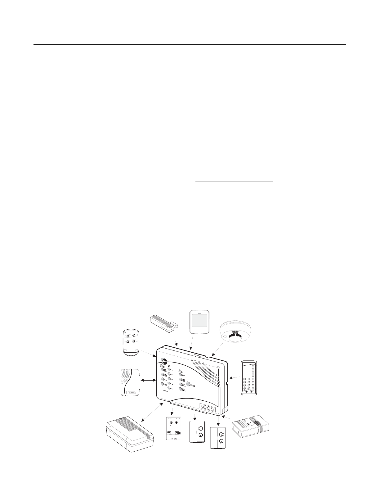
Typical Security System Components
A typical security system ins tal lation consists of the following
devices:
Control Panel
The Control Panel is us ed to ope rate an d program your security system. It commu ni cat es to yo u through panel voice me ssages, panel beeps, and by lighting buttons on the Control
Panel. The Control Panel can communicate to a central monitoring station and/or a nu meric pager. The Control Pan el may
come with 2-Way Voice On-Board.” This feature allows the
Central Station to commun icate with the user if there is a problem at the security system site.
Audio Verification Module (Not for use with Basic
Model)
The Audio V erific ation Module (AVM) gives the central st ation
operator the ability to hear what ’ s happ eni ng at the prem is es
during an alarm and speak directly to the system owner. The
operator can determ ine how serio us an alarm i s, find out w hat
kind of help is needed, and dispatch the appropriate assistance.
Remote Handheld Touchpad and Touchtalk 2Way RF Touchpad
These touchpads are used to control the security system primarily from within the home.
(Not for use with Basic Model)
KeyChain Touchpads
KeyChain Touchpads are used to contro l the se cur ity syste m
from within or near the outside of your home.
Indoor Motion Sensors
Indoor Motion Sensors dete ct moti on . They ma y be use d for
intrusion protection or to sound chimes on the Control Panel.
Outdoor Motion Sensors
Outdoor Motion Se nsors det ect motio n in a pro tected ou tdoor
area and can sound chim es or turn on outside lights. The y are
not used for intrusion detection.
Door/Window Sensors
Door/Window Sensors detect the opening of a door or window.
Smoke Sensors
Smoke Sensors detect smoke. They have a built in siren
which sounds when smoke is detected.
Modules (Not for use with Basic Model)
Modules are used to control lights, appliances, and a garage
door. Only unit numbers 1-8 may be used for individual light,
appliance, or garage door control.
MOTION
SENSOR
15
13
11
O
M
LAMP
MODULE
1
3
5
7
9
A
C
E
GK
I
1
3
15
5
13
11
7
9
A
C
O
E
M
GK
I
APPLIANCE
MODULE
SMOKE
SENSOR
SYSTEM
STATUS
ARM
Doors &
Windows
ARM
Motion
Sensors
DISARM
3
1
4
526
7
89
Off
On
EMERGENCY
sP
d&sre s Hol hBtoeKy
-
REMOTE
HANDHELD
TOUCHPAD
C A R B O N
M O N O X I D E
D E T E C T O R
CARBON MONOXIDE
ALARM
8988G21D.DSF
KEYCHAIN
TOUCHPAD
TOUCHTALK
2-WAY RF
TOUCHPAD
AUDIO VERIFICATION
MODULE
DOOR/WINDOW
SENSOR
CONTINUOUS
MOMENTARY
GARAGE DOOR
MODULE
ON
1
3
15
5
13
11
7
9
UNIT CODE
X-10 POWERHOUSE
OFF
A
C
O
E
M
GK
I
HOUSE CODE
SOUNDER ONLY
SOUNDER & RELAY
RELAY ONLY
2

Security System Beeps, Lights, and Messages
Your security syst em comm unica tes to yo u th rough the use of pa nel vo ice me ssag es, pan el beep s, indi cator li ght s on the panel
itself, and to a numeric pager if programmed.
You communicate to your security system with key presses on the Control Panel, touchpads, or through the use of a remote
telephone. Disarming and programming require you to input a 4-digit access code. The Master Access Code default is 1-2-3-
4 when the security system is shipped from the factory. You should change it to a code known only by you.
Panel Voice Messages
When you press the buttons on the Control Panel or the touchpads, the Control Panel responds with voice messages. Panel
voice can be enabled or disabled (see “What You Can Change:” on page 9).
These messages may res pon d wi th s ys te m i nfo rma tio n or prom pt yo u to tak e f urth er ac ti on. For example, if you want to dis arm
the system and you press the DISARM button, the Control Panel responds by saying, Please enter your access code.
If you press a button an d the feature has not been pr ogrammed into th e Control Pane l, the panel vo ice will respo nd with Function
not available. An example of this situation is pressing the Control Panel button CHIME Special Motion when you have no non-
intrusion Motion Sensors in your installation. The panel voice would respond with, Function not available.
Panel Beeps
Panel beeps are used to indicate keypresses, status, and problems with the system. Panel beeps can be enabled or disabled
(see “What You Can Change:” on page 9).
Use the following table to understand the beeps used by the security system.
Activity Beep Response
ARM Doors & Windows Exit delay beeps sound 2 times when you arm* and 2 times at the end of the delay time;
Entry delay beeps sou nd 2 times ev ery 5 seco nds and 2 tim es per seco nd during the last 10
seconds
ARM Motion Sensors Exit delay beeps sound 3 times when you arm* and 3 times at the end of the delay time;
Entry delay beeps sou nd 3 times ev ery 5 seco nds and 3 tim es per seco nd during the last 10
seconds
ARM Doors/Windows &
Motion Sensors
DISARM 1 beep
CHIME DOORS 2 beeps (feature must be programmed by installer)
CHIME SPECIAL MOTION
(Not Included in Basic
Model)
Trouble Beeps 6 beeps every minute. Press SYSTEM STATUS button twice to stop beeps for 4 hours
No Activity Beeps 20 beeps every minute for 5 minutes (feature must be programmed by the installer)
* You will not get initial exit delay beeps if you are arming from a Touchtalk 2-Way RF Touchpad.
Note: You may receive a different number of panel beeps if buttons are pressed quickly.
Exit delay beeps sound 4 times when you arm* and 4 times at the end of the delay time;
Entry delay beeps sou nd 4 times ev ery 5 seco nds and 4 tim es per seco nd during the last 10
seconds
3 beeps (feature must be programmed by installer)
3
Alarm Sirens and Lights
Exterior and interior sirens make 3 different alarm sounds on the premises, each indicating a different type of alarm. Sirens will
time-out and stop sounding after the siren timeout (programmable by the installer). System controlled lights also indicate the type
of alarm.
Use the following table to understand alarm sounds and controlled lights.
Alarm Type Interior Siren Sound Exterior Siren Sound System Controlled Lights
(Not Included in Basic Model)
Fire (Temporal 3) 3 siren pulses then off
for 2 seconds, 3 siren
pulses then off for 2
seconds, . . .
Intrusion On steady On steady Flashing
Emergency Fast on-off _________________ On steady
3 siren pulses then off
for 2 seconds, 3 siren
pulses then off for 2
seconds, . . .
On steady
Panel Indicator Lights
Use the following table to understand the panel indicator lights.
Button When the Button Light is On When the Button Flashes
ARM Doors & Windows Doors/Windows armed Doors/Windows armed &
No Entry Delay on
ARM Motion Sensors Motion Sensors armed Motion Sensors armed &
Latchkey on
DISARM System disarmed System subdisarmed
SYSTEM STATUS System trouble or Open Sensor System in alarm
CHIME Doors Door will cause chime _____________________
CHIME Special Motion
(Not Included in Basic Model)
Motion will cause chime _____________________
LIGHTS Time Activated
(Not Included in Basic Model)
LIGHTS Sensor Activated
(Not Included in Basic Model)
Light schedule is on _____________________
Sensors will cause light to go on _____________________
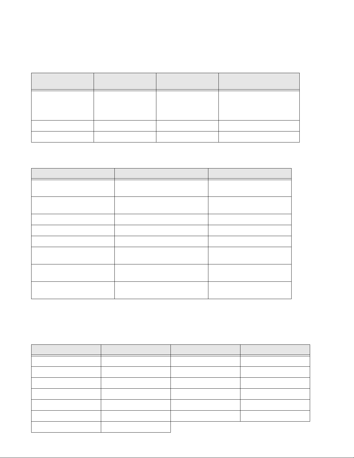
Numeric Pager
You may program your security system to send a numeric message indicating system activities to your pager. The system will
send the message twice. See “Programming Your System” on page 9.
Use the following table to determine what the numeric message is reporting.
Reports Numeric Message Reports Numeric Message
Phone Test -101 -101 Intrusion -108 -108
AC Power Restoral -102 -102 Fire -109 -109
AC Power Failure -103 -103 Disarming -110 -110
Latchkey -104 -104 Arming -111 -111
No Activity -105 -105 Fail to Disarm -112 -112
Panic Code -106 -106 Fail to Arm -113 -113
Emergency -107 -107
4
 Loading...