

ITI Concord Express Owner's Manual

&RQFRUG([SUHVV
ITI Part No. 60-806
A r m e d
R e a d y
Document Number: 466-1667 Rev. D
February 2003
Contents
Getting to Know Your Security System........................... 1
Overview................................................................... 1
Communicating with the Panel........................................ 1
Instructing the Panel ................................................. 2
How Your System Communicates with You............. 2
Fire and Smoke Alarms.................................................... 2
Clearing Smoke Sensors .................................................. 3
What Happens When There is an Alarm.................. 3
Arming Your System........................................................ 3
Level 1—OFF........................................................... 3
Arming Level 2—STAY........................................... 3
Arming Level 3—AWAY.......................................... 3
Keychain Touchpad Arming............................................ 4
Quick Arm........................................................................ 4
Quick Exit........................................................................ 4
Using the Chime Feature.................................................. 4
Preventing Accidental Alarms......................................... 4
Aborting Accidental Alarms..................................... 5
Guidelines for Preventing Accidental Alarms.......... 5
Exit and Entry Delay Times............................................. 5
Extended Delay ......................................................... 6
Exit Extension............... ...... ...... ................................ 6
No Delay—For Instant Alarm .................................. 6
Auto STAY Arming Feature ..................................... 6
Arming While a Door or Window is Open...................... 6
Bypassing a Sensor Directly..................................... 7
Bypassing a Sensor Indirectly................................... 7
Was the Bypass Successful?..................................... 7
Checking the Status of Your System................................ 7
Short System Status.......................................................... 8
Full System Status..................................................... 8
System Alarm Sounds............................................... 8
Panic Alarms.................................................................... 8
Fire Panic.................................................................. 8
Police Panic Alarm ................................................... 8
Auxiliary Panic Alarm.............................................. 8
Siren Time-out.......................................................... 9
Access Codes ................................................................... 9
System Master Code................................................. 9
Regular User Codes.................................................. 9
Using the Programming Menus................................ 9
T e s t S y s t e m W e e k l y
A
B
C
D
p r e s s b o t h
p r e s s b o t h
p r e s s b o t h
O f f
N o D e la y
415
F e a tu r e s
7
S ta t u s
*
S ta y
2 3
S il e n t
S y s t e m
8
L i g h t s
0 #
A w a y
P a g e r
6
M e n u
9
B y p a s s
1ÃiÀ½ÃÊ>Õ>
Programming Access Codes..................................... 9
Setting the Time and Date.............................................. 10
Adjusting System Sounds and Touchpad Brightness..... 10
Arming Your System Silently ................................. 10
Adjusting the Touchpad Beeps ............................... 11
Adjusting the Touchpad Display Brightness........... 11
Notification by Pager ..................................................... 11
Pager Messages.................................... ...... ...... ....... 11
Streamlining the Page............................................. 12
Opening and Closing Reports........................................ 12
Latchkey Paging ............................................................. 12
No Activity Feature........................................................ 13
Using the Panel Download Feature................................ 13
System Information........................................................ 13
Testing the System ......................................................... 14
Automatic Test Features.......................................... 14
Manual Tests........................................................... 14
Troubleshooting.............................................................. 16
Trouble Beeps and Trouble Messages .................... 16
Appendix A: User Sheets............................................... 18
Account Number..................................................... 18
System Sensors ....................................................... 18
User Codes.............................................................. 18
Touchpad Information............................................. 19
Accidental Smoke and Fire Alarms........................ 19
Dialer Abort ............................................................ 19
Arming Information................................................ 20
Paging...................................................................... 20
If the Power Goes Out............................................. 20
No Activity Time.................................................... 20
System Information................................................. 20
Appendix B: Planning for Emergencies......................... 21
Floor Plan Example................................................. 21
Your Floor Plan....................................................... 21
Appendix C: Programming Your System....................... 23
Two Methods to Program Your System.................. 23
Programming Menus............................................... 24
Index............................................................................... 27
Notes .............................................................................. 28
FCC Notices
FCC Part 15 Information to the User
Changes or modifications not expressly approved by Interlogix Inc. can void t he user’s authority to operate the equipment.
FCC Part 15 Class B
This equipment has been tested and found to comply with the limits for a Class B digital device, pursuant to part 15 of the FCC Rules. These limits are designed
to provide reasonable prote ct io n against interference in a residential installat ion.
This equipment generates, uses, and can radiate radio frequ ency energy and, if not installed and used in accor dance with the instructions, may cause harmful
interference to radio communications. However, there is no guarantee that interference will not occur in a particular installation.
If this equipment does cause harmful interference to radio or television reception, which can be determined by turning the equipment off and on, the user is
encouraged to try to correct the interference by one or more of the fol lowing measures:
• Reorient or relocate the receiving antenna.
• Increase the separation between the equipment an d receiver.
• Connect the af f ected equipment and the panel receiver t o separate outlets, on different bra nc h circuits.
• Consult the dealer or an ex perienced radio/TV technician for hel p.
ACTA Part 68
This equipment comp lies with Part 68 of the FCC Rules. Located on this equipment is a label that contains, among other information, the FCC registration number and the ringer equivale nc e number (REN) for this equipmen t. If requ ested, this information must be provide d to t he tel ep hone company.
FCC Part 68 Registration No. B4ZUSA- 27621-AL-E REN: 0.2B
The REN is used to determine the maximum number of devices that may be connected to your telephone line. Excessive RENs on a telephone line may result in
devices not ringing in response to an inc o m in g ca ll . In mo st are as, the sum of all device RENs should not exceed five (5.0). To be certain of the number of
devices that may be connected to a line, as determined by the total RENs, contact the local telephone company. For products approved after July 23, 2001, the
REN for this product is part of the product identifier that has the format US:AAAEQ##TXXXX. The digits represented by ## are the REN without a decimal
point (e.g., 03 is a REN of 0.3). For earlier products, the REN is separately shown on the label.
A plug and jack used to connect thi s equi pment to the premises wiring and telephone net w ork must comply with the applicable FCC Part 68 rul es and requirements as adopted by ACTA. A compliant telephone cor d and modular plug is provided with this produc t . It is desi gne d to be connected to a compliant modular
jack that is also compliant. See th e Installation In s tr uctions for details.
Alarm dialing equipme nt must be a ble to se iz e the telephone line and place a call in an emergency situation. It must be able to do this e ven if other equipment
(telephone, answering system, c om puter modem, etc.) already has the tel ep hone line in use. To do so, alarm dialing equipment must be connected to a properly
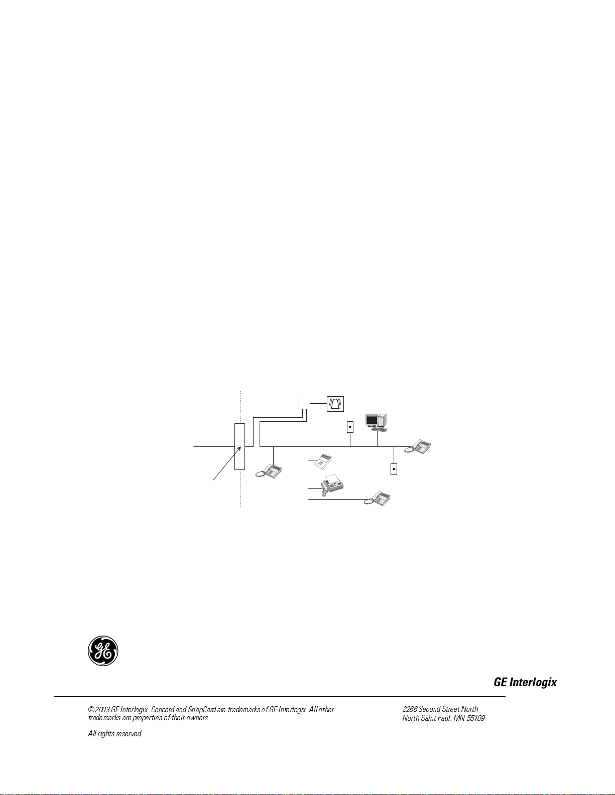
installed RJ31X jack that is electrically in series and ahead of all othe r equipment attached to the same telephone lin e. P roper installation is depicted in the following diagram. If you have any questions concerning these instructions, consult your local telephone company or a qualified installer about installing an RJ31X
jack and alarm dialing equipment for you.
C u s t o m e r P r e m i s e s E q u i p m e n t a n d W i r i n g
N e t w o r k
S e r v i c e
P r o v i d e r ' s
F a c i l i t i e s
T e l e p h o n e
L i n e
N e t w o r k
D e m a r c a t i o n
P o i n t
T e l e p h o n e
R J 3 1 X
J a c k
If this equipment causes harm to the telephone network, the telephone company ma y temporarily disconnect your service. If possible, you will be notified in
advance. When advance notice is not practical, you will be notified as soon a s possible. You w il l also be advised of your right to file a complaint with the FCC.
The telephone comp any may make changes in its facilities , e qui pm ent, operations, or procedures that could affect the operation of the equi pm ent. You will be
given advance notice in order to maintain uninterrupted service.
If you experience trouble with this equipment, please contact the company that installed the equipment for service and/or repair information. The telephone company may ask you to disconne ct this equipment from the network until the problem has been corrected or you are sure that th e equipment is not malfunction ing.
This equipment may no t be us ed on coin service provided by the telephone company. Connection to party lines is subject to state tariffs.
U n u s e d
R J - 1 1 J a c k
A n s w e r i n g
S y s t e m
A l a r m D i a l i n g
E q u i p m e n t
F a x M a c h i n e
T e l e p h o n e
C o m p u t e r
U n u s e d
R J - 1 1 J a c k
T e l e p h o n e
)
*(,QWHUORJL[&RQFRUGDQG6QDS&DUGDUHWUDGHPDUNVRI*(,QWHUORJL[$OORWKHU
WUDGHPDUNVDUHSURSHUWLHVRIWKHLURZQHUV
$OOULJKWVUHVHUYHG
*(,QWHUORJL[
6HFRQG6WUHHW1RUWK
1RUWK6DLQW3DXO01

Canada Notice
The Canadian Departm e nt o f Com m u nications label identifies certified e qui pm ent. This certification means tha t th e e qui pment meets certain telecommu nications network protective, operational, and safety requiremen ts. The department does not guarantee the equipment will operate to the user’s satisfaction .
Before installing this equipme nt, use rs shoul d ensure that it is permissible to be connected to the fa ci lities of the local telecommunications c ompany. The equipment must also be installed using an acce pt abl e method of connection. In some cases, the company’s inside wiring associated wit h a single-line indi v idual service may be extended by me ans of a certified connector assembl y (te lephone extension cord). The cu stomer should be aware that compl ia nc e w it h t he above
conditions may not prevent degradation of service in some situations.
Repairs to certified equipment should be made by an authorized Canadian maintenance facility designated by the supplier. Any repairs or alterations made by the
user to this equipment, or equipm e nt malfunctions, may give the telecommunications company cause to request the user to disconnect the equipment.
For your protection, make sure that the electrical ground connections of the power utility, telephone lines, and internal metallic water pipe system, if present, are
connected together
Do not attempt to make connections yourself. C ontact the appropri a t e e l e ct r i c i a n or elec-
!
Caution
The Load Number (LN) assigned to each terminal device denotes the percentage of the total load to be connected to a telephone loop which is used by the device,
to prevent overloading. The termination on a loop may consist of any combination of devices subject only to th e re quirement that the total of the LNs of all the
devices does not exceed 100. Load Number: .1 The term “IC:” before the certification/registration number only s ig nifies that the Ind ustry Canada techn ical
specificat ions were met. IC: 867A 787SIMON
“AVIS: - L ´étiquette du ministère des Communications du Canada identif ie le matériel homo logué. Cette étiqu ette certifie que le matériel est confo rme a certaines normes de protection, d ´ exploitation e t de sécuri té des ré sea ux de télécommunications. Le ministère n ´ assure toutefois pas que le matériel fonctionnera
a la satisfaction de l ´ utilisateur.
Avant d ´ installer ce ma tériel, l ´ utilisate u r d oit s ´ assurer qu´ il est permis de le raccorder aux installations de l ´ enterp r ise locale de télé communication. Le
matériel do it é gale ment et re inst all é e n s uiva nt u ne mét ho d ac ce ptée de racc or deme n t. Da ns cert ai ns c as, les fils i nté ri eur s de l´ e nterp rise util isés po ur un ser vic e
individuel a ligne unique pe uve nt etre prolongés au moyen d´ un dispositif homo lo gué de raccordement (cordon prolongateur téléphonique interne). L ´ abonné
ne doit pas oublier qu ´ il est possible que la conformité aux conditions énoncées ci-dessus n ´ empechent pas le dégradation du service dans certaines situations.
Actuellement, les enterprises de télécommunication ne permettent pas que l ´ on raccorde leur matériel a des jacks d ´ abonné, sauf dans les cas précis prévus pas
les tarrifs pa r ticuliers de ces enterprises.
Les réparations de matériel homologué doivent etre effectuées pas un ce nt re d ´ entretien canadien autorisé désign é par le fournisseur. La compagne de télécommunications peut demander a l ´ utilisateur de débrancher un appareil a la suite de réparations ou de modifications effectuées par l ´ utilisate ur o u a ca use de mau vais fonctionnement.
Pour sa propre protection, l ´ utilis at eur doit s ´ assurer que tous les fils de mise a la terre de la source d ´ énergie électrique, des lignes téléphoniques et des
canalisations d ´´ eau métalliques, s ´ il y en a, sont racco rdé s ensemble. Cette précaution est particulièrement importa nt e dans les régions rurales.
Avertissment. - L ´ utilisateur ne doit pas tenter de faire ces raccordements lui-meme; il doit avoir recours a un service d ´ inspection des i ns tallations électr iq u es,
ou a electricien, selon le cas”.
Une note explicative sur les indices de cha rge (voi r 1. 6) et le ur em ploi, a l ´ intention des utilisateurs du matériel termina l, doit etre incluse dans l ´ information
qui accompagne le materiel hom o logué. La note pourrait etre rédigée selon le modèle suiva nt :
“L ´ indice de charge (IC) assigné a chaque dispositif terminal indique, pour éviter toute surcharge, le pourcentage de la charge totale qui peut etre raccordée a un
circuit téléphonique bouclé utilisé par ce dispositif. La terminaison du circuit bouclé peut etre constituée de n ´ import somme des indices de char ge de l ´ ensemble des dispositifs ne dépasse pas 100.”
L ´ Indice de charge de cet produit est ____________.
tric inspections authority.

Commands at a Glance
To do this: Press:
Disarm the system.
Cancel an accidental alarm.
Arm to Level 2—STAY. 2 + Code
Arm to Level 3—AWAY. 3 + Code
Send a police alarm. Press and hold both POLICE
Send an auxiliary alarm. Press and hold both AUXILIARY
Send a fire alarm. Press and hold both FIRE
Arm system with No Delay.
1 + Code
buttons for 2 seconds.
buttons for 2 seconds.
buttons for 2 seconds.
2 + Code + 4 or
3 + Code + 4
Arm system to send a
Latchkey page.
Bypass a sensor. Indirectly: 2 + Code + ƒ or
2 + Code + 6 or
3 + Code + 6
3 + Code + ƒ
Directly: ƒ + Code + Sensor Number
Arm system silently.
5 + 2 + Code or
5 + 3 + Code
Check the system status.
Turn Chime on/off. 7 + 1
Check alarm memory. 7 + 6
Initiate a phone test. 8 + Code + 2
Initiate a sensor test. 8 + Code + 3
Turn lights on/off 0 + 0
‚
Getting to Know Your Security System
1
2
3
6
9
8
5
4
7
S T
0
B Y
O FF
S TA Y
A W AY
N O D EL A Y
C HI M E
S TA T US
B YP A SS
C OM M A N D
Getting to Know Your Security
System
This manual describes how to operate your system. It
describes basic arming and disarming commands as well
as how to program system features.
The dealer or installer may have already discussed the
details of your system with you. Record your system
details in the User Sheets located in Appendix A.
Overview
Your security system is made up of different parts. Each
plays a special role in the system’s operation:
The panel is at the heart of your system. It stores the intelligence to monitor
all the sensors and devices in the system. The panel is the piece of equipment that activates sirens and initiates a
call to the central station in an alarm
situation.
Touchpads are used to arm, disarm, and program your
system.
Your system may also use wireless,
handheld touchpads that can be carried from room to room.
Keychain touchpads are also wireless and
are handy for simple arming and disarming functions. Keychain touchpads can be
carried off-site.
The installer can program the keychain
touchpad to send a Police or Auxiliary panic alarm.
Wireless panic button touchpads are
dedicated to sending one signal only—
usually a Police or Auxiliary panic
alarm. Panic button touchpads are usually kept near the user.
Door and window sensors protect the
perimeter of your home by alerting the
panel when a door or window is opened.
Motion detectors in hallways or rooms detect a
person moving across the field of detection.
Your system may use a wall-mounted touchpad that looks
like one of these:
S y s te m is O K
A r m e d
Q u ic k G u id e
D is a rm S y st e m / C an c e l A la r m
P re ss 1 + C O D E .
A rm t o S T A Y
1
C lo se a ll pr ot ec te d do o rs a nd w i nd o w s.
2
P re ss 2 + C O D E .
3
P re ss 4 to a rm de la y do o rs in st an tl y,
if d es ire d .
A rm t o A W A Y
1
C lo se a ll pr ot ec te d do o rs a nd w i nd o w s.
2
P re ss 3 + C O D E .
3
E xi t p r em is es t hr ou g h de la y do o r.
Z o n e/ S e ns o r N u m b e r
0 1
0 2
0 3
0 4
0 5
0 6
0 7
B yp a s s S en s o rs
1
A rm sy ste m t o de s ire d le ve l.
2
P re ss B Y PA S S + C O D E + S e ns o r N o .
T u rn C H IM E O n / O f f
1
M a k e s u r e s y ste m i s d is a rm e d.
2
P re ss 7 + 1 to t u rn C H IM E on o r o ff.
P ro g ra m U s e r S et ti n gs
1
M a k e s u r e s y ste m i s d is a rm e d.
2
P re ss A o r B to s cr ol l t hr o ug h m en u s.
P re ss # t o se lec t op ti o n or a cc ep t en tr y.
P re ss to d es el ec t op ti on o r ca n ce l e n try .
P re ss 1 fo r O F F; p re ss 2 fo r O N ;
p re s s 0 - 9 fo r o th e r en tr ies .
0 8
0 9
1 0
1 1
1 2
1 3
1 4
T e st S y s te m W e e kl y
A41
p re s s bo t h
B
p re s s bo t h
C
p re s s bo t h
D
R e a d y
A w a y
S t a y
O f f
2 3
P a g e r
N o D e l a y
S il e n t
5
6
F e a t u re s
S y s te m
M e n u
8
9
7
S t a tu s
L ig h t s
B y p a s s
0 #
*
T e st S y s te m W e ek l y
A41
p re s s b o th
B
p re s s b o th
C
p re s s b o th
D
A w a y
S t a y
O f f
2 3
P a g e r
N o D e la y
S i le n t
5
F e a t u r e s
6
S y s t e m
M e n u
8
7
9
S t a t u s
L ig h ts
B y p a s s
0 #
*
The first touchpad is called a fixed display touchpad. It
communicates by using indicator lights, lighted text, and
an 11-character display. The second touchpad is called an
alphanumeric touchpad and communicates by displaying
text on a two-line display.
Environmental sensors such as gas,
smoke, and heat detectors remain alert for
the presence of fire or carbon monoxide 24
hours a day.
Communicating with the Panel
Your system can be set up to communicate with you
through:
Status beeps
Alarm sirens
Touchpad text
Pager information
A s e n s o r i s a c t i v a t e d .
T h e s e n s o r a l e r t s t h e
p a n e l i m m e d i a t e l y .
T h e p a n e l a c t i v a t e s s i r e n s . I f t h e
s y s t e m i s m o n i t o r e d , t h e p a n e l
c a l l s t h e c e n t r a l m o n i t o r i n g s t a t i o n .
T h i s d e c i s i o n i s b a s e d o n s y s t e m
T h e c e n t r a l m o n i t o r i n g s t a t i o n
o p e r a t o r r e p o r t s t h e a l a r m t o
t h e p o l i c e o r f i r e d e p a r t m e n t .
p r o g r a m m i n g a n d t h e c u r r e n t
a r m i n g l e v e l .
1

Fire and Smok e Alarms
C o m m a n d A c c e s s C o d e
Instructing the Panel
Not just anyone can walk up to a touchpad and operate
your security system. Before the system will process most
commands, users are required to enter a pre-programmed
4-digit access code. See “Access Codes” for detailed
information.
Keychain touchpads that are enrolled as part of the system
do not require an access code, but are usually kept in an
individual’s pocket or purse.
If you would rather use an actual key to arm and disarm
the system, your security dealer can install a special key
and keyswitch in your home.
How Your System Communicates with
You
Touchpads and interior sirens produce a variety of operating beeps to inform you of different system states and
operations. The fixed display to uchp ad also uses indicator
lights.
Key Beeps
Pager Notification
Your system can dial the phone numbers of three different
pagers to notify users of events they may want to b e aware
of. Some of the events include:
when the system is disarmed,
when the system is armed,
trouble conditions in the system, and
alarm conditions.
For more information, see “Notification by Pager.”
Indicator Lights
The fixed display touchpad used with Concord™ Express
Systems includes ARMED and READY indicator LEDs
(light emitting diodes) that provide instant feedback.
ARMED
The red LED is the ARMED indicator. It will flash during
the exit delay when you are arming the system to level 2
(STAY) or level 3 (AWAY). It will also flash during the
entry delay, before you disarm your system.
The arming indicator will stop flashing
on—when the exit delay expires and the system is armed.
—but will remain
A Key beep is the tone you hear when you press a button
on a touchpad. The sound confirms that the button was
pressed adequately. Key beeps can be turned on or off by
the installer.
Status Beeps
Status beeps from touch pads or s irens sou nd when there is
a change in the current status of the system. Status beeps
are not alarms, but they do warrant your attention.
There is more than one type of Status beep:
Exit Delay beeps indicate that an arming command
has been entered and the countdown to arming has
begun.
Entry Delay beeps indicate that you’ve entered the
building and the countdown to an alarm has begun.
(So disarm the system as soon as you get in!)
Trouble beeps tell you that there is a prob lem with the
system or one of its components.
Chime feature beeps tell you that a door was opened.
Protest beeps inform yo u that yo u’re trying to arm th e
system while there is an open door or window.
Sensor test beeps are the sound the system makes dur-
ing a sensor test to indicate that a sensor was tested
properly.
Status beeps are described in more detail throughout the
manual.
The arming indicator will be off when the system is disarmed.
READY
The green LED is the READY indicator. It will be on
whenever the system is functioning normally. The ready
indicator shuts off if the system detects a trouble condition.
Ìi
Any time you n otice that the re ady l ight is not o n, yo u
should press the STATUS button to find out what the
trouble condition is.
Fire and Smoke Alarms
If your system contains smoke and fi re sensors, it mon itors
the premises for smoke and f ire alarm s 24 hours a day and
in all arming levels.
These alarms cannot be cancelled or aborted and are
always reported to the central s tation. Since many communities charge for dispatching the fire department in error,
your dealer may give you s pecific inst ructio ns to fo llow i n
the event of an accidental smoke or fire alarm. Record
these instructions in the Appendix A User Sheets under
“Accidental Smoke and Fire Alarms.”
2

Arming Your System
Clearing Smoke Sensors
Once a smoke sensor has been in alarm, it
is considered “Open” or in “Trouble”
until it is reset:
Press
1 + Code once to silence the alarm, then press
+ Code again to reset the smoke sensor.
1
What Happens When There is an Alarm
In the event of an alarm, several things happen at once:
Sirens and hardwired touchpads emit emergency
tones
Panel notifies the central station for help.*
Message appears on fixed display or alphanumeric
touchpads.
* Your system may or may not be monitore d. If it is no t
monitored, no call will be made.
Arming Your System
Since your security needs may vary throughout the day,
the system was designed with three arming levels. By arming your system to a particular level, only those sensors
programmed to detect in that arming level will report
alarms.
To disarm to Level 1—OFF using a touchpad:
1. Press
2. Enter your access code. Touchpads display date and
3. The system sounds one long beep.
1. Touchpads display “Enter Code.”
time or programmed text.
Arming Level 2—STAY
There are times when you want intrusion protection, but
still want the freedom to move around within your house
without setting off an alarm. For example, in the evening
when your family is inside for the night. In this and similar
situations, arm your system to 2—STAY.
To arm to Level 2—STAY using a touchpad:
1. Close all protected perimeter doors and windows.
2. Press
3. Enter your access code. Touchpads display, “Armed
4. The system sounds two short beeps. ARMED indica-
5. If leaving the premises, exit through a designated
2 at any touchpad. Touchpads display, “Enter
Code.”
to STAY.”
tors on fixed display touchpads will light (indicato r
will flash during the exit delay). The exit beeps begin.
delay door immediately.
Arming Level 3—AWAY
Level 1—OFF
Use Level 1 when intrusion detection is n ot neces sary. For
example, on an active Saturday morning—kids playing
inside and out; someone working in the garage; various
house projects going on.
Even though Level 1 disarms the sys tem, your sy stem con tinues to monitor fo r fire, s moke, carbon m onoxide, and/ or
panic alarms if your system has these devices installed.
Here are some other situations in which you’d set the system to Level 1—OFF:
Upon entering your armed home or business. When
entering the armed premises through a designated
delay door, the entry delay time begins. Entry Delay
beeps remind you to disarm the system.
Before opening a door or window while inside or out-
side the armed home or business. When you wake up
in the morning and want to get your newspaper, you
must disarm the system before opening the door to
prevent an accidental alarm. (See the section on “Preventing Accidental Alarms” if you would like to be
able to leave quickly when the system is armed.)
To stop sirens and cancel an alarm. When an alarm
condition occurs, disarming the system turns off any
sirens.
At other times, you want every sensor to be alert: When
the family is away from home, or, in a business, after closing time.
In this and similar situations, set your system to 3—A WAY
for maximu m protection. All sensors are active—perimeter door and window sensors, and interior motion detectors.
To arm to Level 3—AWAY using a touchpad:
1. Close all perimeter doors and windows.
2. Press
3. Enter your access code. Touchpads display, “Armed
4. The s ystem sounds three s hort beeps. ARMED indica-
5. Exit through a designated delay door immediately.
3 at any touchpad. Touchpads display, “Enter
Code.”
to AWAY.”
tors on fixed display touchpads will light (indicato r
will flash during the exit delay). The exit beeps begin.
3

Keychain Touchpad Arming
Ìi
«ÀÌ>ÌÊt
Ìi
Keychain Touchpad Arming
To disarm your system with a keychain touchpad, press the Unlock button.
Your installer can set up your keychain touchpad to arm the system in one of two ways:
1. Press the Lock button to arm the system directly to
Level 3 with no Exit delay. Using this method, you
would not be able to arm to Level 2.
2. Press the Lock button to increase the arming level
each time it is pressed (Level 1 to Level 2, or Level 2
to Level 3). The Exit delay time would be applied.
T o u s e Q u i c k E x i t
D
I n L e v e l 2 H O M E , s i m p l y p r e s s
b e f o r e o p e n i n g t h e d o o r .
T h e d o o r m u s t b e c l o s e d a g a i n
w i t h i n 2 m i n u t e s t o a v o i d a l a r m .
C o n t a c t y o u r d e a l e r i f y o u ' d
l i k e t o u s e t h i s f e a t u r e .
D
Quick Arm
Your system may be set up so that you’re able to arm the
system without using an access code.
To use Quick Arm:
Increase the arming level by simply pressing
2 or 3
at any touchpad.
Decreasing the arming level requires that the user enter a
code.
Quick Exit
In UL Listed systems, this feature is disabled.
Your system may be set up so that when your system is
armed to Level 2—STAY, you’re able to press
touchpad and simply walk out of the door without having
to disarm and rearm the system.
This is useful when your syst em is armed and yo u wa nt to
quickly pop outside to pick up the newspaper without disarming your system.
D on any
Using the Chime Feature
Turning on the Chim e feature is like havi ng bells on ever y
protected door and window . W hen this feature is on, sirens
and speakers sound 2 beeps when ever anyo ne o pens a p rotected door or window.
The Chime feature works only in Level 1—OFF.
To turn Chime on/off:
While in Level 1—OFF, from any touchpad, press
7 + 1. While the Chime feature is on, touchpads
display, “CHIME IS ON” or “Chime.”
When the system is armed again, Chime becomes deactivated.
Chime-On-Close
The Chime-On-Close feature works like the regular Chime
feature, but in addition to the double beeps heard upon
opening a protected door or window, the system sounds
one long beep when the door or window is closed again.
You can turn the Chime-On-Close feature on or off from
the programming menu. Refer to Appendix C, “Programming Menus” for information on programming your system.
If you step outs ide a nd are planni ng to c ome b ack in,
do not close the door behind you!
To use Quick Exit:
1. When the system is armed to 2—STAY, press D at
any touchpad. You will begin to hear one beep every
five seconds. These beeps will continue throughout
the 2 minute Quick Exit interval.
Opening the door without pressing D will cause the
entry delay to begin.
2. Open the door and go outside. Leave the door open if
you are planning to come back in!
3. Come back in within two minutes and close the door.
The system will rearm to 2—STAY.
4
Preventing Accidental Alarms
Your security system is engineered with advanced technology that reduces the chance of an accidental alarm caused
by a technical problem. In wireless systems, this technology prevents other devices, such as garage door openers,
ham radios, television remote controls, and cellular
phones, from interfering with your security system.
Most accidental alarms occur when leaving the hous e after
arming the system, or upon returning, before disarming the
system.
If, for example, you arm the system, then run upstairs for
something you forgot, the Exit Delay time may expire.
Once the Exit Delay expires, opening an armed door or
moving in front of a motion detector will cause an alarm.

Exit and Entry Delay Times
A
y
3
s
y
Aborting Accidental Alarms
Your system can be set up with the opportunity to abort an
accidental intrusion, Police or Auxiliary alarm.
If the Dialer Abort feature is turned on, disarming the system within a specified time period will silence the siren
and prevent the alarm from being reported to the central
monitoring station (thus aborting the alarm). See “Alarm
Information” in Appendix A to determine if this feature is
enabled for your system.
Fire alarms caused by smoke sensors, fire panic alarms,
and heat sensors cannot be ab orted. Dis arming a fire alarm
will silence the siren, but fire alarms are always reported.
If an accidental fire alarm has sounded, follow the procedures of your central monitoring station to prevent a false
dispatch.
To cancel an alarm:
Press
1 + Code.
Guidelines for Preventing Accidental
Alarms
Following these guidelines will go a long way toward preventing accidental alarms.
Close doors and windows before you leave your
house.
When getting ready to leave the house, gather the
things you want to take with you so you can exit
immediately after arming the system.
Always enter and exit within the programmed delay
times.
Make sure you leave through a door that has a delay
time set for it. If you arm your system, then leave
through a door without a delay time, an alarm will
immediately sound.
When you return, immediately disarm your system.
Be aware of the devices in your security system and
learn how each one operates.
Listen to system beeps. Take note of any touchpad
messages or lights that indicate the current system status.
If you have pets, ask your installer if you need pet
lenses in your motion detectors. Pets climb higher
than you may guess, causing alarms when you are
away.
Check the location of your smoke detectors. Smoke
detectors near bathrooms can be tripped by steam
from a shower. Smoke detectors near the kitchen can
be tripped by cooking smoke.
Refer to the User Sheet in Appendix A to determine what
the specific settings are for your system.
Exit and Entry Delay Times
After arming your system, you need time to
exit the building so you won’t set off an
alarm. Likewise, upon returning to your hom e
or business, you’ll need enough time to open
the door and get to a touchpad to disarm the
system.
The Exit Delay is a period of time long enough to let
you leave through a designated delay door after arming the system.
The Entry Delay is a period o f time lo ng e nough to let
you unlock a designated del ay door and get to a to uchpad to disarm the system.
Exit Delay Example
Y o u’re about to go on an er rand. You are inside your house
and have just armed the system to Level 3—AWAY.
The interior sirens and touchpads sound three quick status
beeps, telling you that the system accepted the command
and has started the Exit Delay time.
During the Exit Delay time, the system sounds one short
beep every 4 seconds. The red ARMED indicator light on
fixed display touchpads will flash. During the last seconds
of the delay time, the beeps will accelerate to one per second. Exit the premises immediately.
At the end of the Exit Delay, you’ll hear three more quick
status beeps. These beeps indicate that the Exit Delay has
ended. The ARMED indicator light on fixed display
touchpads will stop flashing and remain on. Opening an
armed door or window after the Exit Delay has expired
will cause an alarm.
B E E P S
f t e r a r m i n g ,
o u ' l l h e a r
q u i c k
t a t u s b e e p s .
D u r i n g t h e E x i t D e l a y ,
y o u ' l l h e a r o n e b e e p e v e r y
f o u r s e c o n d s .
L e a v e t h e p r e m i s e s n o w .
Entry Delay Example
You are returning to your house that is armed to Level 3—
AWAY. When you unlock and enter the designated delay
door, the interior sirens and touchpads sound two short
beeps every two seconds. The red ARMED indicator light
on fixed display touchpads will flash. This tells you that
the Entry Delay time has begun and reminds you to disar m
the system to avoid setting off an alarm.
During the last 10 seconds of Entry Delay, you’ll hear two
short beeps every second.
B E E P S
3 q u i c k s t a t u s
b e e p s s o u n d
b e f o r e t h e s y s t e m
i s a r m e d .
U p o n e n t e r i n g , d u r i n g t h e
E n t r y D e l a y , y o u ' l l h e a r 2 b e e p s
2 s e c o n d s .
e v e r
D i s a r m t h e s y s t e m b e f o r e
t h e l a s t o f 1 0 q u i c k s t a t u s b e e p s
t o a v o i d a n a c c i d e n t a l a l a r m .
5
Arming While a Door or Window is Open
Ìi
Ìi
Yo ur in staller will work with you to decide which door(s)
should be delay door(s), and determine the delay times
that will work best for you and your family. Then, the
installer will program the Exit and Entry Delay times into
your system.
Extended Delay
In some situations, additional time is needed
to arm or disarm the system from, for example, a protected outside gate or door. In these
instances, the installer can program an
extended delay, giving as much as 16 minutes
to exit or disarm the system before setting off
an alarm.
Refer to the Appendix A User Sheets, “Delay Doors and
Delay Time Settings,” for a list of actual exit delay times.
Exit Extension
In UL Listed systems, this feature is disabled.
Your system may be set up so that the exit delay time is
restarted if you reopen the delay door during the initial
exit delay time.
This is useful if, after arming the system, you walk out the
door, then rememb er something you forgot in side. You can
reenter and exit through the delay door without disarming
and rearming the system.
Arming to Level 2 or 3 with No Delay:
1. Close all perimeter doors and windows.
2. Exit the premises if arming to Level 3—AWAY.
3. Enter:
4. Immediately after hearing the beeps, press
Changing the arming level will restore delay doors to their
normal Exit and Entry Delay times.
2 + Code or 3 + Code.
The system sounds two or three short beeps.
4 for No
Delay.
Touchpads display an arming message, such as
“Armed to STAY No Delay” or “AR MED TO AWAY
NO DELAY,” for example. The ARMED indicator
light on fixed display touchpads will light.
Auto STAY Arming Feature
The Auto STAY Arming feature helps cut down on false
alarms in the event that you arm the system to 3—AWAY,
but fail to leave during the exit delay time. Here’s how it
works:
If you arm the system to Level 3—AWAY, and do not leave the
premises within the exit delay time—
If feature
turned on
The system can tell that no one opened and
closed a delay door within the delay time. It
assumes that someone is still inside and the
panel will arm to 2—STAY to avoid a false
alarm.
The Exit Extension will work on the first re-entry only.
If your system is not using this feature, you must disarm
the system when you reenter the armed premises to avoid
setting off an alarm.
No Delay—Fo r Ins tant Alarm
You can choose to turn off the Entry and Exit
Delays, causing the delay doors to arm immediately. Anyo ne enterin g the hou se throug h the
delay door when the system is set to No Delay
would immediately cause an alarm.
No Delay is normally used:
When you’re staying at home, after you’v e armed t he
system.
When you’re arming and disarming your house from
the outside. (You must have a wireless touchpad in
order to do this.)
If feature
turned
off
Your dealer can turn this feature on or off for you. See the
“Arming Information” secti on of Appendi x A to find out i f
this feature is currently enabled in your system.
The system arms to Level 3—AWAY
regardless of whether or not a delay door has
been opened and closed.
Your movement in side the premises co uld
activate a motion detector, causing an alarm.
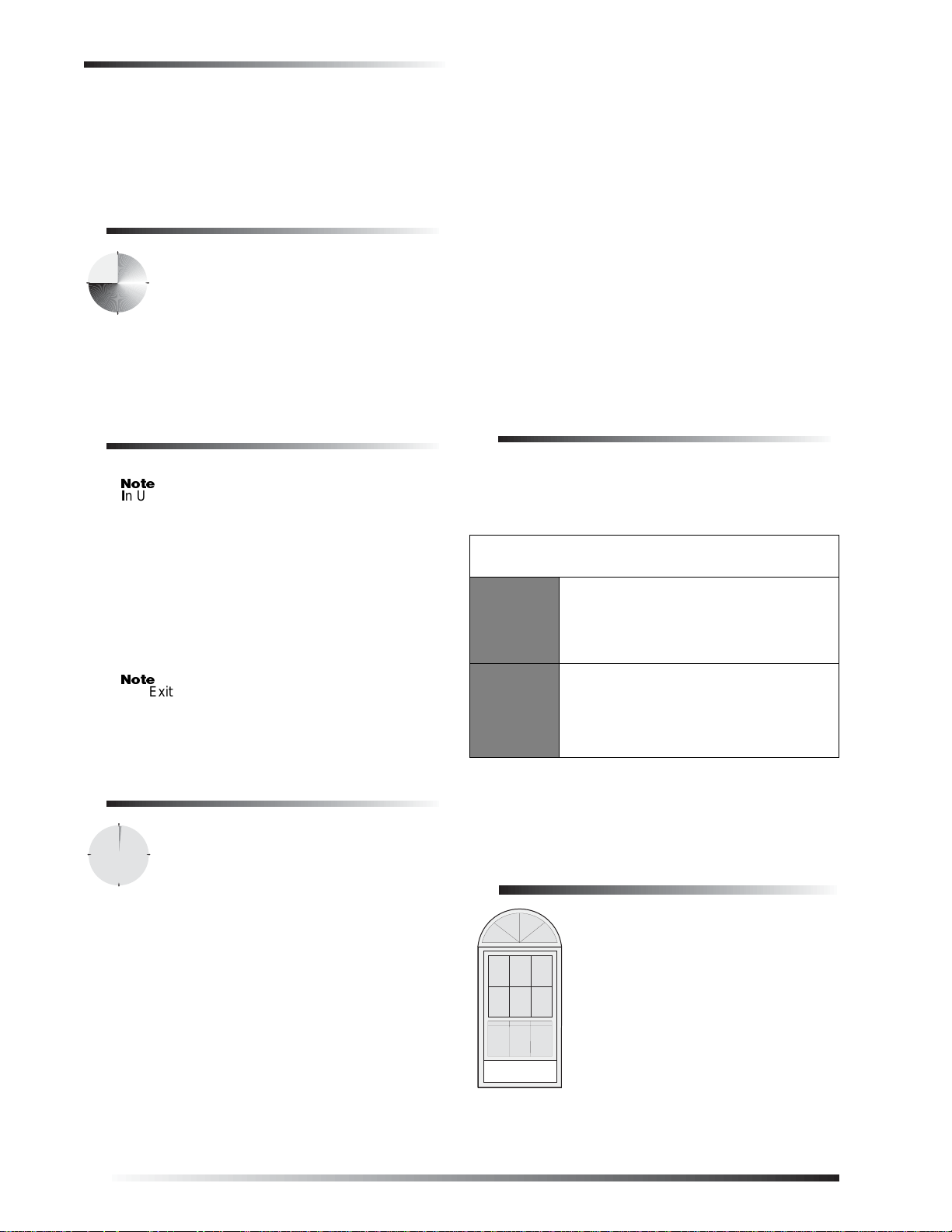
Arming While a Door or
Window is Open
It is possible to arm your system while
leaving a door or window open. This is
useful if, for example, you like to sleep at
night with the window open.
If the door or window has a sensor
installed on it, the system must be told to
ignore, or bypass, that sensor when it’s
open. All other sensors will remain active.
There are two methods for bypassing a
sensor:
Directly — After arming the system, bypass door/
window sensors before you open them. You must
6
 Loading...