

Page 1

Adve nt® Commercial
Adve nt® Commercial
Adve nt® Commercial Adve nt® Commercial System
System
SystemSystem
Document Number: 466-1767 Rev .B March 2001
Contents
ITI Part No. 60-562-01,60-562-04
User’s Manual
Welcome ...........................................................................1
System Features ...............................................................1
System Information ..........................................................2
Using the Touchpad Buttons .....................................2
Using Hand-held Touchpads .....................................4
Using Keychain Touchpads ......................................4
General Operation .....................................................4
Adjusting the Touchpad Display Brightness .............5
Adjusting the Volume of Status Messages ................5
Global Settings .................................................................6
Global Access Code ..................................................6
Area Jumping ............................................................6
Global Status and History .........................................6
Access Codes ...................................................................6
Adding an Access Code ............................................6
Guidelines ............................................................6
Deleting an Access Code .......................................... 7
Listing Codes ............................................................7
Changing an Access Code ........................................7
Changing an Access Code’s Limits ..........................8
Use Limit .............................................................8
Day Limit .............................................................8
Permanent User ....................................................8
Changing Access Code’s Authority ..........................8
User Text ...................................................................9
Authority Levels ..............................................................9
Authority Level Definitions ......................................9
Changing Authority Level Definitions ...................10
Using the Phone with the System ..................................11
Accessing the System Using an On Premise Phone 11
Accessing the System During a Phone Call .......11
Accessing the System Away from the Premise .......11
Bypassing an Answering Machine or Voice
Mail ....................................................................11
Disengaging Local Phone Control ..........................12
Adjusting the Phone Volume ..................................12
Alarms ............................................................................12
Manually Activating Alarms ..................................12
Preventing Accidental Alarms ................................13
Tips for Avoiding Accidental Alarms ................13
Cancelling an Alarm ...............................................13
Manually Resetting Hardwired Smoke Detectors ..........13
System Tampering ..........................................................13
Touchpad Access Code Tampering .........................14
Remote Phone Access Code Tampering .................14
Phone Line Tampering ............................................14
Equipment/Sensor Tampering .................................14
Security Protection .........................................................14
Turning Security Protection On ..............................14
Arming to Perimeter ..........................................14
Arming to Full ....................................................15
Arming to Night .................................................15
Arming to Silent .................................................15
Bypassing ...........................................................15
Automatically Bypassing ...............................15
Manually Bypassing .......................................15
Group Bypassing ............................................16
No Delay ............................................................16
Silent Arming .....................................................16
Turning Security Protection Off ..............................16
Using the No Activity Feature ................................16
Using Opening and Closing Reports .......................17
Open/Close Schedules .......................................17
Opening/Closing Exception Reports ..................17
Controlling Lights and Devices .....................................17
Lights ......................................................................17
Manually Turning All Lights On or Off at
Once ...................................................................17
Manually Turning One Light On or Off ............17
Brighten or Dim Lights ......................................18
Devices (Appliances) ..............................................18
Manually Turning a Single Device On and Off .18
Chime and Latchkey Features ........................................18
Chime Feature .........................................................18
Latchkey Feature .....................................................18
Automating The System Using Schedules .....................18
Schedule Types .......................................................18
Arming Schedules ...................................................19
Sunrise/Sunset Schedules ........................................19
Weekly Schedules ...................................................20
One-Time Schedules ...............................................20
Associating Lights, Devices and Access Codes
with Schedules ........................................................21
Lights and Devices .............................................21
Controlling Lights Automatically ..................21
Controlling Devices Automatically ................22
Access Code Schedules ......................................22
System Status .................................................................22
Checking the System Status ....................................22
What the Status or Trouble Beeps Mean .................22
Checking the Alarm History ...................................24
Viewing the History Buffer .....................................24
Maintaining Your System ...............................................24
Testing .....................................................................24
Automatic Test Features .....................................24
Testing the System Manually .............................24
Page 2

Testing the Phone Connection to the
Monitoring Service .........................................24
Testing Sensors/Inputs (Zones) ......................24
Testing the Panel Backup Battery ...................24
Cleaning the System Components ..........................25
Checking and Changing Batteries ...........................25
Troubleshooting ..............................................................25
Appendix A: Planning for Emergencies .........................26
Guidelines ...............................................................26
Floor Plan Example .................................................26
Your Floor Plan .......................................................26
Appendix B: System Menu Map ....................................28
Appendix C: Display Error Messages and Meanings .....29
Appendix D: System Planning Tables ............................31
Schedules .................................................................31
Holiday Schedules ...................................................31
Dealer Service Information
Dealer ____________________________________________
Representative ____________________________________________
Phone (______) ______–________
Fax (______) ______–________
Street Address ____________________________________________
____________________________________________
____________________
City
ZIP/Postal Code
_____________
State/Province
_________
E-mail ____________________________________________
Page 3

Welcome
Welcome
Thank you for selecting the Advent Commercial security
system! This system is designed to detect and respond to
various security related conditions such as door/window
sensor activation, smoke/heat detector activation, and others.
The system is simpleand easy to use via touchpad displays and buttons (and telephone touchpads).
The system is designed to tell you what you need to know
(when you need to know) and to ask for what it needs by
way of simple menu displays and selections. This method
of communication simplifies your job as a user and makes
the information in themanual complete and easy to follow.
Advent is a tremendous, user-friendly system designed to
simplify your life while providing the optimum in automated security protection.
System Features
Your security system provides several options for creating
the security and control environment you need in your
facility. How you use the system is up to you. Regardless
of the features you choose, you will find that your security
system dramatically enhances your life style.
In addition to the standard intrusion and fire system features, here are just a few of the ways you can use the special features of your security system.
Note
Some features of this security system are optional and
are availablefrom yoursecurity consultant.
Automatic Lighting Control
You can control lights inside and outside of your building
by plugging them into wireless devices called lamp m odules. These lights can then be turned on and o ff using
either the system touchpads or phones. In addition, the
system automatically turns selected lights on during an
intrusion or fire. The system automatically turns selected
lights on to scare off the intruder or to help you safely
enter/exit.
AutomaticD evice (Appliance) Control
You can control the appliances inside and outside by plugging them into wireless appliance modules. For example,
the system can be programmed to automatically turn your
coffee pot or other appliance on and off with a schedule.
Courtesy Features
The buttons on your hardwire touchpads light up when
youfirstpushabuttonandstayonfor15secondsafterthe
last button is pushed. This makes it easy to operate your
system in a dimly lit entrance area. You can adjust the
brightness of the display to a level that is comfortable for
viewing. You can als o operate your system silently. Using
this method, you can arm or disarm your system quietly
and without disturbing others.
Partitions
The system can be set up by your security consultant to
operate as a multi-partition system. This way the same system can be used to protect separate areas, with each area
having its own touchpad, sensors, sirens and so forth. Your
system can operate with up to 4 or 8 (depending on model)
separate partitions.
Areas
You can choose whether or not to treat partitions as areas.
If treated as areas:
! Zones, touchpads, schedules, programming options,
etc., belong to areas instead of partitions.
! Users may “jump” from one area to another area using
an alphanumeric touchpad.
! The word “partition” will be changed to “area” wher-
ever it is spoken, displayed, or printed.
! Users can display status for all areas in one operation
(Global Status).
Zone/Sensor Types
The sensors in your system are made up of different
“types,” and various sensor types react differently. Certain
sensors automatically trigger a call to the central monitor-
ing station immediately after being set off, or “tripped.”
Other sensors trigger a call to the central monitoring sta-
tion only after being tripped twice within a certain time
period. Some sensors react silently while others allow you
to set entry and exit delays. There are “local-only” sensors
that sound sirens at your premise but do not send a call for
help. The following are some of the useful ways you can
use various sensor types in your building.
! Monitor “Off-Limits” Areas of the Premises -Many
areas can be hazardous to children. Using local-only
sensors, you can monitor certain areas such as swimming pools. If the pool gate or door is opened,a siren
beeps. The beeping stops when the gate or door is
closed. You can also use this sensor type to alert you
to cars approaching, to monitor mailboxes so you
know when the mail arrives, and as a wireless doorbell.
! Protect Private Business Information - You can con-
trol accessibility to private documents or money
drawers. For example, sensors could be set to beep
any time the safe door is opened during business
hours. You can also assign up to 100 or 250 (depending on model) different system access codes to users.
Then, if you choose to receive opening and closing
reports from your central monitoring station, you can
check employee arming and disarming procedures. If
your system is not properly armed, you can be called.
If normal opening procedures aren’t followed, additional people can be notified.
If your building has a security gate covering the front
door and windows, you may choose to put a sensor on
the gate to sound a local siren if someone shakes the
gate to scare them away but not to call the central station. If the intruder continues to break in, other sensors protecting the front door and windows would call
the central monitoring station.
! Set Doors and Windows for Entry/Exit- Entry and exit
door sensors can be set to one of three delays, depending on how accessible your doors are to your system
touchpad or Touch-Tone
®
telephone. The delays are
set to give you enough time to get in and out of your
Advent® Commercial System
1
Page 4
System Information
building, but not allow an intruder to sneak in behind
you. You may want a short delay on the door leading
from the parking garage and a little longer delay on
the overhead garage door. You can have an even
longer delay on the driveway gate.
What Happens in an Emergency?
Your security system touchpad has three panic alarms—
police, fire, and auxiliary or m edical—that call for help
immediately. They are activated by pressing the appropriate touchpad buttons. Even very young children can learn
how to send for emergency help if needed. Police and fire
fighters will know the exact location and nature of the
emergency.
Your security system can also monitor the normal activity
for your premises and call for help automatically if normal
activities are not detected. For example, if someone falls
and can’t move, the system notices that normal activities,
such as placing outgoing calls or opening doors and windows, have not occurred for a certain length of time. Your
system sounds a low-volume siren for 5 (programmable)
minutes to let you know there may be a problem. If all is
well, you can stop the siren by disarming your system. If
no one disarms the system during the 5 minutes, your system calls for help. Refer to Appendix A, “Planning for
Emergencies” for emergency planning details.
Using the System When You’re Away
Off-siteoperations using any Touch-Tone telephone allow
you to control and monitor most of your system features
even while you are away. You can turn lights and appliances on and off, check for any trouble conditions, and
even bypass the sensor on a door to let in an employee,
delivery person, or service person.
System Information
You may have installed this security system simply to prevent break-ins and theft and to detect fires. However, your
new security system can alert you to many other emergencies. Plus, this security system lets you monitor and control conditions in your business even when you are away.
To effectively use your security system, you need to develop a few simple habits:
! Check for open doors and windows before leaving.
! Remember to gather your things and then arm your
system and exit before the exit delay time expires.
! Remember to disarm your system within the entry
delay time when you return.
! Respond to beeps, light indicators,and voice
announcements from your system, which indicate the
status of your system.
You soon become aware of the benefits these few si mple
habits bring you and help you incorporate your security
system seamlessly into your everyday l ife.
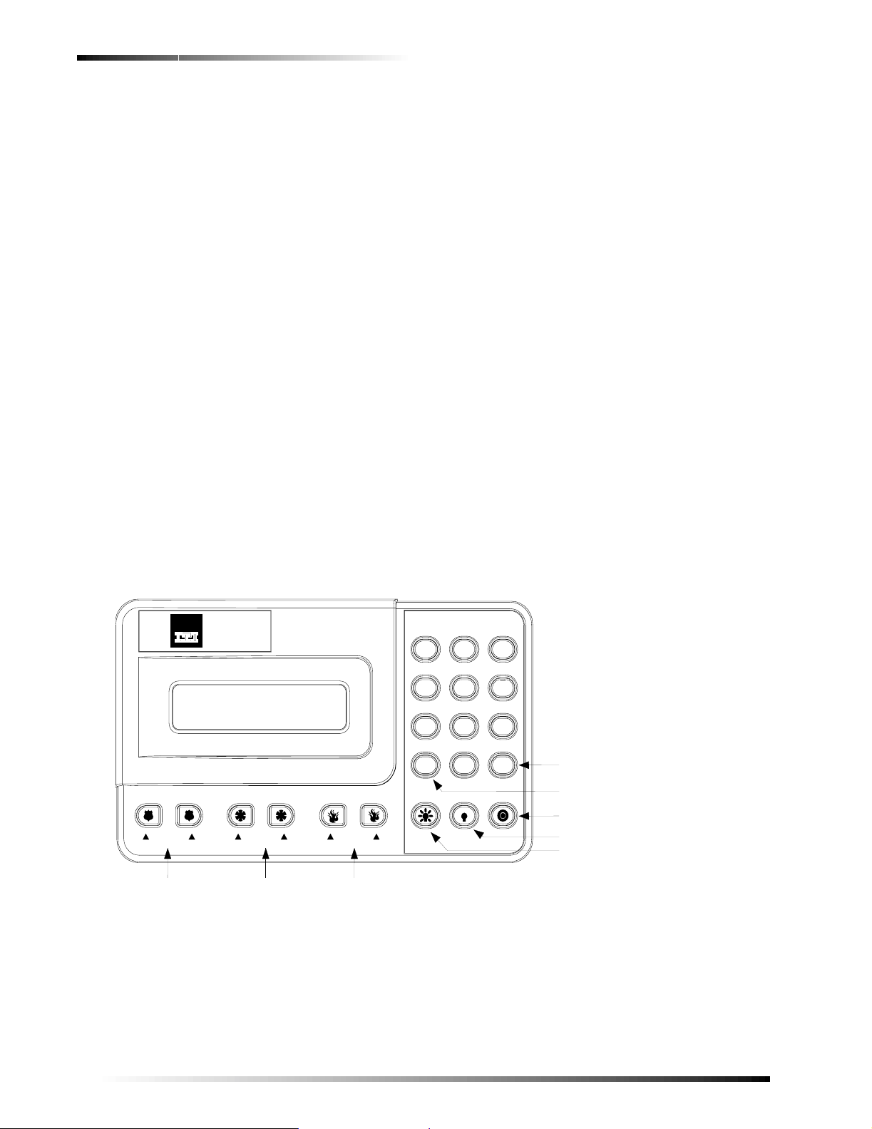
Using the Touchpad Buttons
The touchpad is the primary way to manually operate the
system or partition. Table 1 contains a list of the buttons
andwhattheydo.
Security
Automation
Fire Protection
Access Control
A BD
POLICE
POLICE
PANIC BUTTONS -- PRESS AND HOLD BOTH BUTTONS TO ACTIVATE
C
AUXILIARY
AUX/MEDICAL
E
F
FIRE
FIRE
Figure 1. Touchpad Buttons
Security
1
2
Devices
Lights
4
System
Features
7
Phone
Undo
0
*
Advent System - Test Weekly
Access
ControlSilent Arm
3
Energy
65
Scripts
98
Enter
#
IHG
1 SECURITY MENU
2 SILENT ARM MENU
3 ACCESS CONTROL MENU (NOT USED)
4 LIGHTS MENU
5 DEVICES MENU
6 ENERGY MENU (NOT USED)
7 FEATURES MENU
8 SYSTEM MENU
9 SCRIPTS MENU (NOT USED)
0 PHONE MENU
MAIN MENU OR ACCEPT
PREVIOUS MENU OR QUIT
DISPLAY BRIGHTNESS
TURN ALL LIGHTS OFF
TURN ALL LIGHTS ON
8543g114b.dsf
2
Advent® Commercial System
Page 5
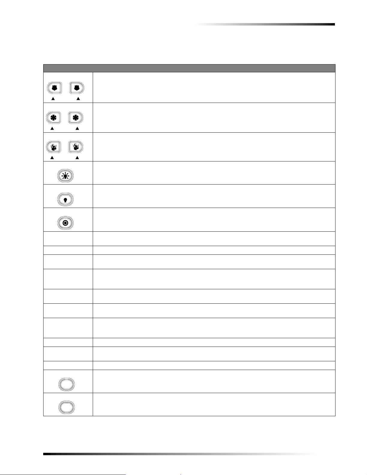
T able 1: Touchp ad Button Descriptions
Button Description
A
B
Causes police panic alarm when both buttons are pressed and held or pressed twice.
POLICE
C
D
Causes auxiliary or medical panic alarm when both buttons are pressed and held or pressed twice.
AUXILIARY
E
F
Causes fire panic alarm when both buttons are pressed and held or pressed twice.
FIRE
G
Turns all controlled lights on when held or pressed twice within 2 seconds.
H
Turns all controlled lights off when held or pressed twice within 2 seconds.
System Information
I
Controls display brightness when pressed and held.
1 Security Displays Security menu. Allows you to do security functions such as arming/disarming, bypassing, and
checking system status and alarm memory.
2 Silent Arm Displays Silent Arming menu. Provides special security functions such as silent arming/disarming.
3 Access Control
(to be developed)
Displays Access Control menu. Offers building access control functions.
4 Lights Displays Lights menu.Allows you to turn controlled lights on and off individually and assign timedlight
schedules. Lights can be turned on and off all at once by pressing the touchpad Lights On and Lights Off
buttons twice.
5 Devices Displays Devices menu. Allows you to turn non-light controlled devices such as fans and others on and
off and assign timed device schedules.
6Energy
(to be developed)
Displays Energy menu.
7 Features Displays Features menu. Allows you to turn features such as door chime on and off. Also allows you to
add, delete, or list lights and devices, change schedules, view the event log, and jump between areas (if
used).
8 System Displays System menu. Allows you to run various system tests and adjust the voice siren volume.
9 Scripts
(to be developed)
Displays Scripts menu. Allows you to record and run automatic button-press sequences (scripts). 0 Phone Displays Phone menu. Offers phone test and data communication (downloading) functions.
Undo
Cancels current operation, if any. Also returns to the previous or Main menu.
*
Enter
#
Displays Main menu if system is idle. The Main menu lists all other menus. Also enters or accepts
displayed data or selection and skips to the next selection (if any).
Advent® Commercial System
3
Page 6
System Information
S
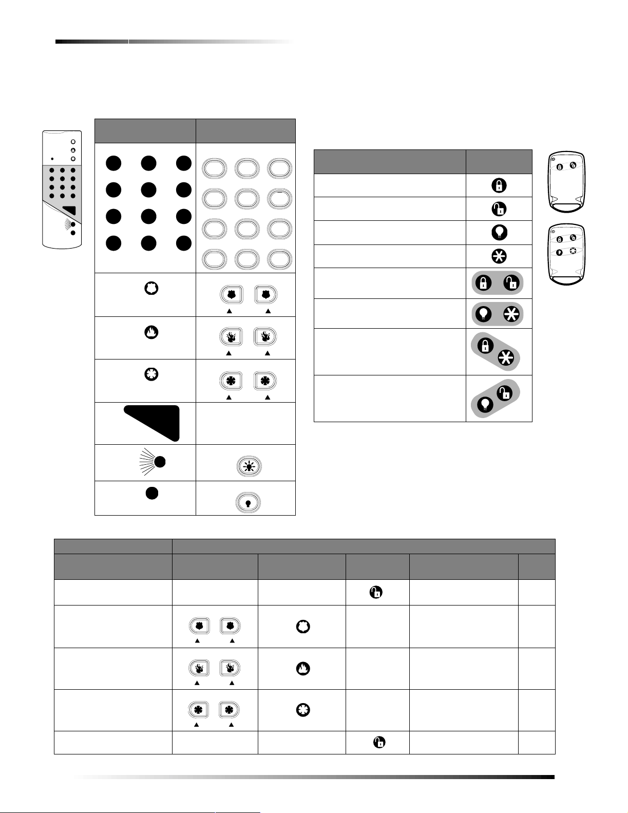
Using Hand-held Touchpads
If you have a wireless hand-held touchpad (60-597-95),
you can use it as a remote control for the system.
These Hand-held
Touchpad buttons…
O F F
O F F
S T A Y A W A Y
!
N O D E L A Y
"
#
$
C H IM E
&
%
S T A TU S
5 6
C O M M A N D
8543219A.DSF
N O D E L A Y
'
B Y P A SS
* ;
"
C H I M E
S T A T U S
5 6
%
S T A Y A W A Y
#
&
B Y P A S
* ;
!
$
'
Work like these
Touchpad buttons…
Security
1
Lights
2
Devices
4
Features
System
7
Undo
Phone
*
A
POLICE
E
FIRE
C
AUXILIARY
COMMAND
Not Used
G
H
D
B
F
Access
ControlSilent Arm
3
Energy
65
Scripts
98
Enter
#0
Using Keychain Touchpads
If you have a two- or four-button Keychain Touchpad
(60-607-319.5, 60-606-319.5), your security consultant
has customized it to do desi gnated system actions. You
mayfinditusefultowritedownwhatthebuttonshave
been set up to do.
Action Press this
button(s)…
Arm to Full (default)
_____________________________
Disarm (default) ______________
Press twice to cancel arming protests.
Turn All Lights On/Off (default)
_____________________________
Arm to next higher level (default)
_____________________________
Zone Trip (default)
_____________________________
Auxiliary Panic Alarm (default)
_____________________________
Programmable
_____________________________
Programmable
_____________________________
General Operation
In addition to automatic detection, the system also
responds to display touchpads, Touch-Tone telephones,
wireless touchpads, and other manual controls.
Table 2 shows some basic system commands and the most
common ways to perform them. For a complete dis cussion
of these, go to the page number listed.
8543164A.DSF
Action Touchpad Hand-held
Cancel an accidental alarm
Activate a police panic alarm
Activate a fire panic alarm
Activate an auxiliary panic
alarm
Disarm to OFF 1,1,
4
Table 2: Basic System Commands
Pressthisona…
Keychain
Touchpad
ACCESS CODE ACCESS CODE #, *, ACCESS CODE
A
E
C
B
POLICE
F
FIRE
D
AUXILIARY
ACCESS CODE 1, 1, ACCESS CODE #, *, 1, 1,ACCESS CODE
Touchpad
__________
optional
__________
optional
__________
optional
Phone See
#, *, 8, 8,8, 8, 8
#, *, 9, 9,9, 9, 9
#, *, 7, 7,7, 7, 7
Advent® Commercial System
Page
Page 7

Table 2: Basic System Commands (Continued)
S
Action Touchpad Han d-held
Touchpad
Arm to PERIMETER 1, 2, ACCESS CODE 1, 2, ACCESS CODE
1, 3,
Arm to FULL
Turn all lights ON
ACCESS CODE 1,3, ACCESS CODE #, *,1, 3, ACCESS CODE
Press twice
or hold for 2
seconds.
G
4, 0, #, 1
Or press 4,0, #, 1
H
4, 0, #, 2
Turn all lights OFF
Press twice
or hold.
Or press 4,0, #, 2
Manually reset smoke
8, 9,
ACCESS CODE 8,9, ACCESS CODE #, *,8, 9, ACCESS CODE
sensors
View main menus or cancel
a menu operation
Enter data
Undo
*
Enter
#
S T A T U S
5 6
B Y P A S
* ;
Pressthisona…
Keychain
Touchpad
__________
optional
Hold
Hold
Phone See
#, *, 1, 2,
ACCESS CODE
#, *, 4, 0,#, 1
#, *, 4, 0,#, 2
#, *, *
System Information
Page
Check system status 1, 9 1, 9 #, *, 1, 9
Silence trouble beeps
Undo
*
S T A T U S
5 6
#, *, *
Check alarm history 1, 0 1, 0 #, *, 1, 0
Check event history buffer 7, 5 7, 5 #, *, 7, 5
Adjusting the Touchpad Display Brightness
Both alphanumeric touchpad VFD (blue/green) display
character brightness and LCD (yellow) display back-lighting are adjustable.
To change the display character or back-lighting brightness press and hold the touchpad button
least two seconds and then release. Momentarily you will
seeitatfullbrightnessthenitstaysatthenextbrightness
level setting. Repeat this to the desired setting or to view
each of the five brightness levels from off to bright.
Note
Any alarm condition or button press temporarilysets the
display to full brightness.
I (TARGET)forat
Adjusting the Volume of Status Messages
You can change the volume of the status voice messages
from the system. There are 9 volume levels, from 0 ( silent)
to 8 (maximum).
To change the status voice m essage volume:
Steps Response
1. Press 8, 4 (from main menu).
2. Enter
0 through 8 for
desired loudness and
SYSTEM MENU; VOLUME LEVEL IS X.
TO ACCEPT PRESS # OR ENTER A
NEW LEVEL FROM
#
VOLUME LEVEL IS NOW SET TO X
press #.
0-8THEN PRESS
Advent® Commercial System
5
Page 8

Global Settings
Note
Police and Fire alarm voice messages are optionally at
full vol u me. Auxiliary and medical alarms are affected
by status voice volume.
Global Settings
Global system settings specify how the entire system behaves.
Global Access Code
There are two types of codes regarding partitions/areas.
Global access codes can be used in all partitions/areas. All
other access codes belong to the partition/area in which
they were added and cannot be used to control other partitions/areas. When a touchpad is redirected to a new partition/area, any access code used must be valid in that
partition to work.
The partition/area of an access code cannot be changed.
However,the same code may be programmed in morethan
one partition/area, with each instance of the code representing a unique user number. The panel does not allow
the user to add a duplicate code within a partition/area,
globally,or a user code which is equal to the installercod e.
Area Jumping
Normally, an Advent panel has partitions and no areas.
Your security consultant can turn your partitions into areas
which then allows you to jump between areas using the
alphanumeric touchpad. Only users with global access
codes with primary or full authority can access this.
Every tim e a jump occurs, a 4-minute timer is started.
When this timer expires, the touchpad jumps back to its
original area automatically. Also, every time the touchpad
becomes inactive, (no menu changes) a shorter, programmable time, (default 10 seconds), starts. When this timer
expires, the touchpad jumps back to its original area automatically.
To jump between areas:
Steps Response
1. Press 7, 7 (from main
menu).
2. Enter your global ACCESS
.
CODE
3. Enter the area to redirect the touchpad to.
Global Status and History
If partitions have been turned into areas, the user can also
check for global status and history. Selecting global status
allows the user to view the following:
! Arming status of all enabled areas.
! Whether any alarms are active in any enabled area.
! Whether a battery test, LED test, or download is in
progress.
FEATURES MENU; ENTER YOUR
CODE
ENTER AREA TO REDIRECT TO
THEN PRESS
STATUS PRESS
GLOBAL HISTORY PRESS
#; OR FOR GLOBAL
19#; OR FOR
75#
System displays arming
status for that area.
! All current system or area troubles.
! Status of main power, main battery, and main phone
line.
To view global s ta tus :
Steps Response
1. Press 7, 7 (from main
menu).
2. Enter your global ACCESS
.
CODE
3. Press
19, #. System displays the global
FEATURES MENU; ENTER YOUR
CODE
ENTER AREA TO REDIRECT TO
THEN PRESS
STATUS PRESS
GLOBAL HISTORY PRESS
#; OR FOR GLOBAL
19#; OR FOR
75#
status then returns to the
main menu.
Selecting global history allows the user to view the complete contents of the event history buffer, i.e. system
events and events from all areas.
To view global history:
Steps Response
1. Press 7, 7 (from main
menu).
2. Enter your global ACCESS
.
CODE
3. Press
75, #. System displays the global
FEATURES MENU; ENTER YOUR
CODE
ENTER AREA TO REDIRECT TO
THEN PRESS
STATUS PRESS
GLOBAL HISTORY PRESS
#; OR FOR GLOBAL
19#; OR FOR
75#
history then returns to the
main menu.
Access Codes
The system access codes are used to limit certain system
operations to authorized personnel. Access codes are programmable and are from four to six digits long. The system will indicate if and when an access code is required to
perform any desired function. When
played, enter the access code using the touchpad buttons.
The system automatically has one access code for the primary user in each partition/area. It is the primary access
code. You can change the primary access code, but you
cannot delete it. In addition to this primary access code,
you can create secondary access codes for other users.
Note
If you enter access codes with a partition code, all
codes added will work for that partition. If a global code
is used, all codes added will automatically be global
codes.
Adding an Access Code
Add an access code to the system whenever you want
other authorized persons to have use of the system.
Guidelines
1. Do not use sequential numbers (1234, 5678, etc.) that
can be easily defeated by unauthorized users.
2. Do not use birthdate/year combinations which others may know.
ENTERYOURCODE is dis-
6
Advent® Commercial System
Page 9

Access Codes
3. Do not use phone number sequences which others may know.
4. Keep a separate log of all programmeduser codes and their user names in a secure location.
Toaddanaccesscode:
Steps Response
1. Press 1, 8 (from main
menu).
2. Enter your primary ACCESS
.
CODE
SECURITY MENU; ENTER YOUR
CODE
ACCESS CODE MENU
3. Press 1. ENTER THE NEW CODE THEN
#
PRESS
4. Enter new
press
5. Enter new
ACCESS CODE and
#.
access code
ENTER THE CODE A SECOND
TIME THEN PRESS
CODE OK
#
again and press #.
6. Press * twice to exit. MAIN MENU
Note
No two access codes can be alike. If you are unsuccessful adding an access code, make sure the new
access code doesn’t already exist in the system. To
check the existing codes, from the main menu select 1,
access code, 3.
8, your
Deleting an Access Code
Delete an access code when you no longer want that code
to allow access to the system. To ensure maximum security, delete access codes as soon as they are no longer
needed.
To delete an access code:
Steps Response
1. Press 1, 8 (from main menu). SECURITYMENU;ENTER YOUR
2. Enter your primary ACCESS
.
CODE
3. Press 2. ENTER THE CODE TO DELETE
4. Enter the
ACCESS CODE to
delete and press #.
5. Press * twice to exit. MAIN MENU
Note
If you are unsuccessful deleting an access code, make
sure the access code exists in the system . To check the
existing codes, from the main menu select 1, 8, your
access code, 3. Also, the system w ill not let you delete
the primary access code or codes with equal or higher
authorities.
CODE
ACCESS CODE MENU
THEN PRESS
CODE DELETED
#
Note
A partition code cannot view global codes.
To list access codes:
Steps Response
1. Press 1, 8 (from
SECURITY MENU; ENTERYOURCODE
main menu).
2. Enteryourprimary
ACCESS CODE.
ACCESS CODE MENU
3. Press 3. USER # CODE XXXX NO TEXT AUTH:XLIM:X
For LIM you can have the
following options:
P = Permanent, D = Day, and
U=Use.
For AUTH, you can have the
following options:
P = Partition, F = Full, or 1-8. If
there is a * the code is a global
code.
4. Press
* twice to exit. MAIN MENU
Changing an Access Code
All access codes are not alike. When you add an access
code, you can give each access code different options.
Using the Access Code menu, you can (and should)
change the options of each new access code to ensure
maximum security.
To ensure maximum s ecurity, access codes should be
changed on a regular (monthly) basis.You should also
change an access code if you suspect an unauthorized person knows a user’s access code or if/when a user is
replaced.
To change an acce ss code:
Steps Response
1. Press 1, 8 (from main
menu).
2. EnteryourprimaryACCESS
.
CODE
3. Press 4. ENTER THE CODE TO CHANGE
4. Enter the
ACCESS CODE to
change and press #.
5. Enter the new
ACCESS CODE
and press #.
6. Enter the new
ACCESS CODE
again and press #.
7. Press * twice to exit. MAIN MENU
SECURITY MENU; ENTER YOUR
CODE
ACCESS CODE MENU
THEN PRESS
ENTER THE NEW CODE THEN
PRESS
ENTER THE CODE A SECOND
TIME THEN PRESS
CODE OK
#
#
#
Listing Codes
When listing codes, the panel displays the user number,
code, user text, limits, and authority level.
Advent® Commercial System
Note
No two access codes can be alike. If you are unsuccessful adding an access code, make sure that the new
access code doesn’t already exist in the system. To
check the existing codes, from the main menu select 1,
access code, and 3.
8, your
7
Page 10

Access Codes
Changing an Access Code’s Limits
Use Limit
Select Use Limit when the user will only need to access
the system a limited number of times such as for testing or
service personnel.
To set a Use Limit for new access codes, first add the
access codes to the system, then follow the on-screen
menu.
To set a use limit for an existing acc ess code:
Steps Response
1. Press 1, 8 (from main menu). SECURITYMENU;ENTERYOUR
2. Enter your primary ACCESS
.
CODE
3. Press 6. ENTER THE CODE TO CHANGE
4. Enter the
change and press
ACCESS CODE to
#.
5. Press 3. ENTER THE NUMBER OF USES
6. Enter the desired number of
uses and press
#.
7. Press * twice to exit. MAIN MENU
Note
When an access code with a Use Limit expires, it will
automatically be deleted.
Day Limit
Select Day Limit if a u ser will only need temporary access to the system, such as service personnel.
Note
You can not set both a Day Limit and a Use Limit for a
single access code.
To set a Day Limit for new access codes,firstaddthe
access code to the system, then follow the touchpad onscreen menu.
To set a day limit for an existing access code:
Steps Response
1. Press 1, 8 (from main menu). SECURITYMENU;ENTERYOUR
2. Enter your primary ACCESS
.
CODE
3. Press 6. ENTER THE CODE TO CHANGE
4. Enter the
ACCESS CODE to
change and press #.
5. Press 2. ENTER THE NUMBER OF DAYS
6. Enter the desired number of
days and press
#.
7. Press * twice to exit. MAIN MENU
CODE
ACCESS CODE MENU
THEN PRESS
CODE IS SET TO XXXXXX
VALID THEN PRESS
VALID FOR X USES
CODE
ACCESS CODE MENU
THEN PRESS
CODE IS SET TO XXXXXX
VALID THEN PRESS
VALID FOR X DAYS
#
#
#
#
Note
“Number of days” means the number of days starting
from today through the last da y you want the access
code to work. The access codequits working and is
deleted at midnight of the last day.
Permanent User
All new access codes are automatically permanent unless
you set a Day/Use Limit.Select PermanentUser when you
want the access code to work for an unlimited amount of
time or when you want to erase the Day Limit or Use
Limit of an access code.
To reset an ac cess code to permanent:
Steps Response
1. Press 1, 8 (from main menu). SECURITY MENU; ENTER
YOUR CODE
2. Enter your primary ACCESS
.
CODE
3. Press
4. Enter the
6. ENTER THE CODE TO CHANGE
change and press
ACCESS CODE to
#.
ACCESS CODE MENU.
THEN PRESS
CODE IS SET TO XXXXXX
#
5. Press 1. CODE SET TO PERMANENT
6. Press * twice to exit. MAIN MENU
Changing Access Code’s Authority
Each access code can have an authority level from 0 (full)
to 8 (limited). A lower number allows the use of more features and gives the user more control. A higher number
prevents the user from using some features. See Authority
Levels for more detailed information.
To set an authority level for new access codes:
Steps Response
1. Press 1, 8 (from main
menu).
2. Enter your primary ACCESS
.
CODE
3. Press 1. ENTER THE NEW CODE THEN
4. Enter the new
and press
5. Enter the new
ACCESS CODE
#.
ACCESS CODE
again and press #.
6. Press 4. AUTHORITY 1. ENTER AN
7. Enter the desired authority
level and press
#.
8. Press * twice to exit. MAIN MENU
SECURITY MENU; ENTER YOUR
CODE
ACCESS CODE MENU
#
PRESS
ENTER THE CODE A SECOND
TIME THEN PRESS
CODE OK
AUTHORITY NUMBER THEN
#
PRESS
CODE SET TO AUTHORITY X
#
8
Advent® Commercial System
Page 11

Authority Levels
To set an authority l evel for an existing access code:
Steps Response
1. Press 1, 8 (from main menu). SECURITY MENU; ENTER
YOUR CODE
2. Enter your primary ACCESS CODE. ACCESS CODE MENU
3. Press 7. ENTER CODE TO CHANGE
#
#
4. Enter the
and press
ACCESS CODE to change
#.
5. Enter the desired authority level
number (0-8) and press
#.
THEN PRESS
AUTHORITY X; ENTER AN
AUTHORITY NUMBER THEN
PRESS
CODE SET TO AUTHORITY
X
6. Press * twice to exit. MAIN MENU
User Text
Each access code can have up to 20 characters of user text
assigned to it. Th is text is used when listing codes and
when identifying a user during event printing. User text
uses the same displ ay tokens as static display text (see
Table 3) except that special tokens, such as time, date, and
flashing *, are not allowed.
When using user text you need to enter the whole string before pressing #.
Table 3: Two-Digit Display Descriptors
No. Token Text No. Token Text
00 0 24 H
01 1 25 I
02 2 26 J
03 3 27 K
04 4 28 L
05 5 29 M
05 6 30 N
07 7 31 O
08 8 32 P
09 9 33 Q
10 (undefined) 34 R
11 (undefined) 35 S
12 # (pound) 36 T
13 : (colon) 37 U
14 / (slash) 38 V
15 ? (question mark) 39 W
16 . (period) 40 X
17 A 41 Y
18 B 42 Z
19 C 43 _ (space)
20 D 44 ‘ (apostrophe)
21 E 45 -- (dash)
Table 3: Two-Digit Display Descriptors
No. Token Text No. Token Text
22 F 46 __ (underline)
23 G 47 * (star)
To change user text:
Steps Response
1. Press 1, 8. SECURITY MENU; ENTER YOUR CODE
2. Enteryourprimary
ACCESS CODE.
ACCESS CODE MENU
3. Press 0. ENTER THE CODE TO CHANGE THEN
PRESS
#
4. Enter the
ACCESS CODE
ENTER USER TEXT NUMBERS
to change and press #.
5. Enter the user text
ACCESS CODE MENU
numbers (from Table
3) then press
6. To check that you
typed the correct text
#.
Touchpad displays all listed
codes and their authorities.
press 3 to list codes.
Authority Levels
Each access code has an authority level which determines
the authority the user has to execute certain actions. There
are three pre-defined authorities and eight configurable
authorities.
Installer Authority - Can enter program mode (if partitions/areas are disarmed), gain remote access, do phone
test, do installer zone test, initiate a downloader call,
review status and event history, control lights and devices,
change installer code, change arming level within one hour
of exiting program mode. Cannot change schedules or
access codes (except own), bypass zones, extend arming
levels, change arming levels except as stated above.
Installer code is permanent.
Primary Authority - Primary user for that partition/area.
There is exactly one primary code per partition/area. This
code is permanent and cannot be restricted. Can do everything except enter program mode, do ins taller zone test,
initiate a downloader call. Primary codes are permanent.
Full Authority -
except add/delete/change/list codes of equal or higher authority.
Authority 1 to 8 - Configurable authorities. In general,
authority 1 should be the highest of the configurable authorities and authority 8 the lowest.
Authority Level Definitions
The three pre-defined and ei ght configurable authorities
allow you to carry out a specific set of actions which
require an access code and deny others. Whenever one of
these actions is requested from a touchpad, the panel
prompts you for an access code and determines whether
the entered code has sufficient authority. If not, the panel
responds with
Candoeverythingtheprimaryusercando
INVALID AUTHORITY.
Advent® Commercial System
9
Page 12

Authority Levels
When using a keyfob or keyswitch to request an arming
level change, no access code is needed and the action is
associated with a zone, not a user.
Table 4: Authority Level Actions
Auth # Parameter
I P F 1 2 3 4 5 6 7 8
10 Remote Phone Access Y Y Y CY CN CN CN CN CN CN CN
11 Arm to Level 1* X Y Y CY CY CY CY CY CY CN CN
12 Arm to Level 2 X Y Y CY CY CY CY CY CY CN CN
13 Arm to Level 3 X Y Y CY CY CY CY CY CY CN CN
14 Arm to Level 4 X Y Y CY CY CY CY CY CY CN CN
15 Arm to Level 5 N Y Y CY CY CY CY CY CY CN CN
18 Bypass Zones N Y Y CY CY CY CN CN CN CN CN
19 Bypass Critical Zones N Y Y CN CN CN CN CN CN CN CN
20 User Z one Test N Y Y CN CN CN CN CN CN CN CN
21 Phone Test Y Y Y CN CN CN CN CN CN CN CN
22 Program Schedules N Y Y CY CN CN CN CN CN CN CN
ProgramMode Y*NNNNNNNNNN
InstallerZoneTest Y$NNNNNNNNNN
Initiate Downloader Call YNNNNNNNNNN
Program Access Codes YYYNNNNNNNN
ResetSmokePower YYYNNNNNNNN
ChangeLatchkeyTime YYYNNNNNNNN
Initiate Fire Test YYYNNNNNNNN
Initiate LED Test YYNNNNNNNNN
JumpAreas NY&Y&NNNNNNNN
ControlLights YYYYYYYYYYY
ControlDevices YYYYYYYYYYY
(I = Installer, P = Primary, F = Full)
Y=Yes.
N=No.
X = Within one hour of exiting program mode.
CY = Configurable, defaulted to Yes.
CN = Configurable, defaulted to No.
* = All partitions/areas must be disarmed for installer to enter program mode.
$ = Partitions/area must be disarmed for installer to enter installer zone test.
& = Must be a global code.
Table 4 list actions and whether they are allowed or disallowed for each of the eleven authorities.
Authority Le vel
Changing Authority Level Definitions
The amount you can and cannot do within each authority
level can be changed by redefining the definitions of each
level. By changing authority definitions, you could make a
lower authority level number capable to do less or you
could make a higher authority level number capable to do
more.
10
To change definitions for authority levels:
Steps Response
1. Press 1, 8. SECURITYMENU; ENTERYOURCODE
2. Enter your primary
ACCESS CODE.
ACCESS CODE MENU
3. Press 9. ENTER AN AUTHORITY NUMBER THEN
#
PRESS
4. Enter the authority
number and press
5. Press
00, # to list
ENTER ITEM TO CHANGE THEN PRESS
#.
#
authority definitions.
6. Enter the desired
authority definition to
change and press
AUTHORITY X; ENTER THE ITEM TO
CHANGE THEN PRESS
#.
Advent® Commercial System
#
Page 13

Using the Phone with the System
Using the Phone with the System
You can accessthe system usingany touch-tone phone as a
remote control. Phone control is only available in partition
1. This section explains how to:
! Access the system using a phone at the premises.
! Access the system while away from the premises.
! Adjust the phone volume.
When accessing the system using a phone, use the keypad
to enter commands justlikean alphanumeric touchpad ora
hand-held touchpad.
Note
If you are using remoteaccess (away frompremise) and
hang up while in a menu (instead of pressing*, * to quit),
the system willautomaticallyhang up (on that end of the
line) after four minutes. If you hang u p while not in a
menu, it will automatically hang up in 30 seconds.
Accessing the System Using an On Premise Phone
To operate the s ystem using an on pre mise phone:
Steps Response
1. Pick up a Touch-T one phone. Dial tone.
2. Press
3. Enter the desired commands just as
4. Press * twice to quit and hang up.
The system answers the phone and responds to numeric commands just as it would to a system touchpad.
#, * to access the system. SYSTEM HELLO, MAIN
MENU
you would a system touchpad.
GOODBYE
Note
You can enter commands without waiting for menus to
be spoken.
Note
The otherperson on the line will not hear anything while
you access the system.
Accessing the System Away from the Premise
When you call the system, it needs to “know” when it
should answer the phone. It does this in one of two methods: Ring-Hang-Ring and Ring-Count. Contact your security consultant if you want either method enabled or
disabled or to change the number of Ring-Count rings.
To access the syst em using Ring-Hang-Ring-Method:
Steps Response
1. Pick up an off-site Touch-Tone phone and dialthe premises phone number.
2. Let the phone ring once and hang up.
3. Wait 10 to 30 seconds, dial again and wait for the system to answer.
4. Enter your ACCESS CODE. MAIN MENU
5. Enter the desired commands just as you would a system touchpad.
6. Press * twice to quit and hang up.
To operate the system using Ring Count Method:
Steps Response
1. Pick up an off-site Touch-Tone phone and dial the premises phone number.
2. Let the phone ring 12 (programmable) times and wait for the system to answer.
Dial Tone
SYSTEM HELLO.PLEASE
ENTERYOURCODE
GOODBYE
Dial Tone
SYSTEM HELLO. PLEASE
ENTER YOUR CODE
Accessing the System During a Phone Call
You can access the system when you are talking with
someone on the phone. The system puts the other person
on hold, allows system command entry as usual, and then
returns you to your call.
To interrupt a phone call:
Steps Response
1. Press #, * to put the person on hold
and to access the system.
SYSTEM HELLO,
MAIN MENU
2. Enter the desired commands just as you would a system touchpad.
3. Press * twice to quit and return to your
GOODBYE
conversation.
Advent® Commercial System
The system will answer four rings
earlier if an alarm or trouble exists.
3. Enter your ACCESS CODE. MAIN MENU
4. Enter the desired commands just as you would a system touchpad.
5. Press * twice to quit and hang up.
GOODBYE
Bypassing an Answering Machine or Voice Mail
You can access the system away from the premise if you
have an answering machine or voice mail by bypassing
them. The system requests an access code and then
responds to system commands just as it would to a system
touchpad.
11
Page 14

Alarms
To bypass an answering machine or voice mail:
Steps Response
1. Pick up an off-site Touch-Tone
Dial Tone
phone.
2. Dial the premises phone number and wait for the answering machine or voice mail system to answer.
3. Press * twice, then
# twice. SYSTEM HELLO. PLEASE
ENTERYOURCODE
4. Enter your ACCESS CODE. MAIN MENU
5. Enter the desired commands just as you would a system touchpad.
6. Press * twice to quit and hang up.
GOODBYE
Disengaging Local Phone Control
When you want to use your phone to perform other phone
operations such as banking, you will need to disengage
phone control to your security system.
To disengage local phone control:
Steps Response
1. Pick up a Touch-Tone phone. Dial Tone
2. Press #, *.
3. Press
0. PHONE MENU
SYSTEM HELLO.
4. Press 0 to disable local phone. Dial Tone
5. Make phone call.
Note
Local phone control stays disabled until th e phone is
placed back on the hook.
Adjusting the Phone Volume
When you want to adjust the phone volume to your comfort level for hearing.
To adjus t the phone volume using a phone:
Steps Response
1. Pick up a Touch-Tone phone. DialTone
2. Press #, *to access the system.
3. Press 8. SYSTEM MENU
4. Press 5 for Phone Volume. VOLUME LEVEL IS X; TO
5. Enter a new volume level and
press
# to accept.
6. Press * twice to quit and hang up.
SYSTEM HELLO,MAIN MENU
ACCEPT PRESS
ENTER A NEW LEVEL FROM
# OR
1 TO 8 THEN PRESS #
VOLUME LEVEL IS NOW SET
TO X
GOODBYE
To adjus t the pho ne volume using an off-site phone:
Steps Response
1. Pick up a Touch-T one phone. Dial Tone
2. Dial your premises phone number.
SYSTEM HELLO, PLEASE
ENTERYOURCODE
3. Enter your ACCESS CODE. MAIN MENU
4. Press 8. SYSTEM MENU
5. Press 5 for Phone Volume. VOLUME LEVEL IS X;TO
ACCEPT PRESS
ENTER A NEW LEVEL FROM
# OR
1 TO 8 THEN PRESS #
6. Enter a new volume level and
press
#.
7. Press * twice to quit and hang
VOLUME LEVEL IS NOW SET
TO X
GOODBYE
up.
Alarms
Emergency alarms notify you and the system monitoring
service in case of an emergency.Although alarms are automatically activated by the various system sensors, you can
also manually activate alarms.
When an alarm is activated, combinations of loud exterior
and interior sirens sound and a very realistic voice calls
out one of several messages, for example, Fire Alarm or
Police Alarm.
Your system has some precautionary features that allow
alarms to be validated or canceled before calling the central station. For example, when an intruder is detected,
your system soundsan alarm immediately in an attempt to
scare off the intruder. If the alarm verification feature* is
on, your system will not initiate a call to the central monitoring station unless a second sensor is activated within 4
minutes. You can also choose to delay the sounding of
exterior sirens for 15 seconds, giving you time to correct
an arming mistake or a false alarm before your neighbors
are alerted.
* - Not available in UL listed installations.
Manually Activating Alarms
Manually activate an alarm in the caseof an emergency or to test the system.
Note
Ifyouaretestingthesystem,besuretonotifythemonitoring service and instruct them not to dispatch personnel.
To manually activate an alarm:
Alarm
Type
Police
Steps
Press and
hold both
police
buttons.
You will hear this ON-OFF
(progammable) pattern…
indoor sirens outdoor sirens
steady on steady on
12
Advent® Commercial System
Page 15

Manually Resetting Hardwired Smoke Detectors
Alarm
Type
Steps
You will hear this ON-OFF
(progammable) pattern…
indoor sirens outdoor sirens
Press and
Fire
hold both
fire
___ ___ ___ ___ ___ ___
buttons.
Auxiliary
or
Medical
Press and
hold both
auxiliary
buttons.
_________
(silent)
Police(burglary) alarms activate indoor and outdoor sirens
and a police report will be sent to the monitoring service.
Fire alarms activate indoor and outdoor sirens (and strobes
if any) and a fire report will be sent to the monitoring service.
Auxiliary or medical alarms activate indoor sirens and an
auxiliary report will be sent to the monitoring service.
Panic alarms can also be programmed to be triggered
using keychain touchpads, wireless touchpads, and pendant panic buttons.
Preventing Accidental Alarms
This section explains how to avoid the surprise and annoyance of accidental alarms.
Tips for Avoiding Accidental Alarms
! Be aware of the system devices and how they operate.
! Always make sure the door is fully closed when enter-
ing and exiting the building.
! Remember to disarmthe system if you are interrupted
during the entry/exit delay time.
! Make sure all doors leading outside have delay times.
If your system is armed to PERIMETER, an alarm
will sound immediately if you open a door that is set
to instant.
! Motion detectors operate by detecting the change in
temperature when something passes in front of them.
If you have pets, you may want to eliminate motion
detectors or ask your dealer to install “pet lenses.”
! Check the location of your smoke detectors. Keep in
mind that smoke detectors canbe activated by sources
of steam, smoke, or airborne dust that can occur during normal activities.
Cancelling an Alarm
Cancelling an alarm turns off the sirens and in somecases,
also prevents the system from reporting to the monitoring
service.
! Police alarm—You must cancel the alarm within 5
(programmable) seconds to prevent the system from
reporting to the monitoring service.
! Fire alarm—Even if you cancel the alarm right away,
the system still reports to the monitoring service.
When this happens, call your monitoring service and
follow their instructions to prevent the firedepartment
from being dispatched.
! Auxiliary or medical alarm—You must cancel the
alarm within 5 (programmable) seconds to prevent the
system from reporting to the monitoring service.
To cancel an accidental alarm:
Alarm
Type
Police
Alarm
Enter your ACCESS CODE
within 5 (programmable)
seconds of the alarm start.
Fire Alarm Enter your
then follow the instructions
from your monitoring
Steps Response
ALARM CANCELED
Report canceled.
ACCESS CODE.
ALARM CANCELED.
Report continues.
service to prevent the
police or fire department
from being dispatched.
Auxiliary
or Medical
Alarm
Enter your
ACCESS CODE
within 5 (programmable)
seconds of the alarm start.
ALARM CANCELED
Report canceled.
Manually Resetting Hardwired
Smoke Detectors
Manually resetting a smoke detector following a test or
alarm resets tripped detectors. This procedure is rarely
needed because smoke detectors are automatically reset
when an alarm is acknowledged or canceled.
To manually reset tripped smoke det ectors:
Steps Response
1. Press 8, 9 (from main
menu).
SYSTEM MENU; RESET SMOKE
; ENTERYOURCODE
POWER
2. Enter your ACCESS CODE. SMOKE LOOP RESET
Note
Do not reset smoke detectors until the location of the
activated detector is determined and the smoke source
removed.
System Tampering
The system will automatically detect and indicate the type of tampering:
! Touchpad access code tampering - If set up by the
installer,four incorrect access code attempts results in
KEYSTROKE VIOLATION/police alarm.
a
! Remote phone access code tampering - Four incorrect
attempts at entering an access code results in a
indication and temporarily disables further access.
! Phone line tampering -A
TROUBLE indication results if
the phone line is cut.
! Equipment/sensor tampering - Results in a
TROUBLE
indication and/or an alarm.
TROUBLE
TAMPER
Advent® Commercial System
13
Page 16

Security Protection
Touchpad Access Code Tampering
The system can be programmed to detect four or more
incorrect access code entry attempts during any single session as unauthorized touchpad tampering. If this feature is
enabled, the system will respond with a a
TION trouble indication and a police alarm.
KEYSTROKE VIOLA-
If you know that this was done in error, contact the monitoring service and let them know.
To cancel this alarm,
Steps Response
Enter your primary
ACCESS CODE.
ALARM/REPORT CANCELED, SECURITY IS
F
OF
If canceled soon enough - within 5 seconds (programmable) - the alarm will be canceled and the report to the monitoring station stopped. If not canceled soon enough, the
monitoring service will dispatch the police. Police sirens
will sound until the alarm is canceled.
Note
To be on the safe side, call themonitoring service even
if you think you may have canceledthe false alarm in
time to stop the report.
Remote Phone Access Code Tampering
Four incorrect attempts at entering an access code during
any single operationsession resultsin a TROUBLE indication.
The system hangs up and will not allow further attempts
for 24 hours or until the system has been disarmed via an
on-site touchpad.
Hang up and wait for 24 hours and try again or follow these steps at the premises:
Steps Response
1. Press * to clear trouble indica-
Trouble beeps stop.
tion.
2. Press
1, 1, ACCESS CODE. SECURITY MENU;
SECURITYISOFF
Trouble is acknowledged and further remote phone access is allowed.
Phone Line Tampering
If the phone line is cut, the system responds with a TROUBLE indication.
To st op the tr ouble beeps:
Steps Response
Press * to clear trouble indication. Trouble beeps stop.
Note
Have the p honeline repaired immediately and notifythe
monitoring service of the situation.
Equipment/Sensor Tampering
Tampering with system equipment, sensors, etc. (for
example, opening enclosures), results in a
indication and/or an alarm.
Replace any open system enclosures or sensor covers and clear the tamper indication.
To clear a tamper/alarm indication:
Steps Response
To clear a trouble indication,
press *.
or
To clear an alarm, enter your
ACCESS CODE.
SECURITYMENU; SECURITY IS
OFF
If any covers are still open, the trouble beeps will start
again in 4 hours. The display continues displaying a flashing * until the trouble is fixed.
TAMPER TROUBLE
Security Protection
Turning Security Protection On
Turning security protection on means arming the system
against fire, intrusion, or other emergencies. You can arm
the system to one of several levels depending on your
needs throughout the day. Table 5 shows which sensors are
active in the various arming levels.
Table 5: Arming Levels
Sensors:
Indoor sensors
(motion, etc.).
Outdoorsensors
(door/window)
Environmental
sensors (smoke,
heat, carbon
monoxide, etc.).
* Arming to Night is like arming to Full, except a few desig-
nated indoor sensors remain disarmed(hallway outside your
bedroom). This would allow you to walk from your bedroom to the kitchen or bathroom at night without needing to
disarm the entire system.
Active Arming Levels:
Off Perimeter Night Full Silent
↕↕↕
↕ ↕↕↕
↕ ↕ ↕↕↕
If the phone line is still faulty,the trouble beeps will start
again within 24 hours (at the daily trouble indication
time). The display continues displaying a flashing * until
the trouble is fixed.
14
Arming to Perimeter
Arming to Perimeter is used when you stay indoors but
want security protection on all doors and windows leading
outside.
Advent® Commercial System
Page 17

Security Protection
To arm the system to perimeter:
Steps Response
1. Press 1, 2 (from main
menu).
2. Enter your
ACCESS CODE if
prompted.
SECURITYMENU;ARMING LEVEL
CHANGE
; ENTER YOUR CODE;
TO QUIT PRESS *
PARTITION/AREA X ARMED -
PERIMETER;OK TO EXIT
3. Press * twice to exit.
Active sensors:
! Outdoor (perimeter door and window) sensors that are
not bypassed.
! Environmental sensors (smoke, heat, carbon monox-
ide).
Inactive sensors:
! Indoor (motion) sensors.
Arming to Full
Arming to Full is used when you leave and no one is supposedtobeinoronthepremises.
To arm the system to full:
Steps Response
1. Press 1, 3 (from main
menu).
2. Enter your
ACCESS CODE if
prompted.
SECURITY MENU; ARMING LEVEL
; ENTERYOURCODE; TO
CHANGE
QUIT PRESS
PARTITION/AREA X ARMED - FULL;
OK TO EXIT
*
3. Press * twice to exit.
All (except bypassed) sensors will be active following an initial exit delay.
Note
Protected windows and doors must be either closed or
bypassed in order for the system to arm.
Arming to Night
Arming to Night is used when you will be staying inside— sleeping or inactive.
Note
Arming to Night is like arming to Full, except a few designated indoor sensors remain disarmed (example: hallways, certain offices, common areas). This would allow
activity limited to these areas o nly. All other areas are
fully protected.
To arm the system to night,
Steps Response
1. Press 1, 4 (from main
menu).
2. Enter your
ACCESS CODE if
prompted.
SECURITY MENU; ARMING LEVEL
; ENTERYOURCODE; TO
CHANGE
QUIT PRESS
PARTITION/AREAX ARMED - NIGHT;
OK TO EXIT
*
3. Press * twice to exit.
All sensors will be active except those that are bypassed
and those designated indoor sensors preset by your security consultant.
Note
Protected windows and doors must be either closed or
bypassedinorderforthesystemtoarm.
Arming to Silent
Arming to Silent is the same as arming to full except police alarms are silent.
To arm the system to silent:
Steps Response
1. Press 1, 5 (from main
menu).
2. Enter your
ACCESS CODE if
prompted.
SECURITY MENU; ARMING LEVEL
; ENTERYOURCODE; TO
CHANGE
QUIT PRESS
PARTITION/AREA X ARMED -
SILENT;OK TO EXIT
*
3. Press * twice to exit.
All (except bypassed) sensors will be active following an initial exit delay.
Note
Protected windows and doors must be either closed or
bypassedinorderforthesystemtoarm.
Bypassing
A security system cannot protect an open door or window.
When you attempt to turn security protection
ON, the sys-
tem will warn you if a door or window has been left open.
However, you may want to arm the system anyway. To do
this, you must bypass the open door or window. You can
do this automatically for just this time or manually for
more than just this time.
Automatically Bypassing
When you cannot turn security protection on because the
system warns you about an open door/window or faulty
door/window sensor.
To bypass a door or window for this arming se ssion only:
Steps Response
1. Press 1, (desired arming
level 1-5),
ACCESS CODE.
2. Press 1 to accept open
SECURITY MENU; ZONE ### IS
; PRESS 1 TO ACCEPT
OPEN
ZONE ###BYPASSED
sensor.
The sensor stays ignored (bypassed) only until you disarm the system.
Note
See Manually Bypassing an Open Window or Door for
bypassing windows or doorsfor more than just thisone
time.
Manually Bypassing
If the system consistently warns you about the same open
door/window or a faulty door/window sensor, you may
want to indefinitely bypass that zone until it can be fixed.
Advent® Commercial System
15
Page 18

Security Protection
To bypass a door or window indefinitely:
Steps Response (if any)
1. Press 1, 7 (from main menu). SECURITYMENU;ENTER YOUR
CODE
2. Enter your ACCESS CODE. ENTER THE ZONE NUMBER
#; TO LIST
0#
3. Enter the desired sensor
THEN PRESS
BYPASSED ZONES PRESS
ZONE X BYPASSED
number to be bypassed and
# (ENTER).
press
The sensor stays bypassed until you unbypass the sensor using the same method.
Group Bypassing
This allows you to manually bypass a group of zones. A
bypass group and all zones in that group automatically
belong to the same partition or area.
Ask your installer about setting up a bypass group.
To group bypass a group of sensors indefinitely:
Steps Response (if any)
1. Press 1, 7 (from main menu). SECURITY MENU; ENTER YOUR
CODE
2. Enter your ACCESS CODE. ENTER THE ZONE NUMBER
#
3. Press
90, the desired group
number to be bypassed and
THEN PRESS
GROUP X BYPASS COMPLETE;
MAIN MENU
then # (ENTER).
To group unbypass a group of sensors indefinitely:
Steps Response (if any)
1. Press 1, 7 (from main menu). SECURITYMENU;ENTER YOUR
CODE
2. Enter your ACCESS CODE. ENTER THE ZONE NUMBER
#
; MAIN MENU
3. Press
91, the desired group
numberto be unbypassedand
# (ENTER).
then
THEN PRESS
GROUP X UNBYPASS
COMPLETE
No Delay
Arming modifiers s uch as
NO DELAY and LATCHKEY can be
added once the system arming level is entered.
When you want to arm the system with no entry delay.
To arm with no entry delay:
Steps Response (if any)
Press 1, (desired arming level
SECURITY MENU; NO DELAY
1-5), enter ACCESS CODE if
prompted, and then 9.
The system will arm as usual but without the normal entry delay.
Note
Do not use this no delay feature if you have to open a
protected door in order to enter.
Silent Arming
The Silent Arming menu is used to arm or disarm your
system without disturbing anyone with status beeps or
voice messages. This works the same as the security menu
for arming or disarming the system with one exception:
2 (silent arm menu) instead of 1 (security menu) to
press
access the silent arming menu. For example:
To silent arm the sy stem to full:
Steps Response
1. Press 2, 3 (from main
menu).
2. Enter your
ACCESS CODE if
prompted.
SILENT ARMING MENU;ARMING
LEVEL CHANGE
; TO QUIT PRESS *
CODE
PARTITION/AREAX ARMED - FULL;
OK TO EXIT
; ENTER YOUR
3. Press * twice to exit.
Note
Protest beeps will still sound.
Toturn on the status beeps and voice messages again, arm
or disarm the system using the security menu as usual.
Turning Security Protection Off
Arming to OFF is used when security is not a concern. This
would be when the premises is occupied and people will
be going both inside and out.
To turn system arming off:
Steps Response
1. Press 1, 1 (from main
menu).
2. Enter your
ACCESS CODE if
prompted.
SECURITY MENU; ARMING LEVEL
CHANGE
; ENTERYOURCODE;
TO QUIT PRESS *
PARTITION/AREA X SECURITYIS
OFF
3. Press * twice to exit.
Sensors that will remain active:
! Environmental sensors (smoke, heat, carbon monox-
ide).
Sensors that will be inactive:
! Indoor sensors.
! Perimeter sensors such as doors and windows.
Using the No Activity Feature
The sy stem can monitor the activity at the premises and
automatically call for help if normal activities are not
detected within a defined period of time.
For example, if someone falls and can’t move, the system
will detect that normal activities, such as placing outgoing
calls or opening doors andw indows, havenot occurredfor
a predetermined No Activity time.
The system sounds a low-volume auxiliary alarm to let
you know there may be a problem. If all is well, you can
stop the siren by disarming your system. If the system is
not disarmed within 5 minutes, it calls the central monitor-
16
Advent® Commercial System
Page 19

Controlling Lights andDevices
ing station. The central monitoring station will send emergency personnel to the premises to check out the situation.
Note
Contact your security consultant to enable or di sable
this feature.
Using Opening and Closing Reports
Opening and Closing Reports allows pagerholders, system
printer (if any), and the central station to be notified whenever the system is armed and/or disarmed.
Opening and closing reports occur without special user
input and without regard to any time schedule.
Whenever the system is disarmed, an opening report is
paged, printed, or reported to the monitoring service. For
example,
CODE
Whenever the system is armed, a closing report is paged,
printed, or reported. For example, NORMAL CLOSING,[SOURCE
DEVICE TEXT OR ID
If so programmed, opening and closing reports (as well as
all other system event s) are automatically recorded in the
system history buffer. See Checking the History Buffer
section for details.
The system can also be set up to report if an opening or closing occurs outside a set schedule.
Open/Close Schedules
To define an open/close window in a partition for a given
day,exactly two open/close schedules must be valid on
that day. When neither schedule is on, the partition/area is
expected to be closed. After one schedule turns on the partition is expecting an opening. When both schedules are
on, the partition/area is expected to be open. When the
other schedule is off, the partition/area is expecting a closing. As soon as both schedules are off again, the partition/
area is expected to be closed again.
Opening/Closing Exception Reports
The opening and closing exception reports feature allows
programmed pagerholders and/or the central station to be
notified when arming or disarming occurs outside of specified time schedules.
When the system d etects an opening or closing arming
change that is early, normal, or late, it reports t he arming
change as such. If the system cannot classify an abnormal
arming change as early or late, it reports a generic exception. If at the end of an opening or closing time window,
the partition/area is not open or closed, respectively, the
NORMAL OPENING,[SOURCE DEVICE TEXT OR ID], [USER
], [PARTITION/AREA NUMBER].
], [USER CODE], [PARTITION/AREA NUMBER].
Note
Contact your security consultantif you would like to turn
opening and closingreports on or off for any programmed pager, system printer, or for the monitoring
service reporting.
system reports that the partition/area failed to open or
close.
Here are two specific examples o f how opening and closing exception might be used in a business setting:
! Every morning you’d like to be notified if your busi-
ness is disarmed after its normal opening time.
! Every evening you’d like to be notified if your busi-
ness is armed before its normal closing time.
The most typical setup of this feature makes use of both
exception opening and exception closing. (However, it is
possible to use only exception opening or only exception
closing.)
Follow the detailed procedure defining opening and closing schedules located in the Setting Weekly Schedules section.
Note
Contact your security consultantif you would like to turn
the exception reporting on or offfor any particular pager,
system printer, or for the central station.
Controlling Lights and Devices
Lights
Lights controlled by the system can be turned on and off
manually or automatically. See Automating the System
Using Schedules for details on controlling lights automatically.
Note
Contact your security consultant for adding or removing
controlled lights.
Manually Turning All Lights On or Off at Once
To turn all controlled lights on or off:
Steps Response
1. Press G (on bulb) twice rapidly. ON
2. Press H (off bulb) twice rapidly. OFF
or
Steps Response
1. Press 4, 0#. ENTER A LIGHT NUMBER THEN
2. Press
1 (for on) or 2 (for off). LIGHTS ARE NOW ON/OFF
Note
Turning off all lights turns off all devices as well.
Manually Turning One Light On or Off
When turning selected lights on or off, you will also be able to brighten or dim them.
PRESS
#; ALL LIGHTS MENU;
TO TURN ON NOW PRESS 1;
TO TURN OFF NOW PRESS 2
Advent® Commercial System
17
Page 20

Chime and Latchkey Features
To tur n selected controlled lights on or off:
Steps Response
1. Press 4. ENTER A LIGHTNUMBERTHEN
PRESS
#
2. Enter the desired light num-
ber then press #.
3. Press
4. Press
1 (for on) or 2 (for off).
* twice to exit. MAIN MENU;GOODBYE
XISON/OFF; LIGHT MENU; TO
TURN ON NOW PRESS
TURN OF NOW PRESS
1; TO
2
Brighten or Dim Lights
To brighten or dim selected co ntrolled lights:
Steps Response
1. Press 4. ENTER A LIGHTNUMBERTHEN
#
PRESS
2. Enter the desired light number then press
#.
XISON/OFF; LIGHT MENU
3. Press either 4 or 5 repeatedly to brighten or dim light.
4. Press * twice to exit.
MAIN MENU; GOODBYE
Devices (Appliances)
Just like lights, devices (appliances) controlled by the system can also be turned on and off manually or automatically according to a preset schedule. See Automating the
System Using Schedules for details on controlling devices
automatically.
Manually Turning a Single Device On and Off
To turn selected controlled devices on or off:
Steps Response
1. Press 5 (desired device number), #.
2. Press
1 for on or 2 for off. ON/OFF
DEVICE MENU,[DEVICE NAME].
your se curity consultant.
Latchkey Feature
The latchkey feature pages you if someone doesn’t arrive
at the premises and disarm the s ystem by a designated
time.Ifprogrammedtodoso,thesystemwillalsophone
in a report to the monitoring service. The latchkey time
need only be set to the desired time once.
To set the latchkey time:
Steps Response
1. Press 7, 2 (from main menu). FEATURES MENU; PRESENT
LATCHKEY TIME
2. Press # to accept the indi-
NEW LATCHKEY TIME
cated time or enter the new
[desired time] (for example,
440 for 4:40), #.
3. Press 1 for A.M.or2 for P.M. A.M. or P.M.
Arm the system to full adding the latchkey arming modifier:
Steps Response
Press 1, 3, ACCESS CODE (if
requested), 8.
SECURITY MENU;AWAY,
LATCHKEY
Automating The System Using Schedules
Schedules are used to automatically controlthe system ata
predetermined day and time. Schedules can be used for
automatically turningsystem controlled lights and devices
on or off. They can automatically arm o r disarm the system and also define time periods during which business
type openings, closings, and access codes are valid.
Each system partition/area (separate protected area) can
have up to 32 programmed (numbered) schedules. All
schedules belong to a partition/area; there are no global
schedules.
Note
Contactyour security consultant for adding or removing
controlled devices.
Chime and Latchkey Features
Chime Feature
The chime feature will alert you whenever someone enters
or leaves through a perimeter door. This may be used, for
example, during a party to announce arriving guests or
during the day to announce exits and entries.
To turn the chime feature on or off:
Steps Response
Press 7, 1 (from
main menu).
Note
To change which doors (or other selected sensors)
chime or what text message is indicated(if any),contact
18
FEATURES MENU, CHIME ON (if off) or
CHIME OFF (if on).
Each schedule also has an arming type defining what arming actions, if any, are taken at a schedule transition. The
daylight type determines whether the schedule is used in
type defining whether on or off-times are adjusted daily
based on variations in sunrise or sunset. The daylight type
also determines whether thepanel is the in the Northern or
Southern hemisphere.
Schedule Types
Every schedule is defined to be either valid or invalid during four different s chedule types in a given partition/area.
The types are:
! Type 1 (Normal) is valid whenever it is not a holiday
and the schedule condition is not temporary.
! Type 2 (Holiday A) is valid when the current date
matches a holiday date programmed in the Holiday A
list. This list is pre-programmed by the installer. A
holiday condition is overridden by a temporary condition.
Advent® Commercial System
Page 21

! Type 4 (Holiday B) is valid when the current date
matches a holiday date programmed in the Holiday B
list. This list is also pre-programmed by the installer.
A holiday condition is overridden by a temporary condition.
! Type 8 (Temporary) is valid during a temporary con-
dition which has been turned on by the user via the
Schedule Menu. It will stay there until the temporary
condition is canceled by the user. The temporary condition overrides all other conditions.
Any schedule can be defined to be valid in any combination of these conditions. When the schedule is defined in
the Schedule Menu, the user is prompted for the schedule
type. To determine the type, give each condition the
numerical value in parentheses above and add up the values. For example, if a schedule should be valid under normal and holiday B conditions, the schedule type is 5 (see
Table 6).
Appendix D has a table to list and keep track of all your
programmed schedule conditions and options. Refer to
Tables 12 and 13 in Appendix D to list all your programmed Holidays.
Note
Only your installer can program the holiday list
Table 6: Schedule Types
Schedule
Type
Conditions
1Normal
2 Holiday A
3 Normal + Holiday A
4 Holiday B
5 Normal + Holiday B
6 Holiday A + Holiday B
7 Normal + Holiday A + Holiday B
8Temporary
9 Normal + Temporary
10 Holiday A + Temporary
11 Normal + Holiday A + Temporary
12 Holiday B + Temporary
13 Normal + Holiday B + Temporary
14 Holiday A + Holiday B + Temporary
15 Normal + Holiday A + Holiday B + Temporary
Arming Schedules
Besides a schedule type, every schedule also has an arming type. Table 7 defines the valid arming types. To keep
scheduled arming simple, only one arming schedule
should be defined on a given day .
Automating The System Using Schedules
Table 7: Arming Types
Arming
Type
Arming Acti on
for On-
Transition
ArmingAction
for Off-
Transition
Opening/
Closing
Schedule
0 None None No
1Disarm Arm No
2 Arm Disarm No
3 Arm None No
4 Disarm None No
5None Arm No
6None Disarm No
7 None None No
8 None None Yes
9Disarm Arm Yes
10 Arm Disarm Yes
11 Arm None Yes
12 Disarm None Yes
13 None Arm Yes
14 None Disarm Yes
15 None None Yes
Sunrise/Sunset Schedules
Schedule on- or off-times may be tied to the daily variations in sunrise and sunset. Each midnight, sunrise/sunset
schedules are adjusted based on the change in sunrise or
sunset times. The amplitude of the variations is based on
the programmed latitude. When programmed, each schedule is assigned a daylight type. Table 8 defines the daylight
types.
Table 8: Daylight Types
Daylight
Type
Sunrise/Sunset
Adjustment for
On-Transition
0 None None North
1 None None South
2 Sunset Sunrise North
3 Sunset Sunrise South
4 Sunrise Sunset North
5 Sunrise Sunset South
6 Sunset None North
7 Sunset None South
8 Sunrise None North
9 Sunrise None South
10 None Sunset North
11 None Sunset South
12 None Sunrise North
Sunrise/Sunset
Adjustment for
Off-Transition
Hemisphere
Advent® Commercial System
19
Page 22

Automating The SystemUsing Schedules
Table 8: Daylight Types (Continued)
Daylight
Type
Sunrise/Sunset
Adjustment for
On-Transition
Sunrise/Sunset
Adjustment for
Off-Transition
Hemisphere
13 None Sunrise South
14 Sunset Sunset North
15 Sunset Sunset South
16 Sunrise Sunrise North
17 Sunrise Sunrise South
! Weekly schedules are repeatedly used on certain times
and days of the week. These schedules remain active.
! One-Time schedules are those that are used only once
at a set on- and off-time and then automatically made
inactive by the system.
Any schedule can be defined to b e a w eekly schedule. For
a weekly schedule, the user defines on what days of the
week the schedule is valid. A weekly schedule must havea
valid on-time and a valid off-time. These times define
when the schedule shouldturn on and off and are the same
for every day of the week. If the off-time is earlier than the
on-time, then the off-time is assumed to be for the next
For example, if a schedule on-time should vary with the
daily sunset time but the scheduled off-time should be
constant,then the scheduledaylight type is 6. Or, if the onand off-times should both track with the sunset and the
panel is in the Southern Hemisphere, the daylight t ype is
15.
day.
Any automatic actions (lights, devices, access codes) set to
use this weekly schedule will repeatedly activate on the
days and times set.
To set a weekly schedule:
Weekly Schedules
There are two similar,but different scheduletypes: weekly and one-time.
Steps Response
1. Press 7, 4 (from main menu). FEATURESMENU; ENTER YOUR CODE
2. Enter your primary ACCESS CODE. SCHEDULES ARE NORMAL;ENTER A SCHEDULENUMBER THEN PRESS # OR TO LIST
3. Enter the desired schedule number and
press
#.
Enter desired number(s), and then #.
1-Monday
2-Tuesday
3 - Wednesday
4-Thursday
5-Friday
6-Saturday
7-Sunday
8-Addalldays
9 - Remove all days
0 - One time schedule
4. Enter the time you want your schedule to start and press #.
5. Press
1 or 2. ON TIME IS NOW XX:XX AM/PM;NO OFF TIME TO ACCEPT PRESS #OR ENTER A NEW OFF TIME
6. Enter the time you want your schedule to
end and press
7. Press
1 or 2. OFFTIMEISNOWXX:XX AM/PM;
#.
8. Enter the desired schedule type number
then press
# (see Table 6).
9. Enter the desired arming schedule option
number (0-15) then press
# (see Table 7).
10. Enter the desired schedule daylight option
number (0-17) then press
# (see Table 8).
SCHEDULES PRESS
SCHEDULE VALID ON NO DAYS;TO ACCEPT PRESS # TO ADD XXX (days) PRESS X (the days
0#OR TO ENABLE TEMPORARY SCHEDULES PRESS 00 #
number);TO CHANGE TO A ONE TIME SCHEDULE PRESS 0; FOR A DIFFERENT SCHEDULE
*
PRESS
SCHEDULE IS WEEKLY;NO ON TIME;TO ACCEPT PRESS # OR ENTER A NEW ON TIME THEN
#; FOR NO ON TIME PRESS 0#;TO CHANGE THE DAYS OF THE WEEK PRESS *
PRESS
Note
The system will automatically make it a weekly schedule if you don’t
select the one-time schedule (0) option.
FOR AM PRESS 1 FOR PM PRESS 2 TOCHANGETHEONTIMEPRESS*
THEN PRESS
FOR AM PRESS 1 FOR PM PRESS 2 TO CHANGE THE OFF TIME PRESS *
SCHEDULE TYPE IS 0 TO ACCEPTPRESS # OR ENTER A NEW SCHEDULETYPE THEN PRESS #
SCHEDULE IS NOW TYPE X TO ACCEPT PRESS # TO ENTER A NEW SCHEDULE TYPE PRESS *;
SCHEDULE ARMING OPTION IS 0 TO ACCEPT PRESS # TO ENTER A NEW SCHEDULE ARMING
OPTION THEN PRESS
SCHEDULE ARMING OPTION IS NOW X TO ENTER A NEW SCHEDULE ARMING OPTION PRESS *
SCHEDULE DAYLIGHT OPTION IS X TO ACCEPT PRESS # TO ENTER A NEW SCHEDULE
DAYLIGHT OPTION PRESS
SCHEDULE DAYLIGHT OPTION IS NOW X TO CHANGESCHEDULE DAYLIGHT OPTION PRESS *
# FOR NO OFF TIME PRESS 0#
#
*
Your schedule is then displayed in its entirety.
20
Advent® Commercial System
Page 23

Steps Response
11. Press * twice to exit.
Automating The System Using Schedules
One-Time Schedules
One-time schedules work the same way as weekly schedules, except that they are only valid once and not on cer-
the schedule turns off. One-time schedules are automatically made inactive at the scheduled off-time setting.
To set a one-time schedule:
tain days of the week. The schedule type is set to 0 when
Steps Response
1. Press 7, 4 (from main menu). FEATURES MENU;ENTERYOURCODE
2. Enter your primary ACCESS CODE. SCHEDULES ARE NORMAL;ENTER A SCHEDULE NUMBER THEN PRESS # OR TO LIST
0#OR TO ENABLE TEMPORARY SCHEDULES PRESS 00 #
3. Enter the desired schedule number and
press
#.
4. Press
0, (to make it a one-time schedule),
and then #.
SCHEDULES PRESS
SCHEDULEVALID ON NO DAYS; TO ACCEPT PRESS # TO ADD XXX (days) PRESS X (the days
number); TO CHANGE TO A ONE TIME SCHEDULE PRESS 0; FOR A DIFFERENT SCHEDULE
*
PRESS
SCHEDULE IS ONE TIME; NO ON TIME; TO ACCEPT PRESS # OR ENTER A NEW ON TIME THEN
#; FOR NO ON TIME PRESS 0#;TO CHANGE THE DAYS OF THE WEEK PRESS *
PRESS
1-Monday
2-Tuesday
3 - Wednesday
4-Thursday
5-Friday
6-Saturday
7-Sunday
8-Addalldays
9 - Remove all days
0 - One time schedule
5. Enter the time you want your schedule to
start and press
6. Press
1 or 2. ON TIME IS NOW XX:XX AM/PM;NO OFF TIME TO ACCEPT PRESS #OR ENTER A NEW OFF TIME
#.
7. Enter the time you want your schedule to
end and press
8. Press
1 or 2. OFFTIMEISNOWXX:XX AM/PM;SCHEDULE TYPE IS 0 TO ACCEPT PRESS # OR ENTER A NEW
#.
9. Enter the desired schedule type number
then press
# (see Table 6).
10. Enter the desired arming schedule type
number then press
# (see Table 7).
11. Enter the desired schedule daylight option
number then press
12. Press
* twice to exit.
# (see Table 8).
FOR AM PRESS 1 FOR PM PRESS 2 TO CHANGE THE ON TIME PRESS *
THEN PRESS
FOR AM PRESS 1 FOR PM PRESS 2 TO CHANGE THE OFF TIME PRESS *
SCHEDULE TYPE THEN PRESS
SCHEDULE IS NOW TYPE X TO ACCEPT PRESS # TO ENTER A NEW SCHEDULE TYPE PRESS *;
SCHEDULE ARMING OPTION IS 0 TO ACCEPT PRESS # TO ENTER A NEW SCHEDULE ARMING
OPTION THEN PRESS
SCHEDULE ARMING OPTION IS NOW X TO CHANGESCHEDULE ARMING OPTION PRESS *
SCHEDULE DAYLIGHT OPTION IS X TO ACCEPTPRESS # TO ENTER A NEW SCHEDULE
DAYLIGHT OPTION PRESS
SCHEDULE DAYLIGHT OPTION IS NOW X TO CHANGE SCHEDULE DAYLIGHT OPTION PRESS *
# FOR NO OFF TIME PRESS 0#
#
#
*
Your schedule is then displayed in its entirety.
Associating Lights, Devices and Access Codes with Schedules
The association of schedules with lights, devices, and
access codes are programmed in the Light Menu, Device
Menu, and Access Code Menu, respectively.
Lights and De vices
Each valid menu output can be associated with any of the
schedules in its partition/area. Whenever a transition of an
associated schedule occurs, the state of the output is
Advent® Commercial System
reevaluated. All schedule transitions occur at minute
boundaries. The following rules apply:
! If any associated schedules turn on, the output is
turned on.
! If any associated one-time schedule turns off, the out-
put is turned off. This occurs even if other associated
schedules are still on.
! If any associated weekly schedule turns off and there
are no associated schedules on, the output is turned
off. If any other associated schedules remain on, the
output is unchanged.
21
Page 24

System Status
Some general rules are that on-transitions have priority
over off-transitions, and one-time schedules have priority
over weekly schedules. Also, user-initiated changes (i.e.
an output state change via a touchpad) have priority over
scheduled changes, so that when an output is turned on or
off by a user its state does not change back until the next
valid schedule transition.
Controlling Lights Automatically
The sy stem can be programmed to turn lights controlled
by the system on and off automatically according to a preset schedule.
To set up a light schedule
Steps Response
1. Press 4, (desired light num-
LIGHTS MENU,[LIGHT NAME]
ber), #.
2. Press
3, (desired schedule
number(s)),
0, #.
SCHEDULE NUMBER
Controlling Devices Automatically
Just as the system can be programmed to control lights
automatically, it can control devices (appliances) automatically as well.
To set a device schedule:
Steps Response
1. Press 5, (desired device
number),
2. Press
#.
3, (desired schedule
DEVICE MENU,[DEVICE NAME].
SCHEDULE NUMBER.
number), 0, #.
Access Code Schedules
Each valid access code except those which can never be
disabled (installer and primary codes) can be associated
with any ofthe schedules in its partition. Global codes, i.e.
those valid in all partitions, can only be associated with
schedules in partition1. When a transition of an associated
schedule occurs, nothing happens to the access code.
Rather, the validity of an access code is determined when
the code is being used. When a user is prompted for a
code, the system checks whether any schedules are tied to
the code. If so, the code is valid whenever any of it s associated schedules is on and invalid if all of its associated
schedules are off.
To change an acc ess code’s schedule:
Steps Response
1. Press 1, 8 (from main
menu).
SECURITY MENU; ENTER YOUR
CODE
2. Enter your ACCESS CODE. ACCESS CODE MENU
3. Press 5. ENTER THE CODE TO CHANGE
#
#
0#
4. Enter the
change and press
ACCESS CODE to
#.
5. Enter the schedule number
and press
6. Press
#.
0, #. CODE SET TO X
THEN PRESS
CODE SET TO X SCHEDULE;
ENTER A SCHEDULE THEN
PRESS
SCHEDULE X ADDED; TO
ACCEPT PRESS
7. Press * twice to exit.
System Status
Your system has been designed to keep false alarms and
system problems to a minimum. If thereis a problem, your
security system can diagnose it and then sound trouble
beeps to let you know about it. In most instances, your
system can alert your central monitoring station of the
problem as well.
Checking the System Status
When you want to know the current status of the system
including its arming state and any current problems.
To check the system status:
Steps Response
1. Press 1, 9. SYSTEM MENU; CHECK STATUS
2. Press UNDO (*) to quit. GOODBYE
What the Status or Trouble Beeps Mean
Your Advent system’s alphanumeric touchpads, interior
sirens and speakers use status and trouble beeps to communicate what the system is doing or if there isa problem.
You will hear some sounds each time you tell your system
to do something. Some will only sound when the system
protests in some way . Table 9 describes the operating and
trouble beeps you may hear from your system.
22
Advent® Commercial System
Page 25

Table 9: Status and Trouble Beeps
Type of Sound Sound Pattern What These Sounds Mean
When YouArm or
Disarm
When You Enter
or Exit
1 short beep
2 short beeps
3 short beeps
1 long, 1 short beep
1 long, 2 short beeps
3 short beeps every 2 seconds
Your system disarmed to OFF.
Your system armed to PERIMETER.
Your system armed to FULL.
Your system armed to NIGHT.
Your system armed to SILENT.
Your system is armed and the exit delay is in progress. (Beeps sound once
per second during the last 10 seconds.)
Or
3 short beeps every second
Your system is armed and the entry delay is in progress.
Your system is armed, an alarm has occurred, the alarm sirens have already
“timed out,” and the entry delay is in progress.
Chime Feature On 2 short beeps (or “ding-dong”
sound)
Protest Beeps 1 long, 1 short beep
continuous sequence. Once
per second.
Your system is OFF. The chime feature is on, and an exterior sensor like a
door or window is opened.
Your are trying to arm with one of the many possible protest conditions
present. You will be asked if you want to accept the protest condition after
you enter your code.
For example, you are trying to arm to PERIMETER or FULL with an
exterior door or window open. Close the door or window or see section
“Arming with a Door or Window Open.”
or
You are trying to disarm after an alarm has occurred and the alarm sirens
have already “timed out.”
System Trouble
Beeps
6 short beeps once every 10
seconds (6 beeps may sound
for any of these reasons)
Some examples:
Your system has an AC power failure.
Your system has low sensor or touchpad battery.
Your control panel can’t communicate with a hardwire device, such as a
hardwire sensor.
Your system has sensor or touchpad failure.
Your system has a low battery.
Your system has failed to communicate with the central monitoring service.
Your system memory has failed.
There is a siren wiring problem.
SystemStatus
Table 10 describes the conditions under which some trouble beeps occur and when they begin.
Table 10: Trouble Beep Conditions
Condition When Beeps Begin
AC Power Failure 8 seconds (programmable) after failure is detected. (If programmed to do so, a report is sent to the
central monitoring station at thistime or after 1-12 hours [programmable.*]) The system will continue to
operate under backup battery power.
Fail-to-
After fifth (programmable) unsuccessful attempt to phone the monitoring service.*
Communicate
Hardwire Sensor
As soon as the system detects the condition.*
Trouble
Phone Fail Trouble As soon as the system detects the condition.*
* and also at preprogrammed trouble indication time if any.
Advent® Commercial System
23
Page 26

Maintaining Your System
Checking the Alarm History
When you want to know which and how many alarms
sounded in yourabsence. The system reports the following
information about the last alarms:
! The alar m type.
! Which sensor activated the alarm.
! The date and time the alarm happened.
To check the alarm history:
Steps Response (if any)
1. Press 1, 0 (from main menu). SECURITY MENU, CHECK
ALARM HISTORY
2. Press UNDO (*) to return to the
GOODBYE
main menu.
Viewing the History Buffer
Viewing the history bufferallows you to learn the system’s
history of events. It gives a detailed report of every event,
including:
! Each sensor that was activated and at what time/date.
! Each time an access code was entered.
! Alarms/troubles etc.
! Any other system events programmed to be stored in
the history buffer.
To view the history buffer:
Steps Response (if any)
1. Press 7, 5 (from main menu). SYSTEM MENU,VIEW HISTORY
BUFFER
2. Press # to skip to the nexthis-
tory event.
3. Press
UNDO (*) to quit. GOODBYE
HISTORY (ifany)is
indicated.
Maintaining Your System
Testing
The sy stem has both automatic and manual built-in test features.
Automatic Test Features
The system automatically tests and reports any problems with the following parts of the system:
! battery—The system automatically tests the backup
battery voltage and notifies you if it is low.
! phone—Depending on your system configuration and
programming, it may automatically test the phone
connection to the monitoring service daily or weekly.
! phone line—The system automatically tests line volt-
age.
Testing the System Manually
You may also test the system manually when desired.
Testing the Phone Connection to the Monitoring Service
Test the phone communications after any phone line/system repairs or change in your service, such as a second
line, a change in area code or prefix, or adding/removing
call or monitoring services.
After installing a new phone, modem, or other device on the same line.
To test phone operation,
Steps Response
1. Press 0, 1 (from main menu). PHONE MENU. PHONE TEST
2. Enter your primary ACCESS
.
CODE
3. Wait for acknowledgment indication.
PHONE TEST ON
The systemshould report
PHONE TEST OK
Testing Sensors/Inputs (Zones)
Testing sensors allows you to activate any sensor (system
input device) and verify its correct operation without causing an alarm. Do this after new sensors are installed orold
ones replaced.
Note
All secu rity/fire protection is disabled during a zone test.
To test sensors,
Steps Response
1. Press 8, 1 (from main menu). SYSTEM MENU,ZONE TEST
2. Enter your ACCESS CODE. ZONE TEST ON
3. Activate the desired sensor/ input device(s).
The systemshould report
ZONE # GOOD for the
device activated.
4. Press
5. Press
8, 2 to list zones teste d.
8, 3 to list zones not
tested.
6. Press
1, 1 and enter your
ACCESS CODE (if prompted) to
[
PARTITION NAME] SECURITY
IS OFF
manually end zone test.
If the system does not respond to an input device, see
“Troubleshooting” section. If not ended manually, zone
test will automatically time-out and end.
Testing the Panel Backup Battery
The panel backup battery can be tested manually, for
example, when replaced or following a lengthy power outage.
To te st the panel backup battery:
Steps Response
1. Press 8, 8 (from main menu). SYSTEM MENU; BATTERY
; BATTERY TEST XX.X
TEST
VOLTS
2. Press UNDO (*) to end the test. GOODBYE
24
Advent® Commercial System
Page 27

Troubleshooting
Note
Battery test voltage should range from 12 to 14 volts.If
not, or if
section.
BATTERY BAD is indicated, see “Troubleshooting”
water-based cleaning solution to clean all touchpads,
enclosures, and housings.
Checking and Changing Batteries
Your system has a backup battery that will secure your
premises even during an AC power failure. An optional
feature allows your system to alert the central monitoring
station if the power is off. The system reports again when
power has been restored.
System module and sensor batteries are automatically and
periodically tested by the system. If the system indicates a
module or sensor
LOW BATTERY message, contact your secu-
rity consultant. They will replacethe module or sensor battery.
Cleaning the System Components
You should clean your system at least once per year, or as
needed. Use a damp, warm rag and a mild, non-abrasive,
Table 11: Troubleshooting
Feature Problem Solution
Arming/
Disarming
System won’t arm. Make sure all monitored perimeter doors and windows are closed or
accept open zones (bypass them) and accept the trouble causing protest.
Someone else is controlling your system from a different touchpad or
phone.
Bypass Panel announces
you try to bypass a sensor.
INVALID when
You are trying to bypass a 24-hour (environmental) sensor that cannot be
bypassed, or your code does not have the authority to bypass critical
sensors.
Batteries Panel announces
FAILURE
or SENSOR NN LOW BATTERY.
SYSTEM BATTERY
Call your security system consultant for battery replacement.
False Alarm Alarm report is being sent. Immediately enter your access code to cancel the alarm. This command
cancels the alarm and if done within 5 seconds (programmable) does not
call in a report to the central monitoring station.
Smoke Sensor Beeps once every minute. Batteries are low. Replace the smoke sensor batteries.
Trouble Beeps 6-beep sequence once every 10
seconds.
Press undo (*) to silence the trouble beeps. (Press once for each problem).
This disables the trouble beeps until the preprogrammed trouble
indication time.
Controlled Lights
or Devices
Lights or devices controlled by
the lamp or appliance modules
do not work.
Make sure the lamp has a working bulb.
Check the lamp or device operation at a working outlet.
Make sure the lamps or devices are switched ON and are plugged into the
lamp or appliance module. Make sure that the modules are plugged into
outlets not controlled by a switch.
Troubleshooting
Table 11 contains a summary of some simple system problem solving techniques.
Advent® Commercial System
25
Page 28

Appendix A: Planning for Emergencies
Appendix A: Planning for
Emergencies
Develop a plan to prepare for a fire or o ther emergency.
Rehearse your plan with everyone by doing a fire drill
every few months.
Guidelines
! Understand how to use your fire system.
! Know the normal state of doors and windows: open,
closed, or locked.
! Escape fast! (Do not stop to pack.)
! Use a different escape route if closed doors feel hot to
the touch.
Office
Stairwell
Office
Office
Stairwell
Mens
Lobby
Office
Ladies
Office
Hall
Office
Hall
Office
A smoke detector should
be located on each level.
Elevator
Closet
! Crawl and hold your breath as much as possibleto
help reduce smoke inhalation during your escape.
! Meet at a d esignated outdoor location.
! Emphasize that no oneshould return to the premises if
there is a fire.
! Notify firedepartment from another phone outside the
building.
Important !
Emphasize that no one should enter the building if t hey
hear sirens.
Floor Plan Example
Use this example to draw your floor plan on the next page and plan your escape routes.
H
Office
Conference Room
Hall
Office
A smoke detector should
be located in each room.
NOTE: Ceiling-mounted smoke detectors should be located in the center of the room
or hall, or not less than 4 inches from the wall. When the detector is mounted
on the wall, the top of the detector should be 4 to 12 inches from the ceiling.
NOTE: Do not install smoke detectors where normal ambient temperatures are above
100°F or below 40°F. Also, do not locate detectors in front of AC/ Heat
registers or other locations where normal air circulation will keep smoke
from entering the detector.
Required smoke detector
Your Floor Plan
Use the following guidelines when drawing your floor plan on the following page:
! Show all building levels.
! Show the exits from each room (two exits per r oom
are recommended).
! Show the location of all components of the fire sys-
tem.
! Show the locations of all fire extinguishers, hoses,
ladders, etc.
26
Advent® Commercial System
Page 29

Draw your floor plan in this space.
Appendix A: Planning for Emergencies
Advent® Commercial System
27
Page 30

Appendix B: System MenuMap
Appendix B: System Menu Map
M A I N M E N U
1 S E C U R I T Y
1 S e c u r i t y O f f
2 A r m t o P e r i m e t e r
3 A r m t o F u l l
4 A r m t o N i g h t
5 A r m t o S i l e n t
6 M o d i f i e r L i s t
7 B y p a s s a Z o n e
8 A c c e s s C o d e s
9 S e c u r i t y S t a t u s
0 A l a r m H i s t o r y
* R e t u r n t o M a i n M e n u
6 E N E R G Y
( N o t U s e d )
P r e s s :
# t o s k i p t o n e x t i t e m
* t o r e t u r n t o M e n u
* * t o e x i t t o M a i n M e n u
2 S I L E N T A R M
1 S e c u r i t y O f f
2 A r m t o P e r i m e t e r
3 A r m t o F u l l
4 A r m t o N i g h t
5 A r m t o S i l e n t
6 M o d i f i e r L i s t
* R e t u r n t o M a i n M e n u
7 F E A T U R E S
1 C h i m e
2 L a t c h k e y T i m e
3 L i g h t s & D e v i c e s
4 S c h e d u l e s
5 V i e w H i s t o r y B u f f e r
7 R e d i r e c t T o u c h p a d
* R e t u r n t o M a i n M e n u
3 A C C E S S C O N T R O L
( N o t U s e d )
8 S Y S T E M
1 Z o n e T e s t
2
3
4 F o r S t a t u s V o l u m e
5 F o r P h o n e V o l u m e
6
7 F i r e T e s t
8 B a t t e r y T e s t
9 R e s e t S m o k e P o w e r
0 F o r P r o g r a m M o d e
* R e t u r n t o M a i n M e n u
4 L I G H T S
M u s t b e f i r s t l e a r n e d
i n u s i n g t h e F e a t u r e s
M e n u .
1 T u r n [ s e l e c t e d l i g h t ]
O n N o w ( i f o f f )
2 T u r n [ s e l e c t e d l i g h t ]
O f f N o w ( i f o n )
3 S e t [ s e l e c t e d l i g h t ]
T o a S c h e d u l e
4 T o B r i g h t e n
5 T o D i m
* F o r a D i f f e r e n t L i g h t
* * R e t u r n t o M a i n M e n u
9 S C R I P T S
( N o t U s e d )
5 D E V I C E S
M u s t b e f i r s t l e a r n e d
i n u s i n g t h e F e a t u r e s
M e n u .
1 T u r n [ s e l e c t e d D e v i c e ]
O n N o w ( i f o f f )
2 T u r n [ s e l e c t e d D e v i c e ]
O f f N o w ( i f o n )
3 S e t [ s e l e c t e d D e v i c e ]
T o a S c h e d u l e
* F o r a D i f f e r e n t D e v i c e
* * R e t u r n t o M a i n M e n u
0 P H O N E
1 F o r P h o n e T e s t
2 F o r D o w n l o a d
0 T o D i s a b l e L o c a l
P h o n e C o n t r o l
( f r o m p h o n e o n l y )
* R e t u r n t o M a i n M e n u
28
8 5 4 3 g 1 0 0 a . d s f
Advent® Commercial System
Page 31

Appendix C: Display Error Messages and Meanings
Appendix C: Display Error Messages and Meanings
Message# INVALID Meaning Invalid key pad entry
* (blinking asterisk)
[Bus Module description] RECEIVER
FAILURE
[Bus Module description] ANTENNA
TAMPER
[Bus Module description] BUS COM-
MUNICATION FAILURE
[Bus Module description] POWER
FAILURE
[Bus Module description] BATTERY
FAILURE
[Bus Module description] MODULE
TAMPER
[value] NOT ENTERED
[Zone description] BACKUP BAT-
TERY TROUBLE
[Zone description] GROUND FAULT
TROUBLE
[Zonedescription] HARDWIRE LOOP
TROUBLE
[Zone description] LOW BATTERY
[Zone description] OBSCURITY
TROUBLE
[Zone description] POWER FAILURE
[Zone description] RF JAM TROU-
BLE
[Zone description] SUPERVISORY
FAILURE
[Zone description] TAMPER
[Zone description] TROUBLE
[Zone description] ZONE ACTIVITY
TROUBLE
ARMING ABORTED OR FAILED
AUDIO TROUBLE
AUXILIARY POWER FAILURE
BATTERY IS BAD
BUDDY 1 FAILURE
BUDDY 2 FAILURE
BUDDY 3 FAILURE
BUDDY 4 FAILURE
DELETE A CODE FIRST
ENTERYOURCODE
ENTRY CLEARED
System trouble condition exits. Check system status.
Bus receiver has failed.
Bus transceiver antenna has been tampered with.
Panel has lost communication with bus device.
Bus device has lost AC power.
Bus device has low battery.
Bus device has been tampered with.
Keypad entry time-out has expired.
Zone has a low backup battery.
Hardwired loop has a short to ground.
Hardwired loop is open or shorted.
RF sensor has low battery.
Smoke sensor has partial obscurity trouble. This means that the sensor is close to
detecting an alarm, most likely because the sensor is dirty.
Zone has lost AC power.
RF sensor is being jammed by interfering RF signal
Panel has lost communication with RF sensor.
Zone has been tampered with.
Generic/unspecified zone trouble.
Panel has not detected sufficient zone activity or could also indicate a failed sensor.
Panel is unable to arm the system. Checkunbypassed open or faulty sensor(s).
Panel has detected a problem with its audio amplifier.
Auxiliary power (12V or 24V) is not OK.
The panel 12 VDC backup battery (s) not charged or has failed.
Panel communication with buddy 1 has failed.
Panel communication with buddy 2 has failed.
Panel communication with buddy 3 has failed.
Panel communication with buddy 4 has failed.
No room for new code. Delete an existing code.
Valid access code is needed to proceed.
Invalid or incomplete entry cleared.
Advent® Commercial System
29
Page 32

Appendix C: DisplayError Messagesand Meanings
Message# INVALID Meaning Invalid keypad entry
FLASH MEMORY TROUBLE
GOODBYE
INVALID AUTHORITY
INVALID CODE
INVALID EVENT
LONG RANGE RADIO TROUBLE
MAIN LOW BATTERY
MAIN POWER FAILURE
MAIN POWER IS [description] or
MAIN BATTERY IS [description]
MEMORY CHECKSUM TROUBLE
NEW BUS DEVICE
NO ALARM HISTORY
NO ENTRY
PHONELINE1FAILURE
PHONELINE2FAILURE
PHONE NUMBER 1 COMMUNICA-
TION FAILURE
PHONE NUMBER 1 TEST FAILURE
PHONE NUMBER 2 COMMUNICA-
TION FAILURE
PHONE NUMBER 2 TEST FAILURE
PRINTER TROUBLE
REMOTE PHONE TAMPER
SECOND ENTRY FAILED
SIREN TAMPER
SNAPCARD POWER FAILURE
SNAPCARD LOW BATTERY
SNAPCARD TROUBLE
SYSTEM BUSY
SYSTEM GOODBYE
A flash memory error has been detected. The panel requires service.
Quitting menu mode.
Insufficient access code authority. A different (higher authority) access code is
required.
Invalid access code. Enter valid code to proceed.
An invalid event is being annunciated in event history review.
Panel has lost supervision of long-range radio; long-range radio is missing or faulty.
Panel backup battery is low.
Panel AC power is missing.
Indicates present system AC power status.
Panel has detected a RAM checksum error. Panel should be reset and programming
should be checked.
Panel has detected an unenrolled bus device.
Alarm history buffer (memory) is empty.
Keypad entry time-out has expired.
Phone line 1 has failed.
Phone line 2 has failed.
Panel has failed to communicate with the central station phone number 1 when it
tried to report an event.
Phone test using phone number 1 has failed.
Panel has failed to communicate with the central station phone number 2 when it
tried to report an event.
Phone test using phone number 2 has failed.
Printer trouble has been detected (printer error, off-line, out of paper, out of ink,
missing).
Panel has detected an unauthorized attemptto access thepanel via theremote phone.
Four consecutive invalid access code entries have been detected.
Second entry different than the first.
Voice siren is being tampered with. Wiring is shorted, open, or grounded.
SnapCard AC power is missing.
SnapCard backup battery is low.
Panel has detected a trouble with one of its SnapCards; SnapCard is missing or
wrong type.
System has taken control of (seized) the telephone lines and/or is too busy to
respond now.
System is about to take control of (seize) the telephone lines.
30
Advent® Commercial System
Page 33

Appendix D: System Plann ing Tables
Below are tables to help list programmed options.
Schedules
Part. # Schedule On
Time
11
Off
Time
Duration Normal HolidayAHolidayBTemporary Arming
Table 12: Schedules
Appendix D: System Planning Tables
Daylight
Type
Type
Holiday Schedules
Advent® Commercial System
31
Page 34

Appendix D: System Planning Tables
Table 13: Holiday Schedule
Partition # List Holiday # Month Day Normal
32
Advent® Commercial System
Page 35

FCC Notices
FCC Part 15 Information to the User
Changes or modifications not expressly approved by Interlogix, Inc. can void the user’s authority to operate the equipment.
FCC Part 15 Class B
This equipment has been test ed and found to comply with the limits for a Class B digital device, pursuant to part 15 of the
FCC Rules. These limits are designed to provide reasonable protection against interference in a residential installation.
This equipment generates, u ses, and can radiate radio frequency energy and, if not installed and used in accordance with the
instructions, may cause harmful interference to radio communications. However, there is no guarantee that interference will
not occur in a particular installation.
If this equipment does cause harmful interference to radio or television reception, which can be determined by turning the
equipment off and on, the user is encouraged to try to correct the interference by one or more of the following measures:
! Reorient or relocate the receiving antenna.
! Increase the separation between the equipment and receiver.
! Connect the affected equipment and the panel receiver to separate outlets, on different branch circuits.
! Consult the dealer or an experienced radio/TV technician for help.
FCC Part 68
This equipment complies with P art 68 of the FCC Rules. Located on this equipment is a labelthat contains, among other information, the FCC registration number and the ringer equivalence number (REN) for this equipment. If requested, this information must be provided to the telephone company.
The REN is used to determine the maximum number of devices that may be connected to your telephone line. In most areas,
the sum of all device RENs should not exceed five (5.0).
If this equipment causes harm to the telephone network, the telephone company may temporarily disconnect your s ervice. If
possible, you will be notified in advance. When advance notice is not practical, you will be notified as soon as possible. You
will also be advised of your right to file a complaint with the FCC.
Your telephone company may make changes in its facilities, equipment, operations, or procedures that could affect the proper
operation of your equipment. You will be given advanced notice in order to maintain uninterrupted service.
If you experience trouble with this equipment, please contact the company that installed the equipment for service and repair
information. The telephone company may ask you to disconnect this equipment from the network until the problem has been
corrected or you are sure that the equipment is not malfunctioning.
This equipment may not be used on coin service provided by the telephone company. Connection to p arty lines is subject to
state tariffs.
Page 36

ITI | 2266 SECOND STREET NORTH | NORTH SAINT PAUL MN | www.interlogixinc.com
©2001 Interlogix,™ Inc. Interlogix is a trademark of Interlogix, Inc. ITI and Advent are registered trademarks of Interlogix, Inc.
 Loading...