

Page 1
P OS
Ithaca
A Subsidiary of Tridex Corporation
PROGRAMMER'S
06/09/94
c
SERIES 60
GUIDE
Multi-Station Slip Printers
Rev C
Peripherals
Incorporated
PN: 10-2071
Rev. C
Page 2

Programmer's Guide PcOS Series 60
Ithaca Peripherals Incorporated
Changes for Rev C:
1) [ESC] b and [ESC] B commands have been added to aid handling forms that are to be printed tword the
operator.
2) Fine Line feed ([ESC] J <n> has been enabled in journal mode to allow graphics on the journal.
3) Expanded discussion of ENQ commands.
4) Included CFG60 and Demo Edit users guides
5) Referance to Quad Density graphics has been removed. [ESC] Z <n>1 <n>
2
Changes for Rev B:
1) [ESC] N and [ESC] M commands have been added to aid handling of small forms.
2) [ESC] Q command has been added to help synchronize the host application with the printer.
3) The command summary sheets have been updated with all new commands.
4) The command summaries have been corrected.
5) The parallel port timing specification has been updated
6) A self test diagnostics flow chart has been added.
7) A vertical alignment procedure has been added to diagnostics.
Disclaimer
Information in this publication is subject to change without notice and does not represent a commitment on the part of
Ithaca Peripherals Incorporated. However, as product improvements become available, Ithaca Peripherals Incorporated will
make every effort to provide updated information for the products described in this publication.
Copyright
Copyright 1993, 1994
Ithaca Peripherals Incorporated
A Subsidiary of Tridex Corporation
20 Bomax Drive
Ithaca, New York
All Rights Reserved. No part of this publication may be reproduced, stored in a retrieval system, or transmitted, in any
form or by any means, mechanical, photocopying, recording, or otherwise, without the prior written permission of Ithaca
Peripherals Incorporated.
Third Edition, June 1994
Printed in USA
Rev C 7/8/2008 Page i
Page 3

PcOS Series 60 Programmer's Guide
Ithaca Peripherals Incorporated
Trademarks
PcOS is a registered trademark of Ithaca Peripherals Incorporated. IBM is a registered trademark of the International
Business Machines Corporation. Epson is a registered trademark of Seiko Epson Corporation. Ithaca Peripherals
Incorporated is a subsidiary of Tridex Corporation.
Federal Communications Commission Radio Frequency
Interference Statement
This equipment complies with the limits for Class A computing device in accordance with the specifications in Part 15 of
FCC rules which are designed to minimize radio frequency interference in the installation; however, there is no guarantee
that radio or television interference will not occur in any particular installation. If this equipment does cause interference to
radio or television reception, which can be determined by turning the equipment off and on while the radio or television is
on, the user is encouraged to try to correct the interference by one or more of the following measures:
• Reorient the radio or television receiving antenna
• Relocate the printer with respect to the receiver
• Move the printer away from the receiver
• Plug the printer into a different outlet so that the printer and receiver are on different outlets.
If necessary the user should consult the dealer or an experienced radio/television technician for additional suggestions. The
user may find the following booklet prepared by the Federal Communications Commission helpful: How to Identify and
Resolve Radio/TV Interference Problems.
This booklet is available from the US Government Printing Office, Washington, DC 20402. Order stock number 004-00000345-4.
Page ii Rev B 7/8/2008
Page 4

Programmer's Guide PcOS Series 60 Control Codes
Ithaca Peripherals Incorporated Paper Motion
Table of Contents
Changes for Rev C: ....................................................................................................................................i
Changes for Rev B: ....................................................................................................................................i
Disclaimer ..................................................................................................................................................i
Copyright....................................................................................................................................................i
Trademarks.................................................................................................................................................ii
Federal Communications Commission Radio Frequency Interference Statement .....................................ii
Overview of the Series 60 Printer ..............................................................................................................1
Warranty Information ..................................................................................................................1
Options...........................................................................................................................1
Service Information .......................................................................................................1
What is in this book?....................................................................................................................1
Who is it For? ................................................................................................................1
What Does it Cover?......................................................................................................1
Where Can You Find More Information?......................................................................2
Contacting Ithaca Peripherals ........................................................................................2
Description of the Series 60 Printer .............................................................................................3
Series 60 Models............................................................................................................3
PcOS Model 61 Slip Printer ............................................................................3
PcOS Model 62 Slip and Receipt Printer ........................................................4
PcOS Model 63 Slip, Receipt, and Journal Printer..........................................4
PcOS Model 64 Slip and Journal Printer .........................................................4
Standard Features ............................................................................................4
Optional Features...........................................................................................................4
Reliability ......................................................................................................................4
Print Characteristics.......................................................................................................5
Character Information .....................................................................................5
Character Generation.......................................................................................5
Control Codes Overview ............................................................................................................................7
Nomenclature...............................................................................................................................7
IPCL Codes....................................................................................................................7
Application Development ............................................................................................................8
Tables and Charts.........................................................................................................................8
Printer Control Codes.................................................................................................................................9
Print / Paper Motion.....................................................................................................................9
Low Level Paper Motion Control ..................................................................................9
Special Paper Motion.....................................................................................................9
Horizontal Motion Control...........................................................................................................14
Character Pitch.............................................................................................................................15
Character Font..............................................................................................................................18
Print Rotation Commands...........................................................................................................21
Character Attribute Commands....................................................................................................26
Graphics Mode.............................................................................................................................28
Station Control .............................................................................................................................29
Miscellaneous Control .................................................................................................................34
Printer Status Set/Inquire .............................................................................................................36
Extended Diagnostics Commands................................................................................................42
Control Codes Summary (by Code) .............................................................................................43
Control Codes Summary (by Function) .......................................................................................46
How to use the Series 60 Features..............................................................................................................49
How to use the Slip Station..........................................................................................................49
Printing on forms. ..........................................................................................................49
Rev C 7/8/2008 Page iii
Page 5

Control Codes PcOS Series 60 Programmer's Guide
Paper Motion Ithaca Peripherals Incorporated
How to use rotated print on the Slip Station ..................................................................53
How to endorse a check .................................................................................................55
How to fill out a personal check. ...................................................................................58
How to use the Receipt Station ....................................................................................................60
How to use rotated print in the Receipt Station .............................................................62
How to use the Journal Station.....................................................................................................63
Special Tricks...............................................................................................................................66
How to make a coupon ..................................................................................................66
Printing Graphics........................................................................................................................................68
Character Graphics.......................................................................................................................68
APA Graphics ..............................................................................................................................69
Communications Protocol and Print Buffers..............................................................................................71
Overview......................................................................................................................................71
Parallel Port..................................................................................................................................73
Parallel Port Protocol.....................................................................................................73
Parallel Port Inquire.......................................................................................................74
Parallel Port [ESC] Q ....................................................................................................74
Parallel Port Connector..................................................................................................75
Serial Port.....................................................................................................................................76
Serial Port Features........................................................................................................76
Serial Port Pin-out..........................................................................................................76
Serial Port Protocol........................................................................................................77
Serial Port [ESC] Q .......................................................................................................80
Serial Port Inquire..........................................................................................................81
Remote Printer Reset ...................................................................................................................82
Reset in Serial Mode......................................................................................................82
Reset in Parallel Mode...................................................................................................82
Power Cycle Recovery.................................................................................................................82
How to Interpret Printer Error Codes .........................................................................................................83
Operator Correctable Errors:........................................................................................................83
Unrecoverable Printer Errors .......................................................................................................83
Application Errors........................................................................................................................84
Diagnostic Indicators ...................................................................................................................84
Series 60 Configuration and Test Program Overview................................................................................85
CFG60 Program .........................................................................................................................................85
System Requirements...................................................................................................................85
Installing the Software................................................................................................................................86
Running CFG60...........................................................................................................................87
Configuring Printers...................................................................................................................................88
Configuring Series 60 Printers .....................................................................................................88
Testing and Adjusting Series 60 Printers .....................................................................................90
Creating Configuration files for CFG60 ......................................................................................92
PC Configuration...........................................................................................................92
Default Printer Configuration ........................................................................................92
CFG60 Feature Control .................................................................................................92
Running Demonstrations............................................................................................................................94
Selecting the DEMO Menu..........................................................................................................94
Running the Slip Demo..................................................................................................94
Running the Journal Demo ............................................................................................94
Running the Receipt Demo............................................................................................94
Creating and Editing Demonstration files ....................................................................................95
Demo Scripts .................................................................................................................95
Demo Nomenclature........................................................................................96
Demo Commands ............................................................................................96
Page iv Rev C 7/8/2008
Page 6

Programmer's Guide PcOS Series 60 Control Codes
Ithaca Peripherals Incorporated Paper Motion
Pause .................................................................................................97
Stop ...................................................................................................97
Echo ..................................................................................................97
RV.....................................................................................................97
RPT ...................................................................................................97
Date and Time...................................................................................97
DO.....................................................................................................98
REM..................................................................................................98
Counters ............................................................................................98
Sensor and Front ...............................................................................99
Reset..................................................................................................99
Demo Command Control Summary ..............................................................................100
Demo Example ..............................................................................................................101
Using CFG60 to Test Printers ....................................................................................................................102
Using CFG60 to Develop Applications .......................................................................................102
Using CFG60 to Monitor Serial Communications.......................................................................103
Demo Editor ...............................................................................................................................................104
Help..............................................................................................................................................104
Editor Function Keys ...................................................................................................................104
Short Cut Keys.............................................................................................................................105
Open File......................................................................................................................................105
Save File As .................................................................................................................................105
Search for Text.............................................................................................................................105
New File.......................................................................................................................................105
Block Operations .........................................................................................................................106
Searching/Replacing ....................................................................................................................106
Save File.......................................................................................................................................106
Series 60 Diagnostics .................................................................................................................................107
Level 0 Diagnostics......................................................................................................................107
Level 1 Diagnostics......................................................................................................................108
Test Communications Interface .....................................................................................108
Journal Test....................................................................................................................109
Receipt Test ...................................................................................................................109
Slip Test, Sensor Calibration, and Vertical Alignment..................................................110
Configuration ...............................................................................................................................111
Initial Power ON............................................................................................................111
Manual Configuration....................................................................................................111
Enable Remote Configuration .......................................................................................112
Diagnostics Flow Chart................................................................................................................113
Character Sets.............................................................................................................................................122
Print Character Codes Set I ..........................................................................................................122
Print Character Codes Set II.........................................................................................................123
ASCII Code Chart........................................................................................................................124
Character Mode Specifications ....................................................................................................125
Appendix A ................................................................................................................................................126
CFG60 Selection Keys.................................................................................................................126
Appendix B ................................................................................................................................................127
CFG60 Configuration Command Summary. ...............................................................................127
Appendix C ................................................................................................................................................128
Configuring Serial Ports...............................................................................................................128
Appendix D ................................................................................................................................................128
Configuring Parallel Ports............................................................................................................128
Appendix E.................................................................................................................................................129
Graphic..............................................................................................99
Rev C 7/8/2008 Page v
Page 7

Control Codes PcOS Series 60 Programmer's Guide
Paper Motion Ithaca Peripherals Incorporated
Configuring CFG60 for specific PC's ..........................................................................................129
Appendix F.................................................................................................................................................129
Demo Command Summary:.........................................................................................................129
Appendix G ................................................................................................................................................130
Control Command Summary: ......................................................................................................130
Appendix H ................................................................................................................................................131
Trouble Shooting the CFG60 Program ........................................................................................131
Appendix I..................................................................................................................................................133
Ordering Information ...................................................................................................................133
Index...........................................................................................................................................................134
Overview of the Series 60 Printer
Warranty Information
Options
All Ithaca Peripherals Incorporated (Ithaca) PcOS Series 60 Printers come with a standard 12 month warranty covering both
parts and labor.
An optional warranty, covering both parts and labor for 24 months, may be purchased separately.
For more information concerning the warranty options, please contact your dealer or the Sales department at Ithaca
Peripherals:
Sales:
Ithaca Peripherals Incorporated
Page vi Rev C 7/8/2008
Page 8

Programmer's Guide PcOS Series 60 Control Codes
Ithaca Peripherals Incorporated Paper Motion
20 Bomax Drive
Ithaca, NY 14850
(607) 257-8901
Service Information
The printer may be serviced by a dealer, an independent service contractor, or by Ithaca Peripherals. If the printer is to be
serviced by Ithaca Peripherals, a return authorization is required. Call Field Engineering at (607)257-8901 and ask for a
return authorization.
The printer will need to be packed in the original packing material and box and sent to Ithaca Peripherals. Information on
shipping the printer will be provided with the return authorization.
What is in this book?
Who is it For?
This book is intended for system engineers or system integrators. It contains the information you need to integrate the
Series 60 printer with a point-of-sale terminal and to program the terminal to communicate with the printer.
What Does it Cover?
This programmer's guide provides the following information:
• Start up information including diagnostics and fault conditions.
• Command descriptions.
• Character Fonts.
• How to use the printer features.
• Parallel and RS-232 interface information.
• Communications and buffers.
• Command code reference tables.
Rev C 7/8/2008 Page vii
Page 9

Control Codes PcOS Series 60 Programmer's Guide
Paper Motion Ithaca Peripherals Incorporated
Where Can You Find More Information?
An Operator's Guide is available that describes setting up the printer and all the operating procedures such as changing
journal and receipt paper, printing on a slip or form, and changing the ribbon cassette.
A Service Guide is available1. It's intended for trained technicians who will be servicing the printer.
For information about ordering these books, refer to the next section.
Contacting Ithaca Peripherals
The Sales department and Field Engineering department will be able to help you with most of your questions.
Contact the Sales Department for technical support, to order documentation or receive additional information about the
Series 60 Printer, to order supplies, or to receive information about other products by Ithaca Peripherals.
Contact the Field Engineering department if you would like information about your warranty, or if you need to send a
printer in for service.
You can contact both the Sales department and the Field Engineering department at the following address and phone or fax
numbers:
Ithaca Peripherals Incorporated
20 Bomax Drive
Ithaca, NY 14850
Main phone: (607)257-8901
Main fax: (607)257-8922
Sales/Field Engineering fax: (607)257-3868
1
The Service Guide will be available in 1993.
Page viii Rev C 7/8/2008
Page 10
Programmer's Guide PcOS Series 60 Control Codes
Ithaca Peripherals Incorporated Paper Motion
Description of the Series 60 Printer
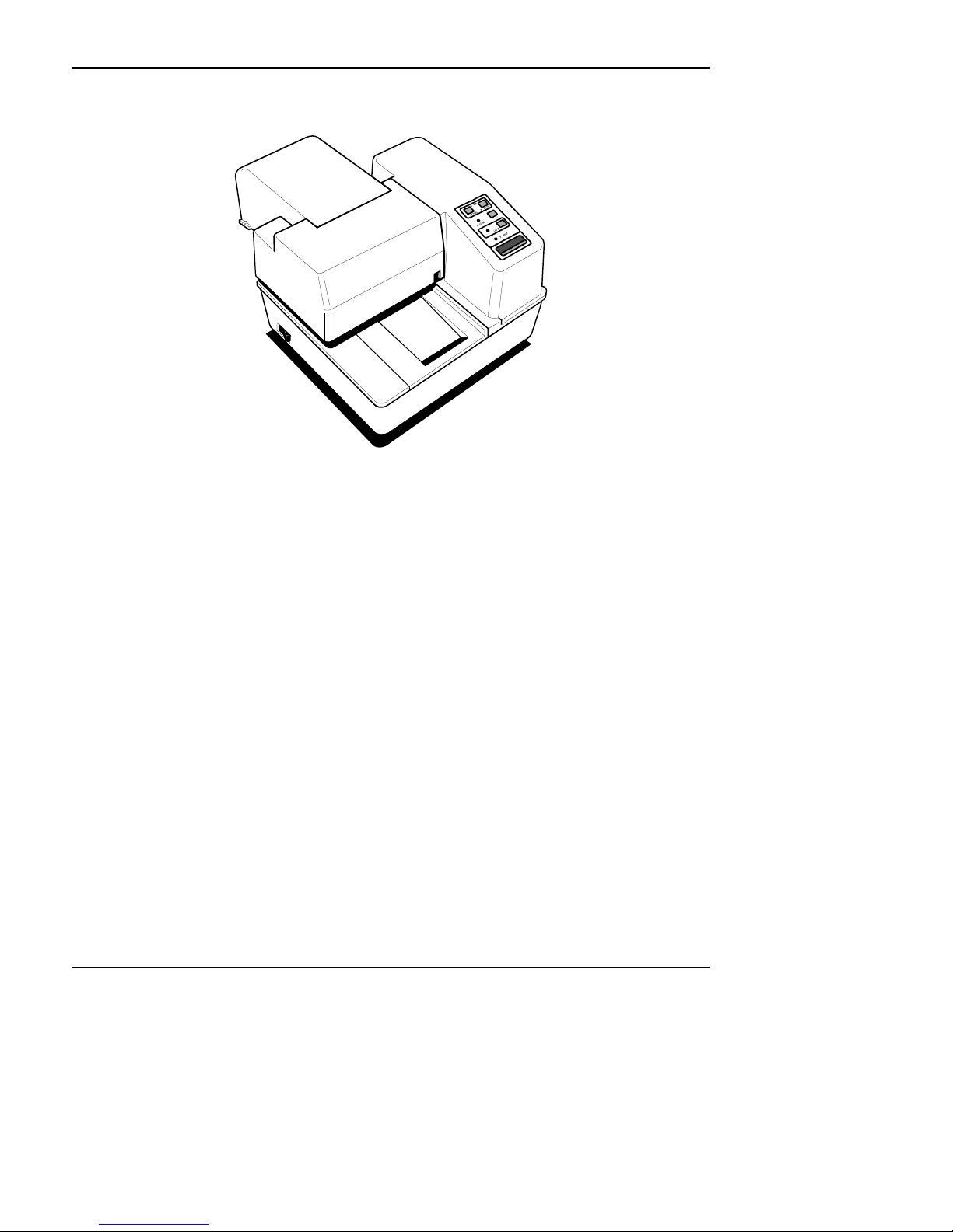
The Ithaca PcOS (personal computer, point-of-sale) Series 60 Printer can be ordered in several configurations to perform a
variety of functions in any point-of-sale operation. The standard model (Model 63) is equipped with all three print stations:
slip, receipt, and journal.
Other models come as either slip, slip and receipt, or slip and journal.
The slip station prints (or validates) on receipts, credit slips, and multi-part forms. The receipt station prints on standard
receipt paper to provide your customers with a record of their purchases. The journal station prints a permanent record of all
your business transactions on standard journal paper.
The unique modular design of the Series 60 Printer allows it to be upgraded or downgraded to perform the same functions
as any other model in the series.
Series 60 Models
There are four models in the Series 60 line of printers, all with the slip station and their own unique set of features. Models
62, 63, and 64 are multi-station printers.
• Ithaca PcOS Model 61 Slip Printer
• Ithaca PcOS Model 62 Slip and Receipt Printer
• Ithaca PcOS Model 63 Slip, Receipt, and Journal Printer
• Ithaca PcOS Model 64 Slip and Journal Printer
PcOS Model 61 Slip Printer
• Prints (or validates) on a variety of forms, such as receipts, credit slips, and multi-part forms (up to four
forms in a multi-part form)
• Prints up to 60 characters at 17 characters per inch
• Prints up to 80 characters at 24 characters per inch on single- or multi-part forms
• Prints rotated characters in 90 degree increments
• Senses the top and bottom of forms
• Ejects forms from either the front or rear of the printer
Rev C 7/8/2008 Page ix
Page 11

Control Codes PcOS Series 60 Programmer's Guide
Paper Motion Ithaca Peripherals Incorporated
PcOS Model 62 Slip and Receipt Printer
• Adds receipt station to Model 61 Slip Printer
• Prints receipts at 10, 12, 17, or 24 characters per inch
• Prints receipts up to 48 columns at 17 characters per inch
• Cuts receipt automatically
• Prints rotated characters in 90 degree increments
PcOS Model 63 Slip, Receipt, and Journal Printer
• Adds receipt and journal stations to Model 61 Slip Printer
• Prints receipts at 10, 12, 17, or 24 characters per inch
• Prints receipts up to 48 columns at 17 characters per inch
• Cuts receipts automatically
• Prints journal up to 40 columns at 17 characters per inch
• Prints rotated characters in 90 degree increments
• Includes standard automatic journal take-up
PcOS Model 64 Slip and Journal Printer
• Adds journal function to Model 61 Slip Printer
• Prints journal up to 40 columns at 17 characters per inch
• Prints rotated characters in 90 degree increments
• Includes standard automatic journal take-up
Standard Features
• Interfaces
• Centronics Parallel Interface, 2K buffer
• RS-232 Serial Interface, 19.2K Baud, 2K buffer
• Up to 7 lines printed per second
• Dual cash drawer drivers with drawer OPEN/CLOSED status
• Snap-on ribbon cassette
• All points addressable graphics
• IBM/Epson compatible
• Self test
• IBM character sets I and II
Optional Features
• Custom PROMS to allow operation in various computer or simulation environments
• Most common languages (number of resident languages depends on language mix
Reliability
• Mean time between failure: 25,000 hours (except printhead)
• Printhead life: 200 million characters
• Auto cutter life: 1 million cuts
• Auto cutter mean time between failure: 300,000 cuts
• Mean time to repair: 15 minutes
Page x Rev C 7/8/2008
Page 12
Programmer's Guide PcOS Series 60 Control Codes
Ithaca Peripherals Incorporated Paper Motion
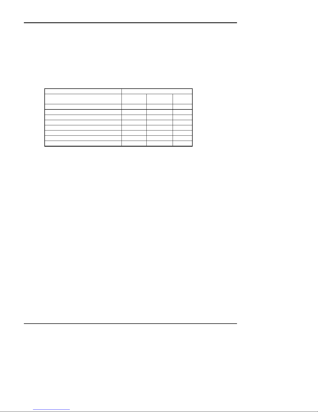
Print Characteristics
Character Information
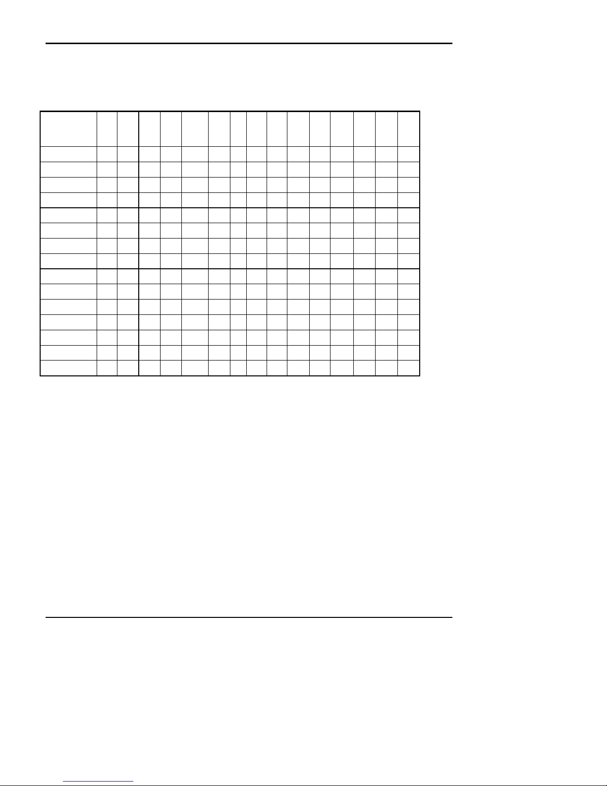
The Ithaca PcOS Series 60 Printers prints characters in a variety of pitches as shown in the following table and print
samples. Each pitch can also be printed in a variety of styles affecting the appearance of the characters and the speed of the
printer.
For information about programming the printer to print a particular pitch or style, please refer to the "Programming" section
on page 29.
Pitch (Characters per inch) Slip
Print Pitch Capability
10 CPI 34 28 24
12 CPI 42 32 28
17 (Condensed) 60 48 40
24 (Super Condensed) 84 66 56
5 (Double Wide) 17 14 12
6 (Double Wide) 21 16 14
8.5 (Condensed Double Wide) 30 24 20
12 (Super Condensed Double Wide) 42 33 28
Note: 10 Characters per inch is sometimes referred to a Pica, 12 CPI is sometimes referred to as
Elite
Rotated Print: The printer can be programmed to rotate characters in 90 degree increments. All rotated print is in the 12
CPI format. For information about programming the printer to rotate characters, please refer to the "Control Codes and
Features sections"
Maximum Characters per Line
Station
Receipt
Station
Journal
Station
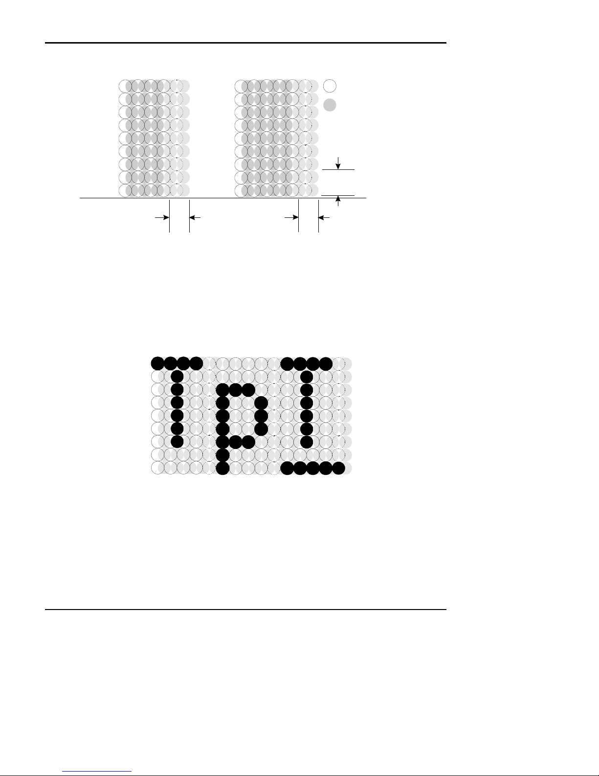
Character Generation
All the character sets and modes are based on one of two character cells, 10 wide by 9 high or 12 wide by 9 high. Double
wide mode, is twice the width of the normal mode or 20 wide by 9 high or 24 wide by 9 high.
In utility print mode he character cell consists of five full dots and five half dots horizontally by nine full dots vertically,
the character is a 9 by 9 character I High Speed Draft mode the character cell is shortened by one half and one full dot
column. This yields a 7 by 9 character.
Each character is justified to the left of the cell. The first four columns of the full dots and the first three columns of half
dots are used to generate the character in high speed draft, while the first five columns of the full dots and the first four
columns of the half dots are used in utility mode. The last full dot and the last two half dots are used for character spacing
in both modes.
Rev C 7/8/2008 Page xi
Page 13
Control Codes PcOS Series 60 Programmer's Guide
Paper Motion Ithaca Peripherals Incorporated
The following illustration shows a single wide character cell:
1 3 5 7 9
2 4 6 8 10
1
2
3
4
5
6
7
8
9
1 3 5 7 9 11
2 4 6 8 10 12
1
2
3
4
5
6
7
8
9
Full Dots
Half Dots
Descender (Row 8 & 9)
& Underline (Row 9)
Character
Spacing
High Speed Draft
Single Wide Character
The example above shows the full dots as adjacent to each other in the character cell. This is true for the 12 CPI mode
only. The 10 CPI mode allows a gap between adjacent full rows, 17 and 24 CPI allow an overlap of full rows.
The printer can not print adjacent full and half dots in any single row. Some graphics (Double Density Half Speed) allow
adjacent rows to be printed by slowing the print speed by half. This allows time between half and full columns to be the
same as between full columns in full speed operation.
The following illustration shows the use of full and half dots as well as descenders to form characters:
1 3 5 7 9
2 4 6 8 10
1
2
3
4
5
6
7
8
9
Character
Spacing
Utility Mode
1 3 5 7 9
2 4 6 8 10
1 3 5 7 9
2 4 6 8 10
Page xii Rev C 7/8/2008
Page 14

Programmer's Guide PcOS Series 60 Control Codes
Ithaca Peripherals Incorporated Paper Motion
Control Codes Overview
This programmer's guide is designed to help users of Ithaca Peripherals Series 60 Slip Printer develop applications. The
Series 60 printers are specialized Point Of Sale POS printers that have several features not normally found on general
purpose printers. Because of these special features, the Series 60 printers have some specialized codes that control these
features. This programmer's guide documents all the control codes with emphases on those codes that are unique to the
Series 60 printer.
All Ithaca Peripherals Series 60 printers have both a serial and parallel interface. Both interfaces provide the same printer
control2 and use the same codes.
Nomenclature
Whenever describing control codes there is confusion as to whether the description is decimal, hex, or ASCII. To minimize
this problem, this users guide will use the following nomenclature when describing control code sequences:
[ ] Enclose a control character. This is a single 8 bit value as defined in the standard ASCII tables. The
< > Enclose an 8 bit value in decimal format. This value will be from 0 to 255
An example would be <2> which would represent 02H or 2 decimal
<n> This indicates a variable parameter. In this case a variable parameter "n" that can have a value of from 0
<n>1 <n>2 This indicates that there are 2 parameters, n1 and n2 where both can have values from 0 to 255.
x All other characters in control strings represent ASCII characters.
For example " [ESC] 1 " Would represent 1BH followed by 31H.
ASCII chart in Appendix A lists all the control codes. An example would be [ESC] which would
represent a 1BH or 26 Decimal
to 255. The meaning of "n" is described and defined in the description of the command.
The CFG60 Configuration and demonstration program3 uses the same nomenclature. All print examples shown in this
manual are available for CFG60.
In many cases, applications require that control sequences be specified in Hex or Decimal codes. In most cases all
commands are specified in ASCII, Hex and Decimal. There is an ASCII chart in the Appendix that lists ASCII, Decimal,
and Hex Equivalents.
IPCL Codes
IPCL (Ithaca Printer Control Language) codes are designed to control a printer without using control characters. Not all
commands are supported by IPCL codes. For those commands that are the IPCL code is listed.
Occasionally an IPCL code will interfere with the text that are to be printed, the IPCL translator can be disabled with an
[ESC]y<4> command.
2
The Serial Interface does provide a few additional interface capabilities because of the ability of the serial interface to be
bi-directional.
3
CFG60 is available from Ithaca Peripherals at no cost. This program runs on IBM PC or compatible.
Rev C 7/8/2008 Page xiii
Page 15

Control Codes PcOS Series 60 Programmer's Guide
Paper Motion Ithaca Peripherals Incorporated
Application Development
To aid in application development there two sections in this manual that are designed to help the programmer understand
the series 60 printer.
The first is a how to section that explains ways to use the special features and get the most out of the printer.
The second section is an explanation of how the printer, it's print buffer, the communications link, and the host computer
interact.
Tables and Charts
Throughout this programmer's guide there are charts and tables that list commands and features. In most cases these charts
cross reference the page that describes the command. Commands are grouped by function and can at times be hard to find.
To minimize the time it takes to find commands, there are two code summary charts in the following section, one ordered
by code and one ordered by function.
Printer Control Codes
Print / Paper Motion
Page xiv Rev C 7/8/2008
Page 16
Programmer's Guide PcOS Series 60 Control Codes
Data Sent to printer
Ithaca Peripherals Incorporated Paper Motion
Low Level Paper Motion Control
Function: Carriage Return
ASCII: [CR]
Hexadecimal: 0DH
Decimal: <13>
IPCL: &%CR
Description: Print contents of print buffer (if any) and reset the next character print position to the left margin. A line
Function: Line Feed
ASCII: [LF]
Hexadecimal: 0AH
Decimal: <10>
IPCL: &%LF
Description: Print contents of buffer (if any) and advance paper one line at the current default line spacing. The next
NOTE: The journal feeds only from back to front.
feed is NOT performed. The left margin is defined by the current print station, the print rotation direction
and the left margin command.
character print position is reset to the left margin. The direction moved is defined by the current print
station, the rotated print command, and the paper motion set by the [ESC] r, [ESC] n or [ESC] o
commands.
Special Paper Motion
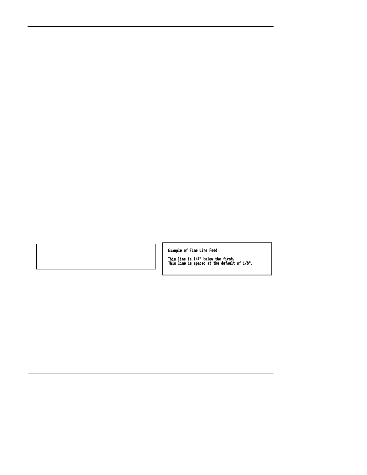
Function: Fine Line Feed
ASCII: [ESC] J <n>
Hexadecimal: 1BH 4AH <n>
Decimal: <27> <74><n>
IPCL: (None)
Description: Print contents of buffer (if any) perform line feed of n/216" . This command does not change the default
NOTE: The journal feeds only from back to front.
line spacing value. The next character print position is reset to the left margin.
Example of Fine Line Feed[CR]
[ESC]J<54>
This line is 1/4" below the first.[CR][LF]
This line is spaced at the default of
1/8".[CR][LF]
Resulting Print
Rev C 7/8/2008 Page xv
Page 17

Control Codes PcOS Series 60 Programmer's Guide
Paper Motion Ithaca Peripherals Incorporated
Function: Feed 2 Inches
ASCII: [ESC] e
Hexadecimal: 1BH 65H
Decimal: <27><101>
IPCL: &%LC
Description: Feed receipt tape 2.0". This command will feed the Receipt out after a cut until there are 3 print lines left.
This command will also work for the slip station in either front to back or back to front direction. It will
Function: Feed 7 Inches
ASCII: [ESC] d
Hexadecimal: 1BH 64H
Decimal: <27><100>
IPCL: &%LC
Description: Feed form 7". This command will feed the Receipt or Slip 7 inches in the last direction selected.
This command does not function in journal mode
Function: Feed to Mark
ASCII: [ESC] k
Hexadecimal: 1BH 6BH
Decimal: <27><107>
IPCL: &%LK
Description: Feed receipt tape 7" or to mark.". This command will feed the Receipt out until a black mark is found on
When the mark is found it will be about 1.75" from the print line. There will be about 14 lines of print (at
NOTE: The knife will not operate if the mark is under the rear slip sensor. The knife safety logic thinks
The Mark must be at least 0.1875" long and 0.75" from the left side of the Receipt. The mark must not
Typically this command is issued to feed the receipt after the receipt is complete.
feed the slip 2.0".
Typically this command is issued to feed the receipt after the receipt is complete, or to eject a form from
the printer
the right side of the receipt tape. Typically this command is issued to feed the receipt to locate a marker
on a pre printed tape.
1/8" spacing ) to the mark.
that the receipt is not loaded and will not cycle. Feed the paper past the mark before cutting. Use an
[ESC] q command before the [ESC] v to force the knife safety logic to wait for the line feeds before
checking the sensors.
reflect IR. light.
Note: This command does not function in journal mode.
Function: Feed to End of Slip
ASCII: [ESC] m
Hexadecimal: 1BH 6DH
Page xvi Rev C 7/8/2008
Page 18
Programmer's Guide PcOS Series 60 Control Codes
Ithaca Peripherals Incorporated Paper Motion
Decimal: <27><109>
IPCL: &%LE
Description: Feed the slip to the edge. This command feeds the slip until either the front or the rear slip sensor no
When the form is fed from front to back the print line will be about 0.375" from the edge. When the form
NOTE: This command does not function in journal mode
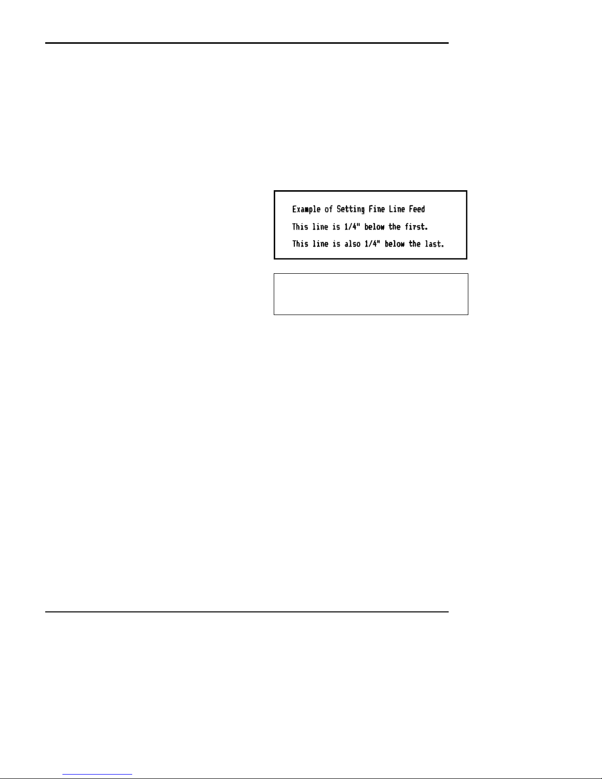
Function: Set Variable Line Space n/216"
ASCII: [ESC] 3 <n>
Hexadecimal: 1BH 33H <n>
Decimal: <27><51><n>
IPCL: &%SV <n>
Description: Set default line spacing to n/216". Set n =1 to
NOTE: This command does not affect journal
Function: Set Line Space 27/216"
ASCII: [ESC] 0
Hexadecimal: 1BH 30H
Decimal: <27><48>
IPCL: &%ST
Description: Set default line spacing to 27/216". This is a standard 8 lines per inch line spacing. This is the default
NOTE: The journal is always printed at 8 lines per inch. This command is accepted and will affect
longer sees the slip. The slip will be fed in the direction last specified. The feed will be a maximum of 7"
and then stop. The ENQ <5> and <6> commands can be used to verify the operation of this command.
A second [ESC] m command can be issued to feed more than 7". If the second command is issued after
the end is found it will not cause any paper motion.
is fed from back to front the print line will be about 1.75" from the edge.
255. This command sets the line feed spacing
used by [LF] to values other than 1/8 or 7/72
inch. This command takes effect immediately as
opposed to the set variable line spacing.
Resulted in this print
spacing. The journal is always 8 lines per inch.
This command is accepted and will affect receipt
and slip mode.
[ESC]3<54>
Example of Setting Fine Line Feed[CR][LF]
This line is 1/4" below the first.[CR][LF]
This l ine is also 1/4" below the
last.[CR][LF]
Data Sent to the printer
text line spacing at power up.
receipt and slip mode.
Rev C 7/8/2008 Page xvii
Page 19
Control Codes PcOS Series 60 Programmer's Guide
Paper Motion Ithaca Peripherals Incorporated
Function: Set Line Space 21/216" or (7/72")
ASCII: [ESC] 1
Hexadecimal: 1BH 31H
Decimal: <27><49>
IPCL: &%SG
Description: Set default line spacing to 21/216". This line spacing is for APA (All Points Addressable) Graphics
NOTE: This command will not affect the journal station. This command is accepted in journal mode and
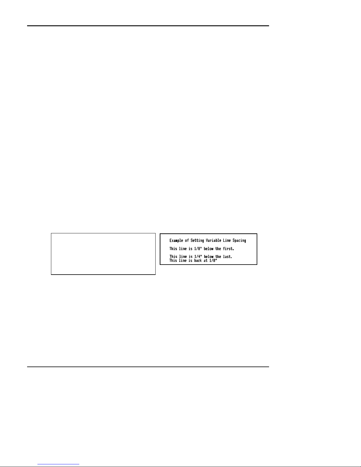
Function: Set Variable Line Space n/72"
ASCII: [ESC] A <n>
Hexadecimal: 1BH 41H <n>1
Decimal: <27><65><n>
IPCL: (None)
Description: Set default line spacing to n1/72. Set n1 =1 to 85. This line spacing does not take effect until enabled by
NOTE: This command will not affect the journal station. This command is accepted and will affect
Function: Enable [ESC] A <n> line spacing.
ASCII: [ESC] 2
Hexadecimal: 1BH 32H
Decimal: <27><50>
IPCL: (None)
Description: Enable [ESC] A <n> line spacing. This is a companion to the [ESC] A <n> command and puts to
NOTE: This command will not affect the journal station. This command is accepted and will affect
printing.
will affect receipt and slip mode when selected.
1
the [ESC] 2 command. This command is provided to maintain backward compatibility with Series 50 and
OKIDATA IBM compatible printers. It can be used to print on pre-printed forms.
receipt and slip mode.
specified line spacing into effect. It will remain in effect until another line spacing command is issued.
receipt and slip mode.
[ESC]A<18>
Example of Setting Variable Line
Spacing[CR][LF]
This line is 1/8" below the first.[CR]
[ESC]2[LF]
This line is 1/4" below the last.[CR]
[ESC]0[LF]
This line is back at 1/8"[CR][LF]
Data Sent to printer
Page xviii Rev C 7/8/2008
Resulting Print
Page 20

Programmer's Guide PcOS Series 60 Control Codes
Ithaca Peripherals Incorporated Paper Motion
Function: Set Line Feed Direction Back to Front
ASCII: [ESC] n
Hexadecimal: 1BH 6EH
Decimal: <27><110>
IPCL: &%LR
Description: Set slip spacing direction from the back to the front of printer. This command sets the feed direction and
NOTE: This command is overridden by a station select command. Selecting the slip station defines the
NOTE: This command will not affect the journal station. This command is excepted and will affect
NOTE: Whenever the slip is moved in the opposite direction of the intended print direction, the feed in
Function: Set Line Feed Direction Front to Back
ASCII: [ESC] o
Hexadecimal: 1BH 6FH
Decimal: <27><111>
IPCL: &%LB
Description: Set slip spacing direction from front to back of printer. This command sets the feed direction and will
NOTE: This command is overridden by a station select command. Selecting the slip station defines the
NOTE: Although this command will work on the receipt station, no more than 1/8 inch should be fed,
NOTE: This command will not affect the journal station. This command is excepted and will affect
NOTE: Whenever the slip is moved in the opposite direction of the intended print, the feed in the non-
will operate in Slip and Receipt mode. This and its companion command [ESC] o can be used to move a
slip into any print position.
feed direction to be from front to back. Selecting the receipt station defines feed direction to be from
back to front. Once the station is selected the [ESC] n command can be used to change the direction.
receipt and slip mode.
the non-print direction should be moved one unit too far. The form should then be repositioned in the
intended print direction. This will minimize positioning errors caused by any mechanical backlash.
operate in Slip and Receipt mode. This and its companion command [ESC] n can be used to move a slip
into any print position.
feed direction to be from front to back. Selecting the Receipt station defines feed direction to be from
back to front. Once the station is selected the [ESC] o command can be used to change the direction.
in the front to back direction. It is possible to cut the receipt, feed the receipt to cut with the [ESC] e
command, and then reverse feed. this will in effect make a slip out of a receipt.
receipt and slip mode.
print direction should be moved one unit too far. The form should then be repositioned in the intended
print direction. This will minimize positioning errors caused by mechanical backlash.
Rev C 7/8/2008 Page xix
Page 21
Control Codes PcOS Series 60 Programmer's Guide
Horizontal Motion Ithaca Peripherals Incorporated
Horizontal Motion Control
There are two commands that can control the horizontal position of characters. Many applications use space control to
positions fields, however, there is the ability to control character position with horizontal tab stops and using the horizontal
tab [HT] to move to those tab stops.
Function: Horizontal Tab
ASCII: [HT]
Hexadecimal: 9H
Decimal: <9>
IPCL: NONE
Description: Inserts spaces in the print buffer up to the next tab stop. The default tab locations are every 8 spaces.
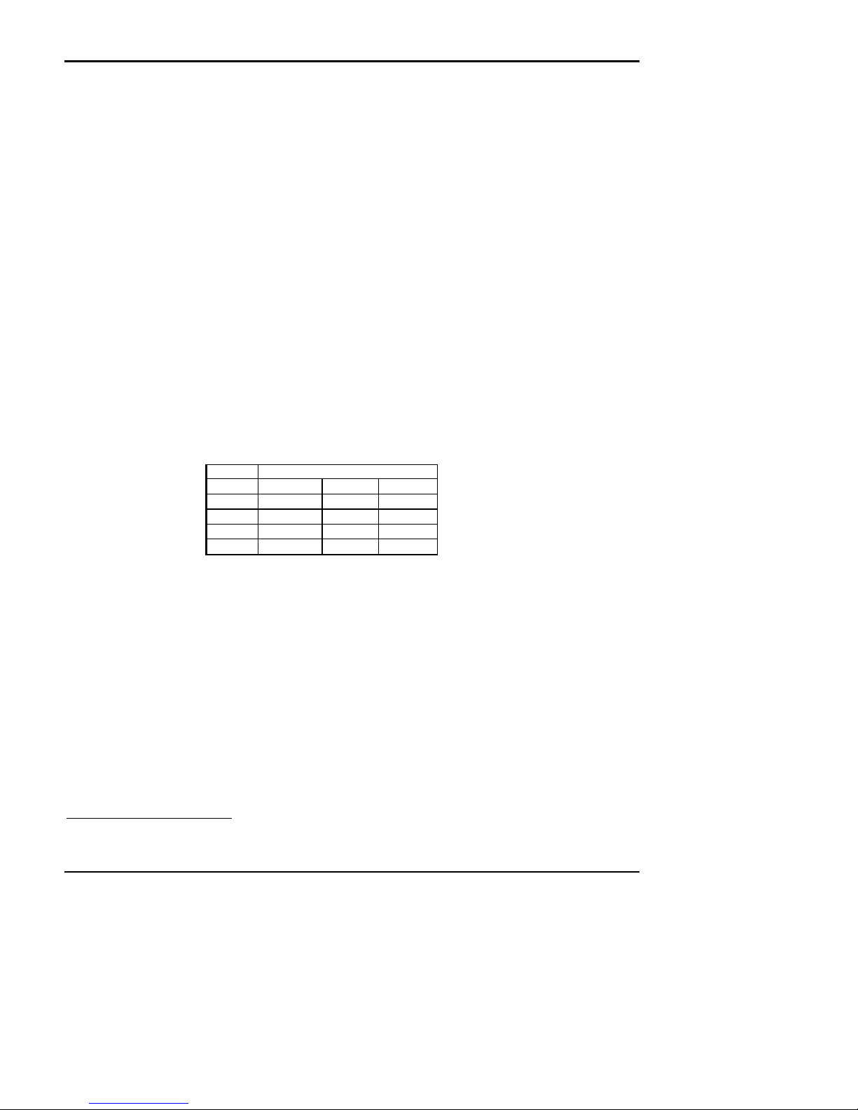
Function: Set Horizontal Tab Stops
ASCII: [ESC] D <n>1 <n>2 <n>3 ... <n>i 0
Hexadecimal: 1BH 75H <n>1 <n>2 <n>3 ... <n>i 00H
Decimal: <27><117><n>1 <n>2 <n>3 ... <n>i <0>
IPCL: NONE
Description: Set tab stops at the character columns specified by <n>. The end of the settings is specified by a <0>.
Column sizes are in accordance with the current character pitch.
Setting tabs that are beyond the station width is possible. A [CR] will be inserted if the tab is used.
The power up default is every 8 spaces, i.e. 9, 17, 25 and so on.
All previously set tabs will be cleared by this command. There is no restore defaults procedure other than
to re specify the tabs.
Printing will begin at the home position.
Pitch Print Station
CPI4
24
17.1
12
10
Slip Receipt Journal
1≤n≤84 1≤n≤66 1≤n≤56
1≤n≤60 1≤n≤48 1≤n≤40
1≤n≤42 1≤n≤32 1≤n≤28
1≤n≤34 1≤n≤28 1≤n≤24
Valid tab stops
4
CPI - Characters Per Inch
Page 20 Rev C 7/8/2008
Page 22
Programmer's Guide PcOS Series 60 Control Codes
Ithaca Peripherals Incorporated Character Pitch
Character Pitch
There are a number of Character pitch and print mode operations that are possible and a few that are not. The following
table lists the operations that are possible in matrix form.
Operation 10
10 cpi
12 cpi
17 cpi
24 cpi
Line Graphics
Super / Sub
Util
NLQ
HSD
Emphasize
Enhanced
Double wide
Underline
Rotate 180°
Rotate 90°/270°
NOTE: Feature Available
Feature NOT Available
Switches to 10 CPI Emphasize. If 17 or 24 CPI was set previously to the emphasize command, the
Prints half high full width utility script.
In rotated 90° or 270° mode the print is done in APA Graphics. The print is in 12 CPI character cell size.
12 cpi 17 cpi 24 cpi Line
cpi
Graphic
s
Super
Util NLQ HSD Emph
/ Sub
asize
Enha
nced
Double
wide
Under
line
Rotate
180
Rotate
90°
/270°
characters will be printed at 10 CPI with Emphasize. When Emphasize is terminated, the print will revert
to 17 or 24 CPI.
The inter-character spacing can be adjusted with the normal line spacing commands.
Rev C 7/8/2008 Page 21
Page 23

Control Codes PcOS Series 60 Programmer's Guide
Character Pitch Ithaca Peripherals Incorporated
Function: Begin 10 CPI character pitch
ASCII: [DC2]
Hexadecimal: 12H
Decimal: <18>
IPCL: &%F3
Description: Set 10 character per inch print pitch.
Function: Begin 12 CPI character pitch
ASCII: [ESC] :
Hexadecimal: 1BH 3AH
Decimal: <27><58>
IPCL: &%F2
Description: Set 12 character per inch print pitch
Function: Begin 17 CPI character pitch
Mode: Global
ASCII: [SI]
Hexadecimal: 0FH
Decimal: <15>
IPCL: &%F1
Description: Set 17 character per inch print pitch
Function: Begin 24 CPI character pitch
Mode: Global
ASCII: [ESC] [SI]
Hexadecimal: 1BH 0FH
Decimal: <27><15>
IPCL: &%F4
Description: Set 24 character per inch print pitch
[DC2]
This line is 10 CPI[CR][LF]
[ESC]:
This line is 12 CPI[CR][LF]
[SI]
This line is 17 CPI[CR][LF]
[ESC][SI]
This line is 24 CPI[CR][LF]
Data sent to the printer
Page 22 Rev C 7/8/2008
Resulting print
Page 24
Programmer's Guide PcOS Series 60 Control Codes
Ithaca Peripherals Incorporated Character Pitch
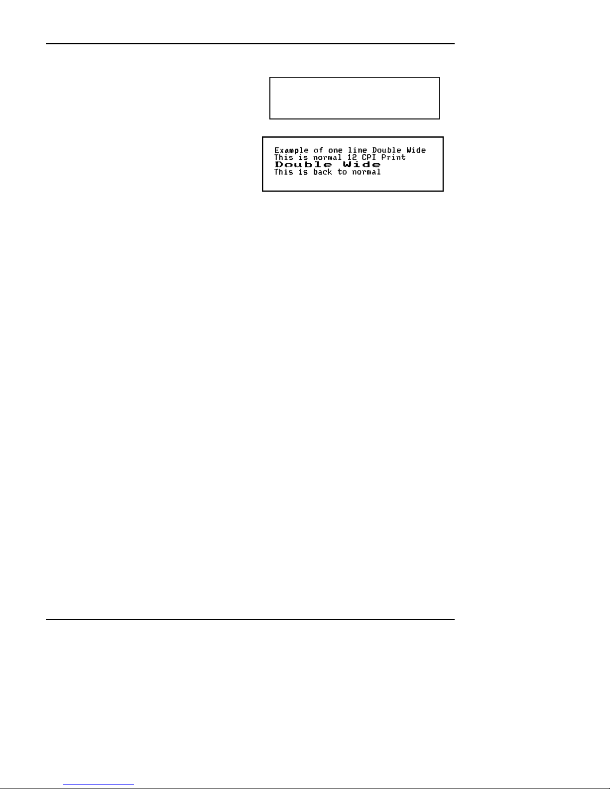
Function: Begin one line double wide print
ASCII: [SO]
Hexadecimal: 0EH
Decimal: <14>
IPCL: &%MW
Description: This command causes subsequent characters to
be printed at twice the currently selected
character width. For example 10 cpi becomes 5
cpi, 17 cpi becomes 8.5 cpi etc. This
command remains in effect until :
a. - a valid line terminator is received ( CR,
LF, or Fine Line Feed)
b. - The command is canceled
c. - The maximum number of characters per
line is reached and the printer performs an auto print
Function: Cancel one line double wide print
ASCII: [DC4]
Hexadecimal: 14H
Decimal: <20>
IPCL: &%MN
Description: Cancel one line double wide mode set by [SO] command. This command allows single and double wide
characters to be printer on the same line.
Function: Begin Multi line double wide print
ASCII: [ESC] W <1>
Hexadecimal: 1BH 57H 01H
Decimal: <27><87><1>
IPCL: &%FD
Description: Begin Multi-line line double wide mode. This command is similar to the [SO] command except that the
printer will remain in double wide mode until the Cancel Multi Line double wide command is received.
Function: Cancel Multi-line line double wide print
ASCII: [ESC] W <0>
Hexadecimal: 1BH 57H 00H
Decimal: <27><87><0>
IPCL: &%FE
Description: Cancel Multi-line line double wide mode set by [ESC] W <1> command
Example of one line Double Wide[CR][LF]
This is normal 12 CPI Print[CR][LF]
[SO]
Double Wide[CR][LF]
This is back to normal[CR][LF]
Data Sent To Printer
Resulting Print
Rev C 7/8/2008 Page 23
Page 25
Control Codes PcOS Series 60 Programmer's Guide
Character Font Ithaca Peripherals Incorporated
Character Font
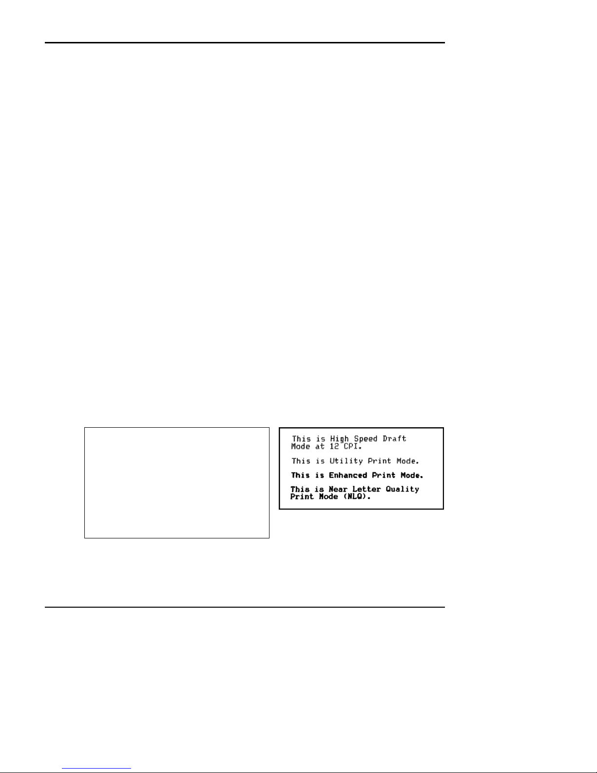
Function: Begin High Speed Draft Mode (HSD) (Power on Default)
ASCII: [ESC] # <0>
Hexadecimal: 1BH 23H 00H
Decimal: <27><35><0>
IPCL: &%QT
Description: Begin Draft print mode (1 pass 7x7 font). Enhanced, Emphasized, Subscript, Superscript, and
To maintain optimum print speed the printer should be returned to High Speed Draft mode when
Function: Begin Utility Print
ASCII: [ESC] I <1>
Hexadecimal: 1BH 49H 01H
Decimal: <27><73><1>
IPCL: &%QU
Description: Begin Utility print mode (1 pass 9x7 font). Utility print mode enables Enhanced, Emphasized,
Function: Begin Enhanced Print
ASCII: [ESC] I <2>
Hexadecimal: 1BH 49H 02H
Decimal: <27><73><2>
IPCL: &%QE
Description: Begin Enhanced print mode (2 pass 9x7 font). Print speed is reduced approximately 40% over the High
Function: Begin NLQ Print
ASCII: [ESC] I <3>
Hexadecimal: 1BH 49H 03H
Decimal: <27><73><3>
IPCL: (None)
Description: Begin NLQ print mode ( 2 pass 9x7 font). This is generally regarded as a Near Letter Quality print node.
Underline character attributes are not available in this mode.
enhanced print is not required.
Subscript, Superscript, and Underline character attributes. Print speed is reduced approximately 20%
over the High speed Mode (HSD).
speed Mode (HSD). The effect is to darken the resulting print
The print speed is reduced and character features are added to the font to enhance the appearance.
[ESC]f[ESC]:
{rpt:5}[LF]
[ESC]v
[ESC]#<0>
This is High Speed Draft [CR][LF]
Mode at 12 CPI.[CR][LF][LF]
[ESC]I<1>
This is Utility Print Mode.[CR][LF][LF]
[ESC]I<2>
This is Enhanced Print Mode.[CR][LF][LF]
[ESC]I<3>
This is Near Letter Quality[CR][LF]
Print Mode (NLQ).[CR][LF][LF]
[ESC]z
Data sent to the printer
Page 24 Rev C 7/8/2008
Resulting Print
Page 26
Programmer's Guide PcOS Series 60 Control Codes
Ithaca Peripherals Incorporated Character Font
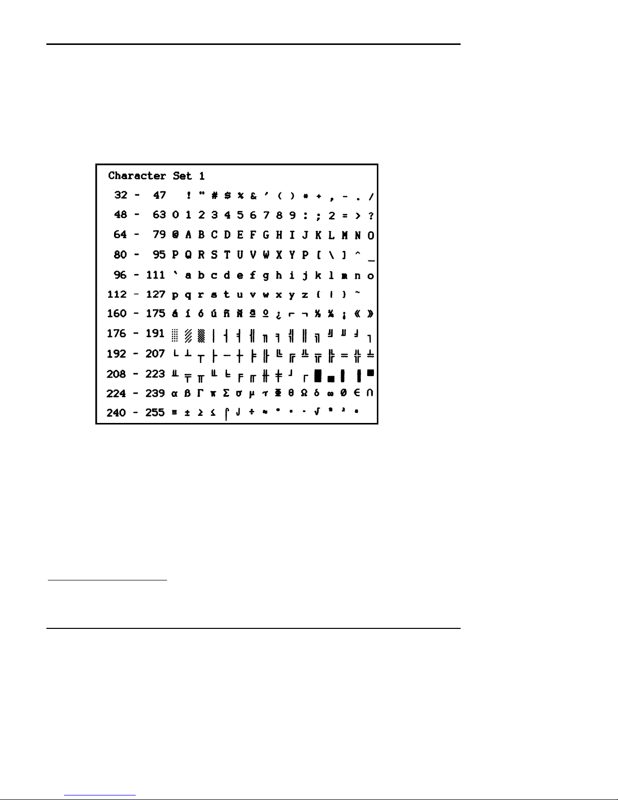
Function: Select Character Set 1 (Default Character set)
ASCII: [ESC] 7
Hexadecimal: 1BH 37H
Decimal: <27><55>
IPCL: &%C1
Description: Select character set 1. This character set consists of characters 32 through 127 and 160 through 255 in
the character chart below. Characters 128 through 1595 are not implemented and should not be sent to
the printer.
NOTE: Characters 176 through 228 (Block Graphics) and 244 should not be used in journal mode as they
are multiple pass fonts that will not print well on the journal.
5
Because of limited code space the validity of characters between 128 and 159 are not checked in character set 1. In most
cases sending these values to the printer will have unexpected effects.
Rev C 7/8/2008 Page 25
Page 27
Control Codes PcOS Series 60 Programmer's Guide
Character Font Ithaca Peripherals Incorporated
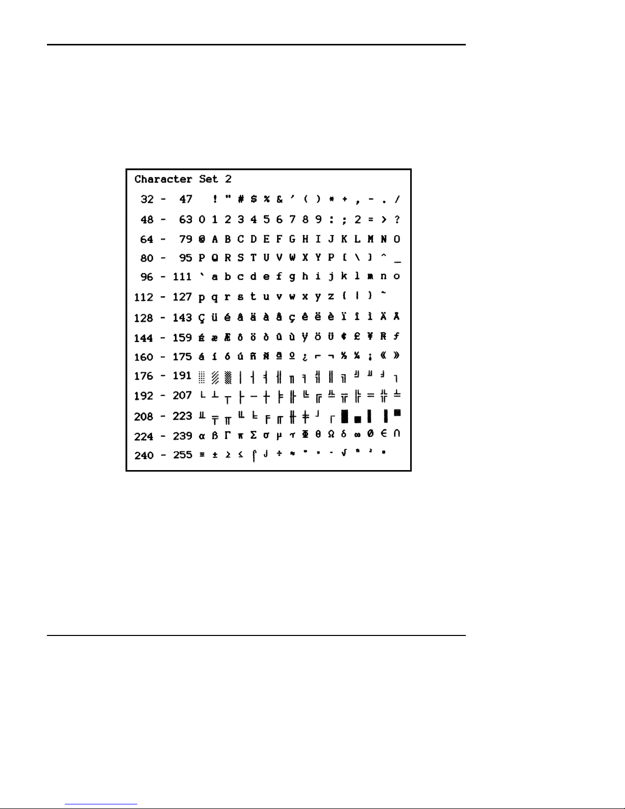
Function: Select Character Set 2
ASCII: [ESC] 6
Hexadecimal: 1BH 36H
Decimal: <27><54>
IPCL: &%C2
Description: Select character set 2. This is a full character set. It includes characters between 32 and 255 from the
NOTE: Characters 176 through 228 (Block Graphics) and 244 should not be used in journal mode as they
chart below.
are multiple pass fonts that will not print well on the journal.
Page 26 Rev C 7/8/2008
Page 28
Programmer's Guide PcOS Series 60 Control Codes
Ithaca Peripherals Incorporated Print Rotation
Print Rotation Commands
To provide flexibility in printing on preprinted and various size forms, rotated print capability is provided in slip and receipt
mode. This mode will rotate the print in any of three 90 degree orientations.
In 90° and 270° rotated mode, the print data is first buffered by the printer, processed (rotated) and then printed. This
causes the print process to be delayed slightly as it takes some time to process the data before it is printed. In 180° mode,
the print is simply inverted.
Because the rotated 90° and 270° print buffer is limited to 1024 characters, the amount of rotated print is limited. The
technique used by the Series 60 printer is to receive all the print to be rotated and convert it into graphics. This requires
buffer space for all possible characters in each print line. Each line has a fixed length buffer regardless of how much data is
actually sent to the printer. The printer will space fill the buffer for each line to the maximum size. This means that a short
line of two characters will take as much buffer space as a long line.
To make the most efficient use of buffer space the line length is pre defined. The default line length is 48 characters which
leaves room for 21 lines. To allow longer lines to be printed the line length can be changed, however no more than 25 lines
are allowed and no more than 80 characters per line are allowed. For example if the line length is expanded to 80 there is
buffer space for 1024/80 or 12 lines.
The spacing between lines is controlled by a line spacing table. This table is defined by the rotated print line spacing
([ESC] u ... ) command. This command specifies the number of dots between each printed line. Each line has an entry in
the table. There is room for 25 lines in the table. The default and minimum is one dot or 1/60 of an inch between lines or 6
2/3 lines per inch.
The character cell is a 5x8 with one dot of white space min. If the spacing between lines is set to 1 the character cell will be
5x9. If the spacing is set to 2 dots the cell will be 5 x 10 and so on. The following table specifies lines per inch for various
numbers of inserted dots.
Number of dots added 1 2 3 4 5 6 7
Cell Size 5x9 5x10 5x11 5x12 5x13 5x14 5x15
Line spacing (inches) 0.15" 0.167 0.183 0.20 0.22 0.23 0.25
Number Lines/inch 6.667 6 5.45 5 4.62 4.29 4
In rotated 90° or 270° mode the print is done in APA6 Graphics. The print is in a modified 12 CPI character cell size. The
inter-character spacing is adjusted with the normal line spacing commands. The [ESC]3<n> command is the most
effective command for adjusting inter character spacing. Because the character is close to a 12 CPI cell, much less than 12
CPI will force the characters to overlap. (Spacing of 12 CPI is obtained with an [ESC] 3 <18>.)
When rotate 90° or 270° is selected only normal text can be printed. Underline, Enhanced, Emphasized and other attributes
will not function. See chart on page 21 for a list of available features.
In rotated 180° mode the 10, 12, 17, and 24 CPI spacing commands are effective. This mode of operation simply inverts
and mirrors the print operation. All line spacing and print features are available. It should be noted that the feed direction
is not affected by any of the rotate commands.
6
APA - All Points Addressable
Rev C 7/8/2008 Page 27
Page 29

Control Codes PcOS Series 60 Programmer's Guide
Print Rotation Ithaca Peripherals Incorporated
Function: Begin 90 Degree Rotated Print
ASCII: [ESC] r <1>
Hexadecimal: 1BH 72H 01H
Decimal: <27><114><1>
IPCL: &%R1
Description: Print data is entered in normal left to right, top to bottom format. When an End Rotated Print ([ESC] r
NOTE: Do not use this command in journal mode. It will not function correctly.
Function: Begin 270 Degree Rotated Print
ASCII: [ESC] r <3>
Hexadecimal: 1BH 72H 03H
Decimal: <27><114><3>
IPCL: &%R3
Description: Print data is entered in normal left to right, top to bottom format. When an End Rotated Print ([ESC] r
NOTE: In receipt mode this rotation requires that the text be sent to the printer in reverse. The feed
NOTE: Do not use this command in journal mode. It will not function correctly.
Function: Begin 180 Degree Rotated Print
ASCII: [ESC] r <2>
Hexadecimal: 1BH 72H 02H
Decimal: <27><114><2>
IPCL: &%R2
Description: All subsequent lines will be rotated 180 degrees and positioned at the opposite margin. This command is
NOTE: The last line of print must be terminated with a line terminator before the END rotated command
NOTE: The definition of normal is rotated 180° on the slip station.
<0>) command is received, the printer will format and print the data. The print will be rotated 90
degrees according to the current stored format parameters. In slip mode, the rotated pattern will be 180
degrees different than in receipt mode. However, the resulting print will be the same provided the feed
direction is correct.
<0>) command is received, the printer will format and print the data. The print will be rotated 270
degrees according to the current stored format parameters.
direction in receipt mode must always be from back to front. It is recommended that only rotate 90° be
used on the receipt.
effective on all stations including the journal. This command will remain in effect until rotation is
canceled with an End Rotated Print ([ESC] r <0>) command, or a station select command is issued.
is issued. Any characters in the print buffer that have not been printed will not be printed. They will be
printed un-rotated when a line terminator is received.
Page 28 Rev C 7/8/2008
Page 30
Programmer's Guide PcOS Series 60 Control Codes
Ithaca Peripherals Incorporated Print Rotation
Function: End Rotated Print
ASCII: [ESC] r <0>
Hexadecimal: 1BH 72H 00H
Decimal: <27><114><0>
IPCL: &%R0
Description: Print contents of rotated print buffer ( if 90 or 270 degree mode) and return to normal print orientation.
In 180 degree mode the printer will return to normal mode. Characters in the print buffer that have not
NOTE: The definition of normal is rotated 180 on the slip station.
Function: Set Rotated Print Line Length
ASCII: [ESC] s <n>
Hexadecimal: 1BH 73H <n>
Decimal: <27><115><n>
IPCL: &%RL <n>
Description: Sets the print line length to be used in Auto Format rotated print mode. The maximum number of
The number of available print lines is found by dividing 1024 by the number of characters per line and
Function: Set Rotated Print Line spacing
ASCII: [ESC] u <n>1 <m>1 <n>2 <m>2... <n>i <m>i 0
Hexadecimal: 1BH 75H <n>1 <m>1 <n>2 <m>2 ... <n>i <m>i 00H
Decimal: <27><117><n>
IPCL: &%RP <n>1<m>1 <n>2 <m>2 ... <n>i <m>i 0
Description: Adjust line spacing for each rotated print line. Where ni is the line number, mi is the spacing in dot
For the first print line the distance is calculated from the margin. An ni value of 0 is used to terminate the
The value of m can be from 1 to 127, n can be from 1 to 25.
NOTE: When this command is used ENQ processing must be disabled. This will prevent unwanted ENQ
been printed will NOT be printed.
characters is 80 per line. The power on default line length is 48 characters.
rounding down to the nearest whole number. The minimum number is 40 characters. Any value less
than 40 will not allow any additional print lines to be printed.
1
<m>1 <n>2 <m>2 ... <n>i <m>i <0>
columns (1/60") from the previous line.
command. Any unspecified spacing will be set to 1. This allows data to be accurately positioned on an
inserted form. These values will be used as a template for all subsequent rotated print. On power up, all
spacings are preset to 1/60" (n=1, 6.667 Lines per inch) for all lines. This command is only effective in
90° and 270° degree rotation. It will remain in effect until a new table is received or until the printer is
power cycled. An [ESC] u <0> will have the effect of setting all lines to 1.
responses.
Number of dots added 1 2 3 4 5 6 7
Cell Size 5x9 5x10 5x11 5x12 5x13 5x14 5x15
Line spacing (inches) 0.15" 0.167 0.183 0.20 0.22 0.23 0.25
Number Lines/inch 6.667 6 5.45 5 4.62 4.29 4
The following chart illustrates the line spacing command.
Rev C 7/8/2008 Page 29
Page 31

Control Codes PcOS Series 60 Programmer's Guide
Print Rotation Ithaca Peripherals Incorporated
Left Margin
n=1, m
n=2, m
The print example on the right is an example of rotated print. It was obtained with the following print codes:
[ESC]h
[ESC]m[ESC]m[ESC]n[ESC]e[ESC]h
[ESC]1
[ESC]r<1>
Ithaca Peripherals Incorporated [CR][LF]
20 Bomax Drive [CR][LF]
Ithaca, New York, 14850 [CR][LF]
[CR][LF]
{date:0} {time:1}[CR][LF]
Series 60 Slip Printer [CR][LF]
Rotated Print Mode [CR][LF]
[CR][LF]
*************************************[CR][LF]
* INNOVATIVE *[CR][LF]
* SOLUTIONS *[CR][LF]
* FOR *[CR][LF]
* RETAIL *[CR][LF]
* AND *[CR][LF]
* FINANCIAL *[CR][LF]
* APPLICATIONS *[CR][LF]
*************************************[CR][LF]
[ESC]r<0>[ESC]0[ESC]n
{rpt:32}[LF]
[ESC]z
Data Sent to the printer
Edge of form
First line
Second Line
Third Line
Page 30 Rev C 7/8/2008
Resulting Print
Page 32

Programmer's Guide PcOS Series 60 Control Codes
Ithaca Peripherals Incorporated Character Attributes
Character Attribute Commands
Function: Begin Underline
ASCII: [ESC] - <1>
Hexadecimal: 1BH 2DH 01H
Decimal: <27><45><1>
IPCL: &%MU
Description: Begin Underline print mode. All subsequent text and leading spaces will be underlined. Trailing spaces
NOTE: Underline is not available in Enhanced Print Modes. See page 21 for available modes.
Function: End Underline
ASCII: [ESC] - <0>
Hexadecimal: 1BH 2DH 00H
Decimal: <27><45><0>
IPCL: &%CU
Description: Ends Underline print mode.
Function: Begin Enhanced Print
ASCII: [ESC] G
Hexadecimal: 1BH 47H
Decimal: <27><71>
IPCL: &%ME
Description: All subsequent text will be printed in enhanced print mode (2 pass w/ vertical offset). Enhanced printing
NOTE: This mode is not available on the journal.
Function: End Enhanced Print Mode
ASCII: [ESC] H
Hexadecimal: 1BH 48H
Decimal: <27><72>
IPCL: &%CE
Description: Cancel Enhanced print mode and return to currently selected font.
Function: Begin Emphasized Print
ASCII: [ESC] E
Hexadecimal: 1BH 45H
Decimal: <27><69>
IPCL: &%MM
Description: Begin Emphasized print mode (1 pass w/ horizontal offset). This print is bolder than normal print.
Function: End Emphasized Print
ASCII: [ESC] F
Hexadecimal: 1BH 46H
Decimal: <27><70>
IPCL: &%CM
Description: Cancel Emphasized print mode
Function: Select Superscript
ASCII: [ESC] S <0>
Hexadecimal: 1BH 53H 00H
Decimal: <27><83><0>
IPCL: &%SP
are also underlined.
provides a deeper resolution of each character and may enhance multiple part form printing.
Rev C 7/8/2008 Page 31
Page 33

Control Codes PcOS Series 60 Programmer's Guide
Character Attributes Ithaca Peripherals Incorporated
Description: Selects Superscript. All following characters will be printed half size on the upper side of the print line.
NOTE: This feature is not available in all print modes. See page 21 for available modes.
Function: Select Subscript
ASCII: [ESC] S <1>
Hexadecimal: 1BH 53H 01H
Decimal: <27><83><1>
IPCL: &%SB
Description: Selects Subscript. All following characters will be printed half size on the bottom side of the print line.
NOTE: This feature is not available in all print modes. See page 21 for available modes.
Function: End Superscript or Subscript
ASCII: [ESC] T
Hexadecimal: 1BH 53H
Decimal: <27><84>
IPCL: &%SE
Description: Ends Superscript or Subscript.
[ESC]f
[ESC]:
[ESC]I<1>
[ESC]v
{RPT:5}[LF]
This is an example of [ESC]-<1>Underline[ESC]<0>.[CR][LF][LF]
[ESC]G
This is Enhanced Mode[CR][LF][LF]
[ESC]H
[ESC]E
This is Emphasized Mode[CR][LF][LF]
[ESC]F
This is [ESC]S<0>Superscript[ESC]T[CR][LF][LF]
This is [ESC]S<1>Subscript[ESC]T[CR][LF][LF]
[ESC]z
Data Sent to the printer
Resulting Print
Page 32 Rev C 7/8/2008
Page 34

Programmer's Guide PcOS Series 60 Control Codes
Ithaca Peripherals Incorporated Graphics
Graphics Mode
NOTE: Be sure to disable ENQ commands before sending graphics data.
NOTE: The journal feeds only from back to front.
Function: Begin Unidirectional Print
ASCII: [ESC] U <1>
Hexadecimal: 1BH 55H 01H
Decimal: <27><85><1>
IPCL: &%GU
Description: Print all data in unidirectional print mode to improve line to line registration for graphics data.
NOTE: This command should be canceled before normal text is printed. It will slow print if it is not
Function: Begin Bi-directional Print
ASCII: [ESC] U <0>
Hexadecimal: 1BH 55H 00H
Decimal: <27><85><0>
IPCL: &%GB
Description: Print all data in bi-directional, logic seeking print mode.
Function: Print Single Density Graphics ( 60 72dpi)
ASCII: [ESC] K <n>1 <n>2
Hexadecimal: 1BH 4BH <n>
Decimal: <27><75><n>1 <n>2
IPCL: &%GS <n>1 <n>2
Description: Print n1 + 256*n2 bytes of single density graphics (60 dpi).
Function: Print Double Density Graphics ( 120 x 72dpi)
ASCII: [ESC] L <n>1 <n>2
Hexadecimal: 1BH 4CH <n>1 <n>2
Decimal: <27><76><n>1 <n>2
IPCL: &%GD <n>1 <n>
Description: Print n1 + 256*n2 bytes of double density graphics (120 dpi)
Function: Print Double Density Graphics ( 120 x 72 dpi)
ASCII: [ESC] Y <n>1 <n>2
Hexadecimal: 1BH 59H <n>1 <n>2
Decimal: <27><89><n>1 <n>2
IPCL: &%GF <n>1 <n>2
Description: Print n1 + 256*n2 bytes of double density graphics (120 dpi) full speed, no consecutive dots.
canceled.
1
<n>2
2
Rev C 7/8/2008 Page 33
Page 35

Control Codes PcOS Series 60 Programmer's Guide
Station Control Ithaca Peripherals Incorporated
Station Control
The Series 60 printer differs from a normal computer type printer in that it is meant for retail point of sale applications.
This requires that the printer have control sequences that are not normally found in data processing and general purpose
printers. These commands fall into two categories; Station Control and Miscellaneous control.
Function: Load Receipt Paper
ASCII: [ESC] f
Hexadecimal: 1BH 66H
Decimal: <27><102>
IPCL: &%SR
Description: Enter receipt mode. This command reset margins, homes the print head and positions receipt tape under
While the receipt tape in still in the receipt paper path, the feed direction should not be reversed.
Function: Activate Receipt Cutter
ASCII: [ESC] v
Hexadecimal: 1BH 76H
Decimal: <27><118>
IPCL: &%FC
Description:. Cut receipt tape. This command is only active in receipt mode when both sensors are covered. It will cut
Function: Select Journal Station
ASCII: [ESC] g
Hexadecimal: 1BH 67H
Decimal: <27><103>
IPCL: &%SJ
Description: Enter journal mode. Reset margins and home the print head. All subsequent data will be printed on the
Under normal operation, if the journal is selected while there is a slip or receipt in the printer an alarm
If the slip clamp is closed and only the front sensor is covered the printer will accept a "select journal"
To leave the slip clamp closed after a slip or receipt operation, feed the receipt or slip from back to front
print head. The paper feed direction is set from back to front. All subsequent data will be printed on the
receipt.
the receipt tape 3.0" from the current print line. Printing can continue to 0.5" from the end of the receipt.
journal tape.
will be displayed. To optimize the printing of journal entries after slip and receipt operations, there is a
way to issue a journal select command and have the printer wait for the slip or receipt to be removed.
command and wait for the front sensor to be cleared. The printer will then start automatically start the
journal operation.
until it is out from under the feed rollers. Leave the slip clamp closed and start the journal operation.
When the slip or receipt is removed the journal print will start after a short delay.
Page 34 Rev C 7/8/2008
Page 36

Programmer's Guide PcOS Series 60 Control Codes
Note: Model 61 and 62 printers will accept forms less than 4.0".
Ithaca Peripherals Incorporated Station Control
Function: Open Slip Clamp
ASCII: [ESC] z
Hexadecimal: 1BH 7AH
Decimal: <27><122>
IPCL: &%SO
Description: Open Forms Compensation Assembly for insertion/removal of slip. This command can also be used to
Function: Clamp on Slip
ASCII: [ESC] j
Hexadecimal: 1BH 6AH
Decimal: <27><106>
IPCL: &%SN
Description: Enter slip mode. This command resets the margins, homes the print head and clamps on the inserted
If there is no form present or it is not fully inserted the command will NOT generate an error.
If the application program in the host computer is to control the slip insertion before the command is
Function: Load Slip , Position to first print line
ASCII: [ESC] i
Hexadecimal: 1BH 69H
Decimal: <27><105>
IPCL: &%SF
Description: Enter slip mode and position slip to first print line. This
If there is no form present or it is not fully inserted, the command will generate an error. The error can be
If the application program in the host computer is to control the slip insertion, the ENQ 5 and 6 status
release the receipt.
form.
issued the ENQ 5 and 6 status request codes can be sent to the printer to query the sensor status.
command resets the margins, homes the print head and
clamps on the inserted form. It then positions the form
to the first available print line. The first line is 0.75
Form Requirements for [ESC] i and [ESC] h
3.5" Min.
4.0" Min.
4.0" Min
Top View
inches from the top of form7.
cleared by pressing the Select key, inserting the form correctly and reselecting the printer.
request commands can be sent to the printer to query the sensor status before the Load Slip command is
issued.
7
It is possible to print closer than 0.75 inches of the top of the form. Byusing the [ESC] b or [ESC]B commands.
However, you will not be able to print within 0.75 Inches of the bottom of the form.
Rev C 7/8/2008 Page 35
Page 37

Control Codes PcOS Series 60 Programmer's Guide
Note: Model 61 and 62 printers will accept forms less than 4.0".
Station Control Ithaca Peripherals Incorporated
Function: Load Slip , Position to first print line
ASCII: [ESC] M
Hexadecimal: 1BH 4DH
Decimal: <27><77>
IPCL: &%SF
Description: Enter slip mode and position slip to first print line.
This command resets the margins, homes the print
head and clamps on the inserted form. It then
positions the form to the first available print line. The
first line is 0.75 inches from the top of form.
If there is no form present, the command will generate an error. The error can be cleared by pressing the
Select key, inserting the form correctly and reselecting the printer.
Unlike the [ESC] i command this command requires that only the front Slip Sensor be covered and the
form be under the feed rolls. The printer will load the form to the rear sensor to check for alignment. If
the form is not found an error is generated. The form must be at least 2.5 Inches long and 4.0 Inches wide
for proper operation.
If the application program in the host computer is to control the slip insertion, the ENQ 5 status request
command can be sent to the printer to query the sensor status before the Load Slip command is issued.
Function: Load Slip, Position to Top of Form
ASCII: [ESC] h
Hexadecimal: 1BH 68H
Decimal: <27><104>
IPCL: &%SL
Description: Enter slip mode and position the slip to the top of the form. This command resets the margins, homes the
print head and clamps on the inserted form. It then positions the form to the edge of the rear slip sensor.
This is 1.75 inches from the top of form.
If there is no form present or it is not fully inserted the command will generate an error. The error can be
cleared by pressing the Select key, inserting the form correctly, and reselecting the printer.
If the application program in the host computer is to control the slip insertion, the ENQ 5 and 6 status
request commands can be sent to the printer to query the sensor status before the Load Slip command is
issued.
Function: Load Slip, Position to Top of Form
ASCII: [ESC] N
Hexadecimal: 1BH 4EH
Decimal: <27><78>
IPCL: &%SQ
Description: Enter slip mode and position the slip to the top of the form. This command resets the margins, homes the
print head and clamps on the inserted form. It then positions the form to the edge of the rear slip sensor.
This is 1.75 inches from the top of form.
If there is no form present the command will generate an error. The error can be cleared by pressing the
Select key, inserting the form correctly, and reselecting the printer.
Unlike the [ESC] h command this command requires that only the front Slip Sensor be covered. The
printer will load the form to the rear sensor to check for alignment. If the form is not found an error is
generated. The form must be at least 2.5 Inches long and 4.0 Inches wide for proper operation.
If the application program in the host computer is to control the slip insertion, the ENQ 5 status request
command can be sent to the printer to query the sensor status before the Load Slip command is issued.
Function: Load Slip, Position to Top of Form (rotated 180°)
Form Requirements for [ESC] M and [ESC] N
Top View
2.0" Min.
2.5" Min.
4.0" Min
Page 36 Rev C 7/8/2008
Page 38

Programmer's Guide PcOS Series 60 Control Codes
Note: Model 61 and 62 printers will accept forms less than 4.0".
Form Requirements for [ESC] b
Form Requirements for [ESC] B
Ithaca Peripherals Incorporated Station Control
ASCII: [ESC] b
Hexadecimal: 1BH 62H
Decimal: <27><98>
IPCL: &%SW
3.5" Min.
4.0" Min.
Description: Enter slip mode and position the slip to the top of the
form. This command resets the margins, homes the
print head and clamps on the inserted form. It then
positions the form to the first print line of the form 0.35
inches from the top of the form.
4.0" Min
Unlike previous slip load commands, this command
prints upside down and as the form moves out of the printer. That is the top of the form is toward the
operator.
If there is no form present the command will generate an error. The error can be cleared by pressing the
Select key, inserting the form correctly, and reselecting the printer.
Unlike the [ESC] B command this command requires that both the front and the rear Slip Sensor be
covered. If the edge of the form is not found an error is generated. The form must be at least 3.5 Inches
long and 4.0 Inches wide for proper operation.
If the application program in the host computer is to control the slip insertion, the ENQ 5 status request
command can be sent to the printer to query the sensor status before the Load Slip command is issued.
Function: Load Slip, Position to Top of Form (rotated 180°)
ASCII: [ESC] B
Hexadecimal: 1BH 42H
Decimal: <27><66>
IPCL: &%SX
2.0" Min.
2.5" Min.
Description: Enter slip mode and position the slip to the top of the
form. This command resets the margins, homes the
print head and clamps on the inserted form. It then
positions the form to the first print line of the form
0.35 inches from the top of the form.
4.0" Min
Note: Model 61 and 62 printers will accept forms less than 4.0".
Unlike previous slip load commands, this command prints upside down and as the form moves out of the
printer. That is the top of the form is toward the operator.
If there is no form present the command will generate an error. The error can be cleared by pressing the
Select key, inserting the form correctly, and reselecting the printer.
Unlike the [ESC] b command this command requires that only the front Slip Sensor be covered. If the
edge of the form is not found an error is generated. The form must be at least 2.5 Inches long and 4.0
Inches wide for proper operation.
If the application program in the host computer is to control the slip insertion, the ENQ 5 status request
command can be sent to the printer to query the sensor status before the Load Slip command is issued.
Function: Set Slip Left Print Margin
ASCII: [ESC] p <n>
Hexadecimal: 1BH 70H <n>
Decimal: <27><112>
IPCL: &%LM <n>
Description: Set left print margin in 1/60" increments where 0< n < 127. This is the left as you look at the printer
from the front or view the resulting print. If in rotated 180 Degree print mode the left margin is on the
right of the printer but still on the left of the printed form.
NOTE: This command works only in slip mode.
Function: Enable or Disable Dual Station Operation
ASCII: [ESC] l <n>
Top View
Top View
Rev C 7/8/2008 Page 37
Page 39

Control Codes PcOS Series 60 Programmer's Guide
Station Control Ithaca Peripherals Incorporated
Hexadecimal: 1BH 6CH <n>
Decimal: <27><108><n>
IPCL: &%SD (Enable Dual Station)
IPCL: &%SS (Single Station)
Description: If n = 1 Dual Station is enabled. In this mode both the Receipt and Journal (or the Slip and Journal) will
feed. This allows the journal to record the information printed on the receipt or inserted form. If n = 0
the printer will revert back to single station operation. The effect of this command is to enable journal
feed in Slip and Receipt modes.
This mode requires that the journal paper be self-printing and the print to be recorded on the journal be
centered on the journal print zone.
Note: The journal will feed back to front with fixed feed only. This should be taken into consideration
when this mode is used.
When any station select commands are issued, the printer will revert to single station operation.
Page 38 Rev C 7/8/2008
Page 40

Programmer's Guide PcOS Series 60 Control Codes
Ithaca Peripherals Incorporated Station Control
Miscellaneous Control
Function: Clear Print Buffer
ASCII: [CAN]
Hexadecimal: 18H
Decimal: <24>
IPCL: &%RD
Description: Clears print buffer. This command clears any unprinted information in the printer received before the
If the input buffer is not being processed (because the printer is out of paper or the form is not inserted)
If the serial interface is being used an [ENQ] <10> will reset the printer and clear any clearable errors. In
The CAN command does NOT restore default conditions. It only clears the print buffers.
Function: Wait in Print Que.
ASCII: [ESC] q
Hexadecimal: 1BH 71H
Decimal: <27><113>
IPCL: NONE
Description: This command waits at the output of the print buffer Que. until the printer has completed all previous
Function: Wait for Print Que.
ASCII: [ESC] Q
Hexadecimal: 1BH 51H
Decimal: <27><81>
IPCL: NONE
Description: This command waits at the output of the print buffer Que. until the printer has completed all previous
In serial mode this command will return an [ETX] to the host. In parallel mode a busy/acknowledge
[CAN].
the CAN command will not be processed until after the error is cleared.
parallel mode toggling the INIT signal will reset the printer. Both of these "Reset" operations will reset
the printer to the power on defaults.
tasks. This command is used to allow ENQ <3> commands to return buffer not empty until the printer
has completed all operations. This has no effect on print data or print mode.
tasks. This command will respond to the host with an acknowledge when all previous commands have
been completed. This has no effect on print data or print mode.
sequence will be issued. A detailed description of this response is described in the Parallel & Serial Port
Acknowledge sections.
Rev C 7/8/2008 Page 39
Page 41

Control Codes PcOS Series 60 Programmer's Guide
Control Ithaca Peripherals Incorporated
Function: Open Cash Drawer
ASCII: [ESC] x <n>
Hexadecimal: 1BH 78H <n>
Decimal: <27><120><n>
IPCL: &%D1 For Cash Drawer 1
IPCL: &%D2 For Cash Drawer 2
Description: Energize cash drawer n for 150 msec.
Note: The open cash drawer commands are processed as part of print data. They are not processed until
Note: Cash drawer 1 is the connector nearest the communications cable.
Note: Cash drawer 2 is configurable in one of two modes. Either pin 2 or 3 is active depending on an
they are found in the input buffer by the print processor. They are not immediate commands.
internal jumper setting. The factory default is pin 3. Cash drawer 1 is always on pin 2.
Page 40 Rev C 7/8/2008
Page 42

Programmer's Guide PcOS Series 60 Control Codes
Ithaca Peripherals Incorporated Inquire
Printer Status Set/Inquire
The Series 60 printer is designed to be used as part of an automated system where the host computer will make every
attempt to correct problems with the printer. In addition, the host application requires that it be able to obtain more
information from the printer than is typical of normal computer printers. The normal computer printer interfaces do not
have cash drawers and slip stations to deal with. This requires that the standard printer protocol be extended to deal with
the added features of a POS printer.
The Series 60 printer has defined a set of status inquiry commands that will allow a host to obtain information about the
printer and devices connected to it. The method chosen to interact with the computer is designed to allow a reasonable
approach to the host application. It will not always be possible for an existing application to use the ENQ commands unless
the communications drivers are available to the programmer.
There are 7 status inquiry commands and 2 ENQ status set commands. The ENQ character is treated differently from all
other characters received by the printer. In normal operation all information that is sent to the printer is received and placed
in a holding buffer. The information stays in the holding buffer until the printer prints or interprets it. The ENQ commands
are intercepted and acted on before they are placed in the input buffer. This presents a few problems for the printer. To
allow the printer to operate as fast as possible, the normal commands are not interpreted by the ENQ preprocessor. It is
possible for an ENQ sequence to be found by the pre-processor that is really part of a different command or part of
graphics. For this reason a command is provided to disable the pre-processor. (See [ESC] y <n> below).
Another IMPORTANT effect on the printer by ENQ commands is performance. The priority of communications in the
printer is very high. ENQ commands are processed at the high priority of the input ISR8. It is possible for the host
computer to send ENQ commands so fast that the printer does not have any time for printing (or do any thing else). ENQ
commands must be paced to allow the printer time to get to its idle task. The pacing of ENQ's should average no more than
100 per second.
In serial mode it is very IMPORTANT that the response to an ENQ be received by the host before another command is
issued to the printer. When an ENQ is received by the printer, the printer may do some complicated processing at a very
high priority. During this time the printer disables it’s interrupts. This means that any data sent to the printer during this
time may be lost. In parallel mode this is not a problem because the printer remains busy until the processing is complete.
All ENQ commands require a response from the printer. For this reason the parallel and serial operation of ENQ
commands are different. In serial operation all ENQ commands are responded to by ACK or NAK and then the command
ID. In parallel operation the PE (Paper Error) signal is driven as a response to an ENQ.
The serial ACK or NAK responses are always uniform and followed with a command ID. This makes the design of the
host application easier because the response can be identified and always follows the same format.
In parallel operation there is no easy way to return complex information to the host. For this reason the PE (Paper Error)
signal is driven in response to ENQ's. If a true PE is being signaled the fault line will also be driven. It is, therefore,
possible to distinguish between a paper error and an ENQ response.
In parallel mode the printer will respond to the ENQ before the parallel sequence is complete. That is when the parallel
port acknowledges the ID part of the ENQ sequence, the PE signal will be valid. The host must, however, remember what
status was requested as the printer has no way of signaling that information. In addition the host must not interpret the PE
signal as an error but as a response to an ENQ. The PE signal will remain set until a next ENQ is issued or until a true
paper exhaust is found. A true paper exhaust will only be reported after a line feed. If the PE signal is to be returned to the
valid paper error state, an [ENQ] <4> should be issued.
8
ISR - Interrupt Service Routine.
Rev C 7/8/2008 Page 41
Page 43

Control Codes PcOS Series 60 Programmer's Guide
Inquire Ithaca Peripherals Incorporated
PE
DATA
STROBE
BUSY
ACK
ID
Valid
Next
PE to ENQ request timing
ENQ commands are as follows:
Function: Inquire Printer Status
ASCII: [ENQ] <n>
Hexadecimal: 05H <n>
Decimal: <5><n>
IPCL: (None) IPCL commands are not pre-processed.
Description:. Inquire printer status and return result. The following ENQ's are defined:
NOTE: In serial mode, if the printer is off line, it will still accept ENQ commands and respond. The
NOTE: In parallel mode, if the printer is off line, ENQ's will not be accepted.
modem control lines are ignored by the printer in serial mode.
Function: Inquire Cash Drawer 1 Status
ASCII: [ENQ] <1>
Hexadecimal: 05H 01H
Decimal: <5><1>
Function: Cash Drawer 1 Status
Serial Parallel
Response: ACK <1> (06H 01H) PE High:
Cash Drawer 1 is Closed
NAK <1> (15H 01H) PE Low
Cash Drawer 1 is Open
Function: Inquire Cash Drawer 2 Status
ASCII: [ENQ] <2>
Hexadecimal: 05H 02H
Decimal: <5><2>
Function: Cash Drawer 2 Status
Serial Parallel
Response: ACK <2> (06H 02H) PE High:
Cash Drawer 2 is Closed
NAK <2> (15H 02H) PE Low
Cash Drawer 2 is Open
Page 42 Rev C 7/8/2008
Page 44

Programmer's Guide PcOS Series 60 Control Codes
Ithaca Peripherals Incorporated Inquire
Function: Inquire Printer Buffer Status
ASCII: [ENQ] <3>
Hexadecimal: 05H 03H
Decimal: <5><3>
Function: Is Buffer Empty
Serial Parallel
Response: ACK <3> (06H 03H) PE High:
Buffer is Empty
NAK <3> (15H 03H) PE Low
Buffer is not Empty
Description: This command can also be used to detect printer IDLE by sending an [ESC] q (Wait printer
Function: Inquire Journal Paper Status
ASCII: [ENQ] <4>
Hexadecimal: 05H 04H
Decimal: <5><4>
Function: Is Journal Paper exhausted
Serial Parallel
Response: ACK <4> (06H 04H) PE Low:
There is journal paper
NAK <4> (15H 04H) PE High
There is no journal paper
Function: Inquire Front Slip Sensor Status
ASCII: [ENQ] <5>
Hexadecimal: 05H 05H
Decimal: <5><5>
Function: Is the Front Slip sensor sensing paper?
Serial
Response: ACK <5> (06H 05H) PE High:
Front sensor is clear (no paper).
NAK <5> (15H 05H) PE Low
Front Sensor is blocked. (there is paper)
Function: Inquire Rear Slip Sensor Status
ASCII: [ENQ] <6>
Hexadecimal: 05H 06H
Decimal: <5><6>
Function: Is the Rear Slip Sensor Clear.
Serial Parallel
Response: ACK <6> (06H 06H) PE High
The rear Sensor is clear (no paper)
NAK <6> (15H 06H) PE Low
The rear sensor is blocked (there is paper)
Que.) to the printer and waiting for printer buffer empty.
Parallel
Rev C 7/8/2008 Page 43
Page 45

Control Codes PcOS Series 60 Programmer's Guide
Inquire Ithaca Peripherals Incorporated
Function: Inquire Printer Ready Status
ASCII: [ENQ] <7>
Hexadecimal: 05H 07H
Decimal: <5><7>
Function: Is the printer ready?
Serial Not available in parallel mode
Response: ACK <7> (06H 07H)
The printer is ready.
NAK <7> (15H 07H)
The printer is not ready.
Function: Set Input OFF Request
ASCII: [ENQ] <8>
Hexadecimal: 05H 08H
Decimal: <5><8>
Function: Ignore all data except ENQ's
Serial Not available in parallel mode
Response: ACK <8> (06H 08H)
The command was accepted.
NAK <8> (15H 08H)
The command was rejected.
Description: This command prevents serial information from being placed in the printers input buffer. This
Function: Set Input ON Request
ASCII: [ENQ] <9>
Hexadecimal: 05H 09H
Decimal: <5><9>
Function: Re-enable data input (Reverses ENQ <8>)
Serial Not available in parallel mode
Response: ACK <9> (06H 09H)
The command was accepted.
NAK <9> (15H 09H)
The command was rejected.
command could be used to allow a second device to receive data on the same serial port as the
printer. NOTE: The Serial transmitter is not disabled. This means that the printers transmitter
can not be paralleled with other devices.
Page 44 Rev C 7/8/2008
Page 46

Programmer's Guide PcOS Series 60 Control Codes
Ithaca Peripherals Incorporated Inquire
Function: Request Printer Reset
ASCII: [ENQ] <10>
Hexadecimal: 05H 0AH
Decimal: <5><10>
Function: Reset Printer.
Serial Not available in parallel mode
Response: ACK <10> (06H 0AH)
The command was accepted.
NAK <10>(15H 0AH)
The command was rejected.
Description: This command is similar to asking for a power on reset except no internal diagnostics are run.
Note: This also resets a [ENQ] <8> buffer block.
Function: Inquire Power Cycle Status
ASCII: [ENQ] <11>
Hexadecimal: 05H 0BH
Decimal: <5><11>
Function: Is the Front Slip sensor sensing paper?
Serial Parallel
Response: ACK <11> (06H 0BH) PE High:
Printer power has been cycled since last [ENQ]<11>
NAK <5> (15H 0BH) PE Low
Printer has not power cycled since last [ENQ]<11>
Description: The first time after a reset this command will return [ACK] <11>, after that the command will
The internal print buffer will be flushed, all displayed alarms will be cleared, the slip clamp will
be opened, and the printer will go on line. The printer will be ready to except new information
as soon as the ACK response is sent. If an NAK is received (or no response was received) by
the host, the command was blocked by a [ESC] y <n> control command.
return [NAK] <11>. This command allows the application to determine if the printer has been
power cycled and needs to be set up. The [ENQ] <10> command and the INIT signal on the
parallel port will both cause the printer to return power up status.
Rev C 7/8/2008 Page 45
Page 47

Control Codes PcOS Series 60 Programmer's Guide
Feature Control Ithaca Peripherals Incorporated
Function: Control Feature Commands
ASCII: [ESC] y <n>
Hexadecimal: 1BH 79H <n>
Decimal: <27><121><n>
IPCL: &%Y0 through 8
Where n: 0 Disable All ENQ commands
1 Enable All ENQ commands
2 Strip ENQ commands from input buffer9
3 Disable ENQ 8 - 10 commands (Required if graphics are used)
4 Disable IPCL Commands
5 Enable IPCL Commands
Note: Once disabled, this command will not be a valid IPCL code
6 Disable Slip Clamp Check
7 Enable Slip Clamp Checks
8 Enable Extended Diagnostics
Description: Enable and disable command set features. This command allows graphic and other binary data to be sent
It is possible that the IPCL commands will interfere with print data. If this is the case they can be
Some applications can not control the line formatting features of their print drivers. In some cases when a
to the printer without an ENQ response. If the ENQ <8> or <10> command is recognized in graphic or
format data the printer will ignore the rest of the data or will reset. If an unwanted ENQ response is
tolerable, only ENQ <8> and <10> need be disabled.
disabled with and [ESC] y <4>
control string is formed the print driver will append a [CR] and/or a [LF] to the end. For some commands
this is a problem for the Series 60 printer. The printer tries to prevent printing with the slip clamp open.
The print head is not designed to allow the print wires to bottom. The printer tries to detect this by
detecting print commands that might cause print and generates an error indication. If a command like
[ESC]z (Slip Clamp Open) is followed by a [CR] and error will be indicated. Because the application can
not control the [CR] the printer has a way to disable the slip clamp checks. By sending a [ESC]y<6>
before every transaction (as the first command) the [CR] will not generate an error. The printer will
however, now print with the slip clamp open. Under no circumstances should this be allowed to occur.
The printer may be damaged by printing with the slip clamp open.
9
This allows ENQ's to be used in polling sequences without filling the input buffer.
Page 46 Rev C 7/8/2008
Page 48

Programmer's Guide PcOS Series 60 Control Codes
Ithaca Peripherals Incorporated Extended Diagnostics
Extended Diagnostics Commands
Function: Adjust Vertical Alignment
ASCII: [ESC] | <n>
Hexadecimal: 1BH 7CH <n>
Decimal: <27><124><n>
IPCL: None
Where n: 0 to 15
Description: This command allows the vertical alignment between bi-directional print passes to be adjusted. This
commands only effects rotated 90° and 180° print. It is active only after an [ESC] y <8> command to
enable extended diagnostics. A typical value of 7 is generally a good place to start. [ESC] ^ 4 will print
(Note: this value is stored in EEPROM and need only be set once. As it is factory adjusted this
In addition to this command the diagnostics adjustment procedure is also available.
Function: Extended Diagnostics.
ASCII: [ESC] ^ <n>
Hexadecimal: 1BH 5EH
Decimal: <27><94>
IPCL: NONE
Where n: 0 Reads and prints all sensor readings, model number and serial number.
1 Set vertical alignment to 4
2 Decrease Vertical alignment adjustment
3 Increase Vertical alignment adjustment
4 Print a vertical adjustment alignment chart.
5 Print the serial number and the model number
6 Read adjust and reread all sensor adjustments. (works on journal only)
7 Cycle Receipt knife
8 Force sensor adjustment
9 Force Journal exhaust to Magnetic.
A Force Journal exhaust to Optical.
Z Places the printer in configuration mode.
C Closes the slip clamp.
O Opens the slip clamp.
R Moves print head to right home.
H Moves head Home (Last selected home)
L Moves print head to left home.
Description: These commands are designed to be used by Ithaca Peripherals to help adjust and test the printer. There
an alignment chart.
adjustment need not be performed unless the printer is disassembled.)
is no guarantee that these commands are valid and /or stable. They are not intended for use by the end
user. To prevent accidental use of these commands they must be enabled by an [ESC]y<8> command.
Rev B 7/8/2008 Page 47
Page 49

Control Codes PcOS Series 60 Programmer's Guide
Codes Ithaca Peripherals Incorporated
Control Codes Summary (by Code)
Normal
ASCII
[NUL] Null
[ENQ]10
[HT] Horizontal Tab 20
[LF] &%LF Line Feed xv
[CR] &%CR Carriage Return xv
[SO]4 &%MW One Line Double Wide 23
[SI] &%F1 Set 17 CPI 22
[DC2] &%F3 Set 10 CPI 22
[DC4] &%MN Cancel One Line Double Wide 23
[CAN] &%RD Clear Print Buffer 47
[ESC] &% Begin Escape Sequence
[SP]2 Space Character
<32> ...
<255>
[ESC] [SI] &%F4 Set 24 CPI 22
[ESC] # 0 &%QT Set Normal Print Mode (HSD is Normal) 24
[ESC] - <n> &%CU{n=0}
[ESC] 0 &%ST Set 1/8" Line Space xvii
[ESC] 1 &%SG Set 7/72" Line Space xviii
[ESC] 2 Begin Variable Line Spacing (Enable [ESC] A n) xviii
[ESC] 3 <n> &%SV <n> Set Fine Line Space n/216" (n=1..255)
[ESC] 6 &%C2 Select IBM Character Set 2 26
[ESC] 7 &%C1 Select IBM Character Set 1 25
[ESC] : &%F2 Set 12 CPI 22
[ESC] A <n> Set Variable Line Spacing n/72 (n=1..85) (Enabled by [ESC]
[ESC] B &%SX Load Slip and Position to First Print Line in 180° mode.(Ck
[ESC] D <n>1<n>
[ESC] E &%MM Begin Emphasized Print (Half Speed) 31
[ESC] F &%CM End Emphasized Print 32
[ESC] G &%ME Begin Enhanced Print (Double Pass) 31
[ESC] H &%CE End Enhanced Print 31
[ESC] I <n> &%QU{n=1}
[ESC] J <n> &%LV <n> Do a Fine Line Feed n/216" (n=0 no line feed; n=1..255) xv
Second ASCII
field
<n> Inquire Status (n=1 Cash Dwr 1, n=2 Cash Dwr 2, n=3
Printable Characters
2
3...
<n>
<0>
k
<n>
IPCL
Equivalent code
Buffer Empty, n=4 Journal Paper, n=5 Front Slip Sensor,
n=6 Rear Slip Sensor, n=7 Printer Ready, n=8 Ignore All
Input, n=9 Enable Input.11,n=10 Reset Printer, n=11 Power
Cycle Status
Underline (n=0 End, n=1 Begin ) 31
&%MU{n=1}
(defines feed used by LF)
2)
Front Sensor only)
Horizontal tab set ( Sets tabs at columns n1 n2 ... nk 0)
The maximum value of n depends on the station selected.
Select Print Mode (n=1 Feat Util; n=2 Enhanced; n=3 NLQ) 24
&%QE{n=2}
&%QL{n=3}
Description
Page
xviii
42
xvii
37
20
10
ENQ Returns ACK n or NAK n. ENQ's Are preprocessed and return immediate responses.
11
ENQ 7, 8, 9 and 10 are not valid in parallel mode.
Page 48 Rev C 7/8/2008
Page 50

Programmer's Guide PcOS Series 60 Control Codes
Ithaca Peripherals Incorporated Codes
[ESC] K <n>1 <n>2 &%GS <n>
[ESC] L <n>1 <n>2 &%GD <n>1
[ESC] M &%SM Load Slip and Position to First Print Line(Ck Front Sensor
[ESC] N &%SQ Load Slip and Position to Slip Sensor (Ck Front Sensor only) 36
[ESC] Q NONE Wait in input Que. until previous commands are complete
[ESC] S <n> &%SB{n=1}
[ESC] T &%SE End Superscript / Subscript 32
[ESC] U <n> &%GU{n=1}
[ESC] W <n> &%FD{n=1}
[ESC] Y <n>1 <n>2 &%GF <n>
[ESC] b &%SW Load Slip and Position to First Print Line in 180° mode. 37
[ESC] d NONE Continuous Feed 7" xvi
[ESC] e &%LC Continuous Feed 2" xvi
[ESC] f &%SR Receipt Load 34
[ESC] g &%SJ Select Journal 34
[ESC] h &%SL Load Slip and Position to Slip Sensor 36
[ESC] i &%SF Load Slip and Position to First Print Line 35
[ESC] j &%SN Load Slip (no auto position and no sensors checked) 35
[ESC] k &%LK Feed Receipt 2.0" or to mark (monitors rear sensor only) xvi
[ESC] l <n> &%SD {n = 1}
[ESC] m &%LE Feed to end of slip. xvi
[ESC] n &%LR Set Feed Direction Back to Front xix
[ESC] o &%LB Set Feed Direction Front to Back xix
[ESC] p <n> &%LM <n> Set Slip Left Margin (n dot col at 60 dots per inch) 37
[ESC] q NONE Wait for operation complete; 47
[ESC] r <n> &%R0{n=0}
[ESC] s <n> &%RL <n> Set Rotated Print Line Length (n = 1..80) Default 48 29
[ESC] u <n>1 <m>1
<n>2 <m>2 ...
<n>k <0>
[ESC] v &%FC Cycle Receipt Cutter 34
[ESC] x <n> &%D1{n=1}
[ESC]* y <n> &%Y0 - 7 Control ENQ's, Control IPCL, Disable Clamp Checks.
[ESC] z &%SO Open Slip Clamp 35
<n>2
<n>2
&%SP{n=0}
&%GB{n=0}
&%FE{n=2}
<n>2
&%SS {n = 0}
&%R1{n=1}
&%R2{n=2}
&%R3{n=3}
&%RP
<n>1 <m>1
<n>2<m>2 ...
<n>k<0>
&%D2{n=2}
1
Single Density Graphics (n1=0..255, n2=0..3, len=n1
+256*n2)
DD Half-Speed Graphics (n1=0..255, n2=0..3,Len=n1 +
256*n2)
only)
and then return a response. (CFG60 will automatically wait
for this command
Select Superscript / Subscript (n=0 Super, n=1 Sub) 31
Select Bi-directional / Unidirectional (n=0 Bi, n=1 Uni) 33
Multi-line Double-Wide Sequence (n=0 End, n=1 Begin) 23
1
DD Full-Speed Graphics (n1=0..255,n2=0..3,Len=n1 +256 *
n2)
Dual station operation. ( n = 1 Dual station, n = 0 single
station)
(Enable journal feed in Slip or Receipt mode)
Rotated Print (n: 0-End, 1-Rot B 90, 2 Rot-L 180, 3-Rot B
270)
Set Rotated Print Line Spacing (nk=0 End)
Where n = line and m = Dots from last line.
NOTE: All lines not specified are set to 1 dot.
Open Cash Drawer n (n=1 or 2) 40
Where: n=0 Disable, n=1 Enable, n=2 Strip ENQs,
n=3 Disable ENQ 8 - 10 (n=1 Will enable all ENQ's),
n=4 Disable IPCL translation, n=5 Enable IPCL translation,
n=6 Disable Slip Clamp Checks, n=7 Enable Slip Clamp
Checks
n=8 Enable Extended Diagnostics
33
33
36
39
33
37
28
29
47
Rev C 7/8/2008 Page 49
Page 51

Control Codes PcOS Series 60 Programmer's Guide
Codes Ithaca Peripherals Incorporated
[ESC] | <n> NONE Set vertical alignment. (enabled by [ESC]y<8>
Alignment may be set from 0 to 15
[ESC] ^ <n> NONE Diagnostics Commands (enabled by [ESC]y<8>
Where:..n = '0' Print Sensor readings and model number
n = '1' Set Alignment to default value.
n = '2' Decrease Alignment value.
n = '3' Increase Alignment value.
n = '4' Print an internal alignment test.
n = '5' Print the units model and serial no.
n = '6' Read, Print, Adjust, Read and Print sensors
info.
n = '7' Cycle the receipt cutter (No Checks)
n = '8' Adjust sensor thresholds (No Reports)
n = '9' Force Journal exhaust to Magnetic.
n = 'A' Force Journal exhaust to Optical.
n = 'Z' Places the printer in configuration mode.
n = 'C' Closes the slip clamp.
n = 'O' Opens the slip clamp.
n = 'R' Moves print head to right home.
n = 'H' Moves head Home (Last selected home)
n = 'L' Moves print head to left home.
47
47
Page 50 Rev C 7/8/2008
Page 52

Programmer's Guide PcOS Series 60 Control Codes
Ithaca Peripherals Incorporated Codes
Control Codes Summary (by Function)
Normal
ASCII
<32> ...
<255>
[LF] &%LF Line Feed xv
[ESC] 3 <n> &%SV <n> Set Fine Line Space n/216" (n=1..255)
[ESC] J <n> &%LV <n> Do a Fine Line Feed n/216" (n=0 no Line Feed; n=1..255) xv
[CR] &%CR Carriage Return xv
[ESC] e &%LC Continuous Feed 2" xvi
[ESC] k &%LK Feed Receipt 2.0" or to mark xvi
[ESC] d NONE Continuous Feed 7" xvi
[ESC] m &%LE Feed to end of slip (7" Max). xvi
[ESC] 0 &%ST Set 1/8" Line Space xvii
[ESC] 1 &%SG Set 7/72" Line Space xviii
[ESC] A <n> Set Variable Line Spacing n/72 (n=1..85) (Enabled by [ESC]
[ESC] 2 Begin Variable Line Spacing (Enable [ESC] A n) xviii
[ESC] n &%LR Set Feed Direction Back to Front xix
[ESC] o &%LB Set Feed Direction Front to Back xix
[SP] Space Character
[HT] Horizontal tab 20
[ESC] D <n>1<n>
[DC2] &%F3 Set 10 CPI 22
[ESC] : &%F2 Set 12 CPI 22
[SI] &%F1 Set 17 CPI 22
[ESC] [SI] &%F4 Set 24 CPI 22
[ESC] 6 &%C2 Select IBM Character Set 2 26
[ESC] 7 &%C1 Select IBM Character Set 1 25
[ESC] # 0 &%QT Set Normal Print Mode (HSD is Normal) 24
[ESC] I <n> &%QU{n=1}
[SO] &%MW One Line Double Wide 23
[DC4] &%MN Cancel One Line Double Wide 23
[ESC] W <n> &%FD{n=1}
[ESC] - <n> &%CU{n=0}
[ESC] S <n> &%SB{n=1}
[ESC] T &%SE End Superscript / Subscript 32
[ESC] E &%MM Begin Emphasized Print (Half Speed) 31
[ESC] F &%CM End Emphasized Print 32
[ESC] G &%ME Begin Enhanced Print (Double Pass) 31
[ESC] H &%CE End Enhanced Print 31
Second ASCII
field
Printable Characters
3...
<n>
<n>
<0>
IPCL Equivalent
code
Line Control
Defines feed done by [LF]
2)
Horizontal Motion Control
2
Horizontal tab set ( Sets tabs at columns n1 n2 ... nk 0)
k
&%QE{n=2}
&%QL{n=3}
&%FE{n=2}
&%MU{n=1}
&%SP{n=0}
The maximum value of n depends on the station selected.
Character Control
Select Print Mode (n=1 Feat Util; n=2 Enhanced; n=3 NLQ) 24
Multi-line Double-Wide Sequence (n=0 End, n=1 Begin) 23
Underline (n=0 End, n=1 Begin ) 31
Select Superscript / Subscript (n=0 Super, n=1 Sub) 31
Graphics
Description
Page
xvii
xviii
20
Rev C 7/8/2008 Page 51
Page 53

Control Codes PcOS Series 60 Programmer's Guide
Codes Ithaca Peripherals Incorporated
[ESC] Y <n>1 <n>2 &%GF <n>
[ESC] K <n>1 <n>2 &%GS <n>
[ESC] U <n> &%GU{n=1}
[ESC] r <n> &%R0{n=0}
[ESC] s <n> &%RL <n> Set Rotated Print Line Length (n = 1..80) Default 48 29
[ESC] u <n>1 <m>1
[ESC] f &%SR Receipt Load 34
[ESC] v &%FC Cycle Receipt Cutter 34
[ESC] g &%SJ Select Journal 34
[ESC] h &%SL Load Slip and Position to Slip Sensor 36
[ESC] N &%SQ Load Slip and Position to Slip Sensor (Ck Front Sensor only) 36
[ESC] i &%SF Load Slip and Position to First Print Line 35
[ESC] M &%SM Load Slip and Position to First Print Line(Ck Front Sensor
[ESC] b &%SW Load Slip and Position to First Print Line in 180° mode. 37
[ESC] B &%SX Load Slip and Position to First Print Line in 180° mode.(Ck
[ESC] j &%SN Load Slip (no auto position and no sensors checked) 35
[ESC] p <n> &%LM <n> Set Slip Left Margin (n dot col at 60 dots per inch) 37
[ESC] l <n> &%SD {n = 1}
[ESC] z &%SO Open Slip Clamp 35
[ESC] x <n> &%D1{n=1}
[CAN] &%RD Clear Print Buffer 47
[ESC] q NONE Wait for operation complete; 47
[ESC] Q NONE Wait in input Que. until previous commands are complete
[ENQ]12
<n>2 <m>
...<n>k
<n> Inquire Status (n=1 Cash Dwr 1, n=2 Cash Dwr 2, n=3
<n>2
<n>2
&%GB{n=0}
&%R1{n=1}
&%R2{n=2}
&%R3{n=3}
&%RP
2
<n>1 <m>1
<n>2 <m>2 ...
<n>k
&%SS {n = 0}
&%D2{n=2}
1
DD Full-Speed Graphics (n1=0..255,n2=0..3,Len=n1 +256 *
n2)
1
Single Density Graphics (n1=0..255, n2=0..3, len=n1
+256*n2)
Select Bi-directional / Unidirectional (n=0 Bi, n=1 Uni) 33
Rotated Print Control
Rotated Print (n: 0-End, 1-Rot B 90, 2 Rot-L 180, 3-Rot B
270)
Set Rotated Print Line Spacing (nk=0 End)
Where n = line and m = Dots from last line.
NOTE: All lines not specified are set to 1 dot.
Station Control
only)
Front Sensor only)
Dual station operation. ( n = 1 Dual station, n = 0 single
station) (Enable journal feed in Slip or Receipt mode)
Cash Drawer Control
Open Cash Drawer n (n=1 or 2) 40
Printer Status and Control
and then return a response. (CFG60 will automatically wait
for this command
Buffer Empty, n=4 Journal Paper, n=5 Front Slip Sensor,
n=6 Rear Slip Sensor, n=7 Printer Ready, n=8 Ignore all
input, n=9 Enable Input.13,n=10 Reset Printer,n=11 Power
Cycle Status
33
33
28
29
36
37
37
39
42
12
ENQ Returns ACK n or NAK n. ENQ's Are preprocessed and return immediate responses.
13
ENQ 7, 8, 9,and 10 are not valid in parallel mode.
Page 52 Rev C 7/8/2008
Page 54

Programmer's Guide PcOS Series 60 Control Codes
Ithaca Peripherals Incorporated Codes
[ESC] y <n> &%Y0 - 8 Control ENQ's, Control IPCL, Disable Clamp Checks.
[ESC] | <n> NONE Set vertical alignment. (enabled by [ESC]y<8>
[ESC] ^ <n> NONE Diagnostics Commands (enabled by [ESC]y<8>
Where: n=0 Disable, n=1 Enable, n=2 Strip ENQs,
n=3 Disable ENQ 8 - 10 (n=1 Will enable all ENQ's),
n=4 Disable IPCL translation, n=5 Enable IPCL translation,
n=6 Disable Slip Clamp Checks, n=7 Enable Slip Clamp
Checks
n=8 Enable Extended Diagnostics
Extended Diagnostics
Alignment may be set from 0 to 15
Where: n = '0' Print Sensor readings and model
number
n = '1' Set Alignment to default value.
n = '2' Decrease Alignment value.
n = '3' Increase Alignment value.
n = '4' Print an internal alignment test.
n = '5' Print the units model and serial no.
n = '6' Read, Print, Adjust, Read and Print sensors
info.
n = '7' Cycle the receipt cutter (No Checks)
n = '8' Adjust sensor thresholds (No Reports)
n = '9' Force Journal exhaust to Magnetic.
n = 'A' Force Journal exhaust to Optical.
n = 'Z' Places the printer in configuration mode.
n = 'C' Closes the slip clamp.
n = 'O' Opens the slip clamp.
n = 'R' Moves print head to right home.
n = 'H' Moves head Home (Last selected home)
n = 'L' Moves print head to left home.
47
47
47
How to use the Series 60 Features
Rev C 7/8/2008 Page 53
Page 55

Series 60 Features PcOS Series 60 Programmer's Guide
Slip Staton Ithaca Peripherals Incorporated
How to use the Slip Station
Printing on forms.
One of the most common Slip printing operations is printing on a pre-printed form. The Series 60 printer is well suited for
this operation. It has enough forms sensing features to find the top and bottom of the form as well as the ability of printing
in any of 4 directions.
When printing on preprinted forms, the text and line spacing
setup must be consistent at the start of the operation.. In
addition the printer should be returned to a consistent setup at
the end of all printing operations. If a consistent starting place
is not defined the second slip may not be printed the same as the
first.
When setting up the printer to a defined state, there are a
number of features that must be considered..
Print Font: What Character set and what print pitch.
Print Features: What print mode is active. This includes
Line Spacing: What is the current line spacing and what is
When the Slip station is selected, the print head is moved to the
left and the printer prepares itself to print from left to right. The
slip will be printed from the top down, and from left to right as
the slip is fed into the printer (front to back feed). The rotated
print processor is configured such that this mode is the
unrotated format. Selecting the slip station does not define the
print font, print features, or line spacing.
To demonstrate printing on a pre-printed form, the form shown
on the previous page will be filled out.
To increase printer performance the initial settings should be
sent to the printer before the slip station is selected. The
following sequence might be used to define an initial setting.
[ESC]#0 Set High Speed Print Mode.
[ESC]: Set 12 CPI.
[ESC]6 Set Character Set II.
[ESC]0 Set 1/8 Inch Line Spacing.
[ESC]A<18> Set Variable Line Spacing to 1/4 Inch.
[ESC]p<0> Set Slip Left margin to 0.
After this is sent to the printer ask the operator to insert the slip.
The ENQ <5> and ENQ <6> commands are used to find out if
the operator has inserted the slip correctly. The printer will
check the sensors if [ESC] h or [ESC] I is issued. If [ESC] j is
used no sensor checking is done by the printer.
When the Slip has been positioned by the operator, disable the ENQ commands and issue the slip station select command.
The ENQ preprocess should be disabled as soon as possible after the sensor checks are performed. The disable command
must be processed by the printer before the rotated print format is sent to the printer.
Then position the slip to the initial print location (in this case the date field).
For example character set 1 and 17 CPI are
the power on defaults.
sub-script, super-script, underline and
Double wide. At power up the printer has
no features active.
the variable spacing set to. At power up the
spacing is set to 1/8 Inch (8 lines per inch).
Example of preprinted forms printing on the Slip Station
Page liv Rev C 7/8/2008
Page 56

Programmer's Guide PcOS Series 60 Series 60 Features
Ithaca Peripherals Incorporated Slip Station
[ESC]y<0> Turn off ENQ operations as early as possible.
[ESC]h Clamp on the slip and move to 1.75 inch from the top of the slip.
[ESC]J<2> Fine position the slip to the first field.
Note: if the first position is above 1.75 inch use the [ESC] i command.
Now fill in the print fields using positioning commands and spaces to make the print align with the form.
01/28/93 Nancy 25 4[CR][LF]
Fill in first line, use spaces for alignment.
[ESC]J<44> Position to second line.
[ESC]2 Enable the variable line spacing specified above.
[ESC]p<90> Set the left margin.
Item 1 5.95[CR][LF] Print the items.
Item 2 6.95[CR][LF]
Item 3 and so on[CR][LF]
{rpt:13}[LF] Line feed over unused lines14.
127.50[CR][LF] Print total.
[ESC]J<61> Position the form to the next field.
127.50[CR][LF] Print the subtotal field.
Tax 8% 10.20[CR][LF] Print the tax field.
137.70[CR][LF] Print the total field.
At this point the form is complete. However to make this example more interesting we will get a little fancy. There is a
date field that is too small for most printers, we will fill it in with 24 CPI print.
[ESC]0 Set line spacing to 1/8 inch.
[ESC]p<0> Set left margin to 0.
[ESC][SI] Select 24 CPI.
[ESC]J<70> Position to the form field.
01/28/93[CR][LF] Fill in the date.
To illustrate rotated print, lets print some credit card information on the blank area on the right side of the form. This is
probably not a real operation for this form but will demonstrate the positioning of rotated print on a pre printed form.
[ESC]n Reverse the feed direction to front to back.
{rpt:19}[LF] Position the form to the blank field.15
[ESC]p<127> Set the left margin in as far as possible.
[ESC]s<50> Set the max. line length to 50 characters.
[ESC]u<1><80><2><2><3><2><4><8><5><8><0> Set the line position spacing.
[ESC]3<18> Set the inter character spacing.
[ESC]r<3> Start the rotated print field and rotate 270 Degrees.
Name: John R. Doe[CR] Load the Print the information.
Card # 1234 5678 9012 3456[CR] (Notice that the [LF] is not required.)
Exp: 3/98 MC 1234[CR]
Amount: 137.70 Auth: 1234[CR]
Date: 01/28/1993 10:47 PM[CR]
[ESC]r<0> End the rotated field and print.
Now lets print a title on the top of the form. This will be done on the way out of the printer. This means that we will print
from the bottom up.
[ESC]n Set the feed direction.
{rpt:18}[LF] Position to the bottom of the print field.
[ESC]p<0> Set the left margin to 0.
[ESC]: Set printer to 12 CPI.
14
{rpt:13} is a CFG60 Demo processor command and is NOT sent to the printer. In this case 13 line feeds are sent to the
printer
15
{rpt:19} is a CFG60 Demo processor command and is NOT sent to the printer. In this case 19 line feeds are sent to the
printer.
Rev C 7/8/2008 Page lv
Page 57

Series 60 Features PcOS Series 60 Programmer's Guide
Slip Staton Ithaca Peripherals Incorporated
[ESC]0 Set line spacing to 1/8 inch.
[ESC]I<3> Set NLQ print mode.
(607) 257 8901[CR][LF] Print heading from
Ithaca, New York 14850[CR][LF] the bottom up.
20 Bomax Drive[CR][LF]
[SI] Set 17 CPI
[SO] Set double wide
Ithaca Peripherals Inc. Print top line
[ESC]n Specify feed direction to eject slip.
[ESC]e Feed slip 2 inches and out from under the slip clamp.
[ESC]z Open the slip clamp.
This completes the form, however the defaults should be restored to the printer.. This will make the next transaction more
reliable. The reactivating of the ENQ preprocessing is very important
[ESC]u<0> Reset rotated print line spacing.
[ESC]y<1> Reactivate the ENQ processing.
[ESC]#0 Set high speed print mode.
[ESC]: Set 12 CPI.
[ESC]6 Set character set 2.
[ESC]0 Set 1/8 inch line spacing.
[ESC]A<9> Set variable line spacing to 1/8 inch.
[ESC]p<0> Set left margin to 0.
The following is the complete CFG60 demo script for the above slip example.
{rem} Initial Setup
[ESC]#0
[ESC]:
[ESC]6
[ESC]0
[ESC]A<18>
[ESC]p<0>
{rem} Ask for Slip to be inserted
{Sensor}Guest Check
[ESC]y<0>
[ESC]h
[ESC]J<2>
01/28/93 Nancy 25
4[CR][LF]
[ESC]J<44>
[ESC]2
[ESC]p<90>
Item 1 5.95[CR][LF]
Item 2 6.95[CR][LF]
Item 3 and so on[CR][LF]
{rpt:13}[LF]
127.50[CR][LF]
[ESC]J<61>
127.50[CR][LF]
Tax 8% 10.20[CR][LF]
137.70[CR][LF]
[ESC]0
[ESC]p<0>
[ESC][SI]
[ESC]J<70>
01/28/93[CR][LF]
{rem} Print Credit Card Info Rotated
[ESC]n
{rpt:19}[LF]
[ESC]p<127>
[ESC]s<50>
[ESC]u<1><80><2><2><3><2><4><8><5><8><
0>
[ESC]3<18>
[ESC]r<3>
Name: John R. Doe[CR]
Card # 1234 5678 9012 3456[CR]
Exp: 3/98 MC 1234[CR]
Amount: 137.70 Auth: 1234[CR]
Date: 01/28/1993 10:47 PM[CR]
[ESC]r<0>
{rem} Print title on the way out
[ESC]n
{rpt:18}[LF]
[ESC]p<0>
[ESC]:
[ESC]0
[ESC]I<3>
(607) 257 8901[CR][LF]
Ithaca, New York 14850[CR][LF]
20 Bomax Drive[CR][LF]
[SI]
[SO]
Ithaca Peripherals Inc.
[ESC]n
[ESC]e
[ESC]z
{rem} Restore a default mode
[ESC]u<0>
[ESC]y<1>
[ESC]#0
[ESC]:
Page lvi Rev C 7/8/2008
Page 58

Programmer's Guide PcOS Series 60 Series 60 Features
Ithaca Peripherals Incorporated Slip Station
[ESC]6
[ESC]0
Preprinted CFG60 Demo control script
[ESC]A<18>
[ESC]p<0>
Rev C 7/8/2008 Page 57
Page 59

Series 60 Features PcOS Series 60 Programmer's Guide
Slip Staton Ithaca Peripherals Incorporated
How to use rotated print on the Slip Station
One of the most unique and powerful features of the Series 60 printer is the ability to rotate the print. The print can be
rotated to any 90 degree orientation.
The series 60 printer treats rotated print in one of two ways. The first is to simply invert and mirror the print data. The
second is to translate the print data into graphics.
In normal operation, the print on the slip and receipt stations are
rotated 180° from one another. The receipt (and journal) station
print as the paper moves from the back to the front of the printer.
The slip prints on the way into the printer or from front to back.
This is accomplished by inverting and mirroring the print image.
This operation is easily done by the print controller.
When rotating print 90° or 270° the print controller must convert
the print data to graphics. Because the printer always prints the
first character of each line first, the paper feed direction must be
set correctly to print in the proper orientation. The normal line
spacing commands will adjust the character pitch. In addition, all
print information must be received before the print can start. As
the characters are printed as graphics, the white space between
lines is controlled by the graphics generator. The graphics
generator must be configured with all line spacing before the
print starts.
Because 180 degree rotation is very easy and does not require
graphics, it is full featured. Features like underline that are
available in normal print are also available in 180° print. Rotate
180° is also printed on a line by line basis.
Because 90° and 270° are generated in graphics the feature set is
limited. In addition 90° and 270° are always printed in the 12
CPI font.
To illustrate how to use the rotated print feature, the following
print example will be generated. (The pre-printed form example
above is also helpful to illustrate rotated print.)
This print example will start with printing the rotated pattern on
the right side. This is rotated 90°.
{sensor} Insert the slip Ask the
operator to
insert a slip.
[ESC]h Select the slip station and load the form to the rear sensor.
[ESC]<48> Pre-set rotated print defaults. 48 characters per line maximum.
[ESC]p<0> Set 0 for left margin.
[ESC]u<0> Set rotated line spacing to default values. (2 dots)
[ESC]0 Set 1/8 inch spacing.
[LF][LF][LF] Position the form to allow room for the final print pattern.
[ESC]3<18> Set the inter-character spacing to 12 CPI.
[ESC]r<1> Select rotate 90°.
Ithaca Peripherals Incorporated[CR] Send the text to be rotated.
20 Bomax Drive [CR]
Ithaca, New York, 14850 [CR] Note that the [LF] for line feed is not required.
Series 60 Slip Printer [CR] If a [LF] is added it will be ignored but will take
90 Degree Rotated Print Mode [CR] buffer space.
[ESC]r<0> Select Rotate 0°. This will tell the printer to print the buffer.
Now print the bottom text which is rotated 180°. This will print as the form moves from back to front of the printer.
Example of Rotated Print on the Slip Station
Page 58 Rev C 7/8/2008
Page 60

Programmer's Guide PcOS Series 60 Series 60 Features
Ithaca Peripherals Incorporated Slip Station
[ESC]0 Adjust the line spacing for 1/8 inch.
[LF][LF][LF][LF] Move the form further into the printer to make room for the 108°print.
[LF] Move one too far to allow backlash removal.
[ESC]n Reverse the feed direction.
[LF] Move back one line to remove any backlash.
[ESC]: Set 12 CPI print.
[ESC]r<2> Request that the following print be rotated 180°.
Ithaca Peripherals Incorporated[CR][LF] Send the text to the printer.
20 Bomax Drive [CR][LF] Note: This text is not buffered. It is printed as
Ithaca, New York, 14850 [CR][LF] soon as the [CR] is received. Also note that unlike
Series 60 Slip Printer [CR][LF] 90° and 270° print, the [LF] is required.
180 Degree Rotated Print Mode [CR][LF]
[ESC]r<0> Request that print be returned to normal. Note: This command is not
Next, print the 270° portion. This will also be printed as the paper moves from back to front. Because the last operation
has already specified the direction, it is not necessary to specify the direction again.
[ESC]3<18> Set the inter-character space to 12 CPI.
[ESC]p<90> Move the left margin in 90 dots or 1.5 inches.
[ESC]r<3> Request print be rotated 270°.
Ithaca Peripherals Incorporated[CR][LF] Send the print to the printer.
20 Bomax Drive [CR][LF] This will be buffered by the printer until the
Ithaca, New York, 14850 [CR][LF] End Rotate Print is received.
Series 60 Slip Printer [CR][LF] Note This time we have left the [LF] on, although it is
270 Degree Rotated Print Mode [CR][LF] not necessary.
[ESC]r<0> End the rotate mode. The printer will now print it's buffer.
Next print a normal section of print. However, instead of printing in the normal feed direction we will print in the reverse
direction (from back to front). This requires that the information be sent to the printer from the bottom up.
[ESC]: Set the character pitch to 12 CPI.
[ESC]0 Set the line spacing back to 1/8 inch.
[ESC]p<90> Set the left margin in 90 dots or 1.5 inches.
[LF] Position the form.
Normal Orientation Print Mode [CR][LF]Send the data to the printer from the bottom up.
Series 60 Slip Printer [CR][LF]
Ithaca, New York 14850 [CR][LF]
20 Bomax Drive [CR][LF]
Ithaca Peripherals Incorporated[CR][LF]
[ESC]p<0> Reset the left margin.
[ESC]z Open the slip clamp.
Now reset defaults.
[ESC]u<0> Reset Rotated print line spacing.
[ESC]y<1> Reactivate the ENQ processing.
[ESC]#0 Set High speed print mode.
[ESC]: Set 12 CPI.
[ESC]6 Set character set II.
[ESC]0 Set 1/8 inch line spacing.
[ESC]A<9> Set variable line spacing to 1/8 inch.
[ESC]p<0> Set left margin to 0.
The following is the complete CFG60 Control Script for the rotated print example.
{sensor}
[ESC]h
[ESC]<48>
[ESC]p<0>
[ESC]u<0>
required with this demo because we are going to give the printer another
rotate command. However it is a good idea to be consistent.
[ESC]0
[LF]
[LF]
[LF]
[LF]
Rev C 7/8/2008 Page 59
Page 61

Series 60 Features PcOS Series 60 Programmer's Guide
Top View
Top View
Slip Staton Ithaca Peripherals Incorporated
[ESC]3<18>
[ESC]r<1>
Ithaca Peripherals Incorporated[CR]
20 Bomax Drive [CR]
Ithaca, New York, 14850 [CR]
Series 60 Slip Printer [CR]
90 Degree Rotated Print Mode [CR]
[ESC]r<0>
[ESC]0
[LF]
[LF]
[LF]
[LF]
[LF]
[ESC]n
[LF]
[ESC]:
[ESC]r<2>
Ithaca Peripherals Incorporated[CR][LF]
20 Bomax Drive [CR][LF]
Ithaca, New York, 14850 [CR][LF]
Series 60 Slip Printer [CR][LF]
180 Degree Rotated Print Mode [CR][LF]
[ESC]r<0>
[ESC]3<18>
[ESC]p<90>
[ESC]r<3>
Ithaca Peripherals Incorporated[CR][LF]
20 Bomax Drive [CR][LF]
Ithaca, New York, 14850 [CR][LF]
Series 60 Slip Printer [CR][LF]
270 Degree Rotated Print Mode [CR][LF]
[ESC]r<0>
[ESC]:
[ESC]0
[ESC]p<90>
[LF]
Normal Orientation Print Mode [CR][LF]
Series 60 Slip Printer [CR][LF]
Ithaca, New York 14850 [CR][LF]
20 Bomax Drive [CR][LF]
Ithaca Peripherals Incorporated[CR][LF]
[ESC]p<0>
[ESC]z
{rem} Restore a default mode
[ESC]u<0>
[ESC]y<1>
[ESC]#0
[ESC]:
[ESC]6
[ESC]0
[ESC]A<18>
[ESC]p<0>
How to endorse a check
The typical check endorsement is done in the top two inches, on the back
of a check. There are two ways that the series 60 printer can perform an
endorsement. The illustration to the right shows the "Normal" print mode.
This is where the check is placed with the long side against the slip stop
and the part to be endorsed toward the front of the printer. The other
method shown is "Rotated" print mode. In this example the check is
placed with the short edge that is to be endorsed against the slip stop.
The first example will be the normal operation. In this example the check
is placed face down in the printer. It is positioned against the slip stop and
far enough into the printer to activate both sensors.
Page 60 Rev C 7/8/2008
Check Check
Normal Rotated
Page 62

Programmer's Guide PcOS Series 60 Series 60 Features
Ithaca Peripherals Incorporated Slip Station
This example is shown to the right and was printed with the following script.
{sensor}Check Ask for the Check to be inserted.16
[ESC]p<0> Set the left margin to 0.
[ESC]0 Select 1/8 inch line spacing.
[ESC]: Select 12 CPI.
[ESC]b Clamp on the check. And position to the first print line of the
This is on the top line[CR][LF]
It is now possible to[CR][LF]
print within 0.75"[CR][LF]
of the bottom of the [CR][LF]
check![CR][LF]
[ESC]m Continue to feed the check until the back sensor is uncovered.
[ESC]z Release the check.
Now return the printer to the defaults.
[ESC]u<0> Reset rotated print line spacing.
[ESC]y<1> Reactivate the ENQ processing.
[ESC]#0 Set high speed print mode.
[ESC]: Set 12 CPI.
[ESC]6 Set character set II.
[ESC]0 Set 1/8 inch line spacing.
[ESC]A<9> Set variable line spacing to 1/8 inch.
[ESC]p<0> Set left margin to 0.
The "rotated" check endorsement example uses rotated 90° print. The check must be placed in the printer until the front
sensor is covered. The check must be at least 1.5 inches in the printer. The application must take on the responsibility of
assuring that the check is correctly positioned.
Using ENQ<5> Make sure the front sensor is covered. Instruct the operator to insert the check until about 1/2 inch17 is
[ESC]p<0> Set the left margin to 0.
[ESC]3<18> Set the character spacing to 12 CPI.
[ESC]j Clamp the slip with no sensor checks.
[ESC]o Set the feed direction for the printer to be front to back.
[ESC]J<216> Feed the slip until the rear sensor is covered. Because the
[ESC]i Do a normal slip load to the first print line.
[ESC]n Reverse the feed direction.
[LF] Feed 3 line feeds (one for backlash) at 1/12 per feed.
[LF]
[LF]
[ESC]o Reverse feed direction again.
[LF] Remove any backlash.
[ESC]r<1> Request print to be rotated 90 degrees.
This is on the top line[CR][LF] Send the print to the
It is now possible to[CR][LF]
print up to 25 lines[CR][LF]
check. The printer will print from back to front. The end of
the check to be endorsed should be toward the operator.
visible from the front of the printer.
exact position of the check is not known this feed must be
adjusted for various size checks.
printer.
Normal Print Check Endorsement
Rotated Check Endorsement
16
"{sensor}Check". is a CFG60 Demo processor command and is NOT sent to the printer. It instructs CFG60 to ask the
operator for a "Check" and makes sure it is inserted correctly.
17
A mark on the slip table can be added to help align the check.
Rev C 7/8/2008 Page 61
Page 63

Series 60 Features PcOS Series 60 Programmer's Guide
Top View
Slip Staton Ithaca Peripherals Incorporated
[ESC]r<0> End the rotated print. This will cause the print to be printed in a 90° rotation while moving the check
[ESC]n Reverse the line feed.
[ESC]e Feed the check out of the printer.
[ESC]z Open the slip clamp.
Now return the printer to the defaults.
[ESC]u<0> Reset rotated print line spacing.
[ESC]y<1> Reactivate the ENQ processing.
[ESC]#0 Set high speed print mode.
[ESC]: Set 12 CPI.
[ESC]6 Set character set II.
[ESC]0 Set 1/8 inch line spacing.
[ESC]A<9> Set variable line spacing to 1/8 inch.
[ESC]p<0> Set left margin to 0.
The following is the complete control script used to generate rotated endorsement example.
{REM} make sure front slip sensor is
covered
[ESC]p<0>
[ESC]3<18>
[ESC]j
[ESC]o
[ESC]J<216>
[ESC]i
[ESC]n
[LF]
[LF]
[LF]
[ESC]o
[LF]
[ESC]r<1>
This is on the top line[CR][LF]
into the printer.
It is now possible to[CR][LF]
print up to 25 lines[CR][LF]
[ESC]r<0>
[ESC]n
[ESC]e
[ESC]z
{rem} Restore a default mode
[ESC]u<0>
[ESC]y<1>
[ESC]#0
[ESC]:
[ESC]6
[ESC]0
[ESC]A<18>
[ESC]p<0>
How to fill out a personal check.
There are many formats used on personal checks. We will show how to fill out the typical
format used in the US and the EC Eurocheque format. The physical size of these two checks
are different. The software could be written to handle many different formats, however, we
will use two separate examples.
First lets look at a typical US check format. This check is 2.75 by 6.25 inches. Because the
slip station width is less than 6.25 inches the check will have to be printed rotated. This will
allow access to the full length of the check.
We will print on the check in rotated 270° mode. This is the most reliable print direction for a
small form. (There are fewer things inside the printer for a non flat or a folded check to catch
on.)
Page 62 Rev C 7/8/2008
Check
Check Orentation
Page 64

Programmer's Guide PcOS Series 60 Series 60 Features
Ithaca Peripherals Incorporated Slip Station
Have the operator place the check into the
printer with the bottom of the check next to
the slip guide.
Then check the sensors with the ENQ <5>
and <6> commands. This is to insure it is
inserted correctly. It is also possible to let
the printer check the form by using [ESC]h
instead of [ESC]j.
{sensor}Check Request a check
be placed in the printer.18
[ESC]y<0> Disable ENQ commands.
This should be done as soon as possible
after the sensors are checked. This is
required because there may be ENQ look
alike commands embedded in the rotated
print line spacing command.
[ESC]j Clamp on the slip. Note that the printer is not checking sensors with this command
[ESC]o Set the feed direction.
[ESC]m Find the front edge of the slip. This requires that both sensors were covered when the check was
inserted.
[ESC]n[LF][LF] Position the check for the first character.
[ESC]1 Set the inter character spacing to about 10 CPI.
[ESC]p<127> Set the left margin in as far as possible.
[ESC]u<1><38><2><16><3><10><4><4><0>
Send the line spacing to the printer. This command is used to align the print with the check. A real
check may require adjustments to this command.
[ESC]y<1> ENQ commands may now be re-enabled.
[ESC]s<49> Set the rotated print line length. Set this to whatever the maximum line length will be. We will use 49
characters here. This allows 20 lines to be printed.
[ESC]r<3> Request rotated 270° mode.
{date}[CR]
Print the date field. {date} is a CFG60 command that requests that the date be inserted.
XYZ Computer Peripherals Incorporated 500.00[CR]
FIVE-HUNDRED-&-NO/100---------------------[CR]
[ESC]r<0> End the rotate command. This will cause the rotated print buffer to be printed.
[ESC]n Reverse the feed direction.
[ESC]e Eject the check.
[ESC]z Release the slip clamp.
(Now do the standard clean up.)
[ESC]u<0> Reset rotated print line spacing.
[ESC]y<1> Reactivate the ENQ processing.
[ESC]#0 Set high speed print mode
[ESC]: Set 12 CPI.
[ESC]6 Set character set II.
[ESC]0 Set 1/8 inch line spacing.
[ESC]A<9> Set variable line spacing to 1/8 inch.
[ESC]p<0> Set left margin to 0.
Typical US Check format printed on the Slip Station
18
"{sensor}Check" is a CFG60 Demo processor command and is NOT sent to the printer. It instructs CFG60 to ask the
operator for a "Check" and makes sure it is inserted correctly.
Rev C 7/8/2008 Page 63
Page 65

Series 60 Features PcOS Series 60 Programmer's Guide
Slip Staton Ithaca Peripherals Incorporated
This example is for an Eurocheque. It is printed in a similar manner to the US check except for spacing. Most any check
format can be printed in this way.
Not to Scale.
The control codes to print this example are as follows.
Eurocheque Printed on the Slip Station
{sensor}Check Request that a check be placed in the printer.
[ESC]y<0> Disable ENQ pre-processing so that it will not interfere with the rotated print format.
[ESC]0 Set 1/8 line spacing so forms positioning is consistent.
[ESC]j Clamp on the check.
[ESC]o Set feed direction into the printer.
[ESC]m Find the end of the check.
[ESC]n Set feed direction out of the printer.
[LF][LF] Position the check.
[ESC]3<18> Set character spacing.
[ESC]p<127> Set the left margin in as far as possible.
[ESC]u<1><5><2><8><3><8><0>
Set the line spacing to align with the form.
[ESC]y<1> Re-enable the ENQ pre-processor.
[ESC]s<80> Set the maximum line length.
[ESC]r<3> Request rotated 270° print.
FIVE-HUNDRED-&-NO/100 500.00[CR]
XYZ Computer Peripherals Inc. London[CR]
{date:1}[CR]
[ESC]r<0> Print the data.
[ESC]n Setup to feed the check out of the printer.
[ESC]e Feed the check out 2".
[ESC]z Release the slip clamp.
[ESC]p<0> Restore the printer defaults.
[ESC]s<48>
[ESC]u<0>
[ESC]0
How to use the Receipt Station
Page 64 Rev C 7/8/2008
Page 66

Programmer's Guide PcOS Series 60 Series 60 Features
Ithaca Peripherals Incorporated Receipt Station
The special feature of the receipt station is the ability to feed
paper from a supply roll into print position, print on it, cut it, and
then deliver a printed receipt.
The receipt station is easy to use. There are, however, a few
restrictions when printing a receipt. The most important thing to
remember is to never allow the receipt to be fed back into the
printer more than 1/8 inch. This will cause a head jam.
Because of the versatility of the Series 60 printer some design
trade off is inevitable. On the receipt the most difficult trade off
to overcome is the position of the cut off knife in relation to the
print line. The knife cuts the receipt paper 3 inches before the
print line.
This can be overcome by cutting the receipt 20 lines or so before
the print end. Typically when a receipt is printed the application
knows that the transaction is complete. If the application
program buffers 15 lines of print until the transaction is
complete the knife cut command can be inserted 15 lines before
the last line is printed. This will minimize receipt paper
utilization.
Another way to use the 3 inches of paper is with some type of advertisement or promotion. The rotated print example
shown in the next section illustrates printing a promotional coupon on the receipt.
The receipt station is a full feature station. All print features are available on the receipt station except reverse feed. It is
possible to reverse feed the receipt tape about 1/8 inch. This allows all extended character features to operate.
To illustrate receipt station operation, the receipt shown above will be explained.
[ESC]f Select and load the receipt paper.
[DC2] Select 10 CPI.
[ESC]I<1> Select utility mode print.
[ESC]E Select emphasized print.
[ESC]G Select enhanced print.
[ESC]0 Set 8 lines per inch.
ITHACA PERIPHERALS INC.[CR][LF]
[CR][LF]
[ESC]W<1> Select double wide.
IPI-MART[CR][LF]
[CR][LF]
[ESC]F End emphasize print.
[SI] Select 17 CPI.
[ESC]v Cut the receipt. There is now only 3 inches of paper left.
WE SELL FOR LESS!![CR][LF]
[ESC]W<0> End double wide print
[ESC]H End enhanced mode.
[ESC]F End emphasized print.
[ESC]#0 Select high speed draft print.
[CR][LF] Print the receipt information.
2000[CR][LF]
Ithaca, New York[CR][LF]
(607)257-8901[CR][LF]
ST# 2000 OP# 00067 TE# 021 TR#00035[CR][LF]
KLEENEX FAM D04 QTY 1 1.68 J[CR][LF]
RITZ D01 QTY 1 2.50 D[CR][LF]
CHIPS D01 QTY 1 1.50 D[CR][LF]
STORAGE BAG D04 QTY 1 1.50 J[CR][LF]
SUB TOTAL 7.18[CR][LF]
SALES TAX 1 .50[CR][LF]
Receipt Print
Rev C 7/8/2008 Page 65
Page 67

Series 60 Features PcOS Series 60 Programmer's Guide
Receipt Station Ithaca Peripherals Incorporated
------[CR][LF]
TOTAL 7.68[CR][LF]
CASH TEND 20.00[CR][LF]
CHANGE DUE 12.23[CR][LF]
[CR][LF]
THANK YOU FOR SHOPPING WITH US[CR][LF]
[CR][LF]
{DATE:0} {TIME:0}[CR][LF]
[ESC]z Release the receipt.
Page 66 Rev C 7/8/2008
Page 68

Programmer's Guide PcOS Series 60 Series 60 Features
Ithaca Peripherals Incorporated Receipt Station
How to use rotated print in the Receipt Station
Rotated print on the receipt has some restrictions. This is because the receipt
can not be reverse fed back into the printer. If receipt is fed more than 1/8
inch into the printer, a paper jam may occur. This means that only rotate
180° and 90° are easily printable on the receipt.
The receipt on the right was printed with the following control script:
[ESC]f Select the receipt station and load the receipt paper.
[DC2] Set 10 CPI.
[ESC]I<1> Select utility mode print.
[ESC]E Select emphasized print.
[ESC]G Use enhanced double pass print.
[ESC]0 Set 1/8" line spacing.
ITHACA PERIPHERALS INC.[CR][LF]
Print top line.
[CR][LF] Double space to the next line.
[ESC]W<1> Switch to double wide print.
IPI-MART[CR][LF] Print the title.
[ESC]F End emphasized print.
[SI] Select 17 CPI.
[CR][LF]
WE SELL FOR LESS!![CR][LF]
Print in 17 CPI double wide.
[ESC]W<0> End double wide print.
[ESC]#0 Select normal HDS print mode.
[CR][LF]
[ESC]H End enhanced print
2000[CR][LF]
Print address.
Ithaca, New York[CR][LF]
(607)257-8901[CR][LF]
ST# 2000 OP# 00067 TE# 021
KLEENEX FAM D04 QTY 1 1.68
RITZ D01 QTY 1 2.50 D[CR][LF]
CHIPS D01 QTY 1 1.50 D[CR][LF]
STORAGE BAG D04 QTY 1 1.50 J[CR][LF]
SUB TOTAL 7.18[CR][LF]
SALES TAX 1 .50[CR][LF]
------[CR][LF]
TOTAL 7.68[CR][LF]
CASH TEND 20.00[CR][LF]
CHANGE DUE 12.23[CR][LF]
[CR][LF]
THANK YOU FOR SHOPPING WITH US[CR][LF]
[CR][LF]
{DATE:0} {TIME:0}[CR][LF]
----------Cut along this line------------------[CR][LF]
Start the coupon.
[ESC]v Cut the Receipt, this leaves 3 inches for the coupon.
[ESC]u<0> Clear the line spacing table.
[ESC]p<0> Set the left margin to 0.
[ESC]3<18> Set the line spacing to 12 CPI.
[ESC]s<40> Select a 40 character line buffer, this will allow 25 lines.
[ESC]r<1> Start rotated print.
TR#00035[CR][LF]
J[CR][LF]
Receipt Print
Rev C 7/8/2008 Page 67
Page 69

Series 60 Features PcOS Series 60 Programmer's Guide
Receipt Station Ithaca Peripherals Incorporated
*******************************[CR] Send the print date to the rotate buffer.
* ITHACA PERIPHERALS COUPON *[CR]
*******************************[CR]
* 50 Cents off on your next *[CR]
*Scott's brand tissue purchase*[CR]
* Offer Expires: 01/30/93 *[CR]
* *[CR]
* ****** ***** * *[CR]
* * * * *** *[CR]
* * * * * * * *[CR]
* ***** * * * * *[CR]
* * * * * * *[CR]
* * * * * * * *[CR]
* * * * * *** *[CR]
* **** ***** * *[CR]
* Not a Valid Coupon!!! *[CR]
*******************************[CR]
[ESC]r<0> End input and start the print operation.
[ESC]z Release the slip clamp.
[ESC]0 Reset the 1/8 line spacing.
[ESC]: Set 12 CPI.
[ESC]p<0> Clear the line spacing buffer.
How to use the Journal Station
Page 68 Rev C 7/8/2008
Page 70

Programmer's Guide PcOS Series 60 Communications
Ithaca Peripherals Incorporated Overview
Of all the print stations the Journal is the easiest to use.
It is important to note, however, that the journal station is limited in its paper motion capabilities. The journal paper always
feeds from back to front and always at 8 lines per inch. Because the paper motion is restricted any print operation that
requires fine paper motion or the paper to be fed in reverse will not operate correctly.
The journal will not operate correctly in enhanced print mode.
It can not print any of the graphics characters in the character set.
It is limited to single pass characters only.
It will not operate in rotated 90° or 270° print mode. It will, however, operate in rotated 180°19 mode.
Because the journal feed is from the back to the front of the printer, the print (in normal mode) is upside down when viewed
from the front of the printer. If this is undesirable, the print can be rotated and printed in reverse.
The following example shows typical journal printing.
[ESC]g Select the journal.
[ESC]#0 Select High speed draft.
[SI] Select 17 CPI.
ST# 2000 OP# 00067 TE# 021 TR#00035[CR][LF]
KLEENEX FAM D04 QTY 1 1.68 J[CR][LF]
RITZ D01 QTY 1 2.50 D[CR][LF]
CHIPS D01 QTY 1 1.50 D[CR][LF]
STORAGE BAG D04 QTY 1 1.50 J[CR][LF]
SUB TOTAL 7.18[CR][LF]
SALES TAX 1 .50[CR][LF]
TOTAL 7.68[CR][LF]
CASH TEND 20.00[CR][LF]
CHANGE DUE 12.23[CR][LF]
[CR][LF]
[ESC]z Open the slip clamp. This is optional. The only time the slip clamp needs to be open is when a slip is
inserted.
In many cases a receipt operation also requires a journal entry. There are many ways to do this, but the two fastest ways are
to use the auto start journal or the dual station mode.
To do an auto start journal the receipt operation should be done first. After
the receipt do not open the slip clamp. Instead feed the receipt out from
under the feed rolls. Now before (or while) the operator removes the receipt
from the printer, send the complete journal entry to the printer. In fact the
complete receipt and journal can be sent to the printer as one block of
information. When the receipt is removed from the printer the printer will
automatically start the journal entry.
To illustrate this operation the following codes were used to produce the
receipt on the far right and then the journal entry above.
[ESC]f Select the receipt station and load paper.
Send the receipt data.
[DC2][ESC]I<1>[ESC]E[ESC]G[ESC]0
ITHACA PERIPHERALS INC.[CR][LF]
[CR][LF][ESC]W<1>
IPI-MART[CR][LF]
[ESC]F[SI] [CR][LF]
Journal Print
19
Note: Some early production printers do not position print correctly in 180° rotated mode on the journal.
Rev C 7/8/2008 Page lxix
Receipt Print
Page 71

Communications PcOS Series 60 Programmer's Guide
Overview Ithaca Peripherals Incorporated
[ESC]v Cut the Receipt
WE SELL FOR LESS!![CR][LF]
[ESC]W<0>[ESC]#0[CR][LF][ESC]H[ESC]F
2000[CR][LF]
Ithaca, New York[CR][LF]
(607)257-8901[CR][LF]
ST# 2000 OP# 00067 TE# 021 TR#00035[CR][LF]
KLEENEX FAM D04 QTY 1 1.68 J[CR][LF]
RITZ D01 QTY 1 2.50 D[CR][LF]
CHIPS D01 QTY 1 1.50 D[CR][LF]
STORAGE BAG D04 QTY 1 1.50 J[CR][LF]
SUB TOTAL 7.18[CR][LF]
SALES TAX 1 .50[CR][LF]
------[CR][LF]
TOTAL 7.68[CR][LF]
CASH TEND 20.00[CR][LF]
CHANGE DUE 12.23[CR][LF]
[CR][LF]
THANK YOU FOR SHOPPING WITH US[CR][LF]
[CR][LF]
{DATE:0} {TIME:0}[CR][LF]
Journal Print
[ESC]J<100> Feed the receipt out from under the feed rolls. This requires that you know where the end of the receipt
is.
[ESC]g Then select the journal station. (Do not release the slip clamp.)
[ESC]#0 Setup the journal print.
[SI][CR][LF]
ST# 2000 OP# 00067 TE# 021 TR#00035[CR][LF]
KLEENEX FAM D04 QTY 1 1.68 J[CR][LF]
RITZ D01 QTY 1 2.50 D[CR][LF]
CHIPS D01 QTY 1 1.50 D[CR][LF]
STORAGE BAG D04 QTY 1 1.50 J[CR][LF]
SUB TOTAL 7.18[CR][LF]
SALES TAX 1 .50[CR][LF]
TOTAL 7.68[CR][LF]
CASH TEND 20.00[CR][LF]
CHANGE DUE 12.23[CR][LF][CR][LF]
[ESC]z Release the slip clamp.
To provide even faster throughput, Dual Station operation is provided.
Dual Station mode prints the receipt (or slip) at the same time as the journal.
This requires that the journal paper be self printing. Dual Station is done by
enabling the journal feed during the receipt print operation. In addition,
because the journal is narrower than the receipt, the receipt print that is to be
recorded must be centered on the journal.
The journal print example to the right was printed in dual station mode. Note
that the top and bottom line are overprinted. This is because all data printed
on the receipt before the dual station mode was activated was also printed on
the journal. This means that at least one line feed must be done on the journal
(and receipt) before and after the journal print.
The following control script was used to generate the dual station example.
[ESC]f Select and load the receipt station
... Complete the non journal portion of the receipt.
(607)257-8901[CR][LF]
Page lxx Rev C 7/8/2008
Receipt Print
Page 72

Programmer's Guide PcOS Series 60 Communications
Ithaca Peripherals Incorporated Overview
[ESC]l<1> Turn on dual station mode.
[CR][LF] Feed one line on both stations to feed past the over print on the journal.
[ESC]#0 Proceed with the receipt setup. Do not use any print modes that will require reverse paper motion.
[SI] Print the receipt and journal information. Make sure information to be on the journal is over the journal
ST# 2000 OP# 00067 TE# 021 TR#00035[CR][LF]
KLEENEX FAM D04 QTY 1 1.68 J[CR][LF]
RITZ D01 QTY 1 2.50 D[CR][LF]
CHIPS D01 QTY 1 1.50 D[CR][LF]
STORAGE BAG D04 QTY 1 1.50 J[CR][LF]
SUB TOTAL 7.18[CR][LF]
SALES TAX 1 .50[CR][LF]
TOTAL 7.68[CR][LF]
CASH TEND 20.00[CR][LF]
CHANGE DUE 12.23[CR][LF]
[CR][LF] Feed one more line of receipt tape and journal paper. this will assure
[ESC]l<0> Turn off dual station mode.
THANK YOU FOR SHOPPING WITH US[CR][LF]
[CR][LF] Finish the receipt.
{DATE:0} {TIME:0}[CR][LF]
[ESC]z Release the receipt.
station.
the last line is not over-printed.
Journal Print
Special Tricks.
Rev C 7/8/2008 Page lxxi
Page 73

Communications PcOS Series 60 Programmer's Guide
Overview Ithaca Peripherals Incorporated
How to make a coupon
One very interesting trick is to make a coupon from the receipt tape. In effect what can be done is to load the receipt tape,
feed out a portion of it, cut it, and then feed it far enough so it will fall out of the receipt paper path. It must not be fed out
so far as to come out from under the feed rollers. When the receipt tape is no longer in the receipt paper path it can be
treated as a slip.
Several things that must be taken into account when treating a
receipt as a slip. First the definition of normal print is 180° from the
normal slip. When using rotated printing this must be considered.
The set slip left margin command does not work in receipt mode, it
should be set to 0.
You may also reload the receipt as a slip. This will make the rotate
print commands work like the slip. This can be done by selecting
the slip station with [esc]h or [esc]j (Do not open the slip clamp). If
you select the slip station, keep in mind that the receipt is loaded to
the left of the slip stop. The first few characters of the slip station
will not print on the receipt paper.
To help locate print on a pre-printed receipt tape, the slip in sensor
can be used to find a black mark on the receipt tape. The [ESC]k or
feed to mark command will do this. After the feed to mark
command the black mark is about 1.25 inches past the cutter. Note,
however, that the cutter will not cut with the slip-in sensor over a
black mark. Because the slip in sensor20 does not see any paper the
knife will not operate. The pre-printed coupon tape should be fed
forward until the cutter is at the coupon edge and then cut. The black
mark must be more than 1.5 inches from the cut edge of the receipt
coupon. After the receipt tape is cut, the [esc]e command will then
feed the receipt forward until the cut end falls out of the receipt
paper path. The receipt can then be reversed and feed back into the
printer with a second [esc]e command and then loaded with a slip
load command if desired. The receipt can then be processed as a
slip. The receipt is not, however completely against the slip guide.
This must be taken into account as the print is formatted. The
following example will demonstrate coupon printing.
The coupon could be completely printed by the printer, or as in this
case, a preprinted
use rotated print to fill out the coupon.
[esc]f Load the receipt coupon. NOTE: When the
[esc]y<0> Disable ENQ commands.
Print the ticket stub on the top of the coupon.
[DC2][esc]0[esc]I<1>[esc]E[esc]G
ITHACA PERIPHERALS INC.[CR][LF]
[cr][lf]
[esc]W<1>
IPI-MART[CR][LF]
[esc]F[SI]
[cr][lf]
21
receipt roll. We will print a ticket stub and then
preprinted receipt is loaded it must be cut at the
first coupon by hand.
Pre-printed Coupon
20
The knife will not cut unless both the front and back sensors are covered. This prevents the knife from operating when
there is no paper.
21
This coupon was printed on a laser printer and is not a real coupon.
Page lxxii Rev C 7/8/2008
Page 74

Programmer's Guide PcOS Series 60 Communications
Ithaca Peripherals Incorporated Overview
WE SELL FOR LESS!![CR][LF]
[esc]W<0>[esc]H[esc]F[esc]#0
[CR][LF]
Ithaca, New York[CR][LF]
Now that the title is complete the receipt mark can be found. Take care to not print past the marker.
[esc]0 Set the line spacing
[esc]k Find the mark
[lf][lf][lf][lf] Adjust to the cut point. This can not be at the mark. The mark prevents the knife from activating.
[esc]q This command synchronizes the input que with the forms control and prevents the knife from falsely
[esc]v Cut the coupon
[esc]e Move the coupon out of the receipt paper path. After this command the receipt is on the slip table and
[esc]o Reverse the feed direction
[esc]J<162> Position the coupon to the prize winner line start
[esc]p<0> Set the left margin to 0
[esc]u<1><128><2><6><3><6><0>
Position the lines on the pre-printed form
[esc]r<3> Select rotated 270° mode.
John Q. Public[cr]
{date}[cr] Send the print data to the printer
50678[cr]
[esc]r<0> End rotated print and have it printed
[esc]n Set the feed direction, and deliver the coupon
[esc]e Feed the form out 2 inches
[esc]z Release the slip clamp
[esc]u<0> Reset the line spacing for rotated print
[esc]y<1> Re-enable the ENQ commands
thinking there is no receipt paper.
can be moved back into the printer.
Printing Graphics
The Series 60 has a bit image graphics capability and a full PC compatible character graphics character set. The bit image
format is similar to that used on other PC printers. There are three modes of operation, Single density, half speed double
density, and full speed double density.
Rev C 7/8/2008 Page lxxiii
Page 75

Communications PcOS Series 60 Programmer's Guide
Overview Ithaca Peripherals Incorporated
Single density is the fastest mode. It makes a single unidirectional 60 DPI print pass. The full speed double density makes
two passes with a half dot offset. This mode is half the speed of single density print but will print at 120 DPI. Half speed
double density is half the speed of full speed double density, however, the print quality is enhanced.
Character Graphics.
Character graphics are created by joining individual characters together to produce a mosaic of characters that form a
graphic image. The simplest method is to use the "*" (or any other character) to form an image. For example IPI might be
formed as follows:
*** **** ***
* * * *
* *** *
* * *
*** * ***
The Extended character set of the printer supports line graphic characters that can be combined to form windows and other
shapes. For the shapes to join from line to line the line spacing must be set properly.
All characters are in a 9 dot high character cell. The dots are 1/60 of an inch apart. Therefore, the line spacing should be
10/60 or 1/6 of an inch. The set fine line space command can be used to set this line spacing. If possible the spacing
should be reduced slightly to overlap the rows. This prevents any white spacing form appearing between the lines.
The following example illustrates the use of extended graphics characters.
[ESC]h Select the slip station and load the form to the first line.
[ESC]U<1> Select Unidirectional print for better alignment.
[ESC]: Select 12 CPI.
[ESC]3<34> Set line spacing for 0.157 inches. (slightly smaller
<201> Send the line graphics characters to the printer.
<205><205><205><205><205><205><205><205><205>
<205><205><205><205><205><205><205><205><205>
<205><205><205><205><205>
<187>[cr][lf]
<186>ITHACA PERIPHERALS INC.<186>[CR][LF]
<186> <186>[CR][LF]
<186> IPI-MART <186>[CR][LF]
<186> <186>[CR][LF]
<186> WE SELL FOR LESS!! <186>[CR][LF]
<186> Ithaca, New York <186>[CR][LF]
<200>
<205><205><205><205><205><205><205><205><205>
<205><205><205><205><205><205><205><205><205>
<205><205><205><205><205>
<188>[cr][lf] This finishes the line graphics.
[ESC]U<0> Reenable bi-directional printing
[ESC]0 Set standard 1/8 inch line spacing.
[SI] Set 17 CPI.
[CR][LF] Finish the form.
ST# 2000 OP# 00067 TE# 021 TR#00035[CR][LF]
KLEENEX FAM D04 QTY 1 1.68 J[CR][LF]
RITZ D01 QTY 1 2.50 D[CR][LF]
CHIPS D01 QTY 1 1.50 D[CR][LF]
STORAGE BAG D04 QTY 1 1.50 J[CR][LF]
SUB TOTAL 7.18[CR][LF]
SALES TAX 1 .50[CR][LF]
------[CR][LF]
TOTAL 7.68[CR][LF]
CASH TEND 20.00[CR][LF]
than 1/6)
Page lxxiv Rev C 7/8/2008
Page 76

Programmer's Guide PcOS Series 60 Communications
Ithaca Peripherals Incorporated Overview
CHANGE DUE 12.23[CR][LF]
[CR][LF]
THANK YOU FOR SHOPPING WITH US[CR][LF]
[CR][LF]
{DATE:0} {TIME:0}[cr][lf]
[ESC]z Open the slip clamp.
When printing line graphics the data path to the printer must be 8 bits. 7 Bit serial protocols will not access the extended
characters.
The extended characters require that the form be reverse fed. This means that printing line graphics on the receipt may be
less than acceptable.
APA Graphics
The printer is capable of APA22 graphics. To generate a graphics image by hand is time consuming and tedious.
It is possible to use a graphic package to create a graphic image. The following procedure will help with setting things up.
1). Generate the graphic image in whatever program you wish.
2). Make sure the paper size you pick will fit on the printer station you intend to print on. If the paper size can not
be set, print a portion of the page.
22
APA - All Points Addressable.
Rev C 7/8/2008 Page lxxv
Page 77

Communications PcOS Series 60 Programmer's Guide
Overview Ithaca Peripherals Incorporated
3). Print the graphic to a file using a "Generic IBM Graphics 9
pin" driver. The standard IBM resolutions are: 240 x 216, 120
x 72, and 60 x 72. The Series 60 printer supports all three
resolutions. 120 x 72 gives good resolution with reasonable
speed.
4). Print the graphic image to a file.
5). Edit the resulting file to remove any unwanted forms
control and insert the Series 60 forms control.
6). Make the resulting file available to your application so that
it will be sent to the printer when required.
As with all graphics the data path to the printer must be 8 bits, 7 bit
protocols will not work.
The Quad density graphics resolution will give the best rendition of
your graphic image however, this mode is very slow and prints very
dark. The printer is setup to provide the best performance in normal
operation. For this reason the quad density graphics should be limited.
The APA graphic example on the left was done with the double density
graphics. The graphic driver used made an approximation of the graphic image.
The procedure to produce the receipt format is a follows:
[esc]f Select the Receipt station and load the paper.
[esc]y<0> Disable ENQ processing
[esc]U<1> Select uni-directional printing
[lf]
{graphic:logo.gph} Read the graphic file
[esc]y<1> Re-enable ENQ processing
[Esc]U<0> Reselect bi-directional printing
[esc]0 Continue with normal print.
[SI][CR][LF][esc]v
ST# 2000 OP# 00067 TE# 021 TR#00035[CR][LF]
KLEENEX FAM D04 QTY 1 1.68 J[CR][LF]
RITZ D01 QTY 1 2.50 D[CR][LF]
CHIPS D01 QTY 1 1.50 D[CR][LF]
STORAGE BAG D04 QTY 1 1.50 J[CR][LF]
SUB TOTAL 7.18[CR][LF]
SALES TAX 1 .50[CR][LF]
------[CR][LF]
TOTAL 7.68[CR][LF]
CASH TEND 20.00[CR][LF]
CHANGE DUE 12.23[CR][LF]
[CR][LF]
THANK YOU FOR SHOPPING WITH US[CR][LF][CR][LF]
{DATE:0} {TIME:0}[cr][lf]
[esc]z
The first part of the graphic file is listed here in hex. This is a hex dump of the first 512 bytes of the logo.gph graphics file.
0100 0D 20 20 20 20 20 20 20-20 20 20 20 20 20 20 20 .
0110 1B 4C 8D 00 FF 7F 80 00-80 00 80 00 80 0F 80 0F .L..............
0120 80 00 80 00 82 01 86 0D-82 02 80 00 80 0F 80 0F ................
0130 80 02 80 03 82 01 80 00-80 01 80 03 80 02 80 03 ................
0140 80 01 80 00 80 00 81 01-82 00 82 01 82 01 80 00 ................
0150 81 00 83 00 82 00 83 00-81 00 80 00 80 00 80 00 ................
0160 80 00 80 00 80 00 80 00-80 00 80 00 80 00 80 00 ................
0170 80 00 80 00 80 00 80 00-80 00 80 00 80 00 80 00 ................
0180 80 00 80 00 80 00 80 00-80 00 80 00 80 00 80 00 ................
Receipt with APA Graphics
Page lxxvi Rev C 7/8/2008
Page 78

Programmer's Guide PcOS Series 60 Communications
Ithaca Peripherals Incorporated Overview
0190 80 00 80 00 80 00 80 00-80 00 80 00 80 00 80 00 ................
01A0 FF 0D 1B 4A 18 20 20 20-20 20 20 20 20 20 20 20 ...J.
01B0 20 20 20 20 1B 4C 8D 00-FF FF 00 00 00 00 02 08 .L..........
01C0 03 F8 03 F8 02 08 03 02-01 F1 08 F0 08 08 10 00 ................
01D0 08 F0 08 F0 08 00 08 F0-08 F0 08 00 00 B0 08 B0 ................
01E0 48 50 03 F0 0B F0 08 00-00 E0 10 E0 18 10 08 00 HP..............
01F0 18 10 00 00 B2 09 B2 4B-50 00 F0 08 F0 08 00 00 .......KP.......
0200 00 00 00 00 00 00 00 00-00 00 00 00 00 00 00 00 ................
0210 00 00 00 00 00 00 00 00-00 00 00 00 00 00 00 00 ................
0220 00 02 01 02 03 00 00 00-00 00 00 00 00 00 00 00 ................
0230 00 00 00 00 00 00 00 00-00 00 00 00 00 00 00 00 ................
0240 00 00 00 00 FF 0D 1B 4A-18 20 20 20 20 20 20 20 .......J.
0250 20 20 20 20 20 20 20 20-1B 4C 8D 00 FF FF 00 00 .L......
0260 00 00 00 00 FE 00 FE 00-00 00 20 00 E0 20 C0 00 .......... .. ..
0270 00 18 66 38 46 12 00 70-42 34 00 00 00 7E 00 7E ..f8F..pB4...~.~
0280 40 00 40 60 00 00 7E 00-7E 00 00 00 7F 00 7F 42 @.@`..~.~......B
0290 00 00 42 3C 66 18 00 00-00 FE 00 FE 40 00 00 7E ..B<f.......@..~
02A0 00 7E 00 00 00 18 66 38-46 12 00 70 42 34 00 00 .~....f8F..pB4..
02B0 00 7E 00 7E 40 00 40 60-00 00 26 48 26 08 02 14 .~.~@.@`..&H&...
02C0 6A 54 3E 00 00 00 FE 00-FE 00 00 76 62 10 08 50 jT>........vb..P
02D0 6E 0E 00 00 00 00 00 00-00 00 00 00 00 00 00 00 n...............
02E0 00 00 00 00 00 00 00 00-FF 0D 1B 4A 18 20 20 20 ...........J.
02F0 20 20 20 20 20 20 20 20-20 20 20 20 1B 4C 8D 00 .L..
Communications Protocol and Print Buffers
Overview
The following figure illustrates the communications flow from host computer to printer and from printer to cash drawer.
Rev C 7/8/2008 Page lxxvii
Page 79

Communications PcOS Series 60 Programmer's Guide
Overview Ithaca Peripherals Incorporated
Typical POS System
Host to printer link
Host Computer
Printer
Host to
Keypad
Printer to
Cash Drawer
Keypad
For the Host to printer communications link the Series 60 printers support both serial and parallel communications ports as
standard features. Selecting which port is active is part of the configuration process.23 The Serial port and parallel port
both follow standards developed for the PC environment.
Cash Drawer
Host to Printer Link
Data to printer
Host Computer
Printer
Status and Flow Control Back
In most cases the host computer is capable of sending information to the printer much faster than the printer can print it. To
prevent information from being lost a flow control mechanism is provided. This mechanism is called "flow control
protocol". The goal of the flow control protocol is to exchange as much information as possible as fast as possible without
losing any data.. The Series 60 supports three flow control protocols, two in serial mode and one in parallel.
From the printers point of view there are four basic functions that are required of communications. All four are common to
all three flow control protocols. There must be some type of communications driver, a status inquire procedure, a storage
buffer, and a print control mechanism that is using the data.
1. The communications port is either the serial port hardware or the parallel port hardware and the associated
communications software driver.
2. Some means for the host to bypass the buffer for status information. This is required because the buffer offsets the
printer in time from the host. (The printer is generally behind the host)
23
It is not possible to have the Serial and Parallel port active at the same time. The configuration process is described in
the configuration section of this document.
Page lxxviii Rev C 7/8/2008
Page 80

Programmer's Guide PcOS Series 60 Communications
Ithaca Peripherals Incorporated Overview
3. The storage buffer is a software implemented, First In First Out (FIFO) circular buffer. It stores information in an
asynchronous fashion where information can be placed in it at any rate and retrieved from it at any rate. However,
the information order is not altered. Any buffer has a finite size and if information is put in faster than it is taken out,
it will overflow. This overflow is what requires a flow control mechanism.
4. The print control mechanism is the remainder of the printer hardware and control software. It interprets control
codes, operates the control panel, the print head and the cash drawer interface.
The following figure illustrates the four basic parts of printer flow control.
Printer
Printer Communications
Buffer Flow
Serial or
Parallel
Connection
Communications
Port
Data
Data
First in First
Out Buffer
Data
Print Control
Print Head
Status
Getting Full
&
Getting Empty
Status Inquiry
The Communication port is either serial or parallel and is controlled by a software communications driver. This driver
receives data and returns requested status. (The communications driver is a high priority interrupt driven software event.)
As information is received from the host, data is taken from the communications port hardware by the driver and placed in
the FIFO. When the FIFO input function finds that the buffer is getting full it notifies the communications driver to
implement "flow control". Flow control will attempt to stop further information from being sent from the host.
In addition to flow control, the communications driver is also responsible for identifying status requests from the host.
Some received data is translated by the communications driver as status inquiries, in this case the series 60 printer uses
[ENQ] commands. The driver then gets the ENQ from host, asks the print controller for the information and responds
directly to the host.
The print control software takes information from the FIFO (as it needs it and can use it). When FIFO output function finds
that the FIFO is getting low it notifies the communications driver that the information flow can be resumed (if it was
stopped) and allow more information to be placed in the FIFO.
The series 60 printer has a 2000 character input buffer. This means that 2000 characters (or control codes) can be sent to
the printer before it is interpreted and printed. In effect the host computer can get 2000 characters ahead of the printer.
The fact that the information sent to the printer is stored and not acted upon immediately is of concern to ENQ commands.
If the printer is asked to feed a form to the end and then an ENQ is sent to check for end of form, the printer may not have
started the form movement until after the ENQ response. The wait que command can be used to make sure that the printer
has done the command before the ENQ is sent.
Rev C 7/8/2008 Page lxxix
Page 81

Communications PcOS Series 60 Programmer's Guide
INIT
Tstb 1 uS (Min)
Sdly 3 uS (Min)
Parallel Port Ithaca Peripherals Incorporated
Parallel Port
Parallel Port Protocol
The Model 60 parallel port behaves just like any printer connected to a PC. The parallel interface accepts 8 bits of data
from the host. The "STROBE" signal from the host is used to indicate that data is available. When the printer sees the
"STROBE" and has accepted the data it asserts "BUSY". The "BUSY" signal indicates to the host that the printer has
accepted the data and is busy working on the data. When the printer has been able to absorb the data and is ready to accept
another byte, the printer asserts "ACK" (Acknowledge) and negates "BUSY" and then finally negates "ACK".
The following parallel port specifications and timing should be met by the host computer. In standard PC's the strobe
signal is generated by software writes to the parallel port control port. This is typically done in the BIOS or in some
parallel port driver. As PC get faster and faster it is up to the software to assure that the "STROBE" signal does not get too
narrow. 1 uS is about the minimum pulse width that should be sent down a cable. Shorter pulse widths (500nS) will be
accepted by the printer, however the cable can introduce significant signal degeneration and skew.
It is very important that the Data be valid before strobe is asserted and remain valid until after the strobe is removed. A 500
nS. setup and hold time is required by the printer.
The following chart illustrates this sequence:
Pin 16
< ---- Rdly
Data Data
DATA
Pin 2-9
Dstu---> < >
<-- Dhld
Sdly -----> <
STROBE
Pin 1
BUSY
Pin 11
<--Tstb
>
Bhld---> <
ACK
Pin 10
Rdly Approx. 4 Sec.
Dstu 500 nS (Min)
Dhld 500 nS (Min)
Ahld ----> <
Bhld Approx. 5 uS
Ahld Approx. 5 uS
Parallel Port Data Timing
To implement flow control the "BUSY" signal is asserted by the printer outside the normal data transfer sequence.
The BUSY signal has several uses but it always indicates that the printer can not accept information. The BUSY signal
may happen at any time and may not adhere to the above timing chart in all cases. It is up to the host's parallel port driver
to handle all possible BUSY states. It is important that the host driver does not hang-up if it takes some time for an ACK
(Acknowledge) response to a "STROBE". The standard PC parallel port hardware implements an Interrupt on ACK signal
to make this task easier.
Parallel Port Inquire
All ENQ commands require some type of response from the printer. The serial port is bi-directional, the parallel port is not.
For this reason the parallel and serial operation of ENQ commands are different. In serial operation all ENQ commands are
responded to by ACK or NAK and then the command ID on the return link.
In parallel operation there is no easy way to return complex information to the host. For this reason the PE (Paper Error)
signal is driven in response to ENQ's. If a true PE is being signaled the ERR line will also be driven. It is, therefore,
possible to distinguish between a paper error and an ENQ response.
In parallel mode the printer will respond to the ENQ before the parallel port sequence is complete. When the parallel port
acknowledges the ID portion of the ENQ sequence, the PE signal will be valid. The host must, however, remember what
Page 80 Rev C 7/8/2008
Page 82

Programmer's Guide PcOS Series 60 Communications
Ithaca Peripherals Incorporated Parallel Port
status was requested as the printer has no way of signaling that information. In addition, the host must not interpret the PE
signal as an error but as a response to an ENQ. The PE signal will remain valid until the next ENQ is issued or until a true
paper exhaust is found. A true paper exhaust will only be reported after a line feed and will also drive the fault signal. If
the PE signal is to be returned to the valid paper error state, an [ENQ] <4> can be issued.
PE
DATA
STROBE
BUSY
ACK
ID Next
Valid
PE to ENQRequest Timing
There is an important performance effect on the printer of ENQ commands. The priority of communications in the printer
is very high. ENQ commands are processed at the high priority of the input ISR24. The priority of the communications is
the second highest, the highest is a motor control timer. It is possible in parallel mode for the host computer to send ENQ
commands so fast that the printer does not have any time for printing (or do anything else). ENQ commands must be paced
to allow the printer time to get to its idle task. The pacing of ENQ's should average no more than 100 per second.
Parallel Port [ESC] Q .
The parallel port is difficult to operate in a bi-directional mode. The [ESC] Q command requires that a response be
returned to the host when the command is complete. To do this a busy/acknowledge sequence was chosen. This was done
because it gives two ways for a programmer to deal with the response.
1) The [ESC} Q command can be sent to the printer and it's acknowledge waited for in a polling loop.
This procedure is simple and relatively easy to implement. It however, suffers from a performance problem
because the PC must be dedicated to looking for the response.
2) The [ESC} Q command can be sent to the printer and it's acknowledge picked up by a interrupt from the ACK parallel
port interrupt.
This procedure is more complicated that polling. However, it allows an interrupt service routine to handle the
responses. Please note that some PC's share this interrupt with the CRT (EGA Displays).
ESC Preceeded Q
DATA
STROBE
BUSY
Data
Q
Wait
for
[ESC] Q
Command
Data
Next
ACK
The above timing diagram is the relative timing of the and parallel port [ESC]Q response.
For applications that do not have control over the parallel port, the [ESC]q and [ENQ] commands may be easier to
implement.
24
ISR - Interrupt Service Routine.
Rev C 7/8/2008 Page 81
Page 83

Communications PcOS Series 60 Programmer's Guide
Parallel Port Ithaca Peripherals Incorporated
Parallel Port Connector
The INIT\ (Initialize) printer input acts as a hardware reset to the printer. This signal must be inactive (high) for about 4
seconds before the printer will respond to information input.
The PE signal is asserted by the printer whenever the journal paper is exhausted and an attempt is made to print on the
journal. The PE signal is also asserted in response to [ENQ] commands. If the printer does not have a journal this signal is
only used for [ENQ] commands.
The ERR\ signal is asserted if a head jam occurs or if the PE signal is asserted for a true paper error.
NOTE: The "AUTOFD" (Auto feed Pin 14) and "SLIN" (Select input Pin 17) signals are not used by the series 60 printers.
Pin 1 STROBE Clock Data to printer Host to Printer
Pin 2-9 D0 - D7 Data Host to Printer
Pin 10 ACK\ Printer Accepted Data Printer to Host
Pin 11 BUSY Printer is Busy Printer to Host
Pin 12 PE Paper Out / Status Printer to Host
Pin 13 SLCT Printer Selected Printer to Host
Pin 14 AUTOFD Auto feed paper Host to Printer
Pin 15 ERR\ Printer Error Printer to Host
Pin 16 INIT\ Initialize the Printer Host to Printer
Pin 17 SLIN Select Printer Host to Printer
Pin 18-25 GND Ground
Parallel Port Pin-outs
Page 82 Rev C 7/8/2008
Page 84

Programmer's Guide PcOS Series 60 Communications
Ithaca Peripherals Incorporated Serial Port
Serial Port
Serial Port Features
The serial port features are as follows:
Baud Rates 300, 600, 1200, 2400, 4800, 9600, 19.2K
Bit Patterns 8 Bit No Parity, 8 Bit Odd, 8 Bit Even, 7 Bit No Parity, 7 Bit Odd, 7 Bit Even
Flow Control DRT and XON/XOFF
It should be noted that the 7 bit no parity is in fact an 8 bit format. The implementation of the hardware UART in the Intel
8051 family will not implement a true 7 bit no parity format. If the host provides a true 7 bit no parity format, it must be
configured with 2 stop bits.
Serial Port Pin-out
Pin 1 DCD Data Carrier Detect
Pin 2 RX Receive Data
Pin 3 TX Transmit Data
Pin 4 DTR Data Terminal Ready
Pin 5 GND Signal Ground
Pin 6 DSR Data Set Ready
Pin 7 RTS Request To Send
Pin 8 CTS Clear To Send
Pin 9 SSD Secondary Data
Because both the host and the printer are DTE's (Data Terminal Equipment) they use the same serial port pin-outs. If the
cable that is used to connect the host to the printer is a pin-to-pin interconnect it will not work. For this reason a null
modem or turn-around cable must be used to interconnect the host and the rinter.
Rev C 7/8/2008
Page 85

Communications PcOS Series 60 Programmer's Guide
DTR -> Data Terminal Ready
Serial Port Ithaca Peripherals Incorporated
Serial Port Protocol
The serial Port supports two flow control standards, XON/XOFF and Ready/Busy (sometimes called DTR or hardware
handshake.)
The Ready/Busy protocol
uses the DTR (Data Terminal
Ready) signal to indicate to
the host computer that the
printer is not ready to accept
data. The host should stop
sending data to the printer as
soon as possible. Because
the host may not notice the
DTR signal until it has
transmitted several bytes of
data to the printer, the printer
will continue to except up to
(Not Used For
Flow Control)
Serial
Data In
Serial
Data Out
DTR
Communications
Port
Data
Inquire
Responce
Clear
DTR
Set
19825 bytes of data after it
indicates that it is not ready.
The figure below illustrates
RTS
how the Ready / Busy
protocol works.
RTS -> Request To Send
The following flow chart
illustrates the communications driver getting data from the serial port and placing the data in the buffer using DTR or
XON/XOFF flow control.
At the top of the flow diagram
the driver is waiting for data.
When data is received from the
host it is checked to see if it is an
ENQ command. If the data is an
ENQ it is responded to and
placed in the buffer. If not the
data is placed in the FIFO. The
FIFO is then checked to see if it
is full before the internal pointer
is incremented. If it is not full
Serial
Data In
Serial
Data Out
Communications
Port
Data
Inquire
Commands
Send
the pointer is incremented in
preparation for the next data
byte. The FIFO is then checked
DTR
Send
to see if it is getting full by
checking the amount of
information in the buffer to see if
it has passed a high water mark.
If it has the communications
driver is notified and it will reset
RTS
(Not Used For
Flow Control)
RTS -> Request To Send
Send
XON or XOFF
DTR indicating to the host that
no more data should be sent.
Serial Port Flow Control
Using DTR
Data
Buffer Getting Full
Buffer Getting Empty
Select Key
DTR -> Data Terminal Ready
Serial Port Flow Control
XON/XOFF Control
Data
Buffer Getting Full
XOFF
XON
Buffer Getting Empty
Select Key
First In
First out
Buffer
2K
First In
First out
Buffer
2K
Data
Data
Printer Control
Software
Printer Control
Software
25
The buffer is really 2200 bytes long with a 200 byte pad.
Page 84 Rev C 7/8/2008
Page 86

Programmer's Guide PcOS Series 60 Communications
Ithaca Peripherals Incorporated Serial Port
The following flow diagram illustrates
how the print controller takes information
from the FIFO.
At the top of the chart the print control
software asks for data. If there is no data
in the buffer a "no data flag" is returned.
The print software must then wait for
data.
If there is data in the FIFO it is read from
the FIFO and pointers are updated. The
FIFO is then checked to see how much
information is left in the buffer. If the
buffer is below a low water mark (about
100 bytes left) communications driver is
notified and DTR is re-asserted.
If XON/XOFF flow control is being used
the flow is very similar to DTR flow
except that DTR is not used and XON and
XOFF control characters are transmitted
back to the host on the serial link.
XON/XOFF has an advantage in that only
three wires are required to interconnect to
a printer. The disadvantage is that a serial
port receiver driver must be written for the
host.
Wait for data from
the host
Is this an
ENQ
Request?
No
Place Data in FIFO
Buffer
Is FIFO Full?
Yes
Obtain ENQ Status
from print controller
Place ENQ
Responce in
transmit que.
path if ENS's
Yes
Optional
are being
stripped.
Update FIFO
pointers
Is FIFO past
the High water
mark?
No
Rev C 7/8/2008
Yes
Clear the DTR
Signal
or transmit XOFF
DTR - Data Terminal Ready
Page 87

Communications PcOS Series 60 Programmer's Guide
Serial Port Ithaca Peripherals Incorporated
The following flow diagram illustrates how the print
control software takes data from the FIFO and controls
flow control.
The print controller is always looking for data if the
printer is "ON-LINE" and not printing. It continuously
asks the FIFO if it has any data. If there is no data in the
FIFO it does some housekeeping like keyboard scanning,
etc. If there is data, it processes it. The flow control is
done when the data is taken from the FIFO and the
amount of data in the FIFO is less than a prescribed
amount. This low water mark is set based on the
expected environment. The series 60 printer sets this at
200 characters. This gives the host application time to
get more data to the printer before the printer uses up
what it has.
When XON/XOFF protocol is implemented, it is possible
for the host to miss an XON or an XOFF. To prevent
this from causing a communications lockup, the printer
will send an XOFF for every character received after the
high water mark is reached.
Whenever the printer detects that the serial data link is
inactive it will send out an XON. This results in an XON
being sent out about every 2 Seconds.
When the printer is selected or de-selected (with the
"SELECT" key), an XON or XOFF will also be sent.
This happens even if the internal data buffer is past the
high water mark
26
. This is done to allow the host to
know that the "SELECT" key has been pressed. If the
buffer is full and an XON is sent the next character sent
by the host will cause an XOFF to be sent. The data that
was sent by the host will not be lost unless the 200
character pad buffer is used up.
The Print controller
needs data to print or
a command to
decode.
Is there any
data in the
FIFO?
Get Data from FIFO
Move FIFO pointers
to the next data byte.
Is the FIFO
below the Low
Water mark?
No
Return Data to print
controller.
Print Controller using data
Loop through idle
task and then look
for more data.
No
Yes
DTR Data Treminal
Ready
Return to print
controller with no
data available.
Set DTR or
Transmit XON
26
If the host sends more information it will be responded to by an XOFF. If the printer is selected and de-selected in this
mode too many times it is possible for the buffer to overflow
Page 86 Rev C 7/8/2008
Page 88

Programmer's Guide PcOS Series 60 Communications
Ithaca Peripherals Incorporated Serial Port
Serial Port [ESC] Q
The Serial port handles [ESC] Q responses by transmitting an [ETX] (03H or <3>). The following flow chart illustrates
this sequence:
Hose
Sends an [ESC]Q
to the printer.
Printer
Receives the
[ESC]Q and
places in in the
input buffer.
Printer process
previous commands.
The [ESC]Q
Host Continues to
prepair for the next
command.
command is on the
output of the input
buffer.
Host
Receives the [ETX]
Has the printer
completed the
previous
command?
Yes
No
Send an
[ETX]
to the Host
Remove [ESC]Q
command from QUE
Rev C 7/8/2008
Page 89

Communications PcOS Series 60 Programmer's Guide
Serial Port Ithaca Peripherals Incorporated
Serial Port Inquire
The serial port inquire is more straight forward than
parallel mode. The serial ACK or NAK responses follow a
uniform format, the ACK or NAK is always followed by
the command ID that requested it. This makes the design
of the host application easier because the response can be
identified and always follows the same format.
In serial mode the Series 60 printer will always accept data.
This is true even if the DTR signal is invalid for "buffer
full" or for "off-line" It is, therefore, possible for the
printer to respond to ENQ commands if the printer is offline or if the printers buffer is full. (NOTE: ENQ
commands go into the print buffer, this prevents an ENQ
that is part of graphics from being lost. This could cause a
true buffer overflow. When this happens unexpected
results can occur. The [ESC]y command can be used to
prevent ENQ commands from go into the buffer.
The following is an example of a Host/Printer inquiry
response exchange
The Host sends an [ENQ]<5> (Front slip sensor status) to
the printer.
The printer responds with an [ACK}<5> indicating that the
request was 5 and the status is TRUE (no slip in position).
The Host then sends an [ENQ]<6> (Rear sensor status) to
the printer.
The printer responds with [NAK] <6> indicating that the
request being responded to is 6 and is FALSE (Paper is
present).
An effect on the printer by ENQ commands is
performance. The priority of communications in the
printer is very high. ENQ commands are processed at the
27
high priority of the input ISR
. It is possible at 19200
baud for the host computer to send ENQ commands so fast
that the printer does not have any time for printing (or do
any thing else). ENQ commands must be paced to allow the printer time to get to its idle task.
In serial mode it is very IMPORTANT that the response to an ENQ be received by the host before another command is
issued to the printer. When an ENQ is received by the printer, the printer may do some complicated processing at a very
high priority. During this time the printer disables it’s interrupts. This means that any data sent to the printer during this
time may be lost.
Host
Sends an
[ENQ]<5>
to the printer
asking for front
sensor status.
Host
Receives the
Responce and
decodes it.
Host
Then sends an
[ENQ]<6> asking
for the rear sensor
status.
Host
receives the
responce and
decodes it.
Printer
Receives the
request and
preprocesses it.
Printer
Responds with an
[ACK]<5>
indicating that the
front sensor is not
covered.
Printer
Receives the
request and
preprocess it.
Printer
Responds with a
[NAK]<6>
indicating that the
front sensor is
covered.
27
ISR - Interrupt Service Routine.
Page 88 Rev C 7/8/2008
Page 90

CFG60 Users Guide PcOS Series 60 Overview
Ithaca Peripherals Incorporated
Remote Printer Reset
Reset in Serial Mode
It is possible to generate a printer reset in serial mode. The <ENQ]<10> command will request that the printer reset (This
is not a hardware reset). It will, however, completely initialize the hardware and software but will not recover from a loss
of software control.
The command flow is as follows:
1. The [ENQ]<10> will be acknowledged and then the software will reset.
2. The Printer will be placed off-line.
3. The hardware and software will be reinitialized.
4. The printer will then go back on-line. Any information sent to the printer while it is off-line will be lost.
Reset in Parallel Mode
In parallel mode driving the INIT signal on the parallel port for 100 nS will generate a hardware reset. As long as the INIT
signal is low the printer will remain reset. It will take about 2 seconds for the printer to recover from a reset.
Power Cycle Recovery
There are times when the host needs to know if the printer was power cycled. An example would be changing the receipt
tape. It is not necessary to turn the printer off to change the receipt. However, if the operator does, any information sent to
the printer before the power cycle will be lost.
The Series 60 printer has a flag that is set after a reset. This flag stays set until it is requested by the host at which time it
will be reset. The [ENQ]<11> command reads this flag. If this command returns [ACK], the power has been cycled and
all unprinted information has been lost.
If the print operation is critical, it is a good idea to check this flag before and after all transactions. An alternate approach is
to check the flag after every off-line to on-line transition.
Rev C 7/8/2008 Page lxxxix
Page 91

Overview PcOS Series 60 Programmer's Guide
Ithaca Peripherals Incorporated
How to Interpret Printer Error Codes
The series 60 printer indicates errors with various blinking patterns on the ALARM light. There are a number of errors that
can be displayed. To simplify the codes they are organized into four basic classes:
1. Operator Alarms
2. Failure Alarms
3. Programming errors
4. Status and diagnostics indicators
Operator alarms are errors that can be recovered by the operator without power cycling the printer. If the error is cleared,
operation of the printer can continue without information being re-transmitted to the printer by the host. Errors like out of
paper or the form being out of position can be recovered without turning the printer off. These errors are the most common
and are assigned blink patterns that are the easiest to decode.
Failure alarms are errors that will require the printer power to be turned off to correct. These are things like a print head or
knife jam. These are all assigned to a single error code. These errors can be reset by a host reset request, however, in many
cases the error will occur again unless the operator clears the obstruction.
Programming errors are errors that should never occur unless there is an application failure or the printer gets out of
synchronization with the application. These are things like selecting the journal on a printer with no journal, or sending
information to the printer without first selecting a print station. In some cases the host application can not control the
presence of line terminators after printer setup sequences. In this case the print with slip clamp open error can be disabled.
See the [ESC]y<6> command description.
In addition there are a number of status indicators that may be encountered during diagnostics and application development.
These indicators are not error codes but status indications.
Operator Correctable Errors:
Receipt operations
Receipt paper out or
rear path blocked.
Receipt load failed or
Front path blocked.
Journal operations
Journal paper exhausted. One long blink Once every 2 seconds
Rear sensor detects a slip. Two short blinks Once every 2 seconds
Front sensor detects a slip. Three short blinks Once every 3 seconds
Slip operations
Rear sensor is not covered. Two short blinks Once every 2 seconds
Two short blinks Once every 2 seconds
Three short blinks Once every 3 seconds
Unrecoverable Printer Errors
Unrecoverable errors all
signal with the same code.
Head Jam
Knife Jam
Three short on blinks,
three long on blinks,
Three short on blinks.
(SOS Pattern)
Once every 3 seconds
Page xc Rev C 7/8/2008
Page 92

CFG60 Users Guide PcOS Series 60 Overview
Ithaca Peripherals Incorporated
Application Errors
Receipt mode error
(Selecting the receipt when
the printer has no receipt.)
Journal mode error
(Selecting the journal when
the printer has no journal.)
Station select error28
(attempt to print before the
slip clamp is closed.)
Three short off blinks Once every 2 seconds
Two short off blinks Once every 2 seconds
One short off blink Once every 2 seconds
Diagnostic Indicators
Diagnostic Mode. Select light blinks Once every second
Journal paper exhausted. One long blink Once every 2 seconds
Rear sensor Error. Two short blinks Once every 2 seconds
Front sensor Error. Three short blinks Once every 3 seconds
Receipt paper out or
rear path blocked.
Primary Processor Fault.
RAM Fault.
Processor Link Failure.
Inter processor Fault. Both lights blinking The select light blinks
ROM Failure Alarm light on Continuous
EEPROM Failure Alarm and Select light
EEPROM Invalid or
configuration invalid.
Two short blinks Once every 2 seconds
Both Alarm and Select
light on.
blinking
Alarm and Select lights
blinking
Continuous
twice for every alarm
blink.
Lights blink alternately.
The alarm light blinks
twice for each select light
blink.
28
This Error condition has been removed. You can force the printer to print with the slip clamp open. This should be
avoided.
Rev C 7/8/2008 Page xci
Page 93

Overview PcOS Series 60 Programmer's Guide
Ithaca Peripherals Incorporated
Series 60 Configuration and Test Program Overview
CFG60 Program
The CFG60 program is used to configure, demonstrate, test, and help develop applications for the Ithaca Peripherals
Incorporated Series 60 printer.
NOTICE: This is not shareware. This software can be freely distributed within your organization but can not be sold
or otherwise distributed. It is designed to help you configure Ithaca Peripherals Inc. Series 60 printers and to develop
applications for them. Portions of this program can be made available to you for inclusion in your application. For
more information please contact Ithaca Peripherals Incorporated
System Requirements
To run the CFG60 program a standard IBM compatible PC is required. It must have at least 1 serial port to configure a
printer and at least 1 parallel port to test a printer configured for a parallel interface.
The CFG60 program is designed to run on any standard PC, however, any PC smaller than a 286 with 640K of memory
will be excessively slow. A 386 SX 16 is a recommended minimum.
A Hard disk, Extended or Expanded memory is not required but desirable. CFG60 used EMS, XMS or disk for virtual
memory. If CFG60 can't find any EMS or XMS memory it uses the disk for storage. If the disk is a floppy it will be very
slow.
If a mouse is available it will be used. A mouse is highly desirable if the demo editor is to be used.
The CFG60 program is designed to use a EGA or VGA color CRT monitor. If a Laptop or monochrome computer is used
the display can some times be improved by switching to mono80 mode or by setting TcxlAtrMapSet in the CFG60.INI and
DEMOEDT.INI files29. See Appendix B
29
There are several other system configuration parameters that can be set in the .INI or .CFG files, see appendix B for
more information.
Page xcii Rev C 7/8/2008
Page 94

Users Guide PcOS Series 60 Ithaca Peripherals Incorporated
Control Codes
Rev A Prerelease 7/8/2008 Page 93 of 150
Page 95

Installing Software PcOS Series 60 CFG60 Users Guide
Ithaca Peripherals Incorporated
Installing the Software
The Software need not be installed, it will run directly from the distribution disk. If the software is to be
run from a hard disk use the INSTALL command on the distribution disk. It is always a good idea to create
a backup copy. Use DISKCOPY to do this. DISKCOPY will assure that all files are copied. If the
program is to be run from a floppy, please backup the distribution disk before you use CFG60.
The following are the basic program files that are part of CFG60:
INSTALL.BAT ................................... Install CFG60 on a hard disk (not copied to
hard disk)
CFG60.EXE ................................... Configuration Program
CFG60.CFG ................................... Configuration file for printers
CFG60.MSG ................................... Message and Help text for CFG60
(Compressed)
CFG60.INI ................................... System Information file for CFG60
DEMOEDT.EXE Demo Editor
DEMOEDT.MSG Help and Message text for Demo Editor (Compressed)
DEMOEDT.INI System Information file for Demo Editor
In addition there are a number of files with a .DMO extension. These files are the demonstration and test
scripts. There is a PGDEMO directory that contains all of the examples contained in the programmers
manual.
To run INSTALL, create a directory that will be used for CFG60 on your hard disk and run INSTALL from
the hard disk prompt. INSTALL is not too sophisticated and needs to know what floppy you are using.
You must pass it the disk ID. The following is an example:
C:> MD CFG60
C:> CD CFG60
C:\CFG60>A:INSTALL A
INSTALL will copy all required programs to the hard disk. In addition a PGDEMO
directory will be created that will contain all of the programmers guide examples.
CFG60 requires that the DOS CONFIG.SYS file specify at least 20 Buffers and 20 Files. It is also a good
idea to increase the environment space defined by command.com and increase the stack frames. The
following is an example of at CONFIG.SYS file that will work for CFG60.
FILES=20
BUFFERS=20
SHELL=COMMAND.COM /P /E:1024
STACKS=9,256
The AUTOEXEC.BAT file should also have a path set to a temporary directory for CFG60 to put it's
working file. The environment variable TEMP is used for a path to the working directory. If TEMP is not
set the directory containing CFG60.EXE will be used. To set TEMP the following command should be
added to AUTOEXEC.BAT.
SET TEMP=C:\TEMP
Where C:\TEMP is the directory to be used. (NOTE: C:\TEMP must be a valid directory)
Note: CFG60 Will run slowly if no extended or expanded memory is available and you are running from
1.2 or 1.44 Meg floppy.
Page 94 Rev C 7/8/2008
Page 96

CFG60 Users Guide PcOS Series 60 Running CFG60
Ithaca Peripherals Incorporated
Running CFG60
To run CFG60 move to the directory where CFG60 was installed and type CFG60 Enter. The following is
an example:
C:>CD CFG60
C:>CFG60
When CFG60 starts the first thing it will do is look for initialization, message/help and configuration files.
These files define a number of parameters for CFG60 and contain compressed text.. The .INI and .MSG
files must be present for CFG60 to be fully functional. The .CFG file is not required but if present, will
make the task of printer and program setup easier. (See section on creating configuration files to create a
CFG60.CFG file).
If a CFG60.CFG file is not found CFG60 will ask which serial port, and which parallel port to use. If a
CFG60.CFG file is found it will be read and a transcript will be displayed briefly.
CFG60 will then greet you and list a brief list of requirements. If you wish to skip these introduction
windows, press Enter as they appear.
After the greeting, a menu of tasks will be displayed. To select a task move the selection bar to the task
you wish to perform and press Enter. You can also press the highlighted character, or use the mouse30
place the mouse pointer on the selection and press the left mouse button. (A list of key functions is listed in
appendix A)
CFG60 has context sensitive help that will give you additional information. To get help at any time press
[F1]. In the Help window, use [Tab] or the mouse to select cross-references, which are highlighted. Click
on the Index button to get a selectable list of all cross-referenced topics. Use [PgUp], [PgDn], the cursor
keys, or the PgUp and PgDn buttons to move around within the Help text. The Prev button will take you to
the previously-viewed Help screen. To exit Help, press [Esc] or click on the Quit button.
There are currently 6 selections in the "Select Task" menu31:
Configure Printer
Run a Demo or Test Program
Run Extended Tests
Test Serial Communications
Test Parallel Communications
Exit Program
In most cases the "ESC" key will exit a menu. In this case selecting "Exit Program" or the [ESC] key will
return to DOS.
30
The Mouse can be disabled with a "NOMOUSE" entry in the CFG60.INI file. This should not be
necessary if a mouse has not been installed.
31
This menu may very slightly depending on which version you have of this program.
Rev C 7/8/2008 Page 95
Page 97

Configuring Printers PcOS Series 60 Programmer's Guide
Ithaca Peripherals Incorporated
Configuring Printers
Configuring Series 60 Printers
There are two ways to configure a Series 60 printer. The first is to use the internal configuration sequence,
the second is remote configuration.. Because the Series 60 printer only has 4 keys the internal self
configuration mode is complicated and slow. To provide a faster easier way to configure or reconfigure a
Series 60 printer, a remote configuration mode is available. The CFG60 program provides a means of
configuring printers by using this remote configuration mode. Appendix H provides instructions for
configuring printers with the internal configuration procedure.
The CFG60 program is setup to provide initial (factory) printer configuration as well as allow the printer to
be reconfigured at any time. During initial configuration, the printer is configured as required by the
customer and a serial number is embedded in the EEPROM. During the reconfiguration process features
and communications configurations can be altered, however the serial number should not be changed.
In remote configuration mode the serial port on the printer is temporarily reconfigured to a predefined
(9600 baud 8 bit ) standard. The serial port is then used for the configuration or reconfiguration operation.
(The parallel port can not be used as it does not provide bi-directional operation)
To configure a Series 60 printer, connect the printer's serial port to one of the PC's serial ports. Use a
standard Ithaca Peripherals Inc. serial interconnect cable. (See appendix G for order information.) Load
the CFG60 program on the PC and make sure the correct PC serial port is selected. Turn on the printer
while holding both the JOURNAL and RECEIPT keys. The printer will begin to initialize, however, only
the power light will be on once level 0 diagnostics is complete. This is normal for configuration mode.
(NOTE: in remote configuration mode, the printer keypad is inactive and the printer will not print). Select
the "Configure Printer" selection from the main menu.
The CFG60 program will then automatically communicate with the printer and get the current printer
configuration information. (It can take a few seconds for the PC and printer to get in SYN) The current
Printer Configuration is then displayed at the bottom of the screen. Due to space constraints the
configuration is abbreviated.
For a parallel interface printer the format is as follows:
RV-A PE-0032-10 - ORV-0A SN-1234567 MD-6307 Centronics Parallel
Software Rev. Information | Serial # | Model # | Communications interface
For a serial interface printer the format is as follows:
RV-A PE-0032-10 - ORV-0A SN-1234567 MD-6307 Serial 9600 Baud 8 bN DTR
Software Rev. Information | Serial # | Model # | Communications interface
In this case the communications is Serial at 9600 baud with 8 bits of data and No parity using
DTR flow control. Other options are as follows:
Baud Rates 19200,9600,4800,2400,1200,600,300
Data bits 7 or 8
Parity None, Even, or Odd
Flow Control DTR or XON/XOFF
Abbreviations are as follows:
8 bN 8 data bits No parity
Page 96 Rev C 7/8/2008
Page 98

Programmer's Guide PcOS Series 60 Configuring Printers
Ithaca Peripherals Incorporated
8 bE 8 data bits plus Even parity
8 bO 8 data bits plus Odd parity
7 bN
7 bE 7 data bits plus Even parity
7 bO 7 data bits plus Odd parity
When the current configuration is displayed a menu will be displayed asking what you would like to
change. If this is a replacement board it will need to know what Series printer you have. It will have the
following selections:
Default Save Default
Adjust & Test Change Communications
Model 61 Model 63
Model 62 Model 64
Exit
Select the change that you wish to make. If, for example, you are putting a new board in a Model 62
printer, select Model 62. The features of this printer will be displayed to make it easier to identify your
printer. You will then be asked how the communications interface is to be configured.
Parallel Port
Serial Port
If serial is selected, more information is requested. The baud rate menu will be as follows:
The bit configuration will be asked next.
A) 8,N,1 D) 7,N,2
B) 8,E,1 E) 7,E,1
C) 8,O,1 F) 7,O,1
The format for bit configuration is "Bits Parity and Stop bits". The final serial question is what type of
flow control is to be used. This menu is as follows:
Flow control protocol can be either DTR hardware hand shake or XON/XOFF
If the Printer is to have a parallel interface, only the serial or parallel question is asked.
If this is the initial printer configuration, the serial number of the unit will be requested. The serial number
should be entered carefully because the number can not be changed without a configuration key in the
CFG60.CFG file.
When all required information is entered, CFG60 will display the selected configuration and ask if it is
correct.
Is the Selected Configuration correct?
Yes/No
If the displayed information is not correct select "No". If the information is correct select "Yes". CFG60
will then send the selected configuration to the printer. (This will take several seconds).
7 data bits No parity (two stop bits)32
A) 19200 E) 1200
B) 9600 F) 600
) 4800 G) 300
C
D) 2400
DTR (Hardware)
Xon/Xoff
32
7-bit No Parity is not a true 7 bit mode. It is 7 bit, don't care about parity. The parity bit must be present
or the host must be configured for 7 bits with 2 stop bits.
Rev C 7/8/2008 Page 97
Page 99

Configuring Printers PcOS Series 60 Programmer's Guide
Ithaca Peripherals Incorporated
There are two ways to predefine a printer configuration. The first is to define a configuration in the
CFG60.CFG file. The second is to read a configuration from a printer.
To read a configuration from a printer, connect the printer to the PC as you would to configure it. Enter the
Configure Printer menu and select Save Default. This will take the configuration read from the printer
and make it the default. When the configuration is saved, you may connect another printer and configured
it using the default configuration. This configuration will match the first printer.
Once a configuration is defined and saved you can program a number of printers to the same configuration
by using the default selection. If a change is required in a configuration of a specific unit the defaults can
be overridden by selecting a specific configuration or model from the Select Configuration menu.
Page 98 Rev C 7/8/2008
Page 100

Programmer's Guide PcOS Series 60 Configuring Printers
Ithaca Peripherals Incorporated
Testing and Adjusting Series 60 Printers
One of the options from the configuration menu is to adjust and test the printer. Selecting this item allows
several tests and adjustments to be made. The following menu will appear with a transcript window.
Adjust Sensors Read Sensors
Adjust Mech. RAM Test
Test All ROM Test
EEROM Test MPU Link Test
Read Keyboard Port Test
The Adjust Sensor procedure will read each of the slip sensors and adjust it's threshold for optimal
operation. To run this procedure the printer must have all the covers installed, the slip table must be clear,
and journal paper must be loaded (If the printer has a journal). The procedure will report the sensor
voltages and current threshold levels, The new thresholds will be determined, recorded in the EEROM, and
then reported to the transcript. This procedure also determines the type of journal sensor and sets it's
configuration.
If the procedure detects a fault (like the presence of a slip) the adjustment will fail and the procedure will
not be done. (Note: if the software revision is before RV-A PE-0032-12 the thresholds can not be
adjusted).
The Read sensor procedure reads and reports all the sensor voltages. No setting are altered. This
procedure can be used to diagnose a sensor failure.
The RAM, ROM, EEROM, and MPU link test are hardware tests. These devices on the printer are also
tested at power up. These tests are provided here for diagnosing intermittent printer problems.
The Port test allows the Serial and Parallel port hardware and cables to be tested. This test works by
sending data to the printer on the parallel port and returning it to the PC on the serial port. This checks to
insure that all the parallel port data and control lines are functional. If this test fails, the failure will be
displayed on the PC. The Printer will have to be power cycled as it is still waiting for the PC to send it
data.
The Test all procedure will run all tests in sequence.
NOTE: For the parallel port test to be run the PORTTST command must be added to the CFG60.CFG file.
This prevents the printer from locking up in configuration mode if no PC parallel port is available or the
cable is not connected to the printer.
The Mech. Adjustment Menus appears as follows
Exit
Print Adjustment Selection Chart
Set 0 1 2 3 4 5 6 7 8 9 10 11 12 13 14 15
Print Adjustment Verification
Adjustment +
Open Clamp Close Clamp
Home Left Home Right
Cycle Knife
All of these tests are designed for factory adjustment. To activate this menu the printer must contain Rev
19 or later software and the MECHADJ flag must be in the .CFG file.
NOTE: After the selection chart is printed the adjustment is set to 7. An adjustment must be selected to
alter the adjustment. The initial adjustment is lost.
The files for mech. adjustments are:
START.MCH Enable Mech. tests.
RESET.MCH Restart configuration mode.
Adjustment -
Rev C 7/8/2008 Page 99
 Loading...