

Page 1
PCOS
SERIES 90PLUS
MAINTENANCE
MANUAL
PN: 100-9067
Page 2

Page 3

WARNING: To prevent fire or shock hazard, do not expose this printer to rain
or moisture.
Page 4

Disclaimer
Information in this publication is subject to change without notice. However, as product improvements become
available, Ithaca Peripherals will make every effort to provide updated information for the products describ ed
in this publication.
Ithaca Peripherals cannot guarantee that changes in software and equipment made by other manufacturers, and
referred to in this publication, do not affect the applicability of the information in this publication.
Copyright
© 1996, 1998, 1999 Ithaca Peripherals. All Rights Reserved.
Revision C, June 1999
Printed in the United States of America.
No part of this publication may be reproduced, stored in a retrieval system, or transmitted, in any form or by
any means, mechanical, photocopying, recording, or otherwise, without the prior written permission of Ithaca
Peripherals.
Trademarks
Ithaca and PcOS are registered trademarks of Ithaca Peripherals. Ithaca Peripherals is a Transact Technologies
Incorporated Company. IBM is a registered trademark of the International Business Machines Corporation.
Page 5

Federal Communications Commission Radio Frequency Interference
Statement
The Series 90PLUS printer complies with the limits for a Class A computing device, in accordance with the
specifications in Part 15 of the FCC rules, which are designed to minimize radio frequency interference during
installation. However, there is no guarantee that radio or television interference will not occur in any particular
installation. If the equipment does cause interference to radio or television reception, which can be determined
by turning the equipment off and on while the radio or television is on, the user is encouraged to try to correct
the interference by one or more of the following measures:
♦ Reorient the radio or television receiving antenna;
♦ Relocate the printer with respect to the receiver; or
♦ Plug the printer and receiver into different outlets.
If necessary, the user should consult their dealer or an experienced radio/television technician for additional
suggestions.
The user may find the following booklet prepared by the Federal Communications Commission helpful: How to
Identify and Resolve Radio/TV Interference Problems. This booklet is available from the United States
Government Printing Office, Washington, DC 20402. Ask for stock number 004-000-00345-4.
Canadian Department of Communications Radio Interference Statement
The Series 90PLUS printer does not exceed Class A limits for radio noise emissions from digital apparatus set
out in the Radio Interference Regulations of the Canadian Department of Communications.
UL, CSA, VDE, CE Statement
Ithaca Peripherals’ printers are UL and CSA listed, VDE certified, and carry the CE mark.
Page 6

Page 7

Table of Contents
TABLE OF CONTENTS
PRODUCT INFORMATION 1
What is in this book? ................................................................................................ 1
Who should read this book?....................................................................... 1
What does it cover?.................................................................................... 1
Where can you find more information?...................................................... 1
Contacting Ithaca Peripherals..................................................................... 1
Warranty Information............................................................................................... 2
Options.......................................................................................................2
Ordering Supplies..................................................................................................... 2
Paper........................................................................................................... 2
Ribbon Cassettes........................................................................................3
Take-up Spool............................................................................................ 3
Print Head and Clamp................................................................................ 3
Cables......................................................................................................... 3
i
Description of the Series 90PLUS Printer................................................................ 4
Series 90PLUS Models .............................................................................. 4
Standard Features....................................................................................... 6
Optional Features ....................................................................................... 6
Technical Specifications........................................................................................... 7
Printing Specifications................................................................................ 7
Print Characteristics ................................................................................... 7
Reliability................................................................................................... 8
Dimensions................................................................................................. 8
Weight........................................................................................................ 8
Power Requirements................................................................................... 8
Environmental Conditions.......................................................................... 8
Communication Interfaces and Cash Drawer Connectors......................................... 9
Serial Cable................................................................................................ 9
Parallel Cable ........................................................................................... 10
Cash Drawer Pin Assignments..................................................................11
CLEANING AND ADJUSTMENTS 13
Cleaning the Printer................................................................................................ 13
Making Adjustments............................................................................................... 13
Diagnosing the Print Quality.................................................................... 13
Necessary Tools ....................................................................................... 14
Adjusting the Platen Gap.......................................................................... 15
Adjusting the Platen Parallel to the Print Head........................................ 16
Page 8

Table of Content
ii
ASSEMBLY/DISASSEMBLY 17
Precautions for Disassembly................................................................................... 17
Necessary Tools ....................................................................................... 17
Disconnecting the Power Cord ............................................................................... 18
Disconnecting the Communication Cable............................................................... 19
Disconnecting the Serial Cable................................................................. 19
Disconnecting the Parallel Cable.............................................................. 20
Disconnecting the Cash Drawer Cables.................................................... 20
Removing the Ribbon Cassette ............................................................................... 21
Installing the Ribbon Cassette.................................................................. 21
Print Head............................................................................................................... 23
Removing the Used Print Head ................................................................ 23
Installing the New Print Head................................................................... 25
Removing the Covers.............................................................................................. 26
Take-up Motor Assembly Kit................................................................................. 28
Mechanical Base Assembly.................................................................................... 30
Knife Disassembly.................................................................................................. 32
25-pin Parallel Interface Cable............................................................................... 34
9-pin Serial Interface Cable.................................................................................... 35
Cash Drawer Harnesses .......................................................................................... 36
Power Supply Assembly......................................................................................... 37
Power Switch and AC Inlet Assembly.................................................................... 38
Controller Board Assembly.................................................................................... 39
Keypad PC Board................................................................................................... 40
Carrier/Cam Plate................................................................................................... 41
Cam Plate................................................................................................................ 44
Carrier Assembly .................................................................................................... 47
Removing the Print Mechanism Assembly............................................................. 49
Print Mechanism Assembly.................................................................................... 50
Carriage Assembly.................................................................................................. 51
Carriage Motor ....................................................................................................... 52
Line Feed Motor..................................................................................................... 53
TROUBLESHOOTING 55
Determining the Problem........................................................................................ 55
LED Indicators ....................................................................................................... 71
Printer Fault Indicators........................................................................................... 72
Checking Connections and Resistance.................................................................... 74
Page 9

Table of Contents
Print Head................................................................................................. 74
Space Motor Assembly.............................................................................75
Line Feed Motor (Slip)............................................................................. 75
Line Feed Motor (Receipt)....................................................................... 76
APPENDIX A: THEORY OF OPERATION 77
Electrical Operation................................................................................................ 78
Circuit Operation...................................................................................... 78
Microprocessor and Peripheral Circuits ................................................................. 79
Microprocessor (U1: 80C154) ................................................................. 79
Program ROM (U4).................................................................................. 79
Program RAM (U2).................................................................................. 79
RAM (U5)................................................................................................ 79
LSI (M7U042-026) .................................................................................. 79
Initialization............................................................................................................ 80
Interface Control..................................................................................................... 80
Parallel Interface ...................................................................................... 80
Serial Interface ......................................................................................... 80
iii
Print Head Drive Circuit......................................................................................... 81
Carriage Drive........................................................................................................ 81
Space Motor Control................................................................................ 81
Slit Encoder.............................................................................................. 82
Line Feed................................................................................................................ 82
Alarm Circuits........................................................................................................ 83
Drive Circuit Fault Alarm Circuit............................................................. 83
Head Overheat Alarm Circuit................................................................... 83
Power Supply.......................................................................................................... 83
AC Input................................................................................................................. 83
Mechanical Operation............................................................................................. 84
Print Head Mechanism and Operation...................................................... 84
Space Mechanism and Operation............................................................. 84
Ribbon Feed Mechanism and Operation .................................................. 85
Paper Feed Mechanism and Operation..................................................... 86
Paper-low Detection Mechanism and Operation...................................... 86
APPENDIX B: PARTS LISTS 87
Packing Materials/Publications............................................................................... 88
Printer Assembly..................................................................................................... 90
Paper Cover Assembly............................................................................................92
Paper Cover Assembly with Lock........................................................................... 93
Right Cover Assembly (90-7464)........................................................................... 94
Right Cover Assembly with Lock (90-7470) .......................................................... 95
Base Cabinet and Take-up Motor........................................................................... 96
Page 10

Table of Content
iv
Take-up Motor Assembly (90-7462)...................................................................... 97
Mechanical/Electrical Base Assembly.................................................................... 98
Mechanical/Electrical Base Assembly (continued)................................................. 99
Mechanism Base Assembly - Models 91PLUS and 92PLUS............................... 100
Mechanism Base Assembly - Models 93PLUS and 94PLUS............................... 102
Mechanism Base Assembly - Models 93PLUS and 94PLUS (continued)............ 103
Knife Assembly .................................................................................................... 105
Cam Plate Assembly............................................................................................. 107
Carrier Assembly (Standard) ................................................................................ 108
Carrier Assembly (3” Paper Option) .................................................................... 109
Print Mechanism Assembly.................................................................................. 110
Carriage Assembly................................................................................................ 111
Carriage Motor Assembly..................................................................................... 112
Electronic Base Assembly .................................................................................... 113
APPENDIX C: SCHEMATICS 115
Page 11

Product Information
PRODUCT INFORMATION
WHAT IS IN THIS BOOK?
WHO SHOULD READ THIS BOOK?
This book is a maintenance guide intended for trained, service technicians.
WHAT DOES IT COVER?
This book only covers the Series 90PLUS printer, not the entire point-of-sale system, but it will tell
you all you need to know about properly maintaining and servicing the printer. You will learn how to
clean and adjust the printer, troubleshoot problems, and disassemble the printer.
This book also provides some general and technical information about the printer, so you will learn
what the features are, how reliable it is, and what its printing capabilities are.
1
WHERE CAN YOU FIND MORE INFORMATION?
A Programmer’s Guid e is available if you need to know how to program a point-of-sale terminal or a
PC to work with the printer. It describes the commands the printer recognizes to perform its functions.
An Operator’s Guide is also available and is intended for new and experienced operators. It covers
setting up and using the Series 90PLUS printer with any point-of-sale system. For information about
ordering these books, refer to the next section.
CONTACTING ITHACA PERIPHERALS
Contact your dealer first for general information about the Series 90PLUS printer and how it works
with your system. If you need more specific information about the printer, you may contact Ithaca
Peripherals directly. The Sales and Technical Support Departments will be able to help you with most
of your questions.
To order supplies or send a printer in for service, the Technical Support Department can help. Also,
contact the Technical Support Department to receive information about your warranty, technical
advice, or additional information about the Series 90PLUS printer. To order supplies or receive
information about other products by Ithaca Peripherals, contact the Sales Department.
You may reach both the Sales and Technical Support Departments at the following address and phone
or fax numbers:
Ithaca Peripherals
20 Bomax Drive
Ithaca, NY 14850
Page 12

Series 90PLUS Maintenance Manual
2
Main phone (607) 257-8901
Main fax (607) 257-8922
Sales fax (607) 257-3868
Technical support fax (607) 257-3911
Technical support E-mail techsupport@ithper.com
Web site http://www.ithper.com
WARRANTY INFORMATION
OPTIONS
All Ithaca Peripherals PcOS Series 90PLUS printers come with a standard 24-month warranty
covering both parts and labor. An optional warranty, covering both parts and labor for an additional 12
months, may be purchased separately.
For more information concerning the warranty options, please contact your dealer or the Sales
Department at Ithaca Peripherals. See “Contacting Ithaca Peripherals” on page 1.
ORDERING SUPPLIES
You may order supplies by calling Ithaca Peripherals or by faxing the order form that was shipped in the
box with the printer. If you would like more forms, call Ithaca Peripherals at (607) 257-8901, and ask for
the Sales Department. If you already have forms, fax the order to (607) 257-3868.
You may order the following supplies:
♦ Paper,
♦ Ribbon cassettes,
♦ Take-up spool,
♦ Print head and clamp, and
♦ Cables.
PAPER
Paper Type Dimensions Stock Number
Receipt paper Single-ply 3.25 inches (width)
3.5 inches (diameter)
240 feet (length)
Receipt-journal
paper
Double-ply 3.25 inches (width)
3.5 inches (diameter)
125 feet (length)
100-2203
100-2206
Receipt-journal
paper
Triple-ply 3.25 inches (width)
3.5 inches (diameter)
85 feet (length)
100-2207
Page 13

Product Information
RIBBON CASSETTES
Color Supplier Stock Number
Black Ithaca Peripherals 100-7565
Purple Ithaca Peripherals 100-7859
Note: The warranty may be voided if other than genuine Ithaca Peripherals ribbons are used.
TAKE-UP SPOOL
Take-up Spool Stock Number
Journal take-up spool 90-6415
PRINT HEAD AND CLAMP
Print Head and Clamp Stock Number
3
Print head 90-7337
Print head clamp 06-0571
CABLES
Cables Stock Number
110V power cable 06-0561
230V power cable 06-0806
Parallel-communication cable 253-9800007
Serial-communication cable
PC, 9-pin female to 9-pin female
PC, 9-pin female to 25-pin female
10-2020
10-2021
Page 14
Series 90PLUS Maintenance Manual
4
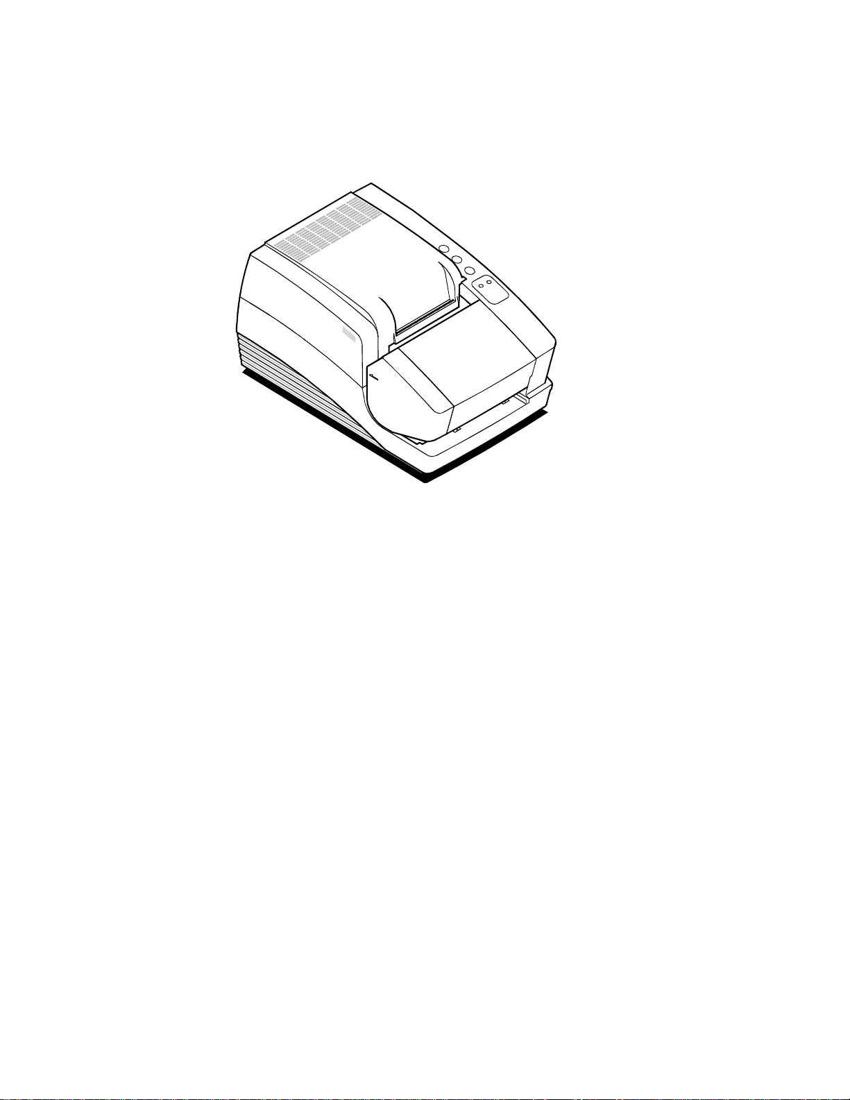
DESCRIPTION OF THE SERIES 90PLUS PRINTER
The PcOS (personal computer, point-of-sale) Series 90PLUS printer is a stand-alone, 40-column, highspeed impact printer. The Series 90PLUS printer performs a variety of functions in a point-of-sale
environment and is available in the following models:
♦ Model 91PLUS: Receipt only
♦ Model 92PLUS: Receipt and Journal
♦ Model 93PLUS: Receipt, Journal, and Slip/Validation
♦ Model 94PLUS: Receipt and Slip/Validation
SERIES 90PLUS MODELS
Each of the four models in the Series 90PLUS line of printers has its own unique set of features.
PcOS Model 91PLUS Receipt Printer
The Model 91PLUS is a receipt printer used for applications requiring high-speed printing of
receipts and single-line validation.
♦ 300 characters per second bidirectional printing
♦ 42-column printing at 15 characters per inch
Page 15

Product Information
PcOS Model 92PLUS Receipt and Journal Printer
The Model 92PLUS is a receipt and journal printer used for applications requiring a transaction
audit trail (journal) in addition to high-speed printing of receipts and single-line validation.
♦ 300 characters per second bidirectional printing
♦ 42-column printing at 15 characters per inch
♦ Journal take-up
PcOS Model 93PLUS Receipt, Journal, and Slip/Validation Printer
The Model 93PLUS is a receipt, journal, and slip/validation printer used for applications
requiring up to 17 lines of print on inserted forms such as checks (in validation mode) or charge
slips, guest checks, or personal checks (in slip mode). In addition, it provides the same high-speed
journal and receipt printing as the Model 92PLUS.
♦ 300 characters per second bidirectional printing
♦ 42-column printing at 15 characters per inch
♦ Journal take-up
♦ Form insertion sensor
♦ 17-line validation
♦ Front slip insertion
5
PcOS Model 94PLUS Receipt and Slip/Validation Printer
The Model 94PLUS is a receipt and slip/validation printer used for applications requiring up to
17 lines of print on inserted forms such as checks (in validation mode) or charge slips, guest
checks, or personal checks (in slip mode). It does not include the journal take-up assembly.
♦ 300 characters per second bidirectional printing
♦ 42-column printing at 15 characters per inch
♦ Form insertion sensor
♦ 17-line validation
♦ Front slip insertion
Page 16

Series 90PLUS Maintenance Manual
6
STANDARD FEATURES
The following features and items are standard on all Series 90PLUS printers:
♦ Centronics parallel interface with 2K buffer
♦ Internal international power supply (95 to 265 VAC)
♦ Operating controls and lights
Power ON/OFF switch and indicator
Paper feed button
Forms release button
Resume button
Alarm and form LED’s
♦ Paper-low sensor
♦ Operator controlled self-test
♦ Cash drawer connector (RJ12) and driver (24V, 1.5 amp pulse for approximately 150 ms;
drawer open/closed status reporting)
♦ Nine-pin stored energy print head
♦ Short line-seeking logic
♦ Characters and graphics
Lowercase characters with descenders
300 characters per second bidirectional printing
42-column printing at 15 characters per inch
Emphasized and enhanced print
IBM compatible all-points-addressable (APA) graphics
♦ Software controlled vertical spacing
♦ Snap-on ribbon cassette
♦ Steel receipt tear-off bar
OPTIONAL FEATURES
The optional features either replace a standard feature or enhance the operation of the printer. All
optional features are installed at the factory and must be selected when the printer is ordered.
♦ RS-232C serial communication interface
♦ RS-422 serial communication interface
♦ Journal cover lock
♦ Custom colors and logo
Page 17

Product Information
TECHNICAL SPECIFICATIONS
PRINTING SPECIFICATIONS
♦ Printing method impact dot matrix
♦ Head wire arrangement 9 pins in line
♦ Print wire diameter 0.012 inch (0.34 mm)
♦ Print wire pitch 0.013 inch (0.35 mm)
♦ Print directions bidirectional, logic-seeking
♦ Print zone 2.80 inches (71.12 mm)
PRINT CHARACTERISTICS
The Series 90PLUS printer prints characters in a variety of pitches as shown in the following table.
Each pitch can also be printed in a variety of styles affecting the appearance of the characters and the
speed of the printer.
7
For information about programming the printer to print a particular pitch or style, please refer to the
Programmer’s Guide. You can order the Programmer’s Guide from Ithaca Peripherals. See
“Contacting Ithaca Peripherals” on page 1.
Pitch (in characters per inch) Maximum Characters per
Line
8 22 250
10 28 270
12 32 300
15 42 300
17.1 (condensed) 48 300
20 (super-condensed) 56 300
24 (super-condensed) 66 300
4 (double-wide) 11 150
6 (double-wide) 16 150
7.5 (double-wide) 21 150
8.5 (condensed, double-wide) 24 150
10 (condensed, double-wide) 28 150
Characters per Second
12 (super-condensed, double-wide) 33 150
Page 18

Series 90PLUS Maintenance Manual
8
RELIABILITY
♦ Mean time between failure 30,000 hours (Model 91PLUS)
(except print head)
♦ Print head life 200 million characters
♦ Mean time to repair 15 minutes
DIMENSIONS
♦ Width 7.30 inches (185.42 mm)
♦ Length 12.25 inches (311.15 mm)
♦ Height 6.00 inches (152.40 mm)
WEIGHT
♦ Approximate weight 10 pounds
♦ Approximate shipping weight 13 pounds
POWER REQUIREMENTS
The Model 90PLUS printer is designed to b e AC self-powered in domestic and international markets.
The printer is equipped with a universal, input power supply that is designed to operate worldwide
without modification.
Supply
Voltage
Rating (VAC)
100 - 240 90 - 264 47 - 63 45 0.08 @ 120VAC
Supply
Voltage
Range (VAC)
Frequency
(Hz)
Rated Power
(watts)
Current Idle
(amps)
0.04 @ 240VAC
Current
Printing (amps)
0.9 @ 120VAC
0.4 @ 240VAC
ENVIRONMENTAL CONDITIONS
The printer will run its best when stored and operated in an environment that meets the following
temperature and humidity conditions:
♦ Operating temperature 0° to 50°C (32° to 122°F)
♦ Storage temperature -10° to +60°C (-14° to +140°F)
♦ Operating relative humidity 10% to 90% (noncondensing)
♦ Storage relative humidity 5% to 90%
Page 19

Product Information
COMMUNICATION INTERFACES AND CASH
DRAWER CONNECTORS
SERIAL CABLE
Cable Requirements
The PcOS Series 90PLUS printer requires an RS-232C shielded cable, no more than 50 feet long.
The cable must be UL and CSA approved.
RS-232C Communication
The RS-232C interface uses the following protocol and communication characteristics:
♦ Up to 19.2K baud
♦ Up to 6K buffer
♦ Ready/Busy or XON/XOFF protocol
♦ Communications diagnost i c mode
9
Pin Assignments for 9-pin Printer Connector
Pin Name Description
1 DCD Data carrier detect
2 RX Receive data
3 TX Transmit data
4 DTR Data terminal ready
5 GND Signal ground
6 DSR Data set ready
7 RTS Request to send
8 CTS Clear to send
9 SSD Secondary data
Serial Cable Configurations
The following cable configurations are for different host requirements.
Serial PC to Series 90PLUS (null modem)
Use the Ithaca Peripherals cable, part number 10-2020, for PcOS Series 90PLUS printers
connected to PC’s or PS/2’s with 9-pin serial ports.
Page 20

Series 90PLUS Maintenance Manual
10
Nine-pin
Female
PC
DTR
DSR
DCD
TXD
RXD
GND
RTS
CTS
PN 10-2020
4
6
1
3
2
5
7
8
Nine-pin
Female
Printer
DTR
DSR
DCD
TXD
RXD
GND
RTS
CTS
4
6
1
3
2
5
7
8
Serial AT to Series 90PLUS (Null Modem)
Use the Ithaca Peripherals cable, part number 10-2021, for PcOS Series 90PLUS printers
connected to PC’s or PS/2’s with 25-pin serial ports.
Twenty-five-pin
Female
PC
DTR
20
DSR
6
DCD
8
TXD
2
RXD
3
GND
7
4
RTS
5
CTS
PN 10-2021
Nine-pin
Female
Printer
DTR
DSR
DCD
TXD
RXD
GND
RTS
CTS
4
6
1
3
2
5
7
8
PARALLEL CABLE
Cable Requirements
The PcOS Series 90PLUS printer requires a 25-pin male D-shell connector at the printer. To
connect the printer to most PC’s, use Ithaca Peripherals part number 253-9800007, 25-pin male to
25-pin male parallel interconnect cable.
Page 21
Product Information
Pin Assignments
Pin(s) Signal Description Direction
1 STROBE Clock data to printer Host to printer
2 through 9 D0 - D7 Data Host to printer
10 ACK\ Printer accepted data Printer to host
11 BUSY Printer is busy Printer to host
12 PE Paper out/status Printer to host
13 SLCT Printer selected Printer to host
14 AUTOFD Autofeed paper Host to printer
15 ERR\ Printer error Printer to host
16 INIT\ Initialize the printer Host to printer
17 SLIN Select printer Host to printer
18 through 25 GND Ground
11
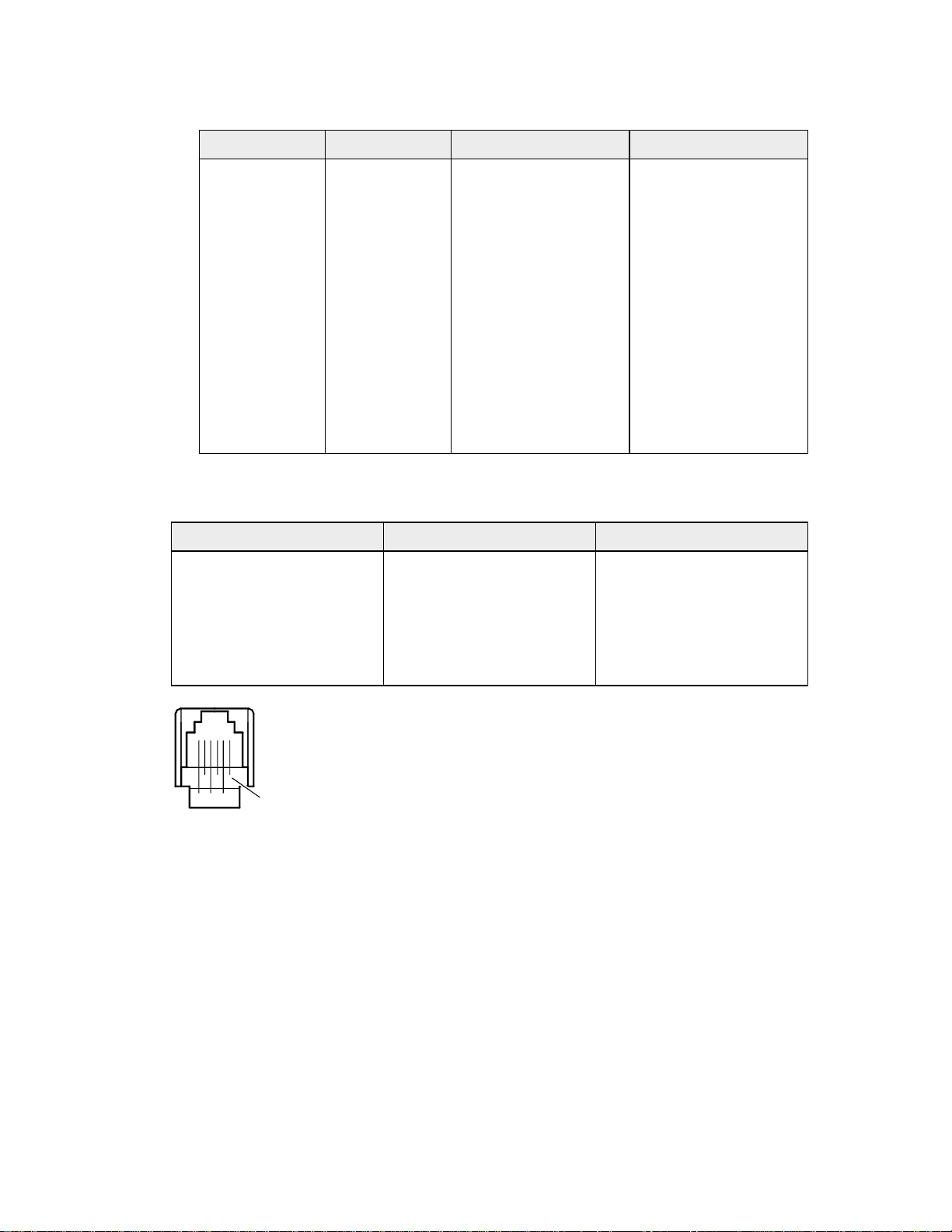
CASH DRAWER PIN ASSIGNMENTS
Function Drawer 1 Drawer 2
Drawer Drive + Pin 4 Pin 4
Drawer Drive - Pin 5 Pin 1
Status Signal Pin 2 Pin 2
Status Ground Pin 3 Pin 3
Frame Ground Pin 6 Pin 6
Pin 1
Page 22

Series 90PLUS Maintenance Manual
12
Page 23

CLEANING AND
ADJUSTMENTS
CLEANING THE PRINTER
Remove paper dust periodically by using a vacuum cleaner or air compressor.
Caution: Do not use alcohol or petroleum-based chemicals to clean the printer as these will damage
the plastic parts. The carriage rack is particularly sensitive and will be permanently damaged if
exposed to these chemicals. Take special care not to get the cleaner on any electronic components.
Cleaning and Adjustments
13
None of the internal parts of the printer require lubrication or routine maintenance. Apply a common
cleaner such as fantastik
keypad.
®
or Formula 409® to a damp cloth and gently wipe the surface of the printer and
MAKING ADJUSTMENTS
The adjustments described in this section are required only to correct print head drag or print quality flaws.
If the print density on a print sample is consistent from top to bottom and the print head does not drag, no
adjustment is necessary. If the print head drags, adjust the platen gap for the thickness of paper being used.
If the print sample is inconsistent, adjust the print head parallelism.
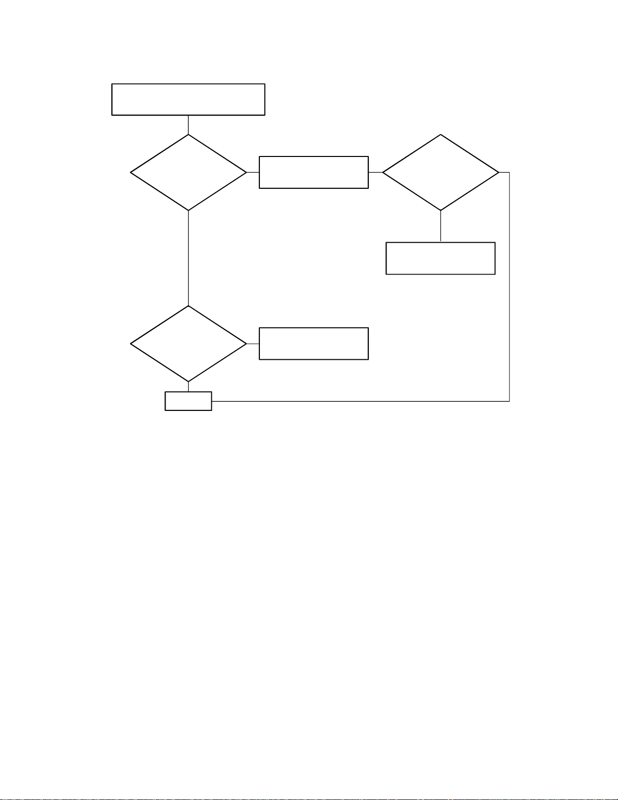
DIAGNOSING THE PRINT QUALITY
Use the flowchart on the following page to determine which procedure to use to correct a specific print
problem.
Page 24
Series 90PLUS Maintenance Manual
14
Print Quality Diagnosis.
Examine print sample.
Prints
too
light?
No
Prints on
either top or bottom, but
not both?
No
End
Yes
Replace ribbon.
Check parallelism.
Still
light?
Yes
Check platen gap.
NoYes
Note: For additional print problems not covered in this flow chart, refer to the troubleshooting chart
on page 55.
NECESSARY TOOLS
The following list provides the tools needed to adjust the platen gap.
♦ #1 Phillips screwdriver
♦ Thickness gauge: 0.016 inch (0.406 mm)
♦ Paper clip
Caution: Using the wrong tools may cause personal injury or printer damage. Be sure to use the
proper tools when maintaining or servicing the Series 90PLUS printer.
Page 25
Cleaning and Adjustments
15
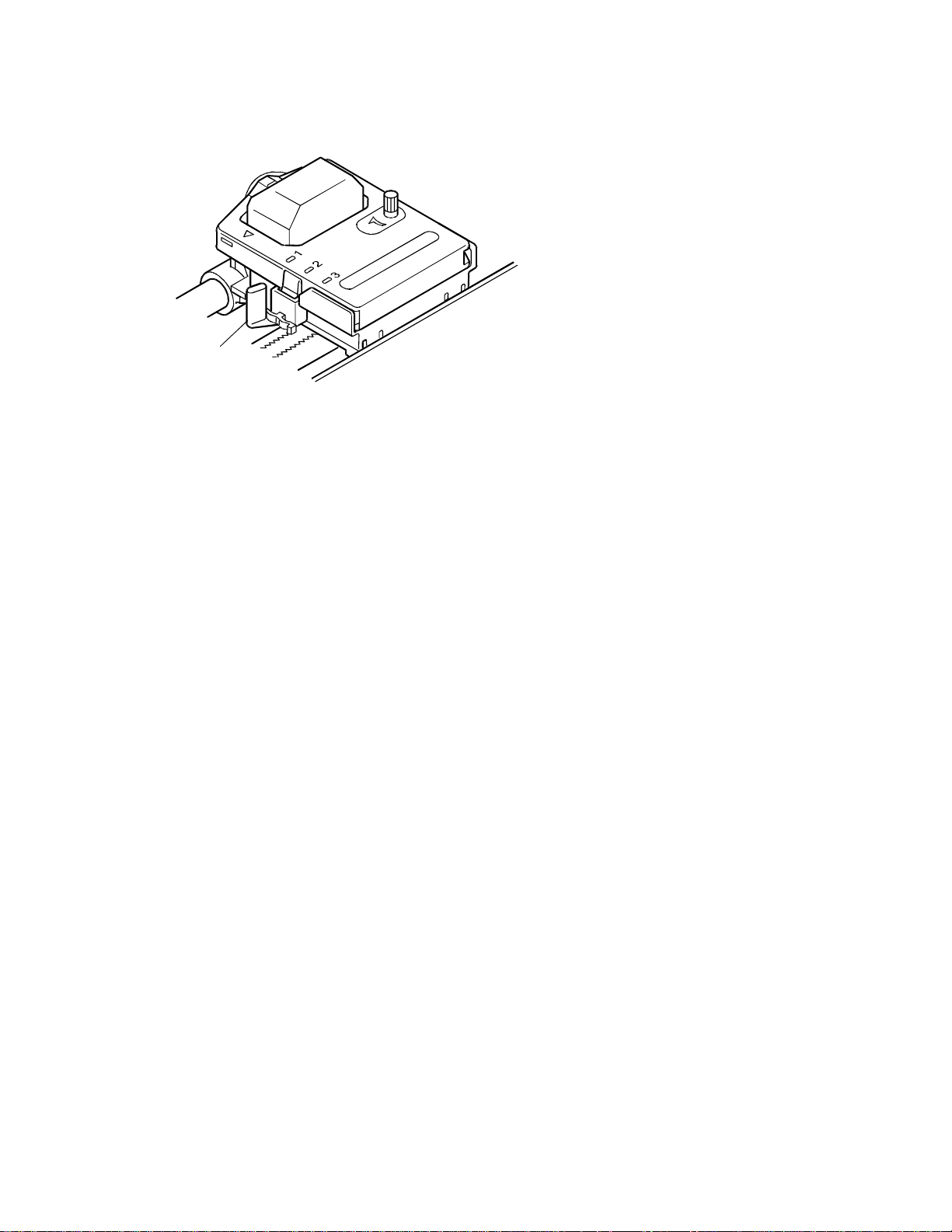
ADJUSTING THE PLATEN GAP
Blue
Lever
The gap between the print head and the platen can be adjusted to accommodate the thickness of
different paper. If the gap is not set properly, the characters may smudge, the print head may jam, and
the density of the characters may be less than ideal.
Adjust the print head gap by moving the blue lever, located to the left of the ribbon cassette, to one of
three positions.
Set the gap to one of the following:
♦ Position 1 One-ply paper
♦ Position 2 Two-ply paper
♦ Position 3 Three-ply paper
Page 26
Series 90PLUS Maintenance Manual
16
ADJUSTING THE PLATEN PARALLEL TO TH E PRINT HEAD
1
3
4
5
6
2
1. Turn off the printer.
2. Remove all paper from the printer.
3. Remove the ribbon cassette (1).
4. Set the range adjustment lever (2) to position 1 (towards the rear of the printer). The range
adjustment lever (2) is the blue lever on the print head (4).
5. Sight along the length of the platen (3) from the side of the printer to observe the parallelism
of the air gap between the platen (3) and the print head (4).
6. Press down on the outer ring of the adjusting gear (6) with the straightened end of a paper
clip, and turn the adjusting screw (5) with a #1 Phillips screwdriver until the gap measures
0.016 ± 0.003 inch (0.406 ± 0.0762 mm).
Page 27

Assembly and Disassembly
ASSEMBLY/DISASSEMBLY
PRECAUTIONS FOR DISASSEMBLY
Before disassembling any part of the printer, be sure the power is turned off. Disconnect the AC power
cord, the communication cable, and the cash drawer cables.
Caution: The controller board and PC board keypad can easily be damaged by static electricity.
Observe ESD precautions. Wear a grounded wrist strap, and use a static mat or other protected work
surface. Do not place the printed circuit boards directly on the printer or floor.
NECESSARY TOOLS
The following list provides the necessary tools for properly maintaining the Series 90PLUS printer.
♦ Screwdrivers
#0 Phillips
#1 Phillips
#2 Phillips
Small flat blade
Large flat blade
♦ Nut driver
3 mm
♦ Miscellaneous
Thickness gauge: 0.016 inch (0.406 mm)
Hobby knife
Small needle-nose pliers
17
Caution: Using the wrong tools may cause personal injury or printer damage. Be sure to use the
proper tools when maintaining or servicing the printer.
Page 28
Series 90PLUS Maintenance Manual
18
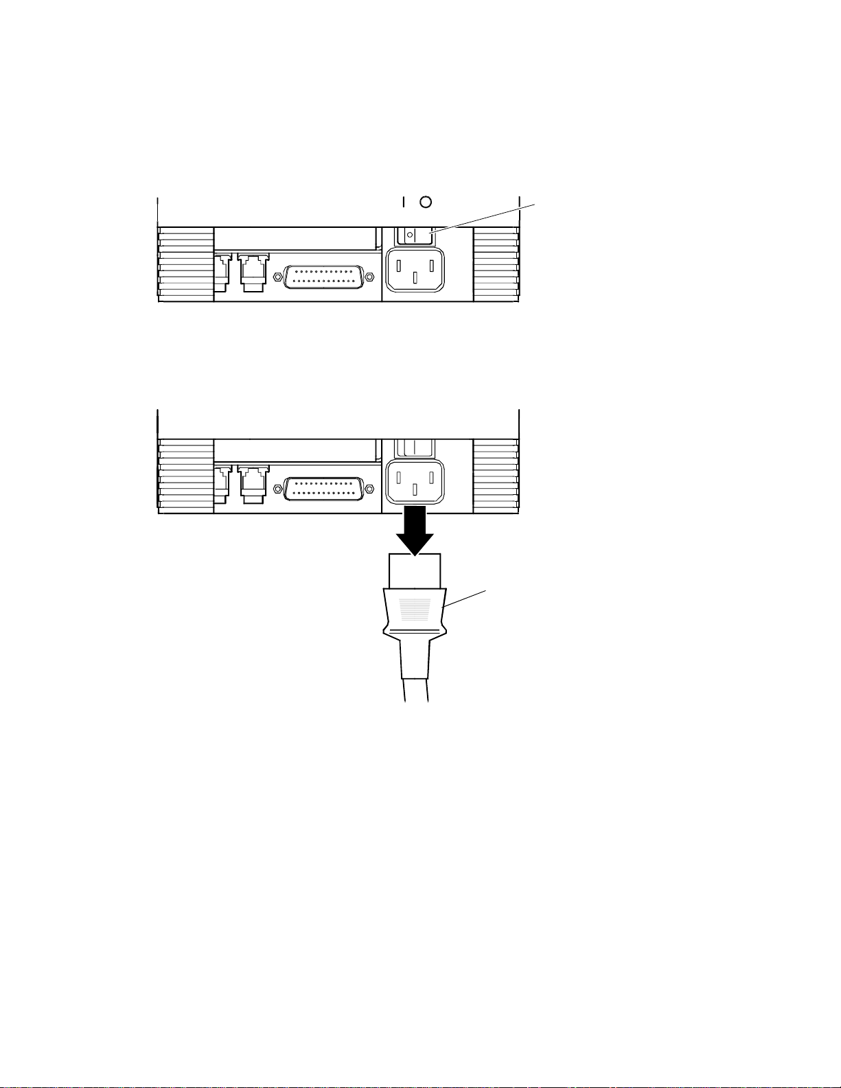
DISCONNECTING THE POWER CORD
Caution: The printer must be grounded through the three-prong power connector. Do not use a
ground-defeating adapte r.
On Off
Backof
Prin ter
1. Be sure the power switch is turned off.
Power
Switch
Back of
Printer
Power
Cord
Disconnect the external AC power source and the power cord from the power socket located on
2.
the back of the printer.
Page 29
Assembly and Disassembly
19
DISCONNECTING THE COMMUNICATION CABLE
Depending on the interface your system uses, either disconnect the serial or parallel communication cable
from the appropriate connector on the back of the printer.
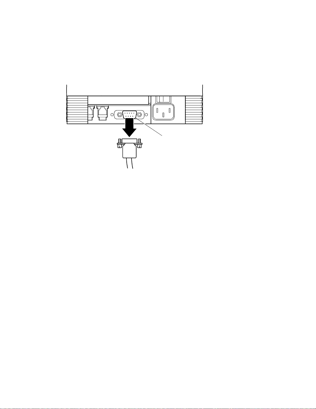
DISCONNECTING THE SERIAL CABLE
Back of
Printer
9-pin Serial
Interface Connector
1. Turn off the printer and the host system or PC.
2. Loosen the two mounting screws on each side of the cable connector.
3. Disconnect the 9-pin serial interface cable from the connector located on the back of the
printer.
Refer to “Communication Interfaces and Cash Drawer Connectors” on page 9 for
information on the serial cable requirements.
Page 30

Series 90PLUS Maintenance Manual
20
DISCONNECTING THE PARALLEL CABLE
Back of
Printer
1. Turn off the printer and the host system or PC.
25-pin Parallel
Interface Connector
2. Loosen the two mounting screws on each side of the cable connector.
3. Disconnect the 25-pin parallel interface cable from the connector located on the back of the
printer.
Refer to “Communication Interfaces and Cash Drawer Connectors” on page 9 for
information on the parallel cable requirements.
DISCONNECTING THE CASH DRAWER CABLES
Cash Drawer
Connector 2
Backof
Printer
Cash Drawer
Connector 1
1. Turn off the printer.
2. Disconnect the cash drawer cables from the connectors located on the back of the printer.
Adapters are available for connecting cash drawers equipped with BNC-style connectors. (A
modular, telephone-style connector is standard). If you need an adapter, contact the Technical
Support Department at Ithaca Peripherals. See “Contacting Ithaca Peripherals” on page 1.
Page 31

Assembly and Disassembly
21
REMOVING THE RIBBON CASSETTE
Grasp both sides of the cassette. Lift and rock the cassette towards you. Do not pull the cassette straight up.
INSTALLING THE RIBBON CASSETTE
Cassette
Print head
Tabs
Carriage
Groove
1. Holding the ribbon cassette with the Mylar guide facing away from you, insert the front of the
cassette into the carriage.
Note: It is important to fit the front edge of the ribbon cassette into the carriage first. Do not place
the ribbon cassette flat on the carriage.
Print head
Tab
Ribbon
Cassette
Clamp
Carriage
Rock the ribbon cassette forward, toward the print head, and then press down on it until the
2.
tabs on the cassette snap into the clamps on the carriage.
Page 32

Series 90PLUS Maintenance Manual
22
Tighten the ribbon by turning the knob on the cassette clockwise.
3.
Close the cassette cover.
4.
Turn the printer back on (if already installed).
5.
Knob
Cassette
Page 33

PRINT HEAD
Replace the print head when the characters are consistently misprinting.
REMOVING THE USED PRINT HEAD
Caution: The print head can get very hot.
On Off
Backof
Print er
1. Turn off the printer, and allow the print head to cool for at least three minutes before
replacing it.
Assembly and Disassembly
Power
Switch
23
2. Open the cassette cover.
3. Remove the ribbon cassette.
Cassette
Cover
Page 34

Series 90PLUS Maintenance Manual
24
Note: In the following illustrations, the heat sink is not shown for clarity.
4. Open the print head clip by grasping the tab on the right side of the clip and rotating it from
right to left.
5. Lift the print head straight up out of the carriage.
Page 35

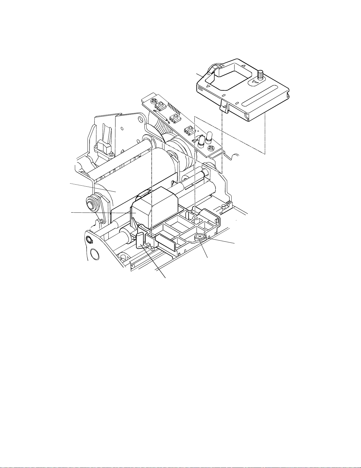
INSTALLING THE NEW PRINT HEAD
Note: In the following illustration, the heat sink is not shown for clarity.
Assembly and Disassembly
25
1. Slide the black wire guide on the back of the print head into the slot on the carriage. Make
sure the tabs on the wire guide hold the print head against the carriage.
2. Align the PC board on the bottom of the print head with the receptacle on the carriage.
3. Press the print head into the carriage. Do not force the PC board into the receptacle. Make
sure it is lined up properly.
4. Close the print head clip by rotating it from left to right and latching it into place.
5. Replace the ribbon cassette, and then close the cassette cover.
Page 36

Series 90PLUS Maintenance Manual
26
REMOVING THE COVERS
3
1
5
6
4
8
1. Unlock the optional journal lock (1) located on the right cover (2).
2. Open the paper cover (3) until it unsnaps from the base cabinet (6).
2
7
3. Remove the take-up spindle (4).
4. Remove the clip (5). Use needle-nose pliers to squeeze the open ends on the clip, and carefully
pull it out. Move the back corner of the right cover (2) to the right until the star stud clears the
tower on the base cabinet (6). Rotate the back corner up and to the front until it is free from the
base cabinet.
5. Open the cassette cover (7). Pull the hinge pin (8) out from the right, and remove the cassette
cover.
Page 37

10
Assembly and Disassembly
6
10
9
27
11
12
13
8
13
6. From the bottom of the mechanical/electrical base assembly (8), insert a flat blade screwdriver
through the holes in the front, and unlatch the tabs (13 ) holding the cabinet bezel (9) to the base
cabinet (6). Push on the left side of the cabinet bezel (9) to free the pin from the cabinet base.
7. Remove the four screws (10) holding the base cabinet (6) to the mechanical/electrical assembly
(8). Lift the back of the base cabinet up and slide forward.
8. Models 92PLUS and 93PLUS, disconnect the take-up harness (11) from the take-up extension
cable (12).
Page 38

Series 90PLUS Maintenance Manual
28
TAKE-UP MOTOR ASSEMBLY KIT
Models 92PLUS and 93PLUS
2
3
1
1. Remove the covers. See page 26.
2. Remove the E-ring (1) and slide off the arm (2) from the take-up motor assembly (3).
Page 39

Assembly and Disassembly
29
4
5
3
3. Remove the screw (4) holding the take-up assembly (3) to the base cabinet (5).
4. Release the take-up motor assembly (3) from the base cabinet (5). Move the bottom of
the take-up motor assembly to the right until it clears the tab on the back wall of the base
cabinet.
Page 40

Series 90PLUS Maintenance Manual
30
MECHANICAL BASE ASSEMBLY
9
2
10
11
4
1
1
6
8
1
1
7
9
5
3
Page 41

Assembly and Disassembly
31
1. Remove the covers. See page 26.
2. Remove the four screws (1), two in front and two in back, holding the mechanical base (2) to the
electronic base assembly (3).
3. Lift the mechanical base (2), and disconnect the following harnesses from the controller board
assembly (4): cam plate motor (6); head cable (5); slip-in sensor (7); paper-low sensor (8); takeup motor extension (9); keypad (10); and receipt line feed stepper-motor (11). Refer to the chart
below for connector locations on the controller board.
4. Remove the slip-in sensor harness (7) and paper-low sensor harness (8) from the tabs on the left
and back of the insulator.
5. Remove the receipt line feed stepper-motor harness (11) from the tab on the right side of the
insulator.
Type of Harness Controller Board Location
Head cable CN8
Cam plate motor CN7
Slip-in sensor CN9
Paper-low sensor CN15
Take-up motor extension
(Models 92PLUS and 93PLUS)
Keypad CN5
Receipt line feed stepper-motor CN3
CN4
Page 42

Series 90PLUS Maintenance Manual
32
KNIFE DISASSEMBLY
1
See Detail B.
5
17
14
6
15
16
4
3
12
7
10
20
8
9
See Detail B.
11
18
13
2
Page 43

Assembly and Disassembly
14
Assemble with curve
faci ng t he stud
shoulder as shown.
33
9
Stud shoulder
Detail B
Scale 2 = 1
19
Approximate location
of f er r ite bead.
Detail A
Bottom view
Connecting rod must be
assembled in this orientation.
Detail C
Caution: The knife blade is extremely sharp.
1. Turn the cutter assembly upside down, remove the screw (12), and pull out the knife guide (2). If
necessary unsnap and remove the tear-off (13).
2. Remove the screw (18) and the E-ring (11), and separate the knife plate assembly (3) from the
knife frame.
3. Remove the connecti ng rod (7) a nd the compound ge ar (17) fr om the knife pin ( 6). Remove t he
knife gear (5) and the knife pin from the knife frame.
4. Disconnect the knife motor connector (16) from the PCB assembly (15). Unthread the knife motor
harness from the wire retainer (19), and remove the knife motor.
5. Pull the PCB assembly out of the knife frame (1).
6. To remove the knife blade (4), unscrew the drive stud (9). This will also release the Teflon film
(10), spring washer (14), knife slider (8), and shear blade (20).
Installation notes
1. Position the ferrite bead on the knife motor harness as shown in Detail A.
2. Refer to Detail C for the correct orientation of the connecting rod. Lubricate the four points on the
knife frame with Teflon Anti-Seize Lube.
3. Install the spring washer with the curve facing the stud shoulder as shown in Detail B.
4. The slider must be replaced if disassembled. The stud must be retorqued to 4.5 ± 1 in. lbs. and
then loosened one-quarter turn.
Page 44

Series 90PLUS Maintenance Manual
34
25-PIN PARALLEL INTERFACE CABLE
3
1
4
2
1. Remove the mechanical base assembly. See page 30.
2. Disconnect the 25-pin parallel interface cable (1) from the connector, CN13, on the controller
board (2).
3. Unscrew the two jack screws (3) holding the cable to the electronic base (4).
Page 45

9-PIN SERIAL INTERFACE CABLE
3
6
5
Assembly and Disassembly
4
7
7
35
1
2
1. Remove the mechanical base assembly. See page 30.
2. Disconnect the 9-pin serial interface cable (1) from the connector, CN14, on the controller board
(2).
3. Unscrew the two jack screws (3) holding the cable to the adapter plate (4).
4. Remove the adapter plate (4) from the electronic base (5) by unscrewing the two screws (6) from
the two nuts (7).
Page 46

Series 90PLUS Maintenance Manual
36
CASH DRAWER HARNESSES
1
3
4
2
1. Remove the mechanical base assembly. See page 30.
2. Disconnect Cash Drawer Harness #1 (1) from the connector, CN11, on the controller board (2).
3. Pull the harness up and out of the electronic base assembly (3).
4. Disconnect Cash Drawer Harness #2 (4) from the connector, CN12, on the controller board (2).
5. Pull the harness up and out of the electronic base assembly (3).
Page 47

POWER SUPPLY ASSEMBLY
1
2
Assembly and Disassembly
4
3
37
3
6
3
5
1. Remove the mechanical base assembly. See page 30.
2. Disconnect the DC power harness (1) from the connector, CN10, on the controller board (2).
3. Unscrew the three screws (3) holding the power supply (4) to the electronic base (5).
4. Depress and push t he power assembly standoff (6 ) through the side of the electronic base (5).
5. Lift the power supply assembly (4) up, and disconnect the power switch harness (7).
7
1
Page 48

Series 90PLUS Maintenance Manual
38
POWER SWITCH AND AC INLET ASSEMBLY
1
2
3
4
6
5
7
6
White
Black
Black
White
Green with
Reference Wire Orientation
Yellow Stripe
1. Remove the power supply. See page 37.
2. Unplug the AC inlet assembly wires (7) from the power switch assembly (1).
3. Remove the power switch assembly (1) by squeezing the tabs on the sides of the switch and
pushing it out of the electronic base (2).
4. Unscrew the nut (3) ho l ding the ground wire ( 4) to the stud (5) on the electronic base (2). Remove
the lock washer (6) from the stud.
5. Remove the AC inlet assembly (6) by squeezing the tabs on the top and bottom of the assembly.
Page 49

CONTROLLER BOARD ASSEMBLY
1
8
Assembly and Disassembly
39
5
2
3
8
8
7
1. Remove the mechanical base. See page 30.
4
6
2. Disconnect the DC power harness (1), left cash drawer harness (2), right cash drawer harness (3),
and the interface cable (4) from the connectors on the controller board (5). See the chart below for
locations on the controller board.
3. Remove the snap rivet (6) from the electronic base assembly (7). To remove the snap rivet, locate
it on the bottom of the electronic base, push the center pin up into the outer jacket, depress the
tabs on the oute r jacket, and push it through the e l ectronic ba se.
4. Remove the three screws (8) holding the controller board (5) to the electronic base assembly (7).
Type of Harness Controller Board Location
DC power CN10
Left cash drawer (Cash Draw Harness #1) CN11
Right cash drawer (Cash Draw Harness #2) CN12
Interface cable (25-pin parallel) CN13
Interface cable (9-pin serial) CN14
Page 50

Series 90PLUS Maintenance Manual
40
KEYPAD PC BOARD
1
1
2
4
5
2
4
3
1. Remove the mechanical base assembly. See page 30.
2. Remove the two screws (1) holding the keypad PC board (2) to the mechanical base assembly (3).
3. Lift the keypad PC board (2) from the mechanical base assembly (3), and disconnect the keypad
harness (4).
4. Cut the Ty-wrap (5) to remove the keypad harness (4).
Installation note
3
When replacing the Ty-wrap (5), the knot and trimmed end should be positioned towards the
inside of the base wall.
Page 51

CARRIER/CAM PLATE
Models 93PLUS and 94PLUS
7
8
Do not include
keypad harness in
Ty-wrap bundle.
Assembly and Disassembly
41
2
1
5
6
8
4
3
1. Remove the mechanical base assembly. See page 30.
2. Disassemble the cam sensor flag (1) from the carrier/cam assembly (2), located under the
mechanical base assembly (3). To remove, securely grab the narrow portion of the flag
and pull down. Tip the flag to the right and wiggle out to the left.
3. Remove the slip-stop sensor flag or bank validation flag (4) from the carrier/cam
assembly (2).
4. Remove the screw and pull off the magnet mounting bracket (6).
Page 52

Series 90PLUS Maintenance Manual
42
2
3
5. Release the lock tabs, and slide the carrier/cam assembly (2) backwards until it is
released from the mechanical base assembly (3).
6. Carefully pull the cables (7) out of the mechanical base assembly (3).
Installation note
1. To reinsert the cam sensor flag, wiggle in the flag on the left side. Lift up on the flag and
snap into place.
Page 53

Models 91PLUS and 92PLUS
Assembly and Disassembly
1
43
2
1. Remove the mechanical base. See page 30.
2. Release the lock tabs, and slide the carrier/cam assembly (1) backwards until it is
released from the base (2).
Page 54

Series 90PLUS Maintenance Manual
44
CAM PLATE
Models 93PLUS and 94PLUS
2
4
3
1
4
5
1. Remove the carrier/cam plate. See page 41.
2. Partially remove the pin (1) to the left until the motor shroud (2) is free from the cam
plate (5).
Caution: Do not pull the pin all the way out or the gear drive will not be
functional.
3. Separate the tabs and lift out the cam plate motor (3).
4. The cam lobes must face downward (toward the cam plate). Rock the carrier assembly
forward (4), and slide it backwards until is released from the cam plate (5).
Page 55

Assembly and Disassembly
45
7
6
1
5
8
5. Push back on the tab behind the cam shaft (6), and lift the cam shaft out of the cam plate
(5).
6. Slide the cam shaft gear (7) off the left end of the cam shaft (6).
7. Slide the pin (1) to the left, and remove the compound gear (8).
Page 56

Series 90PLUS Maintenance Manual
46
Models 91PLUS and 92PLUS
1. Remove the carrier/cam plate. See page 41.
2. Slide the carrier assembly (2) backward until it is released from the cam plate (1).
Page 57

CARRIER ASSEMBLY
Assembly and Disassembly
47
3
12
6
7
2
14
5
1
8
4
11
12
13
14
15
13
Shown
Removed
for Clarity
11
2
10
9
Ty Warp
.50 Approx.
Page 58

Series 90PLUS Maintenance Manual
48
1. Remove the cam plate. See page 44.
2. Unsnap the receipt roller (1) from the forms comp carrier (2).
3. Rotate the bearings (3 and 4) on each side of the platen assembly (5) forward until the platen
assembly can be lifted out.
4. Remove the left platen bearing (3) from the platen assembly (5).
5. Lift the pressure shaft (6) up, and slide it through the hole on t he right side of the forms comp
carrier (2).
6. Unsnap the spring plate (7) from the forms comp carrier (2).
7. Models 93PLUS and 94PLUS only. Unsnap the forms comp springs (8) from the forms comp
carrier (2).
8. Cut the Ty-wrap (9) securing the motor wires and sensor harnesses (11 and 14).
9. Unscrew the two screws (12) and two hex nuts (13) holding the line feed motor assembly (15) to
the forms comp carrier (2).
10. Unsnap the paper-low sensor (14) from the forms comp carrier (2) by pushing the tab to the right.
11. Models 93PLUS and 94PLUS only. Unsnap the forms-in sensor (11) assembly from the forms
comp carrier (2) and slide out.
Page 59

Assembly and Disassembly
REMOVING THE PRINT MECHANISM ASSEMBLY
49
3
See Installation Note.
5
1. Remove the carrier/cam plate. See page 41.
2. Remove the carriage shaft screw (1) from the right side of the base assembly (2).
2
1
4
3. Remove the screw (3) holding the print mechanism (5) to the base assembly (2).
4. Remove the screw (4) holding the carriage rail to the base assembly (2).
5. Remove the head cable tape from the bottom of the print mechanism frame.
6. Lift the print mechanism (5) o ut of the ba se assembly (2). Gently pull the he ad cabl e through the
slot.
Installation note
When installing the screw (3), torque to 5 ± 1 inch per pound.
Page 60

Series 90PLUS Maintenance Manual
50
PRINT MECHANISM ASSEMBLY
1. Remove the print mechanism assembly. See page 49.
2. Lift the left side of the carriage rail (15), and slide it out of the print mechanism frame (3).
3. Slide the carriage shaft (14) to the right, and pull out of the print mechanism frame (3) and carriage
assembly (16).
4. Remove the carriage assembly (16). Be careful when pulling the ribbon cable out of the frame.
5. Release the tab on the left side of the frame, and lift out the space rack (5).
6. Remove the idler gear (7) from the frame by squeezing the tabs together with pliers and pushing
the gear to the right.
7. Remove the two clips (13) from the validation shaft assembly (12), and slide the validation shaft
assembly right until it is free from the frame. Slide the feed-roll bearing (2) out of the frame.
8. Snap the slip-drive shaft (4) out of the actuator (9).
9. Remove the actuator (9) and idler gear (1) by removing the small pin (6) from the left side of the
frame and sliding the large pin (8) out of the frame and idler gear (1).
10. T urn the print mechanism assembly upside down to remove the shaft before releasing the actuator
from the frame. Flip right-side up, and gently slide the actuator out of the frame.
11. To remove the actuator bearings (10) and actuator compression springs (11) from the actuator (9),
turn the actuator over. Rotate the bearings 90°. They will easily pop out.
Page 61

CARRIAGE ASSEMBLY
Assembly and Disassembly
51
Cut Mylar
fro m c a b le
as shown.
1. Disassemble the print mechanism assembly. See page 50.
2. Remove the print head (2). See page 23.
3. Release the four tabs holding the ribbon feed gear assembly (3) to the carriage motor assembly
(6). Use caution not to separate the ribbon feed gear assembly parts.
4. Remove the print head connector (1).
5. Remove the head cable (5) and the rubber pressure contact (4) from the bottom of the ribbon feed
gear assembly (3).
Page 62

Series 90PLUS Maintenance Manual
52
CARRIAGE MOTOR
1. Disassemble the carriage assembly. See page 51.
2. To remove the print head clamp (5), gently pry the back of the clamp over the pin on the back of
the carriage roller (3).
3. Remove the front screw (4), and take off the slider (1).
4. Remove the back two screws (4) to separate the spacer motor assembly (2) from the carriage
roller (3).
Page 63

LINE FEED MOTOR
Assembly and Disassembly
4
53
3
2
Shown
removed for
clarity
1. Remove the print mechanism assembly. See page 49.
2. Remove the line feed motor ( 2) by prying off the Tinne rman clip (1) and r emoving the hex nut
holding the motor to the base assembly (4).
1
Page 64

Series 90PLUS Maintenance Manual
54
Page 65

Troubleshooting
55
TROUBLESHOOTING
This chapter provides solutions to problems that may occur with the printer. Use the table to determine the
problem, then refer to the specified flow chart that describes the corrective action for that problem.
Following the flow charts is a section that describes checking the connection circuits and resistance for the print
head, space motor, and line feed motor.
DETERMINING THE PROBLEM
When Problem
Occurs
Trouble at power on Switches or lights do not function on the keypad, and the
Trouble during data Spacing or printing does not occur. 5
reception or printing Spacing operates normally, but printer does not print. 6
Forms handling Receipt does not line feed. 11
Description of Problem Refer to Flow
chart
carriage does not move.
Carriage does not move, and the power LED is lit. 2
Carriage does not operate normally; runaway, vibration, or
incomplete homing occurs.
Carriage homes normally, but indicator display does not
operate normally.
Printer stops printing. 7
Wrong characters are printed or some characters are not
printed.
Some dots do not print. 9
Print is not dark enough. 10
Slip does not line feed. 12
Carrier assembly does not open or close. 13
1
3
4
8
Slip will not load from the front of the printer. 14
Top validation failure occurs. 15
Page 66

Series 90PLUS Maintenance Manual
56
1
Is AC cord
fully seated?
Yes
Is primary
wiring loose or
broken?
No
Is AC switch
damaged or
open?
No
Is secondary
wiring loose or
broken?
No
Yes
Yes
Yes
Reseat AC power
cord.
Repair/replace
primary wiring
harness.
Replace AC switch.
Repair/replace
secondary wiring
harness.
No
Replace power
supply.
Voltages n ow
present?
Yes
End
No
2
Page 67

2
When the po we r i s
turned on, the
carriage does not
move.
Troubleshooting
57
No
Yes
Do LED’s
illuminate?
Yes
Can the
carriage be moved
easily by
hand?
Yes
Is the
carriage cable
damaged or
unplugged?
No
Are +40V
present at
emitter of Q14?
No
Is fuse,
F2, on the
controller board
open?
No
Yes
Replace/
reseat the
carriage cable.
Yes
2-2
Remove the
ribbon cassette.
Can the
carriage be
moved easily by
hand?
No
Is
the space rack
okay?
Yes
Remove the ribbon
feed gear assembly.
Replace the ribbon
Yes
Replace the space
No
cassette.
rack.
No
Replace the
controller board.
Replace fuse.
Can
the carriage
be moved easily by
hand?
No
Replace space motor.
Replace the ribbon
Yes
feed gear assembly.
Page 68

Series 90PLUS Maintenance Manual
58
3
When power is turned on, carriage oper ation is
abnormal; runaway, vibration, or incomplete
homing occurs.
Runaway?
No
Vibration?
Yes
Are
phase A&B
being output to US pins
75, 76 on controller
board?
Yes
Replace controller
board.
Is printer
operation
normal?
No
Yes
No
Replace controller
board.
Proceed to
No
2-2.
Is
the ribbon
feed assembly
attached
correctly?
Yes
Is
the carriage
cable broken or
unplugged?
No
Yes
Reassemble.
Replace/reseat
carriage cable.
Yes
End
No
Replace space motor
assembly.
Page 69

4
When the power is turned on,
the homing operation is
normal, but the READY LED
is flashing.
Troubleshooting
59
Flashing
green?
Yes
Is the paper
cover closed?
Yes
Is the
magnet present
in the paper
cover?
Yes
Replace the
switch assembly.
No
No
Close the paper
cover.
Flashing
orange?
Yes
Is the paper
installed in the
printer?
Yes
Replace the paper-
low sensor.
No
Flashing red
indicates printer fault.
Refer to Table 2
Fault Indicators.
No
Install paper.
Page 70

Series 90PLUS Maintenance Manual
60
During data reception, neither carriage
movement nor printing occurs.
Verify that data is
being transmitted to
5
the printer.
No
Replace controller
board.
Can self -test be
performed?
Yes
Is interface
cable connected
correctly?
Yes
Is printer
interface
configured
correctly?
Yes
No
No
Reconnect interface
cable.
Run configuration
routines.
Replace the
controller board.
Page 71

6
During data reception
and printing, carriage
motion is normal but
nothing prints.
Replace print head.
6A
Troubleshooting
61
Is print
operation
normal?
Yes
End
No
Is the ribbon
feed assembly
attached
correctly?
Yes
Is carriage
cable broken?
No
Is the contact
pin of print head
connector
deformed?
No
Yes
Yes
Reassemble.
Replace carriage cable.
Replace the connector.
No
Replace controller
board.
Page 72

Series 90PLUS Maintenance Manual
62
7
During data reception and printing,
printing stops.
Are any
LED’s
flashing?
No
Is the interface
cable connected
securely?
Yes
Replace the print head.
Is printer
operation normal?
Yes
Yes
No
Refer to Table 1 LED
No
Replace controller
Indicators.
Reconnect the
interface cable.
board.
End
Page 73

8
Wrong c haract e r s are printed, or
some characters are not printed.
Troubleshooting
63
Is interface
cable connected
properly?
Yes
Does self-test
print normally?
Yes
Is printer
configured
correctly?
Yes
Replace controller
board.
No
No
No
Connect the cable
properly.
Replace controller
board.
Run configuration
utility.
Page 74

Series 90PLUS Maintenance Manual
64
9
Some dots are not
printed.
Is the ribbon
properly
seated?
Yes
Remove the
print head.
No
Seat the ribbon.
Are any pins
broken or
misaligned?
No
Check resistance of
the print head coil.
Is resistance
approximately
20 ohms?
Yes
Proceed to
6A.
No
Yes
Replace the
print head.
Page 75

10
Print is not dark
enough.
Troubleshooting
65
Is the ribbbon
feed operating
properly?
Yes
Is ribbon wear
excessive?
No
Is head gap
set correctly?
Yes
Are power
supply
voltages
correct?
No No
Yes
No
No
Replace ribbon
cassette.
Replace ribbon
cassette.
Adjust head gap.
Replace power
supply.
Is operation
normal?
Yes
Replace ribbon feed
END
gear assembly.
Yes
Replace printhead.
Is p rinter
operation
normal?
Yes
END
No
Replace controller
board.
Page 76

Series 90PLUS Maintenance Manual
66
11
Receipt feed is not
performed.
Is paper
installed
properly?
Yes
Is receipt feed
step motor
plugged in?
Yes
Check resistance of
step motor windings.
Is resistance 6.8
ohms?
Yes
No
No
No
Install paper correctly.
Reconnect motor t o
controller board.
Replace receipt feed
step motor.
Bind in paper
feed gear
train?
No
Is fuse, F1, on
the controller
board open?
Yes
Replace fuse.
Yes
No
Correct bind
condition.
Replace controller
board.
Page 77

12
y
Slip feed is not
performed.
Troubleshooting
67
Is carrier
assembly
closed?
Yes
Do step motor
pins contact
controller
board?
Yes
Check resistance of
step motor windings.
Is resistance 70
ohms?
Yes
12A
No
No
No
Depress RELEASE
button.
Correct bent pins and
reinstall controll er
board.
Replace slip-feed st ep
motor.
Does carrier
assembl
close?
No
Proceed to
13.
Correct
operation?
Yes
No
Bind in paper
feed gear train?
No
Replace controller
board.
Yes
Correct bind condition.
Yes
End
12A
Page 78

Series 90PLUS Maintenance Manual
68
13
Carrier will not
open/close properly.
Does
carrier move when
RELEASE button is
depressed?
No
Check for 12V at
terminals of cam
plate motor when
RELEASE button is
depressed.
Yes
sensor flag
properly
installed?
Yes
Replace controller
board.
I
s
No
Correctly
install flag.
Voltage
present?
No
Motor
connections
okay?
Yes
Replace controller
board.
No
Yes
Repair motor
harness.
Unplug motor
from controller
board, and check
terminal
resistance.
Is
resistance 12
1 ohm?
±
No
Replace motor.
Yes
Check assembly for
mechanical bind
condition.
Page 79

Troubleshooting
69
14
Slip will not load from
the front of the printer.
Does
carrier assembly
open and close
properly?
Yes
Does slip
stepper motor activate
when slip is
inserted?
Yes
Yes
Is slip fed into
printer?
No
Check slip-drive shaft for
bind condition.
No
Proceed to
No
Check slip-drive
step motor.
Are
the slip-sensor
flag and spring
positioned
properly?
Yes
13.
No
Readjust sensor flag.
Check TOF sensor.
Is the
TOF sensor
okay?
Yes
Replace controller
board.
Replace controller
board.
No
Replace TOF sensor.
Page 80

Series 90PLUS Maintenance Manual
70
15
Carrier does not
operate correctly.
Does
carrier assembly
open and close
properly?
Yes
No
Proceed to
13.
Does carrier
close when form
is inserted?
No
Are
sensor flag and
spring positioned
properly?
Yes
Replace controller
board.
No
Readjust sensor flag.
Page 81

Troubleshooting
71
LED INDICATORS
There are two indicators. One is READY and the other is STATUS (Form). The READY indicator is
tricolored: red, green, or orange.
The printer can be in any of the following states.
STATE READY
Indicator
1. Ready
The printer is ready to receive data and print.
2. Printer not ready
Cover is open.
3. Ready but waiting for a form Orange (status)
Request slip form Slow flash
Request validation form Fast flash
Request form be removed Medium flash
4. Ready, but low on receipt paper Flashing orange/green OFF
5. Printer errors
Out of paper Flashing orange OFF
Slip-load failed Slow flash
Printer fault (See page 72.) Flashing red OFF
6. Menu mode Flashing orange/green/red OFF
7. Test mode Flashing red/orange OFF
8. Printer failure Orange OFF
Green OFF
Flashing green OFF
FORM
Indicator
9. Watchdog fault (printer resets)
Table 1 LED Indicators
Page 82

Series 90PLUS Maintenance Manual
72
PRINTER FAULT INDICATORS
If the printer indicates printer fault, the error is not recoverable. The printer must be restarted and may lose
information. To aid in printer troubleshooting, the RESUME key will activate an extended diagnostic
indication. This key will blink the status indicator a number of times. The number of blinks indicates the
fault.
The printer fault errors are as follows.
Faults during operation
1 Motor move time out
2 Motor move retry fault
3 Motor move fault (moved in wrong direction)
4 Space motor locked
5 Motor homing fault
6 Motor acceleration fault
7 Printing fault
8 Fault while centering
9 Forms compensation fault
Faults during Level 0 diagnostics
10 ROM check-sum failure
11 RAM failure
12 Configuration EEPROM failure
13 Processor test fault
14 EEPROM check-sum failure
Faults that can happen anytime
15 Firmware control fault (loss of program control)
Table 2 Fault indicators
After the fault code is displayed, restart the printer by pressing the RESUME and RELEASE keys
simultaneously.
If the EEPROM check-sum fault occurs (Fault Code 14), the EEPROM can be set to defaults by pressing
the RESUME and LF keys simultaneously. The printer will be functional but must be reconfigured. This
procedure is only to allow reconfiguration and not to recover printer function in the field.
If the indication is pri nte r fail ure , t he p r int co ntr o lle r is no t r unning a nd is b ei ng hel d in r ese t. If thi s fa ilur e
occurs, the printer is not functional and should be serviced.
If the printer appe ars to go through a po wer cycle by itself, the hard ware watchdog has detected a fault.
This fault is generally a hardware failure or an external interference. If the fault is a hardware failure, the
printer will continue to cycle through its diagnostics and then reset. If this happ ens, the printer must be
serviced. If the fault is caused by external interference like electrostatic discharge (ESD), the printer will
generally recover. (Note: The parallel-port INIT pin causes a soft reset.)
Page 83

CN10
CN4
CN12
CN11
CN14
CN13
CN5
CN3
Troubleshooting
73
CN7
CN15
CN9
CN8
Note: This illustration is referenced by the letters in the troubleshooting flow charts and in the
illustrations on the following three pages.
Page 84

Series 90PLUS Maintenance Manual
74
CHECKING CONNECTIONS AND RESISTANCE
PRINT HEAD
The following illustration shows the connection circuit for the print head. To check the circuit of Wire
#1 on the print head, use Pin 5, 6, or 7 and measure with a meter to Pin 14 at Location A. The
resistance should read approximately 20 ohms.
Pins at Connection Signals Pins on
Print head
Common
Wire #1
Wire #2
Wire #3
Wire #4
Wire #5
Wire #6
Wire #7
Wire #8
Wire #9
5, 6, 7
14
13
1
12
2
11
1
10
4
Rear of Print head
Page 85

Troubleshooting
75
SPACE MOTOR ASSEMBLY
The following illustration shows the connection circuit for the space motor assembly and the pins on
the space motor. The resistance should be approximately 21 ohms between pads 17 and 16, 16 and 18,
and 17 and 18 on the space motor.
Pins at Connection Signals Pins on Space Motor
V
U
W
A
B
15
14
16
LINE FEED MOTOR (SLIP)
The following illustration shows the connection circuit for the line feed motor. The resistance of each
coil should be approximately 70 ohms between pads 38 and 39, 39 and 40, 37 and 36, and 36 and 35
on the line feed motor.
Pins at Connection Signals Pins on Line Feed Motor
Phase 1
3
Common
Phase 3
Phase 2
Common
Phase 4
2
1
4
5
6
Page 86

Series 90PLUS Maintenance Manual
76
LINE FEED MOTOR (RECEIPT)
The following illustration shows the connection circuit for the line feed motor. The resistance of each
coil should be approximately 6.8 ohms.
Pins at Connection Signals Pins on Line Feed Motor
Phase 1
Phase 3
Phase 2
Phase 4
Page 87

Appendix A: Theory of Operation
APPENDIX A: THEORY OF
OPERATION
77
Page 88

Series 90PLUS Maintenance Manual
78
ELECTRICAL OPERATION
CIRCUIT OPERATION
The electrical section of the printer consists of the components shown in the above diagram.
The control board contains the microprocessor, its peripheral circuits, and all associated drive circuits
for the print head, line feed motor, slip-feed motor, journal take-up motor, cash drawers, and sensors.
The printer cont rol signals from the host system (PC or terminal) are brought direc tly to the control
board from the rear panel on the printer.
Page 89

Appendix A: Theory of Operation
MICROPROCESSOR AND PERIPHERAL CIRCUITS
MICROPROCESSOR (U1: 80C154)
The microprocessor is the nucleus of the control board. It controls the peripheral circuits.
PROGRAM ROM (U4)
The program ROM stores the control program for the printer.
PROGRAM RAM (U2)
The program RAM stores printer configuration information.
RAM (U5)
The RAM stores data such as received print information.
79
LSI (M7U042-026)
The M7U042-026 motor control LSI has the following functions:
♦ Space motor speed control
This function accelerates and decelerates the space motor in accordance with commands from
the microprocessor and controls the space motor speed in each printing mode.
♦ Dot-timing generation
This function generates the dot timing signal (/IPT), synchronized with the printing speed in
accordance with the output signals (PHASE A, B) of the encoder on the space motor, and
sends the timing information to the microprocessor.
♦ I/O ports
The input and output ports control signals in accordance with the commands input from the
microprocessor.
♦ Address latch
The address latch fastens the low-order 8-bits of the address (A0 to A7). These bits are used
as an address for read/write operations with peripheral devices.
♦ Address decoder
The address decoder decodes the address signal (A11 to A15) and sends the /RAMSEL4
signal.
Page 90

Series 90PLUS Maintenance Manual
80
INITIALIZATION
The printer is initialized when the power is turned on or when the parallel interface signal, I-PRIME, is
received from the host computer.
Initialization begins with the RSTOUT signal output from the reset circuit to reset U1 (microprocessor),
and U3 (LSI).
When reset is complete, the program starts with mode settings of U1, U3, and U5, memory (ROM and
RAM) check, AM initialization, and carriage homing. The program finally establishes the interface signals
(output of ACK signal, BUSY signal, etc.), lights the select indicator, and informs the host system that the
printer is ready for data reception (in the data reception wait state). This completes the initialization
routine.
INTERFACE CONTROL
PARALLEL INTERFACE
Data from the interface is input through the connector (CN13), and the interface LSI (U3: 7U042-026)
latches the input data in sync with the /STB signal.
The BUSY signal is on during data processing. When the processing is complete, the BUSY signal is
turned off, and an /ACK signal is sent to request more data.
SERIAL INTERFACE
The data from the interface is input through the connector (CN14), and the serial drive (U18:
DS1229S), with data I/O to the microprocessor.
Page 91

Appendix A: Theory of Operation
81
PRINT HEAD DRIVE CIRCUIT
The print head circuit drives the head magnets corresponding to the HEAD DATA 1 to 9 signals in
accordance with the HEAD-ON signal allowing the print head to print characters.
When the HEAD-ON signal goes high, the RC integrator (R76 and C24) determines the head drive time.
The integrator lengthens the drive time if the drive voltage (+40V) lowers, and shortens the drive time if
the voltage rises. This maintains a consistent print-wire impact force.
CARRIAGE DRIVE
SPACE MOTOR CONTROL
The motor control LSI (U3: M74042-026) outputs the space motor phase signals (SP-U, SP-V, SP-W)
in accordance with the spacing command from the microprocessor and at the same time outputs the
overdrive signal (SPD-A).
The SPD-A signal is a fixed-period pulse signal whose pulse width is controllable by the program. The
SPD-A signal is also used to control the motor drive time.
Page 92

Series 90PLUS Maintenance Manual
82
The SP ON/OFF signal is output during acceleration and deceleration when greater torque is required.
The motor driver (MTDV) moves the space motor in accordance with these signals. Pins 9 and 11 of
the MTDV are for the overvoltage (9) and overcurrent (11) protective circuits.
SLIT ENCODER
Space motor PHASE-A and PHASE-B signals are generated by a photo-sensor and a slit disk. The
control LSI (U3: M7U042-026) frequency divides these edge pulse signals at a rate dependent upon
the print pitch, and outputs the /IPT signal to provide dot-on and carriage-position timing.
LINE FEED
Page 93

Appendix A: Theory of Operation
The line feed motor is held stationary with the LF HOLD signal (minute holding current: approximately 24
mA) while it is at a stop.
During line feed operation, the line feed motor is driven by a large current supplied in accordance with the
LF OVD signal.
83
ALARM CIRCUITS
DRIVE CIRCUIT FAULT ALARM CIRCUIT
This is a protective circuit that makes the power supply shutdown when a fault occurs in the print head
drive circuit, space motor drive circuit, line feed motor drive circuit, or their peripheral circuits.
This circuit operates by monitoring the drive time using the HDALM, SPALM, and LFALM signals
interlocked with the overdrive signal of each drive circuit. If the drive time of any circuit exceeds the
specified time, the drive circuit fault alarm outputs an ALM signal to the power supply.
In the event that there is a component failure in the drive circuits, two fuses are located on the
controller board to prevent further damage. Fuse, F1, will blow if there is a component failure in the
line feed motor drive circuit. Fuse, F2, will blow if there is a component failure in the space motor
drive circuit.
HEAD OVERHEAT ALARM CIRCUIT
In order to protect the head coils, the overheat alarm circuit monitors the head temperature using the
built-in thermistor of the print head.
If heavy-duty printing is performed continuously for a long time, the print head temperature rises.
When the print head temperature reaches approximately 100°C, a head overheat alarm occurs. At this
point, the print mode is switched from bidirectional to unidirectional to reduce the duty-cycle, which
in turn lowers the temperature of the print head. When the print head temperature returns below the
alarm detection temperature, bidirectional printing is resumed.
When the temperature of the print head rises during operation, the resistance of the thermistor lowers,
and the potential of the comparator’s (U10) negative input lowers to invert the comparator’s output,
causing the HEAD TEMP signal to be output to the control LSI.
The printer will slow down printing until the temperature falls back below the threshold. This is a
normal operation and will not cause any data loss. Do not turn the printer off or data loss will result.
POWER SUPPLY
The power supply is a self-contained, integrated, switching, power supply. The internal fuse, F1, located on
the power supply will blow if the supply has an internal fault. The power supply has the following outputs:
+5 VDC, +12 VDC, and +40 VDC, and an alarm signal input.
AC INPUT
The AC input connector and power switch are located on the back of the printer.
Page 94

Series 90PLUS Maintenance Manual
84
MECHANICAL OPERATION
PRINT HEAD MECHANISM AND OPERATION
The print head is spring-loaded, using a permanent magnet and can be easily removed or installed. The
print head is mounted on a carriage that runs parallel to the platen and is connected with the control
circuit via the circuit board.
The print head consists of the following items:
♦ Wire guide ,
♦ Wires,
♦ Armature assembly,
♦ Yoke,
♦ Springs,
♦ Spacer,
♦ Magnet assembly,
♦ Thermistor, and
♦ PC board.
Print Head Operation
When the print head is in the nonprinting state, each armature is attracted by the permanent
magnet, and the springs holding the armatures are compressed by the thickness of the spacer.
Therefore, the print wires, which are fastened to the individual armatures, are held retracted
within the wire guide.
When signals corresponding to a character to be printed are detected by the control circuit,
currents flow through the corresponding coils to nullify the magnetic flux generated by the
permanent magnet assembly. With the magnetic flux nullified, the print-wire coil armatures are
driven toward the platen by the force of the armature springs. The print wires, fastened to the
armatures, are ejected from the tip of the wire guide and strike the paper through the ribbon.
After the character is printed, the magnetic flux of the permanent magnet assembly attracts the
armatures again which retract the print wires back into the wire guide.
The print head has a built-in thermistor to prevent the coils from overheating.
SPACE MECHANISM AND OPERATION
The spacing operation is performed by the DC motor driving the carriage frame, which is guided by
the carriage shaft mounted parallel to the platen. The DC motor is mounted on the bottom of the
carriage frame.
Page 95

Appendix A: Theory of Operation
The space mechanism consists of the following items:
♦ DC motor with motor gear,
♦ Carriage frame,
♦ Carriage shaft,
♦ Space rack,
♦ Slit sensor, and
♦ Slit disk.
The carriage, with the print head and space motor mounted on it, moves parallel to the platen along the
carriage shaft. As the space motor rotates counterclockwise, the motor gear is driven to the right along
the space rack, and as a result, the carriage is also driven to the right.
The spacing mechanism is designed such that when the space motor rotates one turn, the carriage
frame moves 0.80 inch (20.32 mm).
Motor rotation also moves the slit disk, and the slits pass through the slit senso r. The position o f the
carriage frame can be obtained by counting the number of slits detected by the slit sensor.
85
RIBBON FEED MECHANISM AND OPERATION
The ribbon feed mechanism feeds the ribbon synchronously with the spacing operation and is driven
by the space motor.
The ribbon feed mechanism consists of the following items:
♦ Ribbon feed gear assembly,
♦ Ribbon gear (space motor), and
♦ Ribbon cartridge.
Ribbon Feed Operation
As the space motor rotates, the ribbon gear on the space motor shaft rotates to move the drive gear
in the ribbon cartridge via the ribbon feed gear assembly. As a result, the ribbon is fed.
During bidirectional printing, the ribbon gear rotational direction reverses every time the carriage
reverses direction. In this case, the gears in the ribbon feed gear assembly switch the rotational
direction to feed the ribbon in a fixed direction.
Ribbon Cartridge
A one-way feed-endless ribbon is used. To assure clear print, ink is replenished by the built-in ink
tank in the ribbon cartridge.
Page 96

Series 90PLUS Maintenance Manual
86
PAPER FEED MECHANISM AND OPERATION
The printer has two motors that feed paper. The receipt-drive feed motor and a slip-drive feed motor,
depending on what operation the printer is performing one or both of the motors will be feeding paper.
Receipt Feed Motor
The printer feeds paper by rotating the platen assembly, which is driven by the receipt feed motor
through a speed reduction gear. The paper is pinched between the receipt pressure roller and
platen.
The receipt-paper feed mechanism consists of the following items:
♦ Stepper motor with gear,
♦ Receipt pressure roller , and
♦ Platen assembly.
The receipt-paper feed-stepper motor is mounted on the right side of carrier assembly, and its
rotation is transmitted through the receipt-feed motor drive train.
Slip Feed Motor
The printer feeds paper by rotating the feed rollers, which are driven by the slip feed motor
through a speed r eduction gear. The pa per is pinched between the fe ed roller and spring p late.
This maintains constant pressure regardless of the thickness of the paper or form.
The slip-paper feed mechanism consists of the following items:
♦ Stepper motor with gear,
♦ Feed roller, and
♦ Spring plate.
The slip-paper feed-stepper motor is mounted on the right side of the mechanism base plate, and
its rotation is transmitted through the slip-feed motor drive train.
PAPER-LOW DETECTION MECHANISM AND OPERA TION
Paper is detected in the printer by an optical sensor. When the sensor no longer perceives that the
paper is next to it, a paper-low condition exists. The printer begins to count line feeds to determine the
actual end of the paper roll.
Page 97

Appendix B: Parts Lists
APPENDIX B: PARTS LISTS
87
Page 98

Series 90PLUS Maintenance Manual
88
PACKING MATERIALS/PUBLICA TIONS
2
2
4
5
3
1
6
MAINTENANCE
MANUAL
IPI
THACA ERIPHERAL S NCORPO RATE D
A Subsidiary of Tridex Corp oratio n
7
PRO G RA M M ERS
MANUAL
IPI
THACA ERIPHERALS NCORPORATED
A Su bsidiary of T ridex Corporation
Page 99

Appendix B: Parts Lists
ITEM NO. PART NO. QTY DESCRIPTION
1 90-7578 1 Carton
2 90-7577 1 Foam set
3 90-9439 1 Publications kit, (includes the Operator’s Guide)
4 90-7570 1 Cantilever restraint
5 90-7568 1 Print head restraint
6 90-7899 1 Maintenance Manual
7 100-7586 1 Programmer’s Guide
89
Page 100

Series 90PLUS Maintenance Manual
90
PRINTER ASSEMBLY
 Loading...