

Page 1
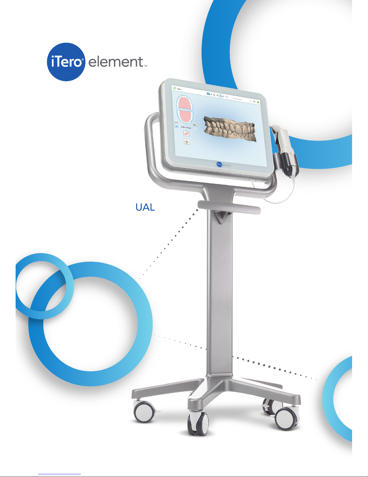
OPERATION MANUAL
Page 2

Page 3

iTero
®
Element
™
Operation Manual
ENGLISH
Publication 109797 Align Technology, Inc. 2017
i
COPYRIGHT
Copyright © by Align Technology Inc. 2017. All rights reserved.
The information contained in this manual is subject to change without notice.
The hardware and software described in this manual are supplied under a Sales and Services Agreement
and may be used only in accordance with the terms of that agreement.
No part of this manual may be reproduced, photocopied, stored in a retrieval system, or transmitted in any
manner (electronic or mechanical) for any purpose other than the customer’s normal usage, without the prior
written permission of Align Technology Inc.
This manual describes the iTero® Element™ Optical Impression Device.
English language version. Updated December 2017.
TRADEMARKS
The following are trademarks and/or service marks of Align Technology, Inc. or one of its subsidiaries or
afliated companies and may be registered in the U.S. and/or other countries: Align Technology Inc., iTero
®
Any other trademarks or registered trademarks appearing in this manual are the property of their respective
owners.
CUSTOMER SUPPORT
Tel: +1 (800) 577-8767
E-mail:
[email protected]
E-mail:
[email protected]
EUROPEAN AUTHORIZED REPRESENTATIVE
Obelis s.a.
Boulevard Général Wahis 53
B - 1030 Brussels, Belgium
www.obelis.net
Tel: +32.2.732.59.54
Fax: +322.732.60.03
E-mail: [email protected]
USA OFFICE
Corporate Headquarters
Align Technology, Inc.
2820 Orchard Parkway
San Jose, California 95134
www.aligntech.com
Tel: +1 (408) 470-1000
Fax: +1 (408) 470-1010
Align Technology Ltd.
3 Ariel Sharon Boulevard
Or-Yehuda 6037606
Israel
Tel: +972 (3) 634-1441
Fax: +972 (3) 634-1440
NETHERLANDS OFFICE
International Headquarters
Align Technology B.V.
Arlandaweg 161
1043 HS Amsterdam
Tel: +31 (0) 20-586-3600
Fax: +31 (0) 20-586-3751
Page 4
iTero
®
Element
™
Operation Manual
ENGLISH
2017 Align Technology, Inc. Publication 109797
ii
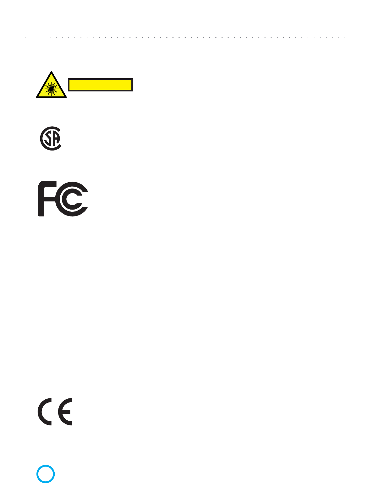
CLASS 1 LASER COMPLIANCE
This device complies with: “21 CFR 1040.10” and “EN 60825-1”.
CSA COMPLIANCE
This device complies with the following CSA standard for Canada and the USA:
“UL Std No. 60601-1 Second Edition – Medical Electrical Equipment Part 1:
General Requirements for Safety”
FCC COMPLIANCE
This device complies with Part 15 of FCC Rules and its operation is subject to the
following two conditions:
1) This device may not cause harmful interference.
2) This device must accept any interference received, Including interference that
may cause undesired operation.
FCC Warning
Modications to the device that are not expressly approved by the manufacturer may void your
authority to operate the device under FCC Rules.
EMC COMPLIANCE
This device complies with the following EMC standard:
“IEC 60601-1-2 Medical electrical equipment - Part 1-2: General requirements for basic safety and essential
performance - Collateral standard: Electromagnetic phenomena - Requirements and tests”.
SAFETY COMPLIANCE
This device complies with the following safety standard:
“IEC 60601-1 Medical electrical equipment –Part 1: General requirements for basic safety and essential
performance.
CE COMPLIANCE
This device complies with Council Directive 93/42/EEC for Medical Devices.
Class 1 Laser Product
C US
Page 5
Manuel d’utilisation iTero
®
Element
™
FRANÇAIS
Publication 109797 Align Technology, Inc. 2017
iii
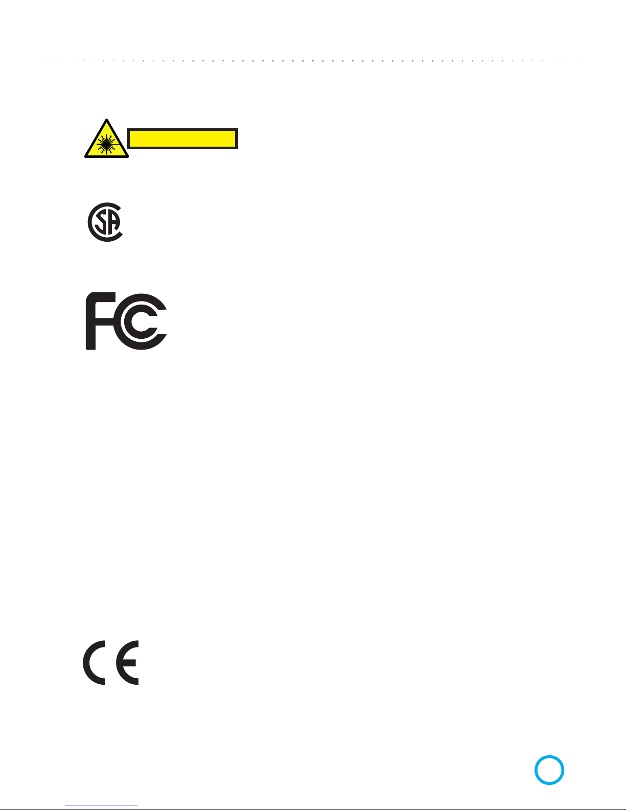
CONFORMITÉ DU LASER CLASSE 1
Cet appareil est conforme aux normes: “21 CFR 1040.10” et “EN 60825-1”.
CONFORMITÉ CSA
Ce dispositif est conforme à la norme CSA pour le Canada et les Ètats-Unis « UL Std
No. 60601-1 Second Edition – Medical Electrical Equipment Part 1: General Requirements for Safety »
CONFORMITÉ FCC
Ce dispositif est conforme à l’Article 15 des Réglementations FCC et son fonctionnement est soumis aux conditions suivantes :
1) Ce dispositif ne doit pas causer d’interférences nuisibles.
2) Ce dispositif doit accepter toute interférence reçue, y compris des interférences
pouvant causer un dysfonctionnement.
Avertissement FCC
Toute modication apportée au dispositif n’ayant pas été expressément approuvée par le fabricant peut annuler
votre droit à utiliser ce dispositif d’après les Réglementations FCC.
CONFORMITÉ CEM
Cet appareil est conforme aux normes de sécurité CEM suivantes :
“IEC 60601-1-2 Dispositifs électromédicaux - Partie 1-2 : Exigences générales pour la sécurité de base et les
performances essentielles - Norme collatérale : Phénomènes électromagnétiques - Prescriptions et essais”
SÉCURITÉ DU DISPOSITIF
Cet appareil est conforme aux normes de sécurité suivantes :
“IEC 60601-1 Dispositifs électromédicaux – Article 1 : Exigences générales pour la sécurité de baseet les performances essentielles”.
CONFORMITÉ CE
Ce dispositif est conforme à la directive 93/42/CEE relative aux dispositifs médicaux.
Produit Laser de Classe 1
C US
Page 6
iTero
®
Element
™
Operation Manual
ENGLISH
2017 Align Technology, Inc. Publication 109797
iv
SYMBOLS
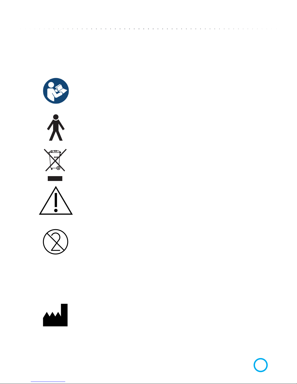
The following symbols may appear on iTero Element hardware components, and may also appear within this
manual and other iTero Element literature.
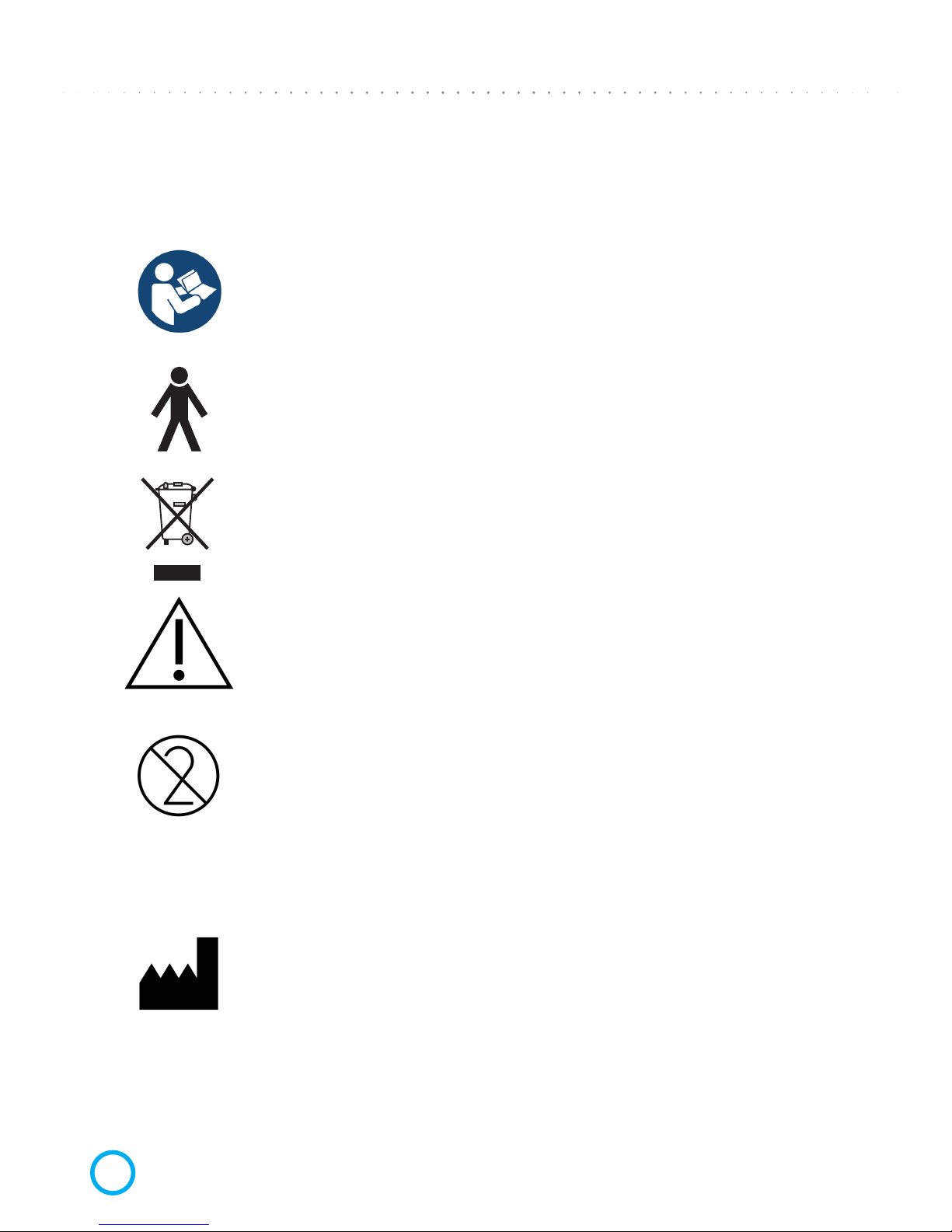
Wherever this symbol appears on the device, it is recommended to refer to this manual
for information on proper usage of the device.
Applied part type B. Any component on which this symbol appears is electric isolation
type B.
Separate collection of electrical waste and electronic equipment is required.
Attention: This symbol is used to highlight the fact that there are specic warnings
or precautions associated with the device. Wherever this symbol appears on the device,
it is mandatory to refer to safety-related information within this manual.
Parts or accessories on which this symbol occurs should not be reused.
CAUTION: US Federal Law restricts this device to sale by or on the order of a licensed
Dentist, Orthodontist or Dental Professional. The system serves as a prescription medical device and should be operated by qualied health-care providers only.
Medical device manufacturer.
"Rx only"
Page 7
Manuel d’utilisation iTero
®
Element
™
FRANÇAIS
Publication 109797 Align Technology, Inc. 2017
v
SYMBOLES
Les symboles suivants peuvent apparaître sur des composants matériels de l’iTero Element tout comme dans ce
manuel et d’autres publications relatives à l’iTero Element.
Lorsque ce symbole apparaît sur le dispositif, il est recommandé de vous reporter à ce
manuel pour des informations sur l’utilisation appropriée de ce dispositif.
Pièce appliquée de type B. Tout composant sur lequel ce symbole apparaît est une
isolation électrique de type B.
Il est nécessaire de collecter séparément les déchets d’équipements électriques et électroniques.
Attention : Ce symbole est utilisé pour souligner le fait qu’il existe des avertissements
ou précautions spéciques associés à ce dispositif. Lorsque ce symbole apparaît sur
le dispositif, il est obligatoire de vous reporter aux informations concernant la sécurité
dans ce manuel.
Les pièces ou accessoires sur lesquels ce symbole apparaît ne doivent pas être réutilisés.
ATTENTION : La Loi fédérale des États-Unis restreint la vente de ce dispositif par ou
pour le compte d’un dentiste, d’un orthodontiste ou d’un professionnel dentaire agréé.
Le système sert de dispositif de prescription médicale et devrait être utilisé uniquement
par des prestataires de soins de santé qualiés.
Fabricant du dispositif médical
"Rx only"
Page 8

iTero
®
Element
™
Operation Manual
ENGLISH
2017 Align Technology, Inc. Publication 109797
vi
SAFETY INSTRUCTIONS
Before beginning to work with the system, all users are required to read these safety instructions.
Power Supply • Power is supplied to the system via an internal medical grade power supply.
Electric • Electric shock hazard!! Only authorized Align Technology technicians can remove
Warning external panels and covers. There are no user-serviceable parts inside.
• To avoid risk of electric shock, iTero Element must only be connected to a supply
mains with protective grounding.
• Only Align Technology approved Web Camera or DOK should be connected to
the USB socket on the back side of the System.
Wireless LAN • The system comes equipped with a Wireless LAN unit.
Safety • Type of protection against electrical shock: Class 1.
Classications • Degree of protection against electrical shock: Type B.
• Degree of protection against harmful ingress of water: Ordinary.
• Equipment not suitable for use in presence of ammable anesthetic mixtures.
• Mode of operation: Continuous.
Prescription • The system serves as a prescription medical device and should be operated by
Health Device qualied health-care providers only.
Scanner • The scanner emits red laser light (680nm Class 1) as well as white LED emissions. Normal
Warnings usage of the scanner does not present any danger to the human eye. However, doctors
should refrain from shining the scanner directly into the patient’s eyes.
• Avoid twisting cable, knotting cable, pulling on cable, stepping on cable.
• When the system is not in use, the scanning unit should be placed inside the holder with
the probe facing to the rear side of the touchscreen so there will be no eye contact with
the laser beam in any case.
Cleaning & • To avoid cross contamination, it is mandatory that after each patient session the
Disinfection disposable plastic sleeve be replaced and the scanning unit be disinfected.
• Dispose of scanner sleeves according to standard operating procedures or local
regulations for the disposal of contaminated medical waste.
Unpacking & • The system should be unpacked and installed following Align Technology’s instructions.
Installing
Work • The system should be moved between rooms with utmost care to avoid damage.
Environment • Do not block the air vents on the Scanning Unit and Base Unit.
• System is intended for indoor use only. It should not be exposed to direct sunlight,
excessive heat or humidity.
Electro • WARNING: This device has been tested and found to comply with the requirements for
Magnetic medical devices according to standard EN60601-1-2. This standard is designed to
Interference provide reasonable protection against harmful interference in a typical medical
installation. However, because of the proliferation of radio-frequency transmitting
equipment and other sources of electrical noise in the healthcare environments
(e.g., cellular phones, mobile two-way radios, electrical appliances), it is possible that
high levels of such interference due to close proximity or strength of source, may result
in disruption of performance of this device.
General • WARNING: No modication of this equipment is allowed.
• WARNING: The touchscreen always needs to be in a stand while in operation!
Page 9

Manuel d’utilisation iTero
®
Element
™
FRANÇAIS
Publication 109797 Align Technology, Inc. 2017
vii
CONSIGNES DE SÉCURITÉ
Avant de commencer à travailler avec le système, tous les utilisateurs doivent lire les consignes de sécurité.
Alimentation • L’alimentation électrique est fournie au système via une alimentation interne pour le milieu
médical.
Avertissement • Danger d’électrocution !! Seuls les techniciens Align autorisés peuvent retirer les
électrique panneaux et couvercles externes. Il ne contient aucune pièce réparable par l’utilisateur.
• An d’éviter les risques d’électrocution, l’ iTero® Element™ doit uniquement être connecté
au secteur par une mise à la terre de protection.
• Uniquement la webcam (approuvée par Align Technology) ou des clés USB peuvent être
connectées au port USB à l’arrière du dispositif.
Réseau Local • L’appareil est livré équipé d’une unité locale sans l.
Sans Fil
Classications • Type de protection contre l’électrocution : Classe 1.
de Sécurité • Degré de protection contre l’électrocution : Type B.
• Degré de protection contre la pénétration d’eau nuisible : Normal.
• Dispositif ne convenant pas à une utilisation en présence de mélanges d’anesthésiques
inammables.
• Mode de fonctionnement : Continu.
Dispositif de • Le système sert de dispositif de prescription médicale et devrait être utilisé uniquement
Prescription par des prestataires de soins de santé qualiés.
Médicale
Avertissements • Le scanner émet une lumière laser rouge (680 nm Classe 1) ainsi que de la lumière blanche
concernant via des DEL. Une utilisation normale du scanner ne présente aucun danger pour l’œil
le scanner humain. Cependant, les praticiens devraient s’abstenir d’éclairer les yeux du patient
directement avec le scanner.
• Évitez de tordre le câble, de faire des nœuds, de tirer dessus ou bien de marcher dessus.
• Lorsque le système n’est pas utilisé, l’unité de balayage devrait être placée dans le support
prévu à cet effet avec la sonde tournée du côté de la face arrière du moniteur an d’éviter
tout contact entre le faisceau laser et les yeux.
Nettoyage et • Pour éviter toute contamination croisée, il est obligatoire de remplacer le manchon jetable
Désinfection en plastique après chaque session avec un patient et de désinfecter l’unité de balayage.
• Jetez les manchons en plastique du scanner selon les procédures normalisées ou les
réglementations locales concernant les déchets médicaux contaminés.
Déballage et • Le dispositif devrait être déballé et installé selon les instructions d’Align.
Installation
Environnement • Le dispositif doit être déplacé d’une pièce à l’autre avec la plus grande précaution an
de Travail d’éviter de l’endommageren faisant preuve du plus grand soin.
• Ne bloquez pas les ouvertures d’aération sur les unités de balayage et de base.
• Le système est destiné à être utilisé en intérieur uniquement. Il ne doit pas être exposé
directement à la lumière du soleil, ni à une chaleur excessive ou à l’humidité.
Interférence • AVERTISSEMENT : Ce dispositif a été testé et est conforme aux exigences concernant les
dispositifs médicaux d’après la norme EN60601-1-2. Cette norme est destinée à apporter
une protection raisonnable contre des interférences nuisibles dans une installation médicale
typique. Cependant, en raison de la prolifération d’équipements transmettant des rdio fréquences et d’autres sources de bruit électrique dans les environnements liés à la santé
(téléphones portables, radios mobiles bidirectionnelles, appareils électriques), il est possible
que des niveaux élevés d’interférences dues à la proximité ou à la puissance de la source
entraînent une perturbation de la performance de ce dispositif.
General • AVERTISSEMENT : Aucune modication de ce dispositif n’est autorisée.
• AVERTISSEMENT : NE PAS UTILISER le moniteur en position horizontale !
Page 10

Page 11

iTero
®
Element
™
Operation Manual
ENGLISH
Publication 109797 Align Technology, Inc. 2017
1
TABLE OF CONTENTS
CHAPTER 1: Introduction . . . . . . . . . . . . . . . . . . . . . . . . . . . . . . . . . . . . . . . . . . . . . . . . . . . . . . 2
About this Operation Manual . . . . . . . . . . . . . . . . . . . . . . . . . . . . . . . . . . . . . . . . . . . . . . . . 2
Intended Use . . . . . . . . . . . . . . . . . . . . . . . . . . . . . . . . . . . . . . . . . . . . . . . . . . . . . . . . . . . . . 2
Benets of the iTero Element System . . . . . . . . . . . . . . . . . . . . . . . . . . . . . . . . . . . . . . . . 2
The iTero Element User Interface . . . . . . . . . . . . . . . . . . . . . . . . . . . . . . . . . . . . . . . . . . . . 3
CHAPTER 2: Basic Hardware Features . . . . . . . . . . . . . . . . . . . . . . . . . . . . . . . . . . 4
Front View of the System . . . . . . . . . . . . . . . . . . . . . . . . . . . . . . . . . . . . . . . . . . . . . . . . . . . . . . 4
Back View of the System . . . . . . . . . . . . . . . . . . . . . . . . . . . . . . . . . . . . . . . . . . . . . . . . 5
Custom Counter Stand . . . . . . . . . . . . . . . . . . . . . . . . . . . . . . . . . . . . . . . . . . . . . . . . . 6
Scanning Unit (Wand) . . . . . . . . . . . . . . . . . . . . . . . . . . . . . . . . . . . . . . . . . . . . . . . . . . . . . . . 7
CHAPTER 3: Operating Instructions . . . . . . . . . . . . . . . . . . . . . . . . . . . . . . . . . . . . . . 8
Initial Power-Up and Boot . . . . . . . . . . . . . . . . . . . . . . . . . . . . . . . . . . . . . . . . . . . . . . . 8
End-of-Day Shut Down . . . . . . . . . . . . . . . . . . . . . . . . . . . . . . . . . . . . . . . . . . . . . . . . . 8
Moving System within the Ofce . . . . . . . . . . . . . . . . . . . . . . . . . . . . . . . . . . . . . . . . . . . . . 8
CHAPTER 4: AC Power Problems—Troubleshooting . . . . . . . . . . . . . . . . . . . . . . . . . 9
Checking & Replacing Main Fuses . . . . . . . . . . . . . . . . . . . . . . . . . . . . . . . . . . . . . . . . . . . . 9
CHAPTER 5: Scanner Handling, Cleaning, and Disinfection Instructions . . . . . . . . . . . . 10
Handling of the Scanning Unit (Wand) . . . . . . . . . . . . . . . . . . . . . . . . . . . . . . . . . . . . . . . . . . . 10
Handling of the Scanning Unit Cable . . . . . . . . . . . . . . . . . . . . . . . . . . . . . . . . . . . . . . . . . . . . 10
Recommended Best Practices for Cleaning and Disinfecting . . . . . . . . . . . . . . . . . . . . . . . . . 10
Cleaning and Disinfectant Materials for Scanning Unit and Base Unit . . . . . . . . . . . . . . . . . 11
CHAPTER 6: Changing Sleeves between Patients . . . . . . . . . . . . . . . . . . . . . . . . . . .12
Cleaning and Disinfecting the Scanning Unit (Wand) . . . . . . . . . . . . . . . . . . . . . . . . . . .12
Replacing Disposable Sleeves . . . . . . . . . . . . . . . . . . . . . . . . . . . . . . . . . . . . . . . . . . . 12
Scanner Sleeves . . . . . . . . . . . . . . . . . . . . . . . . . . . . . . . . . . . . . . . . . . . . . . . . . . . . . . . 13
APPENDIX A: EMC Declaration . . . . . . . . . . . . . . . . . . . . . . . . . . . . . . . . . . . . . . . . . . . . . . . 14
APPENDIX B: Hardware Specications . . . . . . . . . . . . . . . . . . . . . . . . . . . . . . . . . . . . . . . . . . 17
Page 12

iTero
®
Element
™
Operation Manual
ENGLISH
2017 Align Technology, Inc. Publication 109797
2
CHAPTER 1:
Introduction
About this Operation Manual
The iTero Element system is delivered as a proprietary, PC-based workstation for performing
intra oral scans in the doctor’s ofce. This Operation Manual describes how to boot and shut
down the system, how to correctly handle the Scanning Unit/Wand and cable, and how to
clean the Scanning Unit and replace its sleeves between patients.
Intended Use
iTero Element is an optical impression system (CAD/CAM) used to record the topographical
images of teeth and oral tissue. Data generated from iTero may be used in conjunction with
the production of dental devices (e.g., aligners, braces, appliances, etc.) and accessories.
iTero Element software is used with the iTero Element scanner in capturing 3D digital
impressions of teeth, oral soft tissue and structures, and bite relationship. The software
controls the processing of the data, facilitating the integration of data, and exporting of the
data for CAD/CAM fabrication of dental restorations, Orthodontic devices, abutments, and
accessories. In addition to scan data, various patient and case information can be imported/
exported or used for simulation purposes. Other functions are available for verication and
service of the system and to serve as an order management tool.
Benets of the iTero Element System
The iTero Element system provides important advantages over existing crown-production
methods, Including powder-free scanning, greater crown-production accuracy, and
immediate feedback during the scanning process.
Refer to our website http://www.itero.com to learn how the iTero Service can enhance your
business by Increasing patient satisfaction, improving clinical outcomes, and enhancing ofce
efciency.
Page 13
iTero
®
Element
™
Operation Manual
ENGLISH
Publication 109797 Align Technology, Inc. 2017
3
The iTero Element User Interface
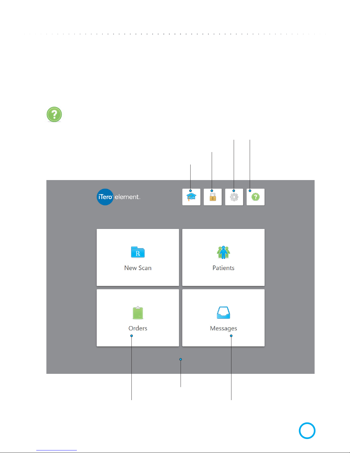
The iTero Element system provides an intuitive user interface for performing digital scans
for Restorative or Orthodontic use. The doctor is guided through the scanning sequence by
means of visual and text assistance. The touchscreen and wand buttons are used to respond
to screen instructions during the scanning process.
One tap on the question mark will enable a transparent Help overlay that will provide
a brief overview. Please note that the Headset image appears instead of the question
mark while in this view. Tap anywhere to close the help screen and return to the
relevant screen.
Tap to enter the Learning Center or start training
Tap anywhere on screen
to close this help overlay
(Tap to start a new case) (Tap to see/search patient list)
Tap to lock the desktop
Tap to set your preferences Double tap to connect
to a support agent for
remote troubleshooting
(please call support rst)
Tap to view notications,
updates and other messages
from Align Technology
Tap to check the
status of your orders
Page 14
iTero
®
Element
™
Operation Manual
ENGLISH
2017 Align Technology, Inc. Publication 109797
4
CHAPTER 2:
Basic Hardware Features
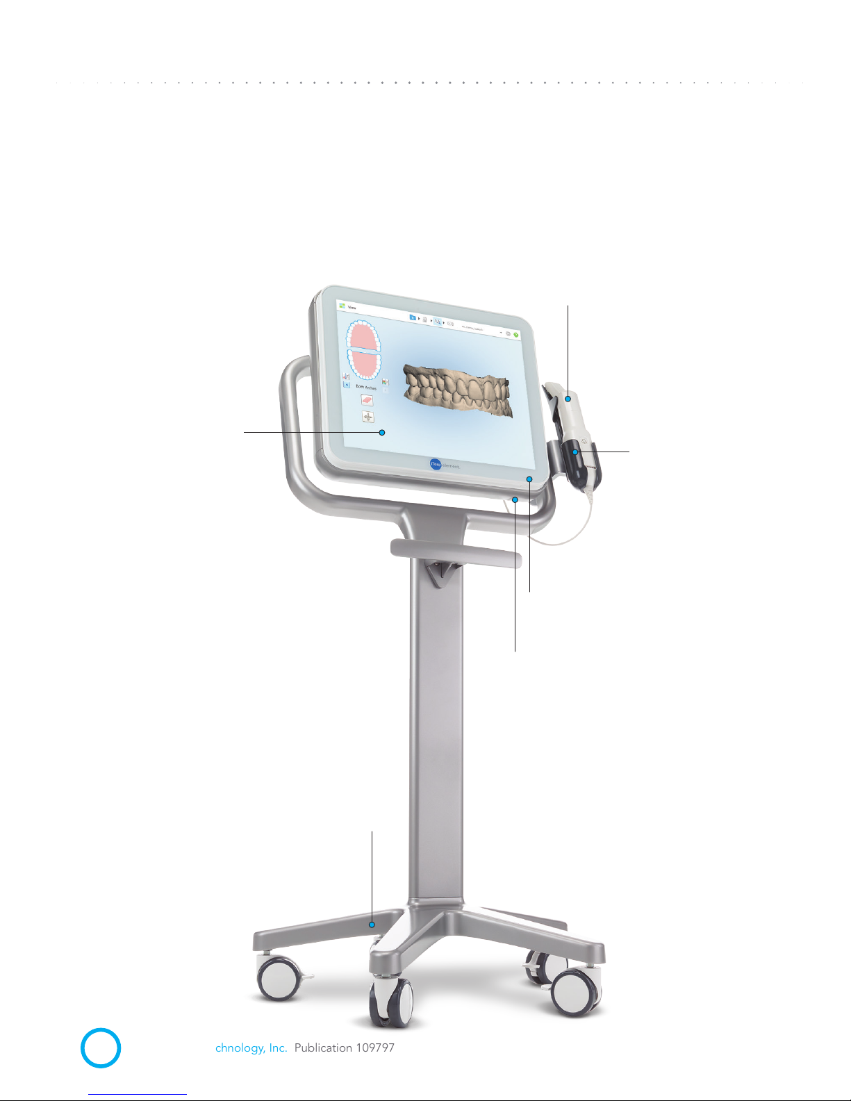
CUSTOM WHEEL STAND HARDWARE FEATURES: Front View of the System
Wheel Base
Scanning Unit (Wand)
Scanning Unit
(Cradle)
Power LED
Power Switch
Touch screen
Page 15
iTero
®
Element
™
Operation Manual
ENGLISH
Publication 109797 Align Technology, Inc. 2017
5
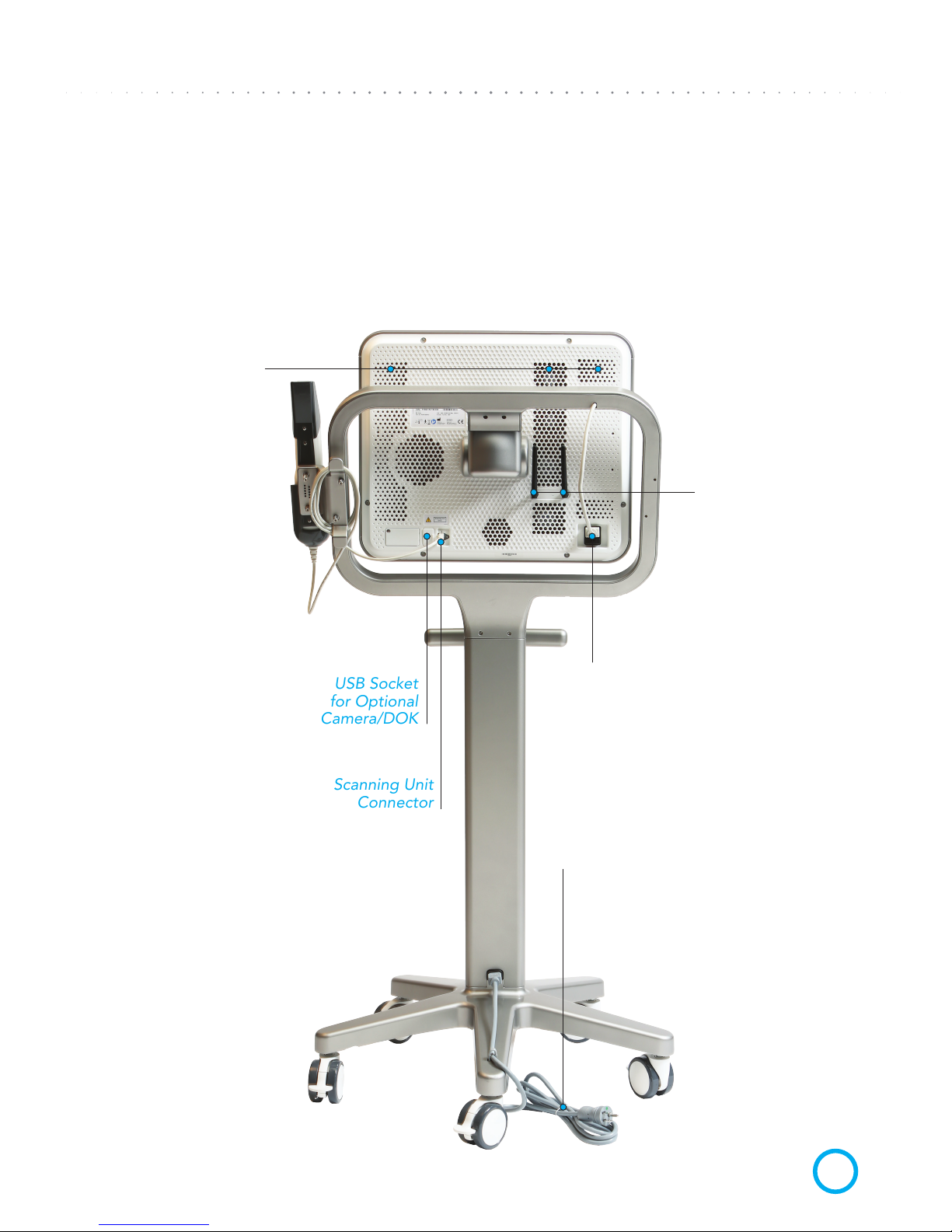
USB Socket
for Optional
Camera/DOK
Scanning Unit
Connector
CUSTOM WHEEL STAND HARDWARE FEATURES: Back View of the System
Air Vents
(Do not block
back of system)
Power Inlet
and Fuse Holder
Wi-Fi Antennas
Power Cord
Page 16
iTero
®
Element
™
Operation Manual
ENGLISH
2017 Align Technology, Inc. Publication 109797
6
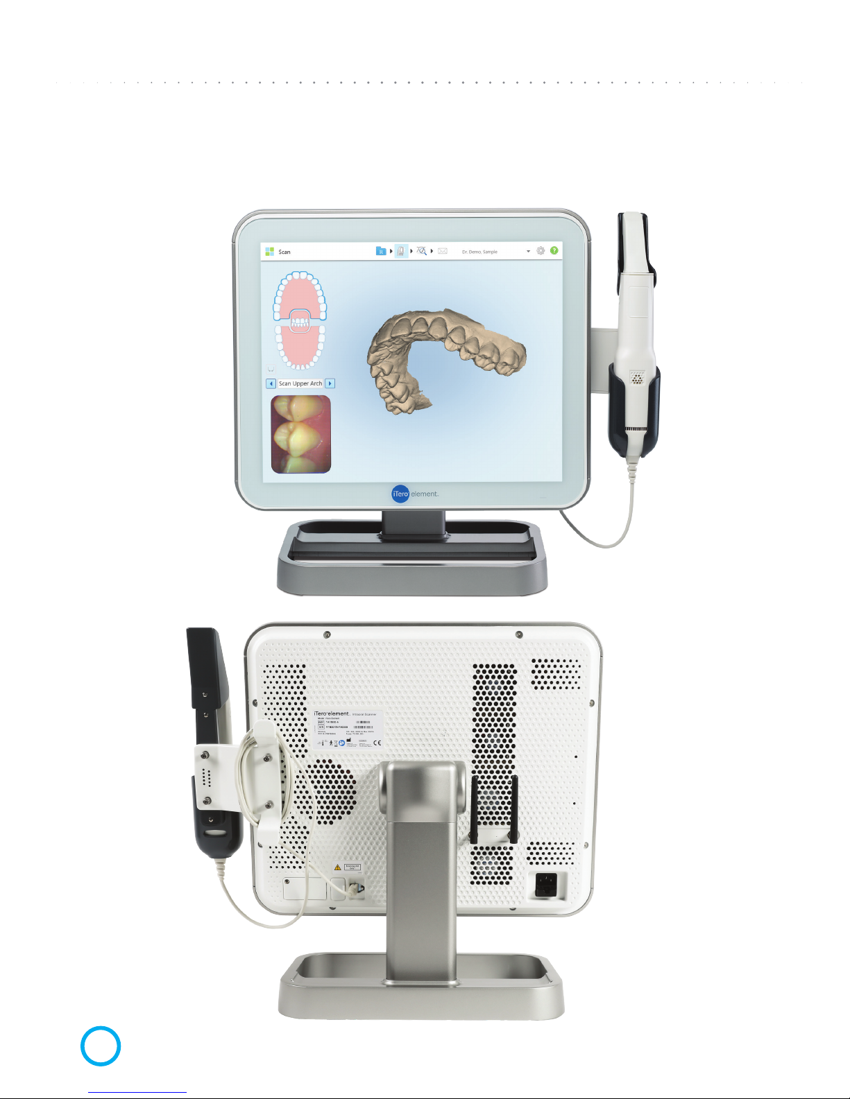
CUSTOM COUNTER STAND: Front and Back View of the System
Page 17
iTero
®
Element
™
Operation Manual
ENGLISH
Publication 109797 Align Technology, Inc. 2017
7
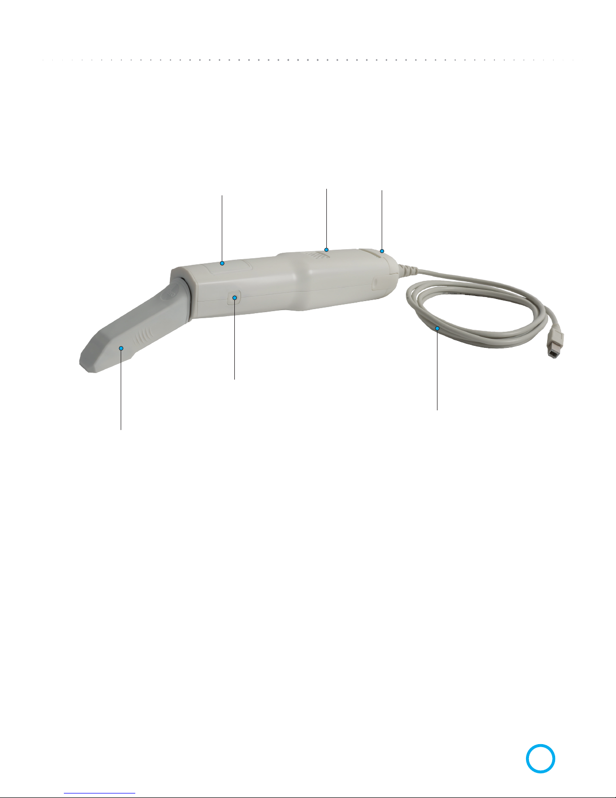
SCANNING UNIT (WAND)
Touchpad
Disposable Sleeve
Detachable Scanning
Unit Cable with USB
connector
Side Buttons:
Scan, On/Off,
Touchpad Activation...
Air Vents
Page 18
iTero
®
Element
™
Operation Manual
ENGLISH
2017 Align Technology, Inc. Publication 109797
8
CHAPTER 3:
Operating Instructions
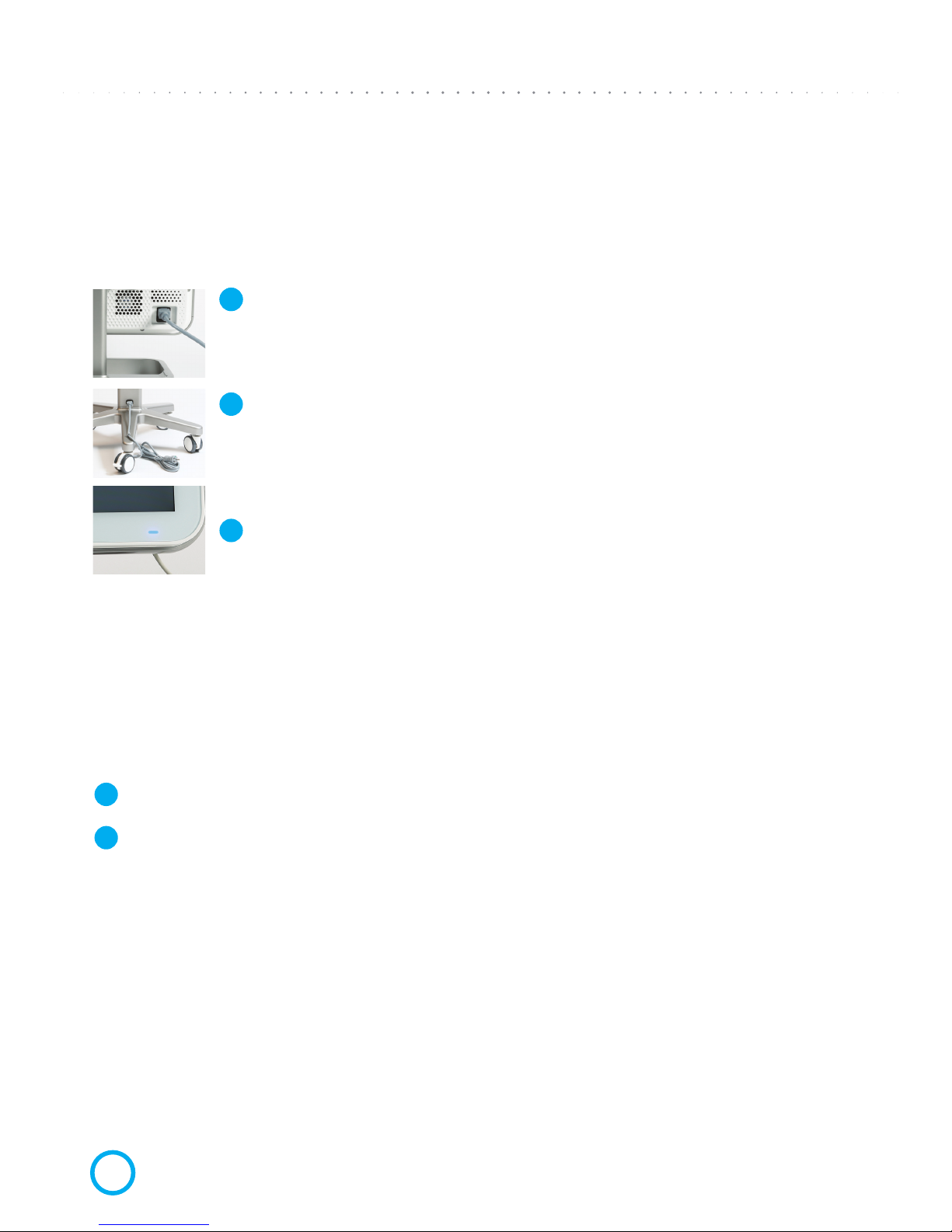
INITIAL POWER-UP AND BOOT
Plug main cable into the Base Unit socket and other end into wall outlet;
Plug free end of Wheel Stand main cable into wall socket.
Press and release the power switch on the bottom of the screen frame, on
the right side. The power LED will turn on.
It is recommended to keep the system in operation during ofce hours to allow background
le transfers between the doctor’s ofce, the doctor’s partnered labs, and the Align
Technology Center. It is recommended to shut down the system at the end of the day,
and to reboot in the morning.
END-OF-DAY SHUT DOWN
Close all les and applications.
Press and release the Power Switch on the bottom of the screen to shut down the system.
MOVING SYSTEM WITHIN THE OFFICE
To ensure maximum system protection, it is recommended to have two people move
the system. Follow these instructions for relocating the system:
1 Verify the Scanning Unit (Wand) sits well inside the Scanning Unit Cradle (holder).
2 Press and release the Power Switch on the bottom of the screen to shut down the system.
3 Unplug system from the wall outlet.
4 Move the system carefully using two people.
5 Place the system at its new location and it plug into a wall outlet.
6 Press and release the power switch to power ON the system.
1
11
2
3
2
Page 19
iTero
®
Element
™
Operation Manual
ENGLISH
Publication 109797 Align Technology, Inc. 2017
9
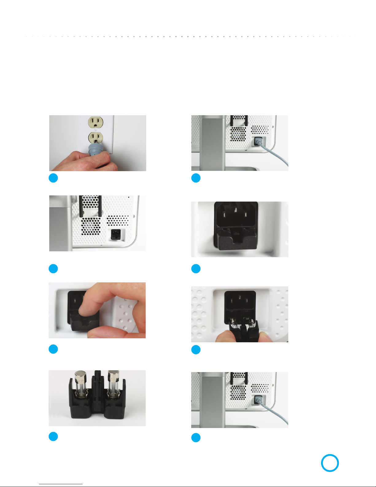
System Access
Move system away from any wall to allow easy access
to the power cord and fuse tray.
View Fuse Tray
The fuse tray is located below the power socket.
Remove & Check Fuses
Carefully remove each fuse from the tray.
Check fuses visually (and with tester if available).
Close Fuse Tray
Close the fuse tray and insert cord rmly.
CHAPTER 4:
AC Power Problems–Troubleshooting
CHECKING & REPLACING MAIN FUSES
Unplug Cord from Wall
Unplug the power cord from the wall socket.
Disconnect Cord from Base Unit
Unplug the power cord from the back of the system.
Open Fuse Tray
Push down on the small plastic part on the fuse
tray to release it, then pull the fuse tray out.
Replace Fuse
If either fuse is blown or suspect, replace both fuses
(See “Fuse Type” specs at the end of the manual.)
1
3
5
7
2
4
6
8
Page 20

iTero
®
Element
™
Operation Manual
ENGLISH
2017 Align Technology, Inc. Publication 109797
10
CHAPTER 5:
Scanner Handling, Cleaning, and
Disinfection Instructions
HANDLING OF THE SCANNING UNIT (WAND)
• The Scanning Unit contains delicate components and should be handled with care.
HANDLING OF THE SCANNING UNIT CABLE
• The scanner cable should be treated with care to avoid possible damage.
• Avoid twisting, knotting, pulling or stepping on cable, etc.
• Between patient sessions, it is recommended to undo any twists and knots in order to
relieve all tension from the scanner cable
RECOMENDED BEST PRACTICES FOR CLEANING AND DISINFECTING
the Scanning Unit, Base Unit, Wheel Stand and/or Counter Stand in between patients.
• Do not spray disinfectant directly on scanner system surfaces.
• Spray the disinfectant on a towel, or use disinfectant wipes for the Scanning Unit,
and Base Unit.
• Warning: over saturation of disinfectant product on the scanner system surfaces may
cause damage, including internal components.
• Follow the disinfectant manufacturers’ instructions for appropriate contact time.
Remove residual liquid disinfectant with a lint-free, clean cloth.
• Note: follow standard precautions for personal protection, as appropriate.
• Warning: DO NOT touch the optical surface of the Scanning Unit (Wand).
Page 21
iTero
®
Element
™
Operation Manual
ENGLISH
Publication 109797 Align Technology, Inc. 2017
11
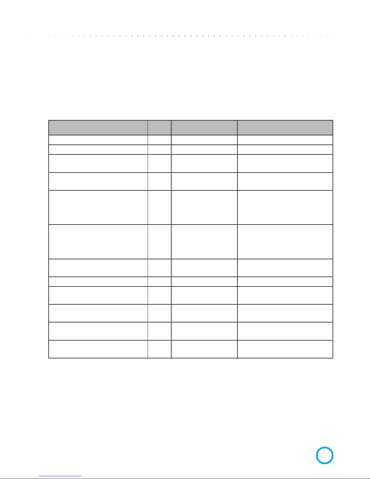
CLEANING AND DISINFECTANT MATERIALS for Scanning Unit and Base Unit
The following cleaning and disinfectant materials are recommended for use for the Scanning
Unit and the Base Unit.
Description pH Manufacturer P/N Manufacturer
Birex® Quat Disinfectant Wipes 7.6 BI 240 Biotrol Intl.
CaviCide AF 12.7 13-800 Metrex
CaviCide
CaviWipe
12.5
13-1000
13-1100
Metrex
CaviCide 1
CaviWipe 1
12.5
13-5000
13-5100
Metrex
Clorox Healthcare
®
Hydrogen Peroxide
Cleaner Disinfecting
Liquid
2-3 30828, 30829 Clorox® Healthcare
™
Clorox Healthcare
®
Hydrogen Peroxide
Cleaner Disinfectant
Wipes
2-3 30824, 30825 Clorox® Healthcare
™
Opti-Cide 3
®
Liquid 7.6
DOCS12-024,
DOCP04-128
Biotrol Intl.
Opti-Cide 3® Wipes 7.6 DOCW06-100 Biotrol Intl.
OPTIM 33TB Liquid
2.5-
3.5
OPT33-1GAL,
OPT-33-1QT
SciCan Inc.
OPTIM 33TB Wipes
2.5-
3.5
OPT33-W10X10,
OPT-33-W12
SciCan Inc.
ProSpray
ProSpray wipes
10
PSC240
PSW-1
Certol
Webcol® Alcohol Prep
Pads
7 5110 Medtronic
Page 22
iTero
®
Element
™
Operation Manual
ENGLISH
2017 Align Technology, Inc. Publication 109797
12
CHAPTER 6:
Changing Sleeves between Patients
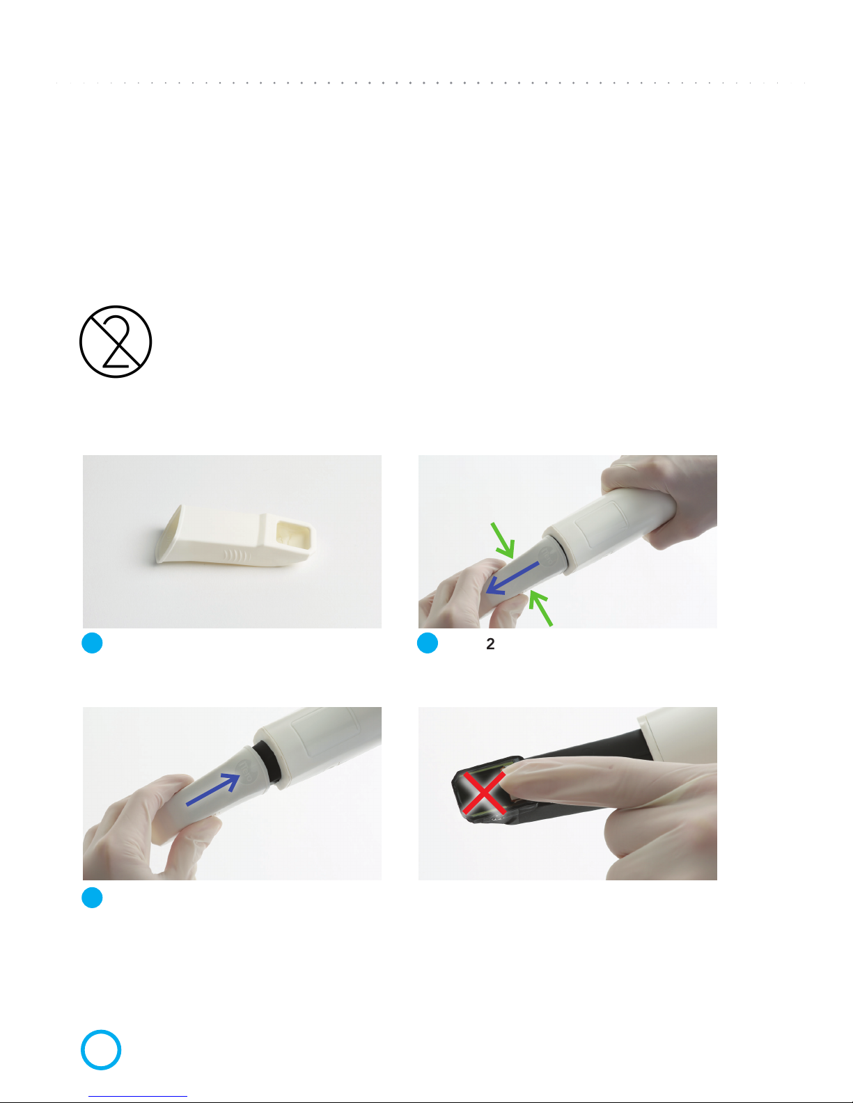
CLEANING AND DISINFECTING THE SCANNING UNIT (WAND)
To avoid cross contamination, it is essential that after each patient you fully clean and disinfect
the Scanning Unit and the disposable sleeve. First spray disinfectant material on towel or use
disinfectant wipes to clean the Scanning Unit and Scanning Unit Cradle (holder). Then proceed
with the steps below to remove the used sleeve and attach a new disposable sleeve.
CAUTION: Dispose of scanner sleeves according to standard operating
procedures or local regulations for the disposal of contaminated medical waste.
REPLACING DISPOSABLE SLEEVES
Step1
When pulling a sleeve OFF or ON, hold the center
of the sleeve.
Step3
Gently slide on new sleeve onto Scanning Unit until
it clicks into place.
Step 2
Press slightly on both sides of the disposable sleeve,
pull the sleeve slowly off the Scanning Unit and discard.
WARNING: OPTICAL SURFACE!
DO NOT touch the optical surface. Contact may
cause damage. If cleaning is necessary, use the
wipes and anti-static cloth found inside the sleeves box.
For proper use, refer to the directions found in the scanner sleeves box.
1
3
2
Page 23
iTero
®
Element
™
Operation Manual
ENGLISH
Publication 109797 Align Technology, Inc. 2017
13
SCANNER SLEEVES
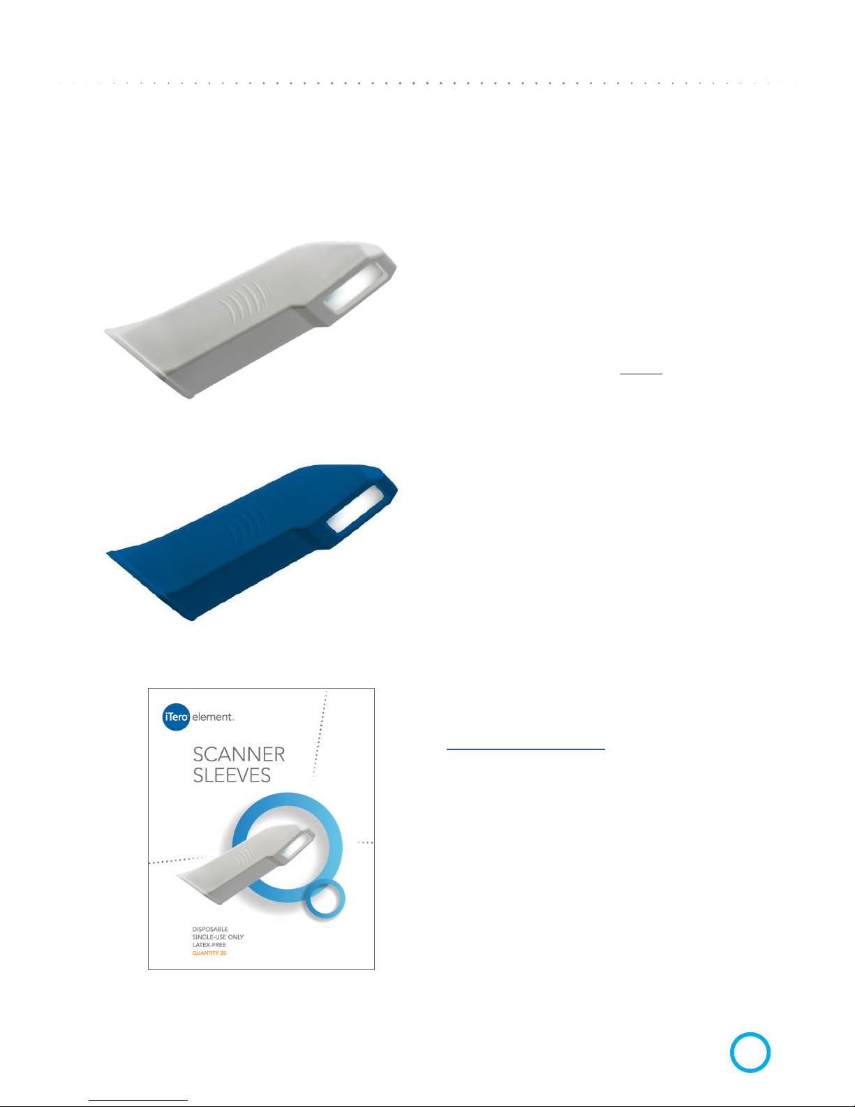
There are two types of sleeves intended for use with the Scanner Unit (Wand):
DISPOSABLE SLEEVE
The white sleeve is a single use Sleeve
for patient scanning. Always replace the white
sleeve on the Scanning Unit between patients
to avoid cross contamination. Please dispose
of the white sleeve after every patient.
PROTECTIVE SLEEVE
The blue Protective Sleeve is used to protect
the optical surface lens when the Scanning
Unit is not in use. Please keep the blue sleeve
in a safe place so that it does not get lost or
damaged.
Scanner Sleeves may be ordered online
in boxes of 25 from the iTero store.
www.store.itero.com
Page 24
iTero
®
Element
™
Operation Manual
ENGLISH
2017 Align Technology, Inc. Publication 109797
14
APPENDIX A:
EMC Declaration
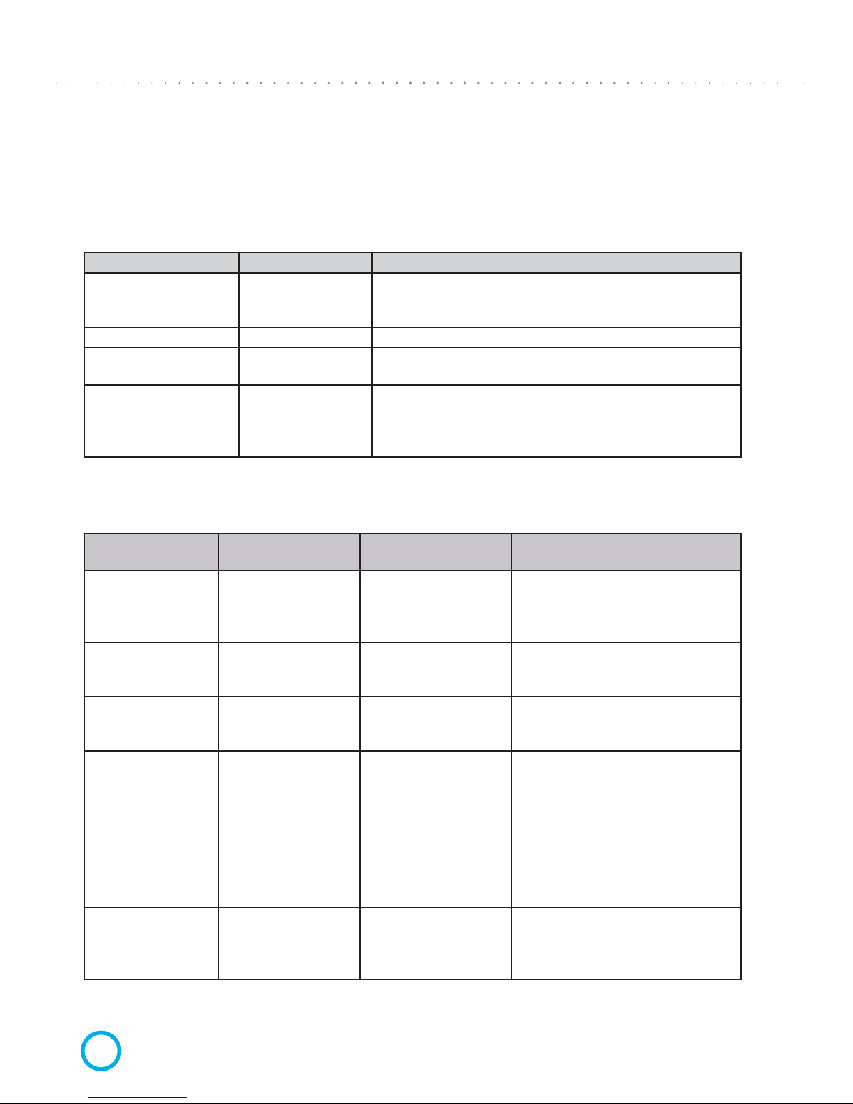
Guidance and Align Technology‘s Declaration – Electromagnetic Emissions – for iTero Element
iTero Element is intended for use in the electromagnetic environment specied below.
The customer or the user of iTero Element should assure that it is used in such an environment.
Emissions Test Compliance Electromagnetic Environment – Guidance
RF emissions CISPR 11 Group 1
iTero Element uses RF energy only for its internal function.
Therefore, its RF emissions are very low and are not likely to
cause any interference in nearby electronic equipment.
RF emissions CISPR 11 Class B
Harmonic emissions IEC
61000-3-2
Complies, class A
Voltage uctuations/
icker emissions IEC
61000-3-3
Complies
iTero Element is suitable for use in all establisments, Includ-
ing domestic establishments and those directly connected to
the public low-voltage power supply network that supplies
buildings used for domestic purposes.
Guidance and Align Technology’s Declaration – Electromagnetic Immunity – for iTero Element
iTero Element is intended for use in the electromagnetic environment specied below.
The customer or the user of iTero Element should assure that it is used in such an environment.
Immunity Test IEC 60601 Test Level Compliance Level
Electromagnetic Environment –
Guidance
Electrostatic discharge (ESD) IEC
61000-4-2
± 6 kV contact ± 8
kV air
± 6 kV contact ± 8 kV
air
Floors should be wood, concrete
or ceramic tile. If oors are covered
with synthetic material, the relative
humidity should be at least 30%.
Electrical fast transient/burst IEC
61000-4-4
± 2 kV for power
supply lines ± 1 kV for
input/output lines
± 2 kV for power supply
lines NA
Mains power quality should be that
of a typical commercial or hospital
environment.
Surge IEC 610004-5
± 1 kV line(s) to line(s)
± 2 kV line(s) to earth
± 1 kV line(s) to line(s) ±
2 kV line(s) to earth
Mains power quality should be that
of a typical commercial or hospital
environment.
Voltage dips, short
interruptions and
voltage variations on
power supply input
lines IEC 61000-4-11
<5% UT
(>95% dip in UT) for
0,5 cycle
40% UT (60% dip in
UT) for 5 cycles 70 %
UT (30% dip in UT) for
25 cycles
<5% UT (>95% dip in
UT) for 5 s
<5% UT
(>95% dip in UT) for 0,5
cycle
40% UT (60% dip in UT)
for 5 cycles 70 % UT
(30% dip in UT) for 25
cycles <5% UT (>95%
dip in UT) for 5 s
Mains power quality should be that
of a typical commercial or hospital
environment. If the user of the iTero
Element system requires continued
operation during power mains interruptions, it is recommended that the
iTero Element system be powered
from an uninterruptible power supply
or a battery.
Power frequency
(50/60 Hz) magnetic
eld IEC 61000-4-8
3 A/m 3 A/m
Power frequency magnetic elds
should be at levels characteristic of a
typical location in a typical commercial or hospital environment.
NOTE: UT is the A.C. mains voltage prior to application of the test level.
Page 25
iTero
®
Element
™
Operation Manual
ENGLISH
Publication 109797 Align Technology, Inc. 2017
15
Guidance and Align Technology’s Declaration – Electromagnetic Immunity – for iTero Element
that is not Life-Supporting
The iTero Element is intended for use in the electromagnetic environment specied below.
The customer or the user of the iTero Element should assure that it is used in such an environment.
Immunity Test IEC 60601
Test Level
Compliance
Level
Electromagnetic Environment – Guidance
Conducted RF
IEC 61000-4-6
Radiated RF
IEC 61000-4-3
3 Vrms
150 kHz to 80
MHz
3 V/m
80 MHz to
2.5 GHz
3 Vrms
150 kHz to 80
MHz
3 V/m
80 MHz to 2.5
GHz
Portable and mobile RF communications equipment should be used no closer to any part of the
iTero
Element system, Including cables, than the recommended separation distance calculated from the
equation applicable to the frequency of the transmitter.
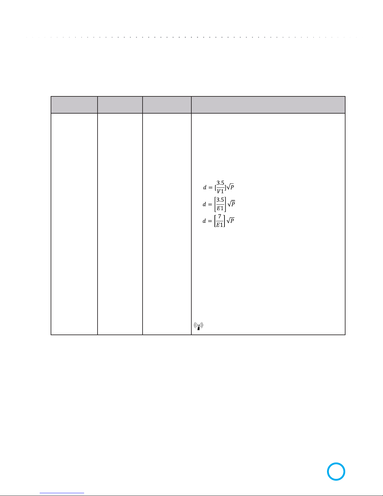
Recommended separation distance:
where P is the maximum output power rating of the
transmitter in watts (W) according to the transmitter
manufacturer and d is the recommended separation distance in metres (m).
Field strengths from xed RF transmitters, as determined by an electromagnetic site survey, should
be less than the compliance level in each frequency
range.
Interference may occur in the vicinity of equipment
marked with the following symbol:
NOTE 1: At 80 MHz and 800 MHz, the higher frequency range applies.
NOTE 2: These guidelines may not apply in all situations. Electromagnetic propagation is affected by absorption
and reection from structures, objects and people.
Field strengths from xed transmitters, such as base stations for radio (cellular/cordless) telephones and land
mobile radios, amateur radio, AM and FM radio broadcast and TV broadcast cannot be predicted theoretically
with accuracy. To assess the electromagnetic environment due to xed RF transmitters, an electromagnetic site
survey should be considered. If the measured eld strength in the location in which the iTero Element system
is used exceeds the applicable RF compliance level above, the iTero Element system should be observed to
verify normal operation. If abnormal performance is observed, additional measures may be necessary, such
as re-orienting or relocating the iTero Element system. Over the frequency range 150 kHz to 80 MHz, eld
strengths should be less than 3 V/m.
150 kHz to 80 MHz
80 MHz to 800 MHz
800 MHz to 2.5 GHz
Page 26
iTero
®
Element
™
Operation Manual
ENGLISH
2017 Align Technology, Inc. Publication 109797
16
Recommended Separation Distances Between Portable and Mobile RF Communications
Equipment and the iTero Element System that is not Life-Supporting
iTero Element is intended for use in the electromagnetic environment in which radiated RF disturbances are
controlled. The customer or the user of the iTero Element can help prevent electromagnetic interference by
maintaining a minimum distance between portable and mobile RF communications equipment (transmitters)
and the iTero Element system as recommended below, according to the maximum output power of the
communications equipment.
Rated maximum
output power of
transmitter W
Separation distance according to frequency of transmitter
m
150 kHz to 80 MHz
0.12
3.8
0.38
12
1.2
0.12
3.8
0.38
12
1.2
0.23
7.3
0.73
23
2.3
0,01
10
0,01
100
1
80 MHz to 800 MHz 800 MHz to 2.5 GHz
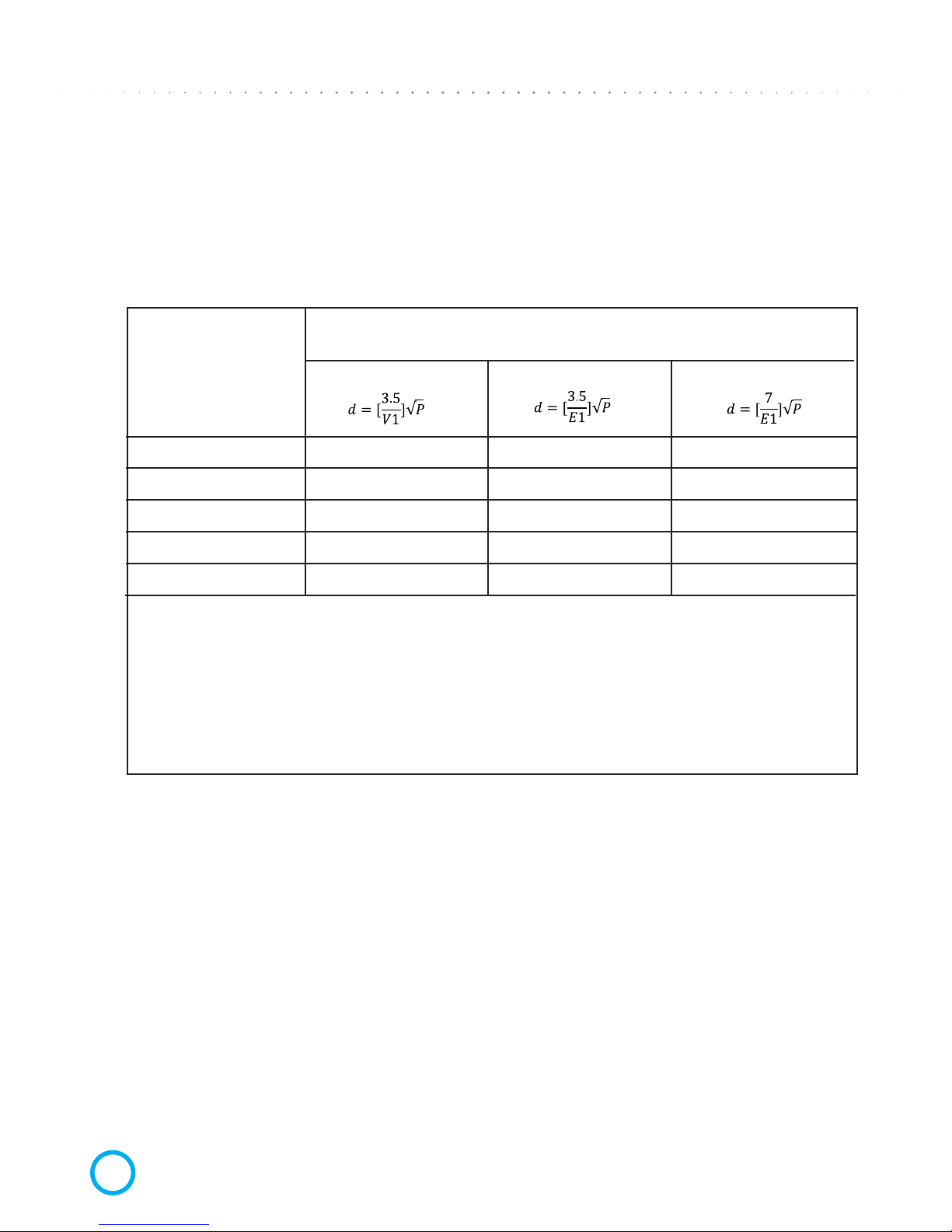
For transmitters rated at a maximum output power not listed above, the recommended separation distance
d in metres (m) can be estimated using the equation applicable to the frequency of the transmitter,
where P is the maximum output power rating of the transmitter in watts (W) according to the transmitter
manufacturer.
NOTE 1: At 80 MHz and 800 MHz, the separation distance for the higher frequency range applies.
NOTE 2: These guidelines may not apply in all situations. Electromagnetic propagation is affected by
absorption and reection from structures, objects and people.
Page 27
iTero
®
Element
™
Operation Manual
ENGLISH
Publication 109797 Align Technology, Inc. 2017
17
APPENDIX B:
Hardware Specications
ITEM DESCRIPTION
Monitor 19” monitor
Scanner
Scanner emits red laser light (680nm Class 1) as well as
white LED emissions.
Wireless LAN
LAN card provides local network communications with
wireless connectivity.
Mains Fuses
T3.15AL (3.15A, slow-blow) 250V glass tube fuses (5 x 20
mm).
Operating Power 100-240VAC- 50/60 Hz – 350VA (max)
Operating Temperature 18°to 26°C / 64.4° to 78.8°F
Storage/Transportation
Temperature
-5°to 50°C 23° to 122°F
Operating Pressure &
Altitude
Pressure: 520 mmHg to 760 mmHg (69.3 kPa to 101.3 kPa)
Altitude: 0 feet to 10,000 feet
Storage/Transportation
Pressure & Altitude
Pressure: 430 mmHg to 760 mmHg (57.3 kPa to 101.3 kPa)
Altitude: 0 feet to 15,000 feet
Relative Humidity Operating: 40% to 70%; Storage: 30% to 90%
Dimensions
Base Unit:
Height: 389 mm (~15 Inches)
Width: 459 mm (~18 Inches)
Depth: 123 mm (~5 Inches
Scanning Unit:
Length: 338.5 mm (~13 Inches)
Width: 53.5 mm (~2 Inches)
Depth: 69.8 mm (~3 Inches)
Net Weight
Base Unit: 11 kg (~24 lbs)
Scanning Unit: 0.47 kg (~1 lbs)
Shipping Weight
~37.5 kg (~83 lbs)
Page 28

CORPORATE HEADQUARTERS
Align Technology, Inc.
2820 Orchard Parkway
San Jose, CA 95134, USA
©2017 Align Technology, Inc.
INTERNATIONAL HEADQUARTERS
Align Technology B.V.
Arlandaweg 161
1043 HS Amsterdam
The Netherlands
 Loading...