

ITEM C 3-Series Product Manual
Product Manual
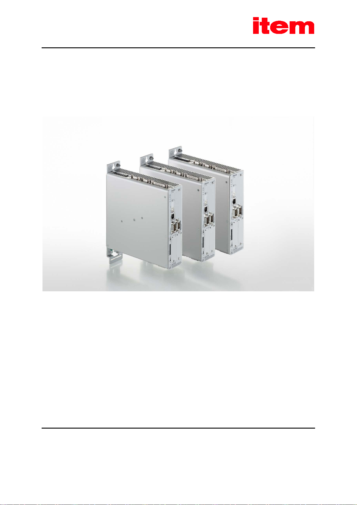
item Servo Positioning Controller C 3-Series
designed for Functional Safety
item Industrietechnik GmbH Telephone: +49-(0)212-6580-0
Friedenstraße 107-109 Fax: +49-(0)212-6580-310
42699 Solingen
Germany
http://www.item24.com
E-mail: info@item24.com

Translation of the original instructions
Copyrights
© 2016 item Industrietechnik GmbH. All rights reserved.
The information and data in this document have been composed to the best of our knowledge. However, deviations between
the document and the product cannot be excluded entirely. For the devices and the corresponding software in the version
handed out to the customer, item guarantees the contractual use in accordance with the user documentation. In the case of
serious deviations from the user documentation, item has the right and the obligation to repair, unless it would involve an
unreasonable effort. A possible liability does not include deficiencies caused by deviations from the operating conditions
intended for the device and described in the user documentation.
item does not guarantee that the products meet the buyer’s demands and purposes or that they work together with other
products selected by the buyer. item does not assume any liability for damages resulting from the combined use of its products
with other products or resulting from improper handling of machines or systems.
item Industrietechnik GmbH reserves the right to modify, amend, or improve the document or the product without prior
notification.
This document may, neither entirely nor in part, be reproduced, translated into any other natural or machine-readable
language nor transferred to electronic, mechanical, optical or any other kind of data media, without the express authorisation
of the author.
Trademarks
Any product names in this document may be registered trademarks. The sole purpose of any trademarks in this document is
the identification of the corresponding products.
item Motion Soft
®
is a registered trademark of item Industrietechnik GmbH.
Page 2

Revision Information
Author: item Industrietechnik GmbH
Manual title:
File name: P-HB_item Steuerung_C3_5p0_EN_bearbeitet.docx
Version 5.0 November 2016
Product Manual „item Servo Positioning Controller C 3-Series“
Page 3

TABLE OF CONTENTS:
1 GENERAL ............................................................................................................. 15
1.1 Documentation .............................................................................................. 15
1.2 Scope of supply ............................................................................................. 16
2 SAFETY NOTES FOR ELECTRICAL DRIVES AND CONTROLLERS ....................................... 17
2.1 Symbols....................................................................................................... 17
2.2 General notes ................................................................................................ 18
2.3 Hazards resulting from misuse........................................................................... 20
2.4 Safety instructions .......................................................................................... 21
2.4.1 General safety instructions ................................................................. 21
2.4.2 Safety notes for assembly and maintenance ........................................... 23
2.4.3 Protection against contact with electrical parts ....................................... 25
2.4.4 Protection against electric shock by way of protective extra-low voltage (PELV)26
2.4.5 Protection against dangerous movements ............................................. 26
2.4.6 Protection against contact with hot parts ............................................... 27
2.4.7 Protection during the handling and installation of the devices ..................... 28
3 PRODUCT DESCRIPTION .......................................................................................... 29
3.1 General ....................................................................................................... 29
3.2 Power supply ................................................................................................ 32
3.2.1 Three-phase AC power supply ............................................................ 32
3.2.1.1 Switch-on behaviour: ....................................................................................32
3.2.2 DC bus circuit linking, DC supply ......................................................... 32
3.2.2.1 DC bus circuit linking ....................................................................................32
3.2.2.2 DC supply ..................................................................................................32
3.2.3 Mains fuse ..................................................................................... 32
3.3 Brake chopper .............................................................................................. 33
3.4 Communication interfaces ................................................................................ 33
3.4.1 Serial interface [X5] ......................................................................... 33
3.4.2 USB interface [X19] ......................................................................... 34
3.4.3 UDP interface [X18] ......................................................................... 34
3.4.4 CAN interface [X4] ........................................................................... 34
Page 4

3.4.5 Technology module: Profibus ............................................................. 35
3.4.6 Technology module: EtherCAT ............................................................ 35
3.4.7 I/O functions and device control .......................................................... 35
4 TECHNICAL DATA .................................................................................................. 36
4.1 General technical data ..................................................................................... 36
4.2 Control elements and display elements ................................................................ 37
4.3 Power supply [X9] .......................................................................................... 38
4.4 Motor connector [X6] ...................................................................................... 39
4.4.1 Current derating .............................................................................. 40
4.5 Angle encoder connector [X2A] and [X2B] ........................................................... 44
4.5.1 Resolver connector [X2A] .................................................................. 45
4.5.2 Encoder connector [X2B] .................................................................. 46
4.6 Communication interfaces ................................................................................ 48
4.6.1 RS232 [X5] ................................................................................... 48
4.6.2 USB [X19] ..................................................................................... 48
4.6.3 Ethernet [X18] ................................................................................ 48
4.6.4 CAN bus [X4] ................................................................................. 48
4.6.5 SD/MMC card ................................................................................ 48
4.6.6 I/O interface [X1] ............................................................................. 49
4.6.7 Incremental encoder input [X10] ......................................................... 50
4.6.8 Incremental encoder output [X11] ....................................................... 51
5 FUNCTION OVERVIEW ............................................................................................. 52
5.1 Motors ........................................................................................................ 52
5.1.1 Synchronous servomotors ................................................................. 52
5.1.2 Linear motors ................................................................................. 52
5.2 Functions of the item Servo Positioning Controller C 3-Series .................................... 53
5.2.1 Compatibility .................................................................................. 53
5.2.2 Pulse width modulation (PWM) ........................................................... 53
5.2.3 Setpoint management ...................................................................... 54
5.2.4 Torque-controlled mode .................................................................... 54
5.2.5 Speed-controlled mode ..................................................................... 55
5.2.6 Torque-limited speed control .............................................................. 55
Page 5

5.2.7 Synchronisation with external clock signals ............................................ 55
5.2.8 Load torque compensation in the case of vertical axes .............................. 55
5.2.9 Positioning and position control .......................................................... 55
5.2.10 Synchronisation, electronic gear unit .................................................... 56
5.2.11 Brake management ......................................................................... 56
5.3 Positioning control .......................................................................................... 57
5.3.1 Overview ....................................................................................... 57
5.3.2 Relative positioning .......................................................................... 58
5.3.3 Absolute positioning ......................................................................... 58
5.3.4 Motion profile generator .................................................................... 58
5.3.5 Homing ......................................................................................... 58
5.3.6 Positioning sequences ...................................................................... 59
5.3.7 Optional stop input ........................................................................... 60
5.3.8 Contouring control with linear interpolation ............................................ 60
5.3.9 Time-synchronised multi-axis positioning ............................................... 61
6 FUNCTIONAL SAFETY TECHNOLOGY .......................................................................... 62
6.1 General ....................................................................................................... 62
6.1.1 DIP switch ..................................................................................... 63
6.1.2 Assignment of the DIP switch ............................................................. 64
6.2 Integrated safety technology (schematic representation) .......................................... 66
6.3 Module variants ............................................................................................. 67
6.3.1 FBA module ................................................................................... 67
6.3.2 FSM 2.0 – STO (Safe Torque Off) ........................................................ 68
7 MECHANICAL INSTALLATION ................................................................................... 69
7.1 Important notes ............................................................................................. 69
7.2 Device view .................................................................................................. 71
7.3 Installation.................................................................................................... 73
8 ELECTRICAL INSTALLATION ..................................................................................... 74
8.1 Connector configuration .................................................................................. 74
8.2 item C 3-Series – complete system ..................................................................... 75
8.3 Connector: power supply [X9] ........................................................................... 77
Page 6

8.3.1 Configuration on the device [X9].......................................................... 77
8.3.2 Mating connector [X9] ...................................................................... 77
8.3.3 Pin assignment [X9] ......................................................................... 78
8.3.4 Cable type and configuration [X9] ........................................................ 78
8.3.5 Connection notes [X9] ...................................................................... 79
8.4 Connector: motor [X6] ..................................................................................... 80
8.4.1 Configuration on the device [X6].......................................................... 80
8.4.2 Mating connector [X6] ...................................................................... 80
8.4.3 Pin assignment [X6] ......................................................................... 80
8.4.4 Cable type and configuration [X6] ........................................................ 81
8.4.5 Connection notes [X6] ...................................................................... 81
8.5 Connector: I/O communication [X1] .................................................................... 83
8.5.1 Configuration on the device [X1].......................................................... 85
8.5.2 Mating connector [X1] ...................................................................... 85
8.5.3 Pin assignment [X1] ......................................................................... 86
8.5.4 Cable type and configuration [X1] ........................................................ 87
8.5.5 Connection notes [X1] ...................................................................... 87
8.6 Connector: resolver [X2A] ................................................................................ 88
8.6.1 Configuration on the device [X2A] ........................................................ 88
8.6.2 Mating connector [X2A] .................................................................... 88
8.6.3 Pin assignment [X2A] ....................................................................... 88
8.6.4 Cable type and configuration [X2A] ...................................................... 89
8.6.5 Connection notes [X2A] .................................................................... 89
8.7 Connector: encoder [X2B] ................................................................................ 90
8.7.1 Configuration on the device [X2B] ........................................................ 90
8.7.2 Mating connector [X2B] .................................................................... 90
8.7.3 Pin assignment [X2B] ....................................................................... 91
8.7.4 Cable type and configuration [X2B] ...................................................... 93
8.7.5 Connection notes [X2B] .................................................................... 94
8.8 Connector: incremental encoder input [X10] ......................................................... 96
8.8.1 Configuration on the device [X10] ........................................................ 96
8.8.2 Mating connector [X10] .................................................................... 96
8.8.3 Pin assignment [X10] ....................................................................... 96
Page 7

8.8.4 Cable type and configuration [X10] ...................................................... 97
8.8.5 Connection notes [X10] .................................................................... 97
8.9 Connector: incremental encoder output [X11] ....................................................... 98
8.9.1 Configuration on the device [X11] ........................................................ 98
8.9.2 Mating connector [X11] .................................................................... 98
8.9.3 Pin assignment [X11] ....................................................................... 98
8.9.4 Cable type and configuration [X11] ...................................................... 99
8.9.5 Connection notes [X11] .................................................................... 99
8.10 Connector: CAN bus [X4] ............................................................................... 100
8.10.1 Configuration on the device [X4]........................................................ 100
8.10.2 Mating connector [X4] .................................................................... 100
8.10.3 Pin assignment [X4] ....................................................................... 100
8.10.4 Cable type and configuration [X4] ...................................................... 101
8.10.5 Connection notes [X4] .................................................................... 101
8.11 Connector: RS232/COM [X5] .......................................................................... 103
8.11.1 Configuration on the device [X5]........................................................ 103
8.11.2 Mating connector [X5] .................................................................... 103
8.11.3 Pin assignment [X5] ....................................................................... 103
8.11.4 Cable type and configuration [X5] ...................................................... 104
8.11.5 Connection notes [X5] .................................................................... 104
8.12 Connector: USB [X19] ................................................................................... 105
8.12.1 Configuration on the device [X19] ...................................................... 105
8.12.2 Mating connector [X19] .................................................................. 105
8.12.3 USB [X19] ................................................................................... 105
8.12.4 Cable type and configuration [X19] .................................................... 105
8.13 SD/MMC card ............................................................................................. 106
8.13.1 Supported card types ..................................................................... 106
8.13.2 Supported functions ....................................................................... 106
8.13.3 Supported file systems ................................................................... 106
8.13.4 File names ................................................................................... 106
8.13.5 Pin assignment SD/MMC card .......................................................... 107
8.13.6 BOOT-DIP switch ........................................................................... 108
8.14 Notes concerning the safe and EMC-compliant installation ...................................... 109
Page 8

8.14.1 Definitions and terms ..................................................................... 109
8.14.2 General information on EMC............................................................. 109
8.14.3 EMC areas: first and second environment ............................................ 109
8.14.4 EMC-compliant cabling ................................................................... 110
8.14.5 Operation with long motor cables ...................................................... 111
8.14.6 ESD protection ............................................................................. 112
9 ADDITIONAL REQUIREMENTS TO BE FULFILLED BY THE SERVO POSITIONING CONTROLLERS
FOR UL APPROVAL ............................................................................................... 113
9.1 Mains fuse .................................................................................................. 113
9.2 Wiring requirements and environmental conditions ............................................... 113
9.3 Motor temperature sensor .............................................................................. 113
10 START-UP ........................................................................................................... 114
10.1 General connection notes ............................................................................... 114
10.2 Tools/material ............................................................................................. 114
10.3 Connecting the motor .................................................................................... 114
10.4 Connecting the item Servo Positioning Controller C 3-Series to the power supply ......... 115
10.5 Connecting the PC (serial interface) .................................................................. 115
10.6 Connecting the PC (USB interface, alternative) ..................................................... 115
10.7 Operability check ......................................................................................... 115
11 SERVICE FUNCTIONS AND ERROR MESSAGES ........................................................... 116
11.1 Protection and service functions ...................................................................... 116
11.1.1 Overview ..................................................................................... 116
11.1.2 Phase and mains power failure detection ............................................. 116
11.1.3 Overcurrent and short-circuit monitoring ............................................. 117
11.1.4 Overvoltage monitoring of the DC bus circuit ........................................ 117
11.1.5 Temperature monitoring of the heat sink ............................................. 117
11.1.6 Monitoring of the motor .................................................................. 117
11.1.7 I²t monitoring ............................................................................... 117
11.1.8 Power monitoring of the brake chopper .............................................. 118
11.1.9 Start-up status .............................................................................. 118
11.1.10 Rapid discharge of the DC bus circuit ................................................. 118
Page 9

11.1.11 Operating hours counter ................................................................. 118
11.2 Operating mode and error messages ................................................................ 119
11.2.1 Operating mode and error indication .................................................. 119
11.2.2 Error messages ............................................................................ 120
12 TECHNOLOGY MODULES ....................................................................................... 153
12.1 PROFIBUS-DP interface ................................................................................. 153
12.1.1 Product description ........................................................................ 153
12.1.2 Technical data .............................................................................. 153
12.1.3 Pin assignment and cable specifications.............................................. 155
12.1.3.1 Pin assignment .........................................................................................155
12.1.3.2 Mating connector ......................................................................................155
12.1.3.3 Cable type and configuration ........................................................................155
12.1.4 Termination and bus terminating resistors ........................................... 156
12.2 EtherCAT ................................................................................................... 157
12.2.1 Product description ........................................................................ 157
12.2.2 Characteristics of the EtherCAT technology module ............................... 157
12.2.3 Technical data .............................................................................. 158
12.2.4 Display elements ........................................................................... 158
12.2.5 EtherCAT interface ........................................................................ 159
12.3 General installation notes for technology modules ................................................ 160
Page 10

TABLE OF FIGURES:
Figure 1:
Figure 2: Control structure of the item C 3-Series ...................................................................................53
Figure 3: Motion profiles of the item Servo Positioning Controller C 3-Series .................................................58
Figure 4: Path program ....................................................................................................................59
Figure 5: Linear interpolation between two data values ............................................................................60
Figure 6: Schematic representation of the integrated safety technology .......................................................66
Figure 7: FBA module: front view ........................................................................................................67
Figure 8: item Servo Positioning Controller C 3-Series: installation space .....................................................70
Figure 9: item Servo Positioning Controller C 3-10: front view ....................................................................71
Figure 10: item Servo Positioning Controller C 3-05: view from above ...........................................................72
Figure 11: item Servo Positioning Controller C 3-05: view from below ...........................................................72
Figure 12: item Servo Positioning Controller C 3-Series: mounting plate ........................................................73
Figure 13: Connection to the power supply and motor ...............................................................................74
Figure 14: Complete set-up of the item C 3-Series with a motor and PC .........................................................76
Type key ..........................................................................................................................29
Figure 15: Power supply [X9] ..............................................................................................................79
Figure 16: Motor connector [X6] ..........................................................................................................81
Figure 17: Connecting a holding brake with a high current demand (> 2 A) to the device ...................................82
Figure 18: Basic circuit diagram of connector [X1] ...................................................................................84
Figure 19: Pin assignment: resolver connector [X2A] ................................................................................89
Figure 20: Pin assignment: analogue incremental encoder – option [X2B] .....................................................94
Figure 21: Pin assignment: incremental encoder with a serial interface (e.g. EnDat, HIPERFACE) – option [X2B] .....94
Figure 22: Pin assignment: digital incremental encoder - option [X2B] ...........................................................95
Figure 23: Pin assignment [X10]: incremental encoder input ......................................................................97
Figure 24: Pin assignment [X11]: incremental encoder output.....................................................................99
Figure 25: CAN bus cabling example ...................................................................................................101
Figure 26: Integrated CAN terminating resistor ......................................................................................102
Figure 27: Pin assignment RS232 null modem cable [X5] ........................................................................104
Figure 28: Pin assignment USB interface [X19], front view .......................................................................105
Figure 29: Pin assignment: SD/MMC card ............................................................................................107
Figure 30: PROFIBUS-DP interface: front view .......................................................................................154
Figure 31: PROFIBUS-DP interface: connection with external terminating resistors .........................................156
Figure 32: EtherCAT module: front view ...............................................................................................158
Page 11

Figure 33: Servo positioning controller with an integrated technology module ...............................................160
Page 12

Table of Tables:
Table 1:
Scope of supply .................................................................................................................16
Table 2: Connector set: POWER connector ..........................................................................................16
Table 3: Connector set: DSUB connector .............................................................................................16
Table 4: Connector set: shield connector .............................................................................................16
Table 5: Technical data: ambient conditions and qualification ...................................................................36
Table 6: Technical data: dimensions and weight....................................................................................36
Table 7: Technical data: cable specifications ........................................................................................37
Table 8: Technical data: motor temperature monitoring system ................................................................37
Table 9: Display elements and RESET button .......................................................................................37
Table 10: Technical data: power data [X9] .............................................................................................38
Table 11: Technical data: internal braking resistor [X9] ............................................................................38
Table 12: Technical data: external braking resistor [X9] ............................................................................38
Table 13: Technical data: motor connector [X6] ......................................................................................39
Table 14: Controller C 3-05: rated current values for a blocked or slow-running motor (fel) ≤ 5Hz and for an ambient
temperature ≤ 40°C ............................................................................................................40
Table 15: Controller C 3-05: rated current values for a rotating motor (fel) ≥ 20 Hz and for an ambient temperature ≤
40°C ...............................................................................................................................40
Table 16: Controller C 3-10: rated current values for a blocked or slow-running motor (fel) ≤ 5 Hz and for an ambient
temperature ≤ 40°C ............................................................................................................42
Table 17: Controller C 3-10: rated current values for a rotating motor (fel) ≥ 20 Hz and for an ambient temperature ≤
40°C ...............................................................................................................................43
Table 18: Technical data: resolver [X2A] ...............................................................................................45
Table 19: Technical data: resolver interface [X2A] ...................................................................................45
Table 20: Technical data: encoder evaluation [X2B] .................................................................................46
Table 21: Technical data: RS232 [X5] ..................................................................................................48
Table 22: Technical data: USB [X19] ....................................................................................................48
Table 23: Technical data: Ethernet [X18] ..............................................................................................48
Table 24: Technical data: CAN bus [X4] ................................................................................................48
Table 25: Technical data: SD/MMC card ...............................................................................................48
Table 26: Technical data: digital inputs and outputs [X1] ...........................................................................49
Table 27: Technical data: analogue inputs and outputs [X1] ......................................................................50
Table 28: Technical data: incremental encoder input [X10] .......................................................................50
Table 29: Technical data: incremental encoder output [X11] .....................................................................51
Page 13

Table 30: Output voltage at the motor terminals in the case of a DC bus circuit voltage (U
) of 560 V .................53
ZK
Table 31: Overview of the DIP switch functionality ...................................................................................63
Table 32: Fieldbus-specific assignment of the DIP switches .......................................................................65
Table 33: Pin assignment [X9] ............................................................................................................78
Table 34: Pin-and-socket connector [X9]: external braking resistor ..............................................................79
Table 35: Pin assignment [X6] ............................................................................................................80
Table 36: Pin assignment: I/O communication [X1]..................................................................................86
Table 37: Pin assignment [X2A] ..........................................................................................................88
Table 38: Pin assignment: analogue incremental encoder – option [X2B] .....................................................91
Table 39: Pin assignment: incremental encoder with a serial interface (e.g. EnDat, HIPERFACE) – option [X2B] .....92
Table 40: Pin assignment: digital incremental encoder – option [X2B] .........................................................93
Table 41: Pin assignment [X10]: incremental encoder input ......................................................................96
Table 42: Pin assignment [X11]: incremental encoder output.....................................................................98
Table 43: Pin assignment CAN bus [X4] ..............................................................................................100
Table 44: Pin assignment RS232 interface [X5] ....................................................................................103
Table 45: Pin assignment USB interface [X19] .....................................................................................105
Table 46: Pin assignment: SD card ....................................................................................................107
Table 47: Pin assignment: MMC card .................................................................................................107
Table 48: EMC requirements: first and second environment ....................................................................110
Table 49: Operating mode and error indication .....................................................................................119
Table 50: Error messages ................................................................................................................121
Table 51: Technical data: PROFIBUS-DP interface: ambient conditions, dimensions, and weight ......................153
Table 52: Technical data: PROFIBUS-DP interface: interfaces and communication ........................................154
Table 53: Pin assignment: PROFIBUS-DP interface ................................................................................155
Table 54: Technical data: EtherCAT module: ambient conditions, dimensions, and weight ..............................158
Table 55: Display elements ..............................................................................................................158
Table 56: Signal level and differential voltage .......................................................................................159
Page 14

General
1 General
1.1 Documentation
The purpose of this product manual is to ensure the safe use of the item Servo Positioning Controller C 3-Series. It contains
safety notes, which must be complied with.
Further information can be found in the following manuals of the item C Series product range:
Product Manual "item servo positioning controller C 1-Series": Description of the technical data and device functionality
plus notes concerning the installation and operation of
Product Manual "FSM 2.0 - STO": Description of the technical data and device functionality plus notes on the
installation and operation of the FSM 2.0 – STO.
PROFIBUS Manual "item Servo Positioning Controller C Series": Description of the implemented PROFIBUS-DP
protocol.
CANopen Manual "item Servo Positioning Controller C Series": Description of the implemented CANopen protocol as
per DSP402.
C 1-02, C 1-05, and C 1-08.
EtherCAT Manual "item Servo Positioning Controller C Series": Description of the implemented EtherCAT protocol
(CoE) (German version).
You can find all of these documents on our homepage for download (http://www.item24.com).
Certificates and declarations of conformity for the products described in this manual can be found at http://www.item24.com.
The entire software functionality of the new item C Serie will be implemented in the course of a step-by-step development
process.
This version of the product manual contains the functions of the firmware version 4.1.7001.1.1.
Page 15
General
Connector set: POWER connector
Connector set: DSUB connector
Connector set: shield connector
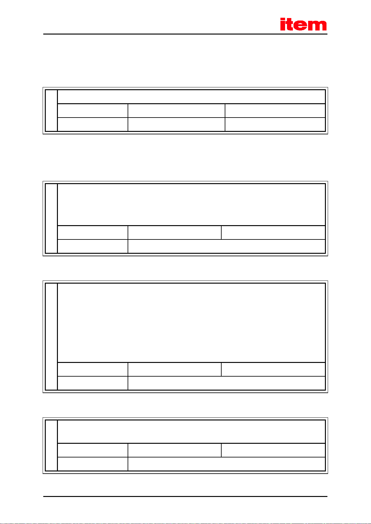
1.2 Scope of supply
The scope of supply includes:
Table 1: Scope of supply
1x
item Servo Positioning Controller C 3-Series
Type Controller C 3-05 Controller C 3-10
item order number 0.0.668.65 0.0.668.66
Mating connectors for power, control, or shaft encoder connections are not part of the standard scope of supply. However,
they can be ordered as accessories.
Table 2: Connector set: POWER connector
1x
This connector set includes the mating connectors for the following connections:
- Power supply [X9]
- Motor connection [X6]
Type
item order number
Controller C 3-05 Controller C 3-10
auf Anfrage erhältlich
Table 3: Connector set: DSUB connector
1x
This connector set includes the mating connectors for the following connections:
- I/O interface [X1]
- Angle encoder connection [X2A]
- Angle encoder connection [X2B]
- CAN fieldbus interface [X4]
- Incremental encoder input [X10]
- Incremental encoder output [X11]
Type
Controller C 3-05 Controller C 3-10
item order number
Table 4: Connector set: shield connector
1x
This connector set includes two shield terminals (SK14)
Type
item order number 0.0.668.19
auf Anfrage erhältlich
Controller C 3-05 Controller C 3-10
Page 16
Safety notes for electrical drives and controllers
DANGER!
damage to property
personal injuries
Caution! Hazardous voltage.
2 Safety notes for electrical drives and
controllers
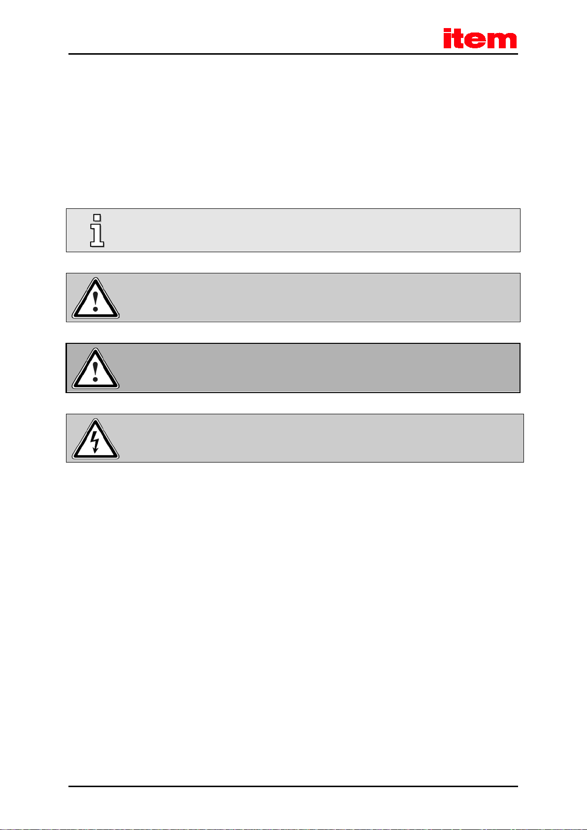
2.1 Symbols
Information
Important information and notes.
Caution!
Non-compliance may result in severe damage to property.
Non-compliance may result in
This safety note indicates a potential, hazardous voltage.
and
.
Page 17

Safety notes for electrical drives and controllers
2.2 General notes
In case of damage resulting from non-compliance with the safety notes in this manual, item Industrietechnik GmbH will not
assume any liability.
Prior to commissioning the system, read the
and
If the documentation in the language at hand is not understood accurately, please contact and inform your supplier.
The correct and safe operation of the servo positioning controller requires the proper and professional transport, storage,
mechanical installation, and project planning – with a consideration of the risks as well as of the protective and emergency
measures – plus the proper and professional electrical installation, operation, and maintenance of the devices.
Only trained and qualified personnel are authorised to work with or on the electrical devices and systems:
TRAINED AND QUALIFIED PERSONNEL
in the sense of this product manual or in the sense of the safety notes on the product itself are persons who are sufficiently
familiar with the project, set-up, installation, commissioning, and operation of the product as well as with all of the warnings
and precautions as per the instructions in this manual and who are sufficiently qualified in their field of expertise:
They have been trained, instructed, and authorised to perform the switching and earthing (grounding) of the
devices/systems in line with the applicable safety standards and to label them accordingly as per the job requirements.
They have been trained and instructed in line with the applicable safety standards in terms of the maintenance and use of
adequate safety equipment.
chapter 8.14 (Notes concerning the safe and EMC-compliant installation
Safety notes for electrical drives and controllers
, page 109).
as of page 17
They have completed first aid training.
The following instructions must be read thoroughly prior to the initial operation of the system in order to prevent personal
injuries and/or damage to property:
These safety instructions must be complied with at all times.
Do not attempt to install or start the servo positioning controller without having read all of the safety
instructions in this document concerning the electrical drives and controllers. These safety instructions and all
other user notes must be read prior to performing any work with the servo positioning controller.
In case you do not have any user notes for the servo positioning controller, please contact your sales
representative. Immediately demand these documents to be sent to the person responsible for the safe
operation of the servo positioning controller.
If the servo positioning controller is sold, rented out, or otherwise distributed to third parties, these safety
instructions must be included.
Page 18

Safety notes for electrical drives and controllers
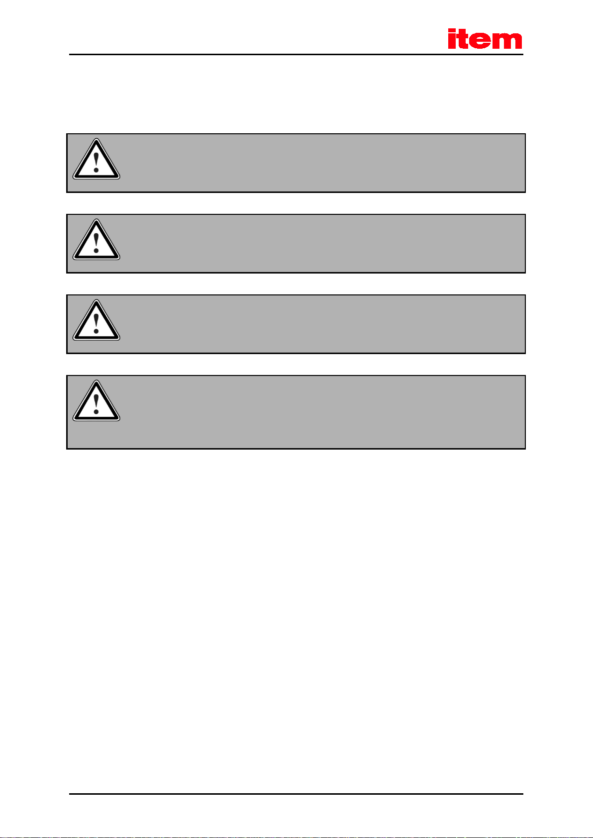
DANGER!
Improper handling of the servo positioning controller and non-compliance with the warnings as well as
improper manipulation of the safety devices may result in damage to property, personal injuries, electric
shock or, in extreme cases, in death.
Opening the servo positioning controller by the operator is not permissible for safety and warranty reasons.
Professional project planning is a prerequisite for the correct and trouble-free operation of the servo
positioning controller!
Page 19
Safety notes for electrical drives and controllers
DANGER!
DANGER!
DANGER!
DANGER!
Dangerous movements!
2.3 Hazards resulting from misuse
High electrical voltages and high load currents!
Danger to life or risk of serious personal injury from electric shock!
High electrical voltage caused by incorrect connections!
Danger to life or risk of personal injury from electric shock!
The surfaces of the device housing may be hot!
Risk of injury! Risk of burns!
Danger to life, risk of serious personal injury or property damage due to unintentional movements of the
motors!
Page 20
Safety notes for electrical drives and controllers
DANGER!
2.4 Safety instructions
2.4.1 General safety instructions
The servo positioning controller has an IP20 protection rating and a pollution degree rating of 2. Ensure that
the environment corresponds to this protection rating and pollution degree rating.
Only use manufacturer-approved accessories and spare parts.
The servo positioning controllers must be connected to the mains power supply in accordance with the EN
standards so that they can be disconnected from the mains power supply by way of suitable disconnectors
(e.g. main switches, contactors, circuit breakers).
The servo positioning controller can be protected with a 300 mA AC/DC-sensitive residual-current device of
type B.
Gold contacts or contacts with a high contact pressure should be used to switch the control contacts.
For the switchgear, preventive interference suppression measures should be taken, e.g. in the form of RC
circuits or diodes connected to the contactors and relays.
Compliance with the safety rules and regulations of the country in which the device will be operated must be
ensured.
The ambient conditions that are specified in the product documentation must be maintained. Safety-critical
applications are not allowed, unless specifically approved by the manufacturer.
chapter 8.14 Notes concerning the safe and EMC-compliant installation
See
information concerning the EMC-compliant installation. The manufacturer of the machine or system is
responsible for ensuring compliance with the limits that are specified by the applicable national rules and
regulations.
The technical data and the connection and installation conditions for the servo positioning controller are
specified in this product manual. Compliance with these specifications is absolutely essential.
The general set-up and safety rules and regulations concerning the work on power installations (e.g. DIN,
VDE, EN, IEC, or any other national or international rules and regulations) must be complied with.
(page 109) for further
Non-compliance may result in death, personal injury, or significant damage to property.
Page 21

Safety notes for electrical drives and controllers
Without any claim to completeness, the following standards, rules, and regulations apply:
Other standards that are to be complied with by the user:
VDE 0100 Erection of power installations with nominal voltages up to 1000 V
EN 1037 Safety of machinery - Prevention of unexpected start-up
EN 60204-1
EN 61800-3 Adjustable speed electrical power drive systems - Part 3: EMC requirements and specific test
EN 61800-5-1 Adjustable speed electrical power drive systems - Part 5-1: Safety requirements - Electrical,
EN 61800-5-2
EN ISO 12100
EN ISO 13849-1 Safety of machinery - Safety-related parts of control systems - Part 1: General principles for
EN ISO 13849-2
EN 574 Safety of machinery - Two-hand control devices
EN 1088
Safety of machinery - Electrical equipment of machines - Part 1: General requirements
methods
thermal and energy
Adjustable speed electrical power drive systems - Part 5-2: Safety requirements - Functional
Safety of machinery - General principles for design - Risk assessment and risk reduction
design
Safety of machinery - Safety-related parts of control systems - Part 2: Validation
Safety of machinery - Interlocking devices associated with guards
EN ISO 13850 Safety of machinery - Emergency stop function
Page 22
Safety notes for electrical drives and controllers
of the machine. Deactivated output stages or deactivated controller enable signals are no suitable means of
2.4.2 Safety notes for assembly and maintenance
In terms of the assembly and maintenance of the system, the corresponding DIN, VDE, EN, and IEC regulations as well as all of
the national and local safety regulations and rules for the prevention of accidents apply. The system manufacturer or operator
is responsible for ensuring compliance with these regulations:
Only personnel who have been trained and qualified for working on or with electrical devices are authorised to
operate, maintain, and/or repair the servo positioning controller.
Prevention of accidents, injuries, and/or damage to property:
Vertical axes must be additionally secured against falling down or lowering after the motor has been switched
off, for example by way of the following:
mechanical locking of the vertical axis,
external braking, catching, or clamping devices, or
sufficient weight counterbalance of the axis.
The standard motor holding brake that is included in the scope of supply or any other external motor holding
brake that is actuated by the drive controller is not suitable for the protection of the operators if used alone!
Disconnect the electrical equipment from the power supply by way of the main switch and secure it so that it
cannot be reconnected. Then, wait until the DC bus circuit has discharged prior to any of the following:
maintenance and repairs
cleaning
long downtimes
Prior to performing any maintenance tasks, ensure that the power supply has been turned off and locked and
that the DC bus circuit has been discharged.
The external or internal braking resistor carries dangerous DC bus circuit voltages during the operation of the
servo positioning controller and up to 5 minutes thereafter. Wait until this time is over prior to performing any
work on the affected connections. Measure the voltages for your own protection. Contact with these high DC
bus circuit voltages may result in death or serious personal injury.
Be careful during the assembly. During the assembly and also later on during the operation of the drive,
ensure that no drilling chips, metal dust, or installation parts (screws, nuts, cable sections) can fall into the
into the servo positioning controller.
Ensure also that the external power supply of the controller (24 V) is switched off.
The DC bus circuit or the mains voltage must always be switched off prior to switching off the 24 V controller
supply.
Ensure that the AC or DC power supplies are switched off and locked prior to performing any work in the area
Page 23

Safety notes for electrical drives and controllers
locking. In the case of a malfunction, the drive may accidentally be put into action.
This does not apply to drives with the "Safe Stop" safety feature in accordance with EN 954-1 CAT 3 or with
the "Safe Torque Off" safety feature in accordance with EN 61800-5-2. In the item C 3-Series, these safety
features can be realised, for example, by way of an FSM 2.0 - STO module.
Perform the commissioning with idle motors in order to avoid mechanical damage, e.g. due to an incorrect
direction of rotation.
Electronic devices are never fail-safe. It is the user’s responsibility to ensure that the system is brought to a
safe state if the electrical device fails.
The servo positioning controller and, in particular, the braking resistor (either external or internal) can exhibit
high temperatures that may cause serious burns if touched.
Page 24
Safety notes for electrical drives and controllers
DANGER!
2.4.3 Protection against contact with electrical parts
This section solely applies to devices and drive components with voltages above 50 V. Contact with parts carrying voltage of
more than 50 V may be dangerous and cause electric shock. Certain parts will inevitably carry dangerous voltages during the
operation of electrical devices.
High electrical voltage!
Danger to life, risk of electric shock, and risk of serious personal injury!
The applicable DIN, VDE, EN, and IEC regulations as well as all of the national and local safety and accident prevention
regulations apply to the operation of the device/system. The system manufacturer or operator is responsible for ensuring
compliance with these regulations:
Install the respective covers and guards against accidental contact prior to switching the device/system on.
Rack-mounted devices must be protected against accidental contact by way of a housing, e.g. a switch
cabinet. The national accident prevention regulations must be complied with!
Connect the protective earth conductor (ground conductor) of the electrical system securely to the mains
power supply. Due to the integrated line filters, the leakage current exceeds 3.5 mA!
Comply with the minimum copper cross-section for the protective earth conductor (ground conductor) over its
entire length (see EN 60800-5-1, for example).
Prior to start-up and even for brief measurements or tests, connect the protective earth conductor (ground
conductor) of all of the electrical devices in accordance with the circuit diagram or connect it to the earthing
system on site. Otherwise, the housing may carry high voltages which can cause electric shock.
Do not touch the electrical connections of the components when they are switched on.
Prior to accessing electrical parts carrying voltages above 50 V, disconnect the device from the mains power
supply or voltage source. Secure it so that it cannot be switched on.
The magnitude of the DC bus circuit voltage must be taken into consideration during the installation process
in order to ensure proper insulation and protection. Ensure proper earthing (grounding), conductor rating, and
protection against short circuits.
The device includes a rapid discharge circuit for the DC bus circuit in accordance with
device constellations, however, mostly in the case of parallel connection of several servo positioning
controllers in the DC bus circuit or in the case of an unconnected braking resistor, this rapid discharge may be
rendered ineffective. In these cases, the servo positioning controllers may still carry dangerous voltage levels
until up to 5 minutes after they have been switched off (residual capacitor charge).
EN 60204-1. In certain
Page 25
Safety notes for electrical drives and controllers
DANGER!
DANGER!
2.4.4 Protection against electric shock by way of protective extra-low voltage (PELV)
All of the connections and terminals with voltages up to 50 V of the servo positioning controller have protective extra-low
voltage. They are insulated in accordance with the following standards:
International: IEC 60364-4-41
European countries within the EU: EN 61800-5-1
High electrical voltage caused by incorrect connections!
Danger to life and risk of injury due to electric shock!
Only devices, electrical components, and wires or cables with protective extra-low voltage (PELV) may be connected to
connectors and terminals with voltages from 0 to 50 V.
Connect only those voltages and circuits that are securely isolated from any dangerous voltages. This isolation can be realised
by way of isolation transformers, safe optocouplers, or battery operation without mains power.
2.4.5 Protection against dangerous movements
Dangerous movements can be caused by the faulty actuation of the connected motors. Causes may be as follows:
improper or faulty wiring or cabling
errors during the operation of the components
errors of the sensors and transducers
defective or non-EMC-compliant components
software errors in superordinate control system
These errors can occur directly after the activation of the device or after some time during the operation.
The monitoring systems in the drive components exclude any malfunction in the connected drives to the greatest possible
extent. However, in view of the protection of the operators, particularly in terms of the risk of injuries and/or damage to
property, relying solely on this measure is not recommended. Until the built-in monitoring systems become effective, faulty
drive movements should always be anticipated. The extent of these faulty drive movements depends on the type of control and
on the operating state.
Dangerous movements!
Danger to life, risk of injury, serious personal injury, or damage to property!
Page 26
Safety notes for electrical drives and controllers
DANGER!
For the reasons mentioned above, protection must be ensured by monitoring or by superordinate measures. This must be
implemented by the system manufacturer based on the specific system situation and on a hazard and fault analysis. This also
includes the safety rules and regulations that apply to the system. Random movements of the machine or other malfunctions
may be caused by deactivating, bypassing, or failing to activate the safety devices.
2.4.6 Protection against contact with hot parts
The surfaces of the device housing may be hot!
Risk of injury! Risk of burns!
Do not touch the surfaces of the housing in the vicinity of heat sources! Risk of burns!
Before accessing the devices, let them cool for 10 minutes after they have been switched off.
Touching hot parts of the equipment, such as the housing which contains heat sinks and resistors, may cause
burns!
Page 27
Safety notes for electrical drives and controllers
DANGER!
2.4.7 Protection during the handling and installation of the devices
Improper handling and installation of certain parts and components may cause injuries under adverse conditions.
Risk of injury due to improper handling!
Risk of personal injury caused by crushing, shearing, cutting, or impacts!
The following general safety instructions apply:
Comply with the general set-up and safety regulations concerning the handling and installation of the devices.
Use suitable installation and transport devices.
Prevent trapping and crushing by suitable protective measures.
Use suitable tools only. If specified, use special tools.
Use the lifting devices and tools in a proper manner.
If necessary, use suitable protective equipment (e.g. safety goggles, protective footwear, protective gloves).
Stay out from under suspended loads.
Immediately remove any liquid spills on the floor in order to prevent slipping.
Page 28
Product description
3 Product description
3.1 General
The servo positioning controllers of the item servo positioning controller C Series are intelligent AC servo inverters with
extensive parameterisation and extension options. Due to their high level of flexibility, they can be adapted to numerous areas
of application.
These servo positioning controllers are designed for the integration of so-called FSM modules (Functional Safety Modules).
Thanks to their integrated safety features, external monitoring devices can be omitted for numerous applications.
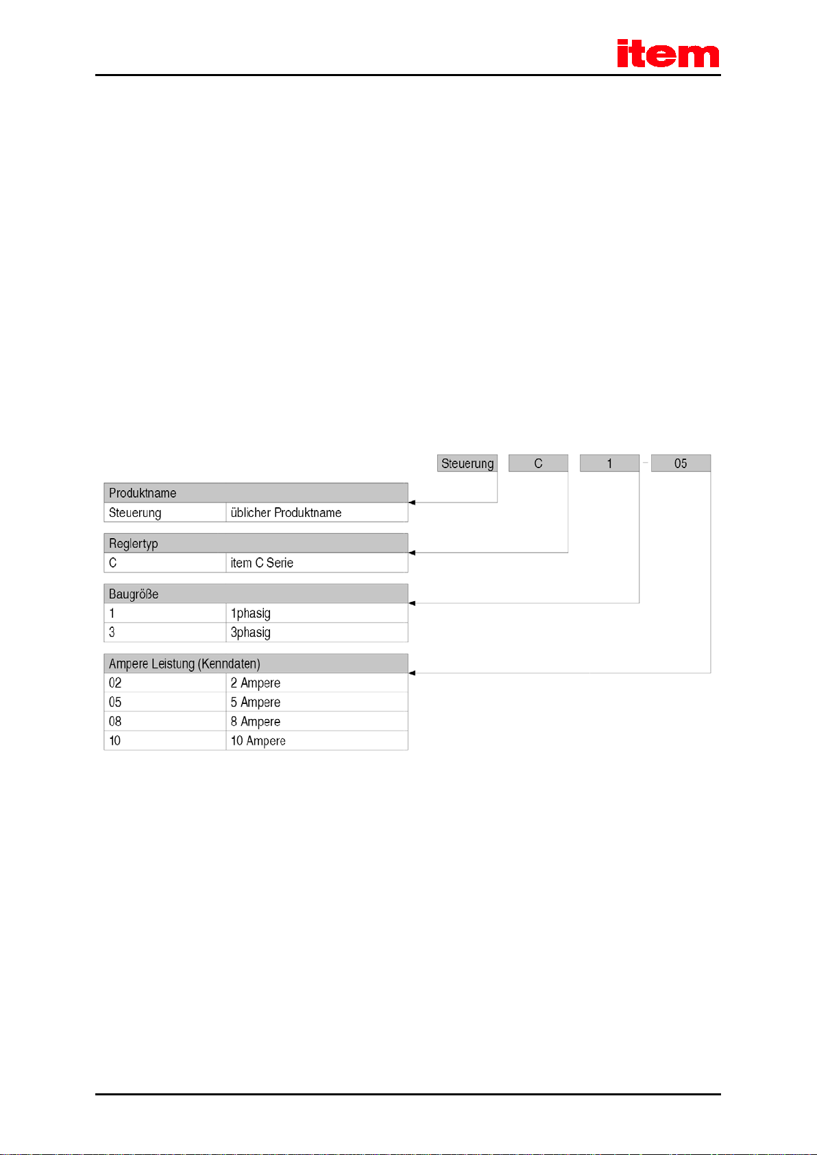
The series includes types with single-phase and three-phase supply.
Type key:
item servo positioning controller C 1-05 (example)
Figure 1: Type key
Page 29

Product description
All item Servo Positioning Controller C Series devices have the following features:
Space-saving, compact design, directly cascadable.
High control quality due to high-quality sensors, far superior to conventional market standards, and above-average
processor resources.
Full integration of all of the components for the controller and power module, including a USB, Ethernet, and RS232
interface for the PC communication, plus a CANopen interface for the integration into automation systems.
SD card: support of FW downloads (initialisation via boot switches) and the upload and download of parameter sets.
Integrated universal shaft encoder evaluation for the following encoder types:
Resolvers
Incremental encoders with/without commutation signals
High-resolution Sick-Stegmann incremental encoders, absolute encoders with HIPERFACE
®
High-resolution Heidenhain incremental encoders, absolute encoders with EnDat
Compliance with the current CE and EN standards without any additional external measures.
Device design as per UL standards, cULus-certified.
Completely closed, EMC-optimised metal housing for mounting on conventional switch cabinet mounting plates. The
devices have an IP20 degree of protection.
Integration of all of the required filters, e.g. line filters, motor output filters, filters for the 24 V supply, and filters for the
inputs and outputs, into the device in order to ensure compliance with the EMC regulations during the operation (1
st
environment with limited availability in accordance with EN 61800-3).
Integrated braking resistor. External resistors can be connected for higher levels of braking energy.
Automatic identification of externally connected braking resistors.
Complete electrical isolation of the controller module and power output stage in accordance with EN 61800-5-1.
Electrical isolation of the 24 V potential section with the digital inputs and outputs and the analogue electronic system
and electronic control system.
The device can be used as a torque controller, speed controller, or position controller.
Integrated positioning control with a wide range of functions as per "CAN in Automation (CiA) DSP402" plus numerous
additional application-specific functions.
Jerk-free or time-optimal positioning, relative or absolute with regard to a reference point.
Point-to-point positioning with and without smooth position transitions.
Speed- and angle-synchronous operation with an electronic gear unit via the incremental encoder input or fieldbus.
Extensive modes of operation for synchronisation.
Numerous homing methods.
Jogging mode.
Teach-in mode.
Short cycle times, 50 µs (20 kHz) in the current control circuit and 100 µs (10 kHz) in the speed control circuit.
Switchable clock frequency for the power output stage.
Page 30
 Loading...