

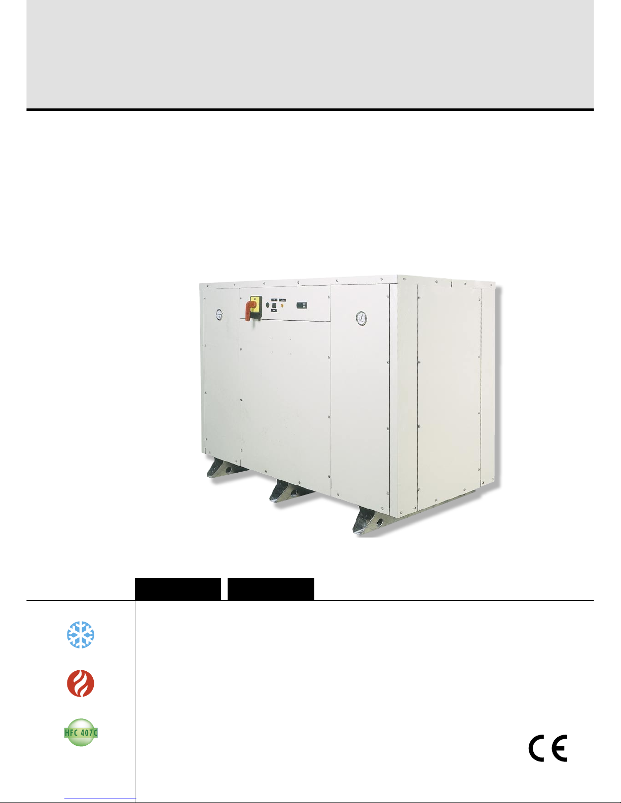
Itelco-Clima CWP-HP, CWP-RC, CWP-CO Installation And Maintenance Manual
English
Water cooled water chillers : cooling only, condenserless and heat pump
versions
Refroidisseurs de liquide à condensation par eau : versions froid seul, sans
condenseur et pompe à chaleur
Installation and maintenance manual
Manuel d’installation et de maintenance
IOM CWP-N.1GBF
Date : May / Mai 2006
Supersedes / Annule et remplace : IMW 910.2M/12.01
CWP-CO/CWP-RC/CWP-HP
02 ÷ 35
8
136 kW
9
164 kW
Français
Page 1
Table of contents
English
1 FOREWORD
1.1 Introduction 2
1.2 Warranty 2
1.3 Emergency stop/Normal stop 2
1.4 An introduction to this manual 2
2 SAFETY
2.1 Foreword 3
2.2 Definitions 3
2.3 Access to the unit 4
2.4 General precautions 4
2.5 Precautions against residual risks 4
2.6 Precautions during maintenance
operations 5
2.7 Safety labels 6
2.8 Safety regulations 7
3 TRANSPORT, LIFTING
AND POSITIONING
3.1 Inspection 10
3.2 Unit Handling 10
3.3 Anchoring 10
3.4 Storage 10
4 INSTALLATION
4.1 Positioning of the unit 11
4.2 Vibration Isolators 11
4.3 External hydraulic circuit 11
4.4 Hydraulic connection
of the condenser 12
4.5 Hydraulic connection 13
4.6 Power supply 13
4.7 Electrical connections 13
5 START-UP
5.1 Preliminary check 14
5.2 Start-up 14
5.3 Checking the operation 15
5.4 Delivery to the customer 15
6 CONTROL SYSTEM
6.1 CWP Control system µchiller 16
6.2 High Pressure Control 18
6.3 Low Pressure Control 18
6.4 Heat Exchanger Heater Thermostat 18
6.5 Pressostatic Valve Kit (Optional) 18
7 GENERAL DESCRIPTION
7.1 Introduction 19
7.2 General Specifications 19
7.3 Compressors 19
7.4 Refrigeration circuits 19
7.5 Evaporator 19
7.6 Condenser (except for CWP-RC) 19
7.7 Switchboard 19
8 TECHNICAL DATA
8.1 Pressure drops 23
8.2 Technical data 24
8.3 Electrical data 29
8.4 Overall dimensions 30
8.5 Service spaces 33
9 MAINTENANCE
9.1 General requirements 34
9.2 Planned maintenance 34
9.3 Refrigerant charge 35
9.4 Compressor 35
9.5 Condenser 35
9.6 Dehydrating filter 35
9.7 Sight glass 35
9.8 Thermostatic expansion valve 36
9.9 Evaporator 36
10 TROUBLESHOOTING 37
11 SPARE PARTS
11.1 Spare part list 39
11.2 Oil for compressors 39
11.3 Wiring diagrams 39
12 DISMANTLING, DEMOLITION
AND SCRAPPING
12.1 Generalities 40
Table of contents
Manuale CWP 4.11.2005 11:55 Pagina 1
Page 2
Foreword
1 FOREWORD
1.1 Introduction
Itelco-Clima units, manufactured to state-of-the-art design and implementation standards, ensure top performance, reliability and fitness to any type of airconditioning systems.
These units are designed for cooling water (and for
water heating in heat pump models) and are unfit for
any purposes other than those specified in this manual.
This manual includes all the information required for
a proper installation of the units, as well as the relevant operating and maintenance instructions.
It is therefore recommended to read this manual
carefully before installation or any operation on the
machine. The chiller installation and maintenance
must be carried out by skilled personnel only (where
possible, by one of Itelco-Clima’s Authorised Service
Centers).
The manufacturer may not be held liable for any
damage to people or property caused by improper
installation, start-up and/or improper use of the unit
and/or failure to implement the procedures and instructions included in this manual.
1.2 Warranty
These units are delivered complete, tested and ready
for being operated. Any form of warranty will become null and void in the event that the appliance is
modified without Itelco-Clima’s preliminary written
authorisation.
This warranty shall apply providing that the installation instructions have been complied with (either issued by’Itelco-Clima, or deriving from the current
practice), and the Form 1 (“Start-up”) has been filledin and mailed to ’Itelco-Clima (attn. After-Sales Service).
In order for this warranty to be valid, the following
conditions shall be met:
h
The machine must be operated only from Authorised After-Sales Service.
h
Maintenance must be performed only by skilled
personnel - from one of Itelco-Clima’s Authorised
After-Sales Centers.
h
Use only original Itelco-Clima spare parts.
h
Carry out all the planned maintenance provided
for by this manual in a timely and proper way.
Failure to comply with any of these conditions will
automatically void the warranty.
1.3 Emergency stop / Normal stop
The emergency stop of the unit can be enabled using
the master switch on the control panel (move down
the lever).
For a normal stop, press the relevant push-buttons.
To restart the appliance, follow the procedure de-
tailed in this manual.
1.4 An introduction to the manual
For safety reasons, it is imperative to follow the instructions given in this manual. In case of any damage caused by non-compliance with these instructions, the warranty will immediately become null and
void.
Conventions used throughout the manual:
The Danger sign recalls your attention to a
certain procedure or practice which, if not
followed, may result in serious damage to
people and property.
The Warning sign precedes those procedures that, if not followed, may result in serious damage to the appliance.
The Notes contain important observations.
The Useful Tips provide valuable information that optimises the efficiency of the appliance.
This manual and its contents, as well as the documentation which accompanies the unit, are and remain the property of Constructor, which reserves any
and all rights thereon. This manual may not be
copied, in whole or in part, without Constructor’s
written authorization.
USEFUL TIPS
Manuale CWP 4.11.2005 11:55 Pagina 2
Page 3
English
Safety
2 SAFETY
2.1 Foreword
These units must be installed in conformity with the
provisions of Machinery Directive 98/37/EC, Low
Voltage Directive 73/23/EC, Pressure Vessels Directive 97/23/EC, Electromagnetic Interference Directive 89/336/EC, as well as with other regulations
applicable in the country of installation. If these provisions are not complied with, the unit must not be
operated.
The unit must be grounded, and no installation and/or maintenance operations may
be carried out before deenergising the electrical panel of the unit.
Failure to respect the safety measures mentioned
above may result in electrocution hazard and fire in
the presence of any short-circuits.
Inside the heat exchangers, the compressors and the refrigeration lines, this unit
contains liquid and gaseous refrigerant under pressure. The release of this refrigerant
may be dangerous and cause injuries.
The units are not designed to be operated
with natural refrigerants, such as hydrocarbons. Itelco-Clima may not be held liable
for any problems deriving from the replacement of original refrigerant or the introduction of hydrocarbons.
Itelco-Clima units are designed and manufactured
according to the requirements of European Standard
PED 97/23/EC (pressure vessels).
– The used refrigerants are included in group II (non-
hazardous fluids).
– The maximum working pressure values are men-
tioned on the unit’s data plate.
– Suitable safety devices (pressure switches and safe-
ty valves) have been provided, to prevent any
anomalous overpressure inside the plant.
– The vents of the safety valves are positioned and
oriented in such a way as to reduce the risk of contact with the operator, in the event that the valve is
operated. Anyway, the installer will convey the discharge of the valves far from the unit.
It is the User’s responsibility to ensure that
the unit is fit for the conditions of intended
use and that both installation and maintenance are carried out by experienced personnel, capable of respecting all the recommendations provided by this manual. It is
important that the unit is adequately supported, as detailed in this manual. Noncompliance with these recommendations
may create hazardous situations for the
personnel.
The unit must rest on a base which meets
the characteristics specified in this manual;
a base with inadequate characteristics is
likely to become a source of serious injury
to the personnel.
The unit has not been design to withstand
loads and/or stress that may be transmitted
by adjacent units, piping and/or structures.
Each external load or stress transmitted to
the unit may break or cause breakdowns in
the unit’s structure, as well as serious dangers to people. In these cases, any form of
warranty will automatically become null
and void.
The packaging material must not be disposed of in the surrounding environment or
burnt.
2.2 Definitions
OWNER: means the legal representative of the company, body or individual who owns the plant where
Itelco-Clima unit has been installed; he/she has the
responsibility of making sure that all the safety regulations specified in this manual are complied with,
along with the national laws in force.
INSTALLER: means the legal representative of the
company who has been given by the owner the job
of positioning and performing the hydraulic, electric
and other connections of Itelco-Clima unit to the
plant: he/she is responsible for handling and properly installing the appliance, as specified in this manual and according to the national regulations in
force.
OPERATOR: means a person authorised by the owner to do on Itelco-Clima unit all the regulation and
control operations expressly described in this manual, that must be strictly complied with, without exceeding the scope of the tasks entrusted to him.
Manuale CWP 4.11.2005 11:55 Pagina 3

Page 4
Safety
ENGINEER: means a person authorised directly by
Itelco-Clima or, in all EC countries, excluding Italy,
under his full responsibility, by the distributor of Itelco-Clima product, to perform any routine and extraordinary maintenance operations, as well as any
regulation, control, servicing operations and the replacement of pieces, as may be necessary during the
life of the unit.
2.3 Access to the unit
The unit must be placed in an area which can be accessed also by OPERATORS and ENGINEERS; otherwise the unit must be surrounded by a fence at not
less than 2 meters from the external surface of the
machine.
OPERATORS and ENGINEERS must enter the fenced
area only after wearing suitable clothing (safety
shoes, gloves, helmet etc.). The INSTALLER personnel
or any other visitor must always be accompanied by
an OPERATOR.
For no reason shall any unauthorised personnel be
left alone in contact with the unit.
2.4 General precautions
The OPERATOR must simply use the controls of the
unit; he must not open any panel, other than the one
providing access to the control module.
The INSTALLER must simply work on the connections
between plant and machine; he must not open any
panels of the machine and he must not enable any
control.
When you approach or work on the unit, follow the
precautions listed below:
h
do not wear loose clothing or jewellery or any other accessory tat may be caught in moving parts
h
wear suitable personal protective equipment
(gloves, goggles etc.) when you have to work in
the presence of free flames (welding operations) or
with compressed air
h
if the unit is placed in a closed room, wear ear protection devices
h
cut off connecting pipes, drain them in order to
balance the pressure to the atmospheric value before disconnecting them, disassemble connections,
filters, joints or other line items
h
do not use your hands to check for any pressure
drops
h
use tools in a good state of repair; be sure to have
understood the instructions before using them
h
be sure to have removed all tools, electrical cables
and any other objects before closing and starting
the unit again
2.5 Precautions against residual risks
Prevention of residual risks caused by the
control system
h
be sure to have perfectly understood the operating
instructions before carrying out any operation on
the control panel
h
when you have to work on the control panel, keep
always the operating instructions within reach
h
start the unit only after you have checked its perfect
connection to the plant
h
promptly inform the ENGINEER about any alarm
involving the unit
h
do not reset manual restoration alarms unless you
have identified and removed their cause
Prevention of residual mechanical risks
h
install the unit according to the instructions provided in this manual
h
carry out all the periodical maintenance operations prescribed by this manual
h
wear a protective helmet before accessing the interior of the unit
h
before opening any panelling of the machine,
make sure that it is secured to it by hinges
h
do not remove the guards from moving elements
while the unit is running
h
check the correct position of the moving elements’
guards before restarting the unit
Prevention of residual electrical risks
h
connect the unit to the mains according to the instructions provided in this manual
h
periodically carry out all the maintenance operations specified by this manual
h
disconnect the unit from the mains by the external
disconnecting switch before opening the electrical
board
h
check the proper grounding of the unit before startup
h
check all the electrical connections, the connecting
cables, and in particular the insulation; replace
worn or damaged cables
h
periodically check the board’s internal wiring
h
do not use cables having an inadequate section or
flying connections, even for limited periods of time
or in an emergency
Manuale CWP 4.11.2005 11:55 Pagina 4

Page 5
English
Safety
Prevention of other residual risks
h
make sure that the connections to the unit conform
to the instructions provided in this manual and on
the unit’s panelling
h
if you have to disassemble a piece, make sure that
it has been properly mounted again before restarting the unit
h
do not touch the delivery pipes from the compressor, the compressor and any other piping or component inside the machine before wearing protective gloves
h
keep a fire extinguisher fir for electrical appliances
near the machine
h
on the units installed indoor, connect the safety
valve of the refrigeration circuit to a piping network that can channel any overflowing refrigerant
outside
h
remove and leak of fluid inside and outside the unit
h
collect the waste liquids and dry any oil spillage
h
periodically clean the compressor compartment, to
remove any fouling
h
do not store flammable liquids near the unit
h
do not disperse the refrigerant and the lubricating
oil into the environment
h
weld only empty pipes; do not approach flames or
other sources of heat to refrigerant pipes
h
do not bend/hit pipes containing fluids under pressure
2.6 Precautions during maintenance
operations
Maintenance operations can be carried out by authorised technicians only.
Before performing any maintenance operations:
h
disconnect the unit from the mains with the external
disconnecting switch
h
place a warning sign “do not turn on - maintenance in progress” on the external disconnecting
switch
h
make sure that on-off remote controls are inhibited
h
wear suitable personal protective equipment (helmet, safety gloves, goggles and shoes etc.)
To carry out any measurements or checks which require the activation of the machine:
h
work with the electrical board open only for the
necessary time
h
close the electrical board as soon as the measurement or check has been completed
The following precautions must be always adopted:
h
do not scatter the fluids of the refrigeration circuit
in the surrounding environment
h
when replacing an eprom or electronic cards, use
always suitable devices (extractor, antistatic
bracelet, etc.)
h
to replace a compressor, the evaporator, the condensing coils or any other weighty element, make
sure that the lifting equipment is consistent with the
weight to be lifted
h
contact Itelco-Clima for any modifications to the refrigeration, hydraulic or wiring diagram of the
unit, as well as to its control logics
h
contact Itelco-Clima if it is necessary to perform
very difficult disassembly and assembly operations
h
use only original spare parts purchased directly
from Itelco-Clima or the official retailers of the companies on the recommended spare parts list
h
contact Itelco-Clima if it is necessary to handle the
unit one year after its positioning on site or if you
wish to dismantle it.
Manuale CWP 4.11.2005 11:55 Pagina 5

Page 6
Grounding connection - On the electrical
board, adjacent to the connection
Final Test Certificate -
Inside the external door
Fitting identification -
Adjacent to fittings
EIN - INLET
ENTRÉE - ENTRATA
AUS - OUTLET
SORTIE - USCITA
Safety
2.7 Safety labels
The labels below will be affixed to each unit in the indicated point:
Identification of the unit -
Outside, on the right-hand front column
Electrical warning
Adjacent to the master switch
Manuale CWP 4.11.2005 11:56 Pagina 6
Page 7
English
Safety
2.8 Safety regulations
Refrigerant data
Toxicity Low
Contact with skin If sprayed, the refrigerant is likely to cause frost burns. If absorbed by
the skin, the danger is very limited; it may cause a slight irritation, and
the liquid is degreasing. Unfreeze the affected skin with water. Remove
the contaminated clothes with great care - in the presence of frost
burns, the clothes may stick to the skin. Wash with plenty of warm water the affected skin.
In the presence of symptoms such as irritation or blisters, obtain medical attention.
Contact with eyes
Ingestion
Inhalation
Recommendations
Prolonged exposure
Vapours do not cause harmful effects.
The spraying of refrigerant may cause frost burns. Wash immediately
with a proper solution or with tap water for at least 10 minutes, and
then obtain medical attention.
Very unlikely - should something happen, it will cause frost burns.
Do not induce vomiting. Only if the patient is conscious, wash out
mouth with water and give some 250 ml of water to drink. Then, obtain
medical attention.
R407C: remarkable concentrations in the air may have an anaesthetic
effect, up to fainting. The exposure to considerable amounts may cause
irregular heartbeat, up to the sudden death of the patient. Very high
concentrations may result in the risk of asphyxia, due to the reduction in
the oxygen percentage in the atmosphere. Remove the patient to fresh
air and keep warm and at rest.
If necessary, give oxygen. In case of breathing difficulties or arrest, proceed with artificial respiration. In case of cardiac arrest, proceed with
cardiac massage. Then, obtain medical attention.
Semiotics or support therapy is recommended. Cardiac sensitisation
has been observed that, in the presence of circulating catecholamines
such as adrenalin, may cause cardiac arrhythmia and accordingly, in
case of exposure to high concentrations, cardiac arrest.
R407C: a study on the effects of exposure to 50,000 ppm during the
whole life of rats has identified the development of benign testicle tumour. This situation should therefore be negligible for personnel exposed to concentrations equal to or lower than professional levels.
Professional levels
Stability R407C: Not specified
R407C: Recommended threshold: 1000 ppm v/v - 8 hours TWA.
Conditions to avoid Do not use in the presence of flames, burning surfaces and excess hu-
midity.
Safety data: R407C
Hazardous reactions May react with sodium, potassium, barium and other alkaline metals.
Incompatible substances: magnesium and alloys with magnesium concentrations > 2%.
Hazardous decomposition
products
R407C: Halogen acids produced by thermal decomposition and hydrolysis.
Manuale CWP 4.11.2005 11:56 Pagina 7
Page 8
Respiratory system protection
Storage
Protective clothing
Accidental release measures
Disposal
Fire fighting information
Cylinders
Protective fire fighting
equipment
If you are in doubt about the concentration in the atmosphere, it is recommended to wear a respirator approved by an accident-prevention
Authority, of the independent or oxygen type.
Cylinders must be stored in a dry and fresh place, free from any fire
hazard, far from direct sunlight or other sources of heat, radiators etc.
Keep a temperature below 45°C.
Wear overalls, protective gloves and goggles or a mask.
It is important to wear protective clothing and a respirator. Stop the
source of the leak, if you can do this without danger. Negligible leaks
can be left evaporating under the sun, providing that the room is well
ventilated. Considerable leaks: ventilate the room. Reduce the leak with
sand, earth or other absorbing substances. Make sure that the liquid
does is not channelled into gutters, sewers or pits where the vapours
are likely to create a stuffy atmosphere.
The best method is recovery and recycling. If this method is not practicable, dispose according to an approved procedure, that shall ensure
the absorption and neutralization of acids and toxic agents.
R407C: Not flammable in the atmosphere.
In case of fire, wear an independent respirator and protective clothing.
The cylinders, if exposed to fire, shall be cooled by water jets; otherwise, if heated, they may explode.
General precautions Do not inhale concentrated vapours. Their concentration in the atmos-
phere should not exceed the minimum preset values and should be
maintained below the professional threshold. Being more weighty than
the air, the vapour concentrates on the bottom, in narrow areas. Therefore, the exhaust system must work at low level.
Safety
Manuale CWP 4.11.2005 11:56 Pagina 8
Page 9
English
Safety
Refrigerant oil data Safety data: Polyolester oil (POE)
Classification
Contact with skin
Contact with eyes
Ingestion
Inhalation
Conditions to avoid
Protection of the respiratory
system
Protective clothing
Accidental release measures
Disposal
Fire fighting information
Cylinders
Fire fighting protective
equipment
Not harmful
May cause slight irritation. Does not require first aid measures. It is recommended to follow usual personal hygiene measures, including washing the exposed skin with soap and water several times a day. It is also
recommended to wash your overalls at least once a week.
Wash thoroughly with a suitable solution or tap water.
Seek medical advice immediately.
Seek medical advice immediately.
Strong oxidising substances, caustic or acid solutions, excess heat.
May corrode some types of paint or rubber.
Use in well ventilated rooms.
Always wear protective goggles or a mask. Wearing protective gloves
is not mandatory, but is recommended in case of prolonged exposure
to refrigerant oil.
It is important to wear protective clothing and, especially, goggles.
Stop the source of the leak. Reduce the leak with absorbing substances
(sand, sawdust or any other absorbing material available on the market).
The refrigerant oil and its waste will be disposed of in an approved incinerator, in conformity with the provisions and the local regulations
applicable to oil waste.
In the presence of hot liquid or flames, use dry powder, carbon dioxide
or foam. If the leak is not burning, use a water jet to remove any
vapours and to protect the personnel responsible for stopping the leak.
The cylinders exposed to a fire will be cooled with water jets in case of
fire.
In case of fire, wear an independent respirator.
Manuale CWP 4.11.2005 11:56 Pagina 9
Page 10
Transport, Lifting and Positioning
3 TRANSPORT, LIFTING
AND POSITIONING
Refrigerators are supplied assembled. The equipment are full of refrigerant and oil, in the quantity required for a proper operation.
3.1 Inspection
When the unit is delivered, it is recommended to
check it carefully and to identify any damage occurred during transportation. The goods are shipped
ex-factory, at the buyer’s risk. Check that the delivery
includes all the components listed in the order.
In case of damage, note it down on the carrier’s delivery note and issue a claim according to the instructions provided in the delivery note.
In the presence of any serious damage, that does not
affect the surface only, it is recommended to inform
Itelco-Clima immediately.
Please note that Itelco-Clima may not be held liable
for any damage to the equipment during transportation, even though the carrier has been appointed by
the factory.
3.2 Unit Handling
Sharp edges and coil surfaces are a potential hazard. Avoid contact with them.
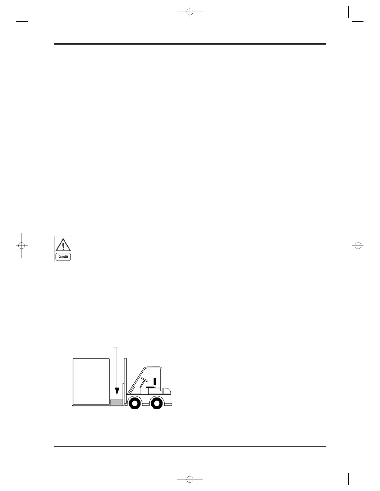
Be careful to avoid rough handling of the unit. Do
not push or pull the unit anything other than the
base. Block the pushing vehicle away from the unit
to prevent damage to the sheet metal cabinet and
end frame (see picture 1).
3.3 Anchoring
It is not essential to secure the unit to the foundations,
unless in areas where there is a serious risk of earthquake, or if the appliance is installed on the top of a
steel frame.
3.4 Storage
When the unit is to be stored before installation,
adopt a few precautions to prevent any damage or
risk of corrosion or wear:
h
plug or seal every single opening, such as water
fittings
h
do not store the appliance in a room where the
temperature exceeds 50°C for the units using
R407C and, if possible, do not expose to direct
sunlight
h
it is recommended to store the unit in a roof where
traffic is minimized, to prevent the risk of accidental damage
h
the unit must not be washed with a steam jet
h
take away and leave to the site manager all the
keys providing access to the control board
Finally, it is recommended to carry out visual inspections at regular intervals.
Blocking required across
(full width)
Picture 1
Manuale CWP 4.11.2005 11:56 Pagina 10
Page 11
English
Installation
4 INSTALLATION
4.1 Positioning of the unit
Before installing the unit, make sure that the
structure of the building and/or the supporting surface can withstand the weight of the
appliance. The weights of the units are listed in Chapter 8 of this manual.
These units have been designed for outdoor installation on a solid surface. Standard accessories include
antivibrating rubber supports, that must be positioned under the base.
When the unit is to be installed on the ground, it is
necessary to provide a concrete base, to ensure a
uniform distribution of the weights.
As a general rule, no special sub-bases are required.
However, if the unit is to be installed on the top of inhabited rooms, it is advisable to rest it on vibration
isolators, that will minimise the transmission of any
vibration to the structures.
To choose the place of installation of the unit, bear in
mind that the place of installation must be have all
the necessary spaces for air circulation and maintenance operations (see Chapter 9).
4.2 Vibration Isolators
Vibration isolators are recommended for all roof
mounted installations or wherever vibration transmission is a consideration (see chapter “Dimensional
Data” for the location of each isolator).
Vibration eliminators in all water piping connected
to the units are recommended to avoid straining the
piping and transmitting vibration and noise.
4.3 External hydraulic circuit
The external hydraulic circuit must ensure
the water flow to the evaporator under any
working conditions and with any adjustment.
The external hydraulic circuit should consist of the following elements:
h
A circulation pump which delivers a sufficient water flow and discharge head.
h
The capacity of the primary hydraulic circuit
should not be less than 7 litres/KW of cooling capacity, in order to prevent the repeated start-up of
the compressor and any damage to it. If the water
capacity in the primary piping of the circuit and in
the evaporator is lower than this value, an insulated storage tank shall be installed.
h
A membrane expansion vessel provided with safety valve with vent, that must be visible.
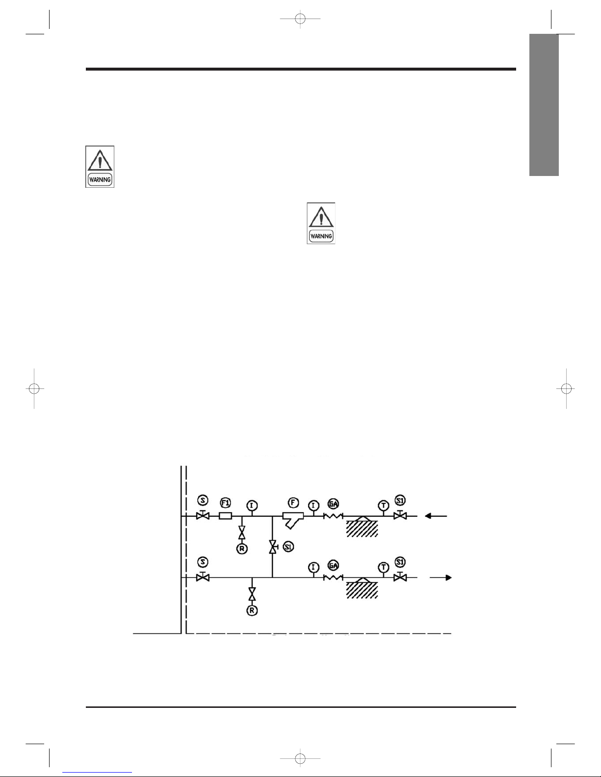
Legends:
I: Pressure gauge connection
S/S1: Gate valve
Fl: Flow meter
GA: Flexible hoses
R: Drain cock
T: Thermometer
F: Filter
Flow meter installation
Unit
Connection diagram
External hydraulic circuit
Manuale CWP 4.11.2005 11:56 Pagina 11

Page 12
The capacity of the expansion vessel must
allow for an expansion of at least 2% of the
volume of the fluid in the circuit (evaporator, piping, user circuit and standby tank, if
any). The expansion vessel needs not be
isolated, because no water can circulate inside it.
h
A flow meter, to disable the appliance when the
water is not circulating.
The flow meter shall be connected (terminals 7-8).
To install the flow meter, conform to the manufacturer’s instructions.
As a general rule, the flow meter must be mounted
on a horizontal pipe, and its distance from the
curves must be 10 times the diameter of the pipe, far
from valves or other components that may hinder the
water flow upstream of or downstream from the flow
meter.
h
The air exhaust valves must be mounted in the
highest point of the piping.
h
The stop valves must be mounted on the water inlet/outlet piping of the evaporator and the heat recovery condenser.
h
The drain points (provided with plugs, cocks etc.)
must be positioned in the lowest point of the piping.
Furthermore:
h
Provide the evaporator with a by-pass circuit
equipped with valve, to wash the plant.
h
Insulate the piping, to prevent the risk of heat loss.
h
Install a filter on the suction side of the evaporator
or the heat recovery condenser.
Before filling the circuit, it is important to
check that it is free from any foreign matter,
sand, gravels, rust, welding deposits, waste
and other materials that may damage the
evaporator.
When cleaning the lines, it is recommended to create a circuit by-pass. It is important to mount a filtering medium (30 mesh) upstream of the chiller.
If necessary, the water required to fill the
circuit must be treated to obtain the requested PH.
Installation
4.4 Hydraulic connection
of the condenser
The external hydraulic circuit must ensure
the water flow to the condenser under any
working or adjustment conditions.
The cooling of the units is generally ensured by connecting the condenser to a cooling tower, though the
units can be cooled also with well water.
In the presence of a water-cooled condenser, it is
necessary to check the flow rate and/or the temperature of the cooling fluid that flows through the condenser, so as to maintain the refrigerant pressure at
values that can ensure a satisfactory operation.
When a cooling tower is used, the simplest regulation methods consist of checking the operation or the
speed of the fan or the air volume, by means of a
damper, once the pilot thermostat has been installed
in the basin of the tower.
Alternatively, or if no water from a cooling tower is
used, you can adopt a recirculaton system provided
with a 3-way valve.
This circuit shall consist of:
h
A circulation pump that can ensure the necessary
capacity and discharge head.
h
A flow meter to turn off the appliance when no water is circulating.
The flow meter must be connected in series,
as shown in the wiring diagram of the control panel.
To install the flow meter, follow the manufacturer’s
instructions.
As a general rule, the flow meter shall be mounted
on a horizontal pipe, at a distance from the curves
equal to 10 times the diameter of the pipe and far
from valves or other components that are likely to
hinder the water flow upstream of or downstream
from the flow meter.
h
The bleed valves must be mounted on the highest
point of the piping.
h
The stop valves must be mounted on the piping of
the water entering/leaving the condenser.
h
The discharge points (provided with plugs, cocks
etc.) must be arranged in the lowest point of the
piping.
Manuale CWP 4.11.2005 11:56 Pagina 12
 Loading...