

Page 1
MAGNETIC TAPE
WORD
PROCESSOR
UD002441-1
FIELD
ENGINEERING
DIVISION
SEPT., 1972
Page 2

Page 3

This information
is
current
as
of
September 1972.
ITEL
CORPORATION
FIELD
ENGINEERING
DIVISION
Technical Support Operations
10435 North Tantau Avenue
Cupertino,
California 95014
Tel: (408) 257-6220 TWX 910-338-0280
Printed
in
U.S.A.
September
1972
Copyright(£)
1972
Page 4

Page 5
Chapter
1
2
3
4
2441-1
CONTENTS
GENERAL
INFORMATION.
1. 1 Introduction
1. 2 Manual
Content
1.
2.
1
Chapter
1,
General
Information.
1.
2.2
Chapter
2,
Installation.
1.
2. 3
Chapter
3,
Operation
.
1.
2. 4
Chapter
4,
Theory
of
Operation.
1.
2. 5
Chapter
5,
Maintenance
1.
2.
6
Chapter
6,
Checks
and
Adjustments
1.
2.7
Chapter
7,
Error
Analysis
1.
2.8
Chapter
8,
Replacement
Procedures
1.
2.9
Chapter
9,
Diagrams
1. 3 System
Description
1.
3.1
Microprocessor
1.3~2
Keyboard
.
1.
3.
3
1.
3.4
1.4
Printer.
Ma
gnetic
Tape
Transports
Specifications.
INS TA
LLA
TION .
2. 1
Unpacking.
2.1.
1
Unpacking
the
Typewriter
Unit
2.1.2
Unpacking
the
Console
Unit
.
2. 2
System
Interconnections
2. 3 Preoperational
Checkout
.
2.3.1
Power
Supply
Voltage
Checkout.
2.3.2
System
Diagnostic
Checkout
.
OPERATION
.
3.1
Keys,
Controls,
Indicators
and
Alarms
.
3.
1.
1
Basic
Operation
Keys
.
3.
1.
2 Mode
Keys
.
3.
1.
3
Action
Keys
3.
1.
4
Encoded
Function
Keys.
3.
1.
5
Console
Controls
and
Indicators.
3.
1.
6
Alarms.
3.2
Operating
Instructions
.
THEORY
OF
OPERA
TION .
4. 1
Functional
Description
.
4. 2 Microprocessor.
4.2.1,
Read
Only
Memory
(ROM)
Program
4.2.2
ROM
Address
Register.
Page
1-1
1-1
1-1
1-1
1-2
1-2
1-2
1-2
1-2
1-2
1-2
1-2
1-2
1-3
1-3
1-4
1-4
1-5
2-1
2-1
2-1
2-1
2-3
2-5
2-5
2-7
3-1
3-1
3-1
3-4
3-6
3-8
3-11
3-12
3-13
4-1
4-1
4-1
4-1
4-6
i
Page 6
CONTENTS (CONT)
Chapter
5
4.2.3
4.2.4
4.2.5
4. 3 Buffer
4.4
4.5
4.6
4.7
4.8
4.9
4.10
4.11
4.12
4.13
MAINTENANCE .
5. 1
5.2
5.2.1
5.2.2
5.
3
5.3.1
5.
3.2
5.4
5.4.1
5.4.2
5.4.3
Return
General
Arithmetic
Tape
Write
Read
Tape
Motor
Keyboard
Printer
Miscellaneous,
Display
DC
Power
Safety
Maintenance
Objectives.
Basic
Tools
Tools
Test
Power
Voltage
Logic
Use
Address
I/O
and
Control
Encode
Decode
Read/Write
Control.
Interface
Interface.
Panel
Supplies
Precautions
Considerations
and
Servicing
Equipment
Supply
Levels
Levels
of
Probes
Purpose
Logic
Buffer
.
.
and
Clock
.
Philosophy
Voltage
.
Register
(GP)
and
Unit
(ALU) .
Control
Tape
.
and
Aids
.
Read
IC .
.
Main
(M)
Only.
Registers
Page
4-7
4-8
4-8
4-8
4-9
4-9
4-9
4-10
4-10
4-12
4-12
4-13
4-13
4-13
5-1
5-1
5-1
5-1
5-1
5-2
5-2
5-2
5-6
5-6
5-6
5-7
ii
6
CHECKS AND
6.1
6.2
6.3
6.4
6.5
6.6
6. 7
6.8
6.9
6.10
6.11
6.12
6.13
6.
6.
6.
General.
PDA
ROM
Branch
Branch
PDA
G-Registers
H-Registers
ALU
Buffers
Data
Data
Keyboard
14
Printer
15
Transport
15.1
Installation
Test
Test
Test
Bus
Bus
Run
ADJUSTMENTS
·
Test
on
Data
·
Test
Test
.
Test
·
Test
Test
Forward
.
Out
(Lamp)
In
(Thumbwheel)
Strobe
Tests
Test
.
. . .
Normal
Test.
Test
Test
6-1
6-1
6-1
6-6
6-7
6-9
6-10
6-10
6-11
6-12
6-13
6-14
•
6-15
6-16
6-17
6-18
6-18
2441-1
Page 7
CONTENTS (CONT)
Chapter
7
8
6.15.2
6.15.3
6.15.4
6.15.5
6.15.6
ERROR
7.1
7.2
Run
Reverse
Run
Forward
Run
Reverse
Speed
Normal
ANALYSIS .
General.
Recommended
REPLACEMENT
8.1
8. 2
8.3
8.4
8.4.
8.4.2
8.4.3
8.4.4
8.4.5
General.
Printer
Keyboard
Transport
1
Head
Motor
Lock
BOT/EOT
Cassette
and
Removal
Assembly
Solenoid
Installation
Normal
Fast
Fast
Tests
Write
.
Forward
Troubleshooting
PROCEDURES
and
Removal
Removal
and
and
Removal
Removal
and
Removal
Sensor
In
Place
Assembly
Switch
Test
Test
Test
.
Test
Installation
Installation.
Installation
and
Installation.
and
and
Sequence.
Installation.
Installation
Removal
File
Protect
and
Installation.
Switch
Page
6-20
6-21
6-22
6-23
6-26
7-1
7-1
7-1
8-1
8-1
8-1
8-1
8-2
8-4
8-6
8-6
8-7
Removal
8-8
9 DIAGRAMS
9. 1
9.2
Figure
1-1
1-2
2-1
2-2
2-3
2-4
2-5
3-1
3-2
3-3
3-4
3-5
4-1
4-2
4-3
Magnetic
Simplified
Typewriter
Console
Typewriter
System
Power
Basic
Mode
Action
Encoded
Console
Console,
Detailed
K-Page
General.
System
Tape
Wire
Word
System
Unit
Packaging
Unit
Packaging
Cover
Interconnections
Supply
Operation
Interconnect
Keys
Keys.
Keys
Function
Controls
Keys.
and
Right-Hand
System
Memory
Block
Structure
List
ILLUSTRATIONS
Processor.
Block
Removal
Diagram
Panel
Indicators.
Interior
View.
Diagram.
9-1
9-1
9-24
Page
1-1
1-3
2-2
2-2
2-4
2-4
2-6
3-1
3-4
3-6
3-8
3-11
4-2
4-4
4-5
2441-1
iii
Page 8
ILLUSTRATIONS
(CONT)
Figure
4-4
4-5
4-6
4-7
4-8
4-9
5-1
6-1
Major-Page
12-Bit
ROM
Bi-Phase
Motor
System
PDA
PDA
Schematics:
Address
Address
Control
Clock
Controls
Installation
Printer
Keyboard
Miscellaneous,
ROM
ROM
Return
Main
Arithmetic
Buffer
Buffer
Tape
Read
Write
Motor
Cassette
Tape
Display
DC
Keyboard
PDA
PDA
Memory
Word
Register
Serial
Power
Data
Block
Timing
and
Indicators,
Interface
Interface
Program
Address
Address
and
General
Logic
I/O
(Read
Control
Control
Decode
Encode
Control
Heat
Read/Write,
Panel
Supply
Logic
ROM
and
Switch
and
Structure
Format
Diagram
,
(socket
(socket
Clock,
(sockets
Register
Register
Purpose
Unit
Only & Read/Write)
(Read
(Read/Write & Read
(Read/Write & Read
(Read/Write)
(sockets
Sink
Tape
.
Controls
Indicator.
1)
3),
and
IC
(socket
5,
6, 7,
(socket
(socket
(socket
Only & Read/Write)
R/WJ1
,
Read
9)
Register
12) ,
(socket
and
Only
and
8)
,
10) ,
(socket
Only)
Only)
19)
ROJl).
(sockets
4)
11),
(sockets
(sockets
(sockets
(sockets
R/WJ2
13
and
17
18
14
and
and
and
15) .
and
16)
20)
21).
ROJ2)
Page
4-5
4-6
4-7
4-10
4-11
4-14
5-4
6-1
9-2
9-3
9-4
9-5
9-6
9-7
9-8
9-9
9-10
9-11
9-12
9-13
9-14
9-15
9-16
9-17
9-18
9-19
9-20
9-21/9-22
9-23
Table
1-1
2-1
3-1
3-2
iv
Dual
Station
Power
Encoded
Encoded
MTWP
Supply
Function
Function
Voltages.
TABLES
Specifications
Codes
Keys.
Page
.
1-5
2-7
3-5
3-8
2441-1
Page 9
TABLES (CONT)
Table
4-1
4-2
6-1
6-2
6-3
6-4
6-5
6-6
6-7
6-8
6-9
6-10
6-11
7-1
7
-2
8-1
8-2
8-3
Card
Other
PDA
Error
ROM
Branch
Branch
ALU
Buffers
Data
Transport
Speed
Normal
PWA's
Troubleshooting
Transport
Head
BOT/EaT
Cage
Routine
Test
Bus
Assembly
PWA's
Console
Addresses
Tests.
Tests
on
Data
"Error
Test
Out
Tests
Conversions
Write
Affected
Power
Sensor
PWA's
Addresses
.
Test
"Error
Addresses"
"Error
(Lamp)
Forward
Addresses"
Error
.
According
Chart
Connections
Connections
Assembly
Test
Analysis
"Error
.
Addresses"
Sequence
Addresses"
to
Priority.
.
Connections.
Page
4-3
4-3
6-4
6-5
6-7
6-8
.
6-9
6-13
6-14
6-15
6-20
6-24
6-27
7-2
7-3
8-3
8-4
8-7
9-1
Diagrams.
9-1
2441-1
v
Page 10

/
Page 11
CHAPTER 1
1.1
INTRODUCTION
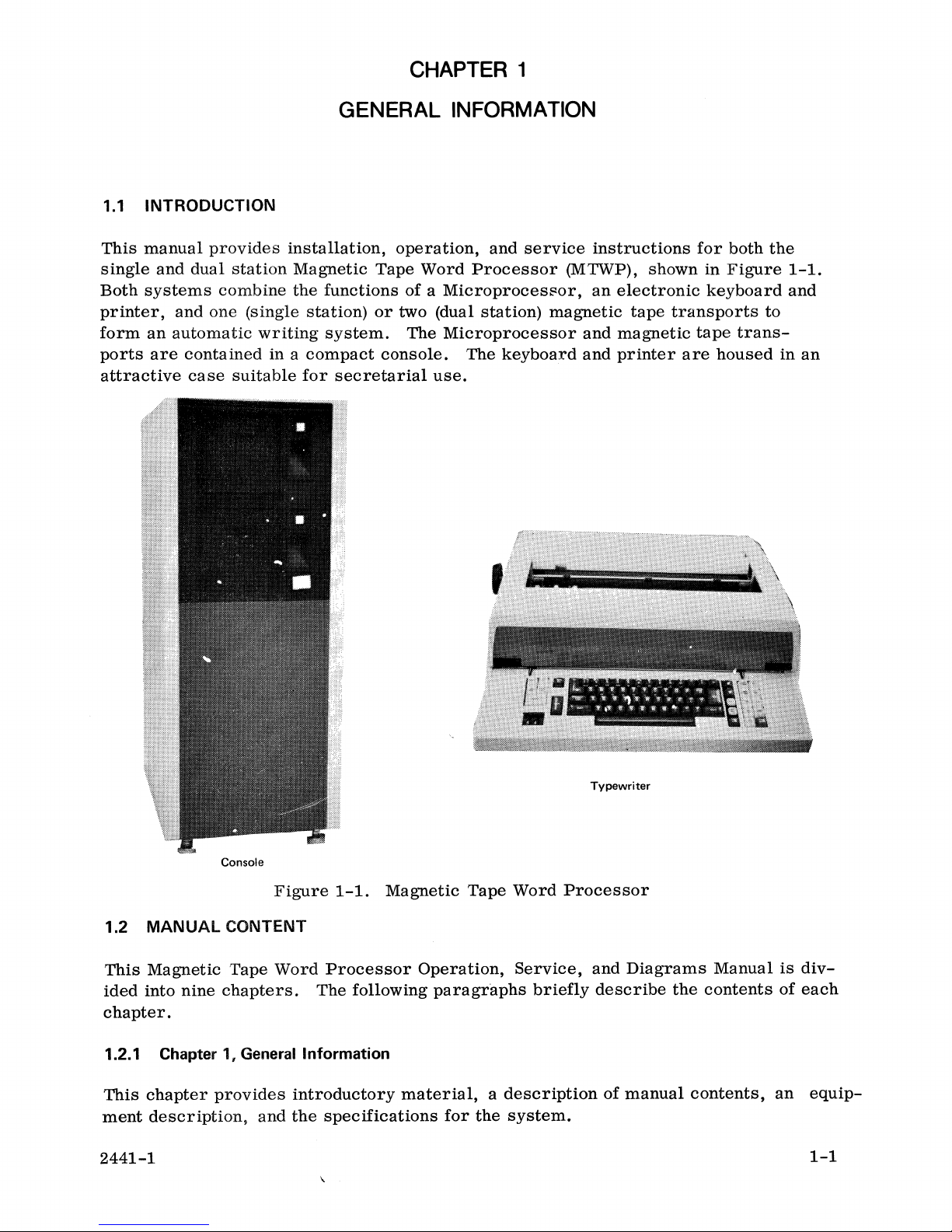
This
manual
single
Both
printer,
form
ports
and
systems
and
an
automatic
are
attractive
provides
dual
station
combine
one
(single
contained
case
suitable
GENERAL
installation,
Magnetic
the
functions
station)
writing
in a compact
system.
for
secretarial
INFORMATION
operation,
Tape
Word
of a Microprocesflor,
or
two (dual
The
Microprocessor
console.
use.
and
Processor
station)
The
keyboard
service
(MTWP) ,
magnetic
instructions
shown
an
electronic
tape
and
magnetic
and
printer
for
both
in
Figure
keyboard
transports
tape
trans-
are
housed
the
to
1-1.
and
in
an
Console
Figure
1.2
This
ided
MANUAL
Magnetic
into
nine
CONTENT
Tape
Word
chapters.
The
chapter.
1.2.1 Chapter 1, General Information
This
ment
chapter
description,
provides
and
introductory
the
2441-1
1-1.
Magnetic
Processor
following
material, a description
specifications
\
Tape
Operation,
paragraphs
for
the
Word
Service,
briefly
system.
Typewriter
Processor
and
Diagrams
describe
of
manual
Manual
the
contents
contents,
is
of
an
diveach
equip-
1-1
Page 12
1.2.2 Chapter 2, Installation
Chapter 2 discusses
installing a system.
vided
1.2.3 Chapter
in
this
chapter
3,
Chapter 3 identifies
and
indicator
1.2.4 Chapter
The
theory
and
timing
1.2.5 Chapter
on
4,
of
operation
diagrams
5,
Chapter 5 outlines
required
1.2.6 Chapter 6, Checks and Adjustments
Electrical
special
and
mechanical
unpacking,
A
preoperation
to
verify
Operation
and
describes
the
console,
Theory of Operation
is
provided
are
used,
Maintenance
safety
tools
precautions,
and
test
inspection,
that
and
where
equipment.
checks
the
the
system
in
and
and
checks
and
system
function
alarm.
this
chapter.
necessary,
presents
adjustments
the
interconnections
adjustments
is
operating
of
each
key
Block
to
support
maintenance
are
contained
procedure
properly.
on
the
keyboard,
diagrams,
the
text.
philosophy,
in
required
is
simplified
and
Chapter
when
also
control
lists
6.
pro-
drawings,
1.2.7 Chapter 7, Error Analysis
This
chapter
1.2.8 Chapter 8, Replacement Procedures
Chapter 8 presents
1.2.9 Chapter 9, Diagrams
This
chapter
Programmed
1.3 SYSTEM DESCRIPTION
The
ITEL
tronic
only
the
system
the
capabilities
single
dual
• A
contains
information
removal
contains
the
Diagnostic
or
dual
for
automatic
station
of
system
the
single
Microprocessor.
and
schematic
Aid
(PDA). The
station
writing.
will
station
designed
installation
Magnetic
be
discussed.
to
diagrams
system
Tape
The
functions
system.
assist
in
procedures.
for
the
wire
Word
Processor,
of
The
dual
The
major
troubleshooting.
system
list
is
as
also
well
included.
(MTWP)
both
are
identical;
station
does,
components
as
those
is
therefore,
however,
of
the
for
an
elec-
extend
system
the
are:
• A
full
duplex
1-2
electronic
keyboard.
2441-1
Page 13
•
An
electronic
printer.
Figure
• Two
1-2
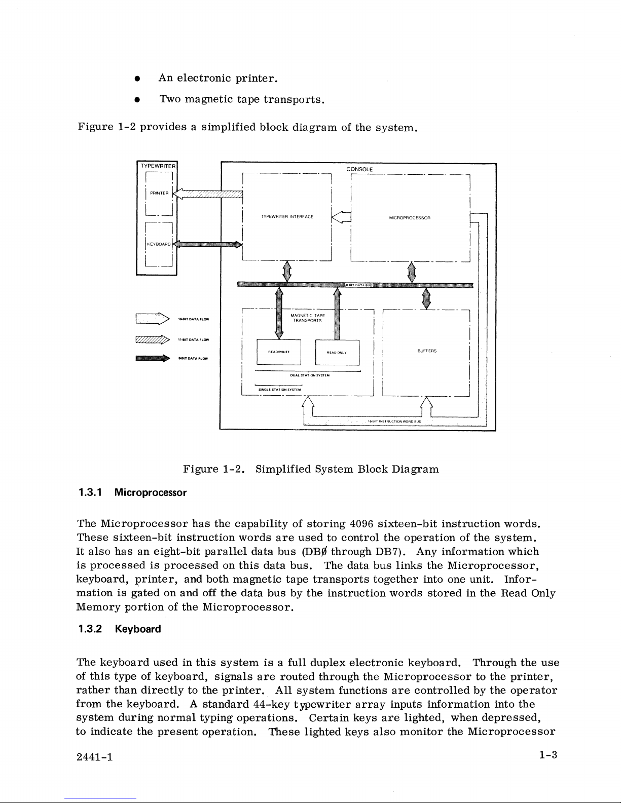
provides a simplified
TYPEWRITER
magnetic
~~
..
alT
DATA
FLOW
tape
transports.
block
1-------1
TYPOWRITER INTERFACE
r-----
LSlNGLE
STATlDN
SYSTEM
-----
diagram
-
__
~
MAGNETIC TAPE
TRANSPORTS
DUAC
...
"ON
ovm.
of
the
system.
CONSOLE
~----------l
II
, , I
k::j
Ii'
, , I
MICROPROCESSOR
L ________ j
----:
___
I .
, I
! i
! i
~
i---
L
__
BUFFERS
_
---l
-~
'
i
I
i
1.3.1 Microprocessor
Microprocessor
The
These
It
is
keyboard,
mation
Memory
1.3.2 Keyboard
The
of
rather
from
system
to
sixteen-bit
also
has
processed
is
gated
portion
keyboard
this
type
than
the
keyboard.
during
indicate
an
eight-bit
is
processed
I?rinter,
on
of
used
of
keyboard,
directly
normal
the
present
Figure
has
instruction
and
and
the
in
to
A
1-2.
the
parallel
on
both
off
the
Microprocessor.
this
system
signals
the
printer.
standard
typing
operation.
Simplified
capability
words
this
magnetic
data
operations.
are
data
bus
data
bus
is a full
are
All
44-key
These
routed
System
of
storing
used
(DB.0
bus.
tape
by
The
transports
the
duplex
through
system
typewriter
Certain
lighted
16 BtT
Block
4096
to
control
through
instruction
functions
keys
DB7). Any
data
bus
together
electronic
the
array
keys
also
INSTRU~TlON
WORD
BUS
Diagram
sixteen-bit
the
operation
links
words
keyboard.
Microprocessor
are
inputs
are
lighted,
monitor
instruction
information
the
Microprocessor,
into one
stored
controlled
information
the
words.
of
the
system.
which
unit.
in
Through
when
Microprocessor
Infor-
the
Read
to
the
by
the
into
depressed,
Only
the
use
printer,
operator
the
2441-1
1-3
Page 14
and
flash
to
key
on
the
keyboard
1.3.3 Printer
The
printer,
character
text
such
six
lines
at a time).
as
per
display
used
letters,
inch
input, output, and
and
each
alarm
as
the
output
It
operates
device
specifications,
(single
space)
or
system
is
discussed
for
at
speeds
contracts,
three
the
up
lines
error
conditions.
in
detail
system,
to 30
characters
etc.
per
inch (double
is
of a serial
The
15-inch
The function
in
Chapter 3 of
per
long
space).
this
type
(prints a single
second
platen
of
manual.
on
general
indexes
each
at
There
feed.
controls
ASCII
direction
1/60
line
1/48
Character
wheels
Two
by
are
code
of
spaces
of
types
the
operator.
Each
are
and
an
an
are
three
motion
for
inch),
(indexes)
inch).
sets
easily
of
carbon.
1.3.4
The
Magnetic
dual
station
store a single
8-bit
word
enroute
these
of
in
the
on
to
the
8-bit
buffer
tape.
basic
is
sent
down
the
next
number
or
an
are
provided
interchanged
ribbon
cartridges
The
Tape
Transports
system
line
of
the
data
printer.
characters.
and
then
printer
motions;
controlled
the
eleven
character
of
printing
ll-bit
that
the
word
paper
in
the
by
are
styles
has
available
two
typewritten
bus,
comes
A
single
Information
outputed, a
carrier,
by
the
system
data
to
be
spaces
which
is
to
form
the
operator.
available
include
lines.
printed,
to
be
of
The
be
moved
specifies
moved
an
88-character
and
single
circulating-type,
information.
from
line
line
either
of
typewritten
from
at a time,
the
the
print
wheel
through
an
data
ii-bit
the
lines
by
the
direction
by
the
these
too
reusable
live-memory,
This
information,
keyboard
information
keyboard
onto
the
(character),
printer
transmit
word
which
the
carrier
paper
feed
print
are
easily
fabric
or
magnetic
is
stored, a line
read/write
and
interface.
either
specifies
(in
multiples
and
number
(in
multiples
wheel.
These
interchangeable
and a single-use
MOS
buffers
in
the
form
tape
can
contain
(R/W)
paper
These
the
7-bit
the
of
of
vertical
of
print
which
of
an
storage
up
to 256
at a time,
magnetic
The
magnetic
20
inches
the
read
directionally
per
second.
the
system,
per
only
tape
transports
second
magnetic
reading
The
functions
are
controlled
and
bidirectionally
tape
at
20
1-4
are
transport
inches
of
each
by
the
capable
searching
(dual
per
second
magnetic
operator
of
unidirectionally
at
70
station
and
tape
from
system
bidirectionally
transport,
the
keyboard.
reading
inches
only)
like
and
per
second.
is
only
searching
any
other
writing
Naturally,
capable
at
70
functions
at
of
uni-
inches
2441-1
of
Page 15
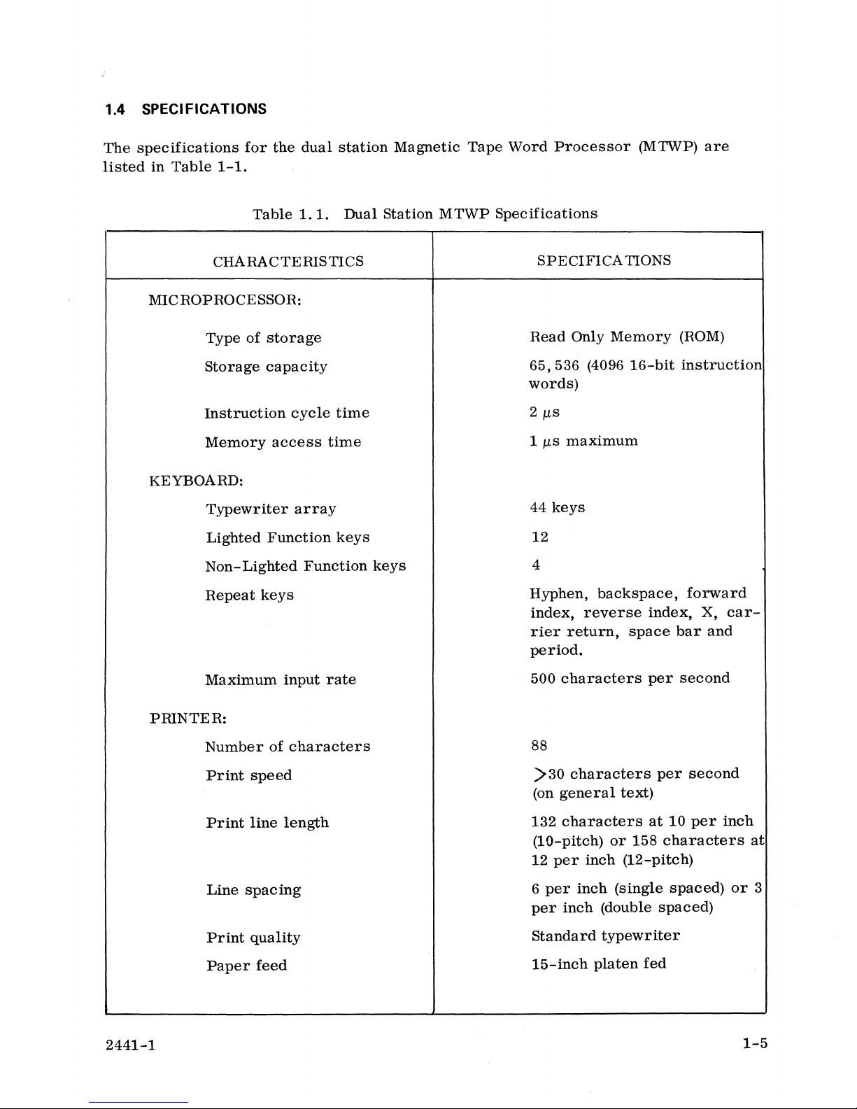
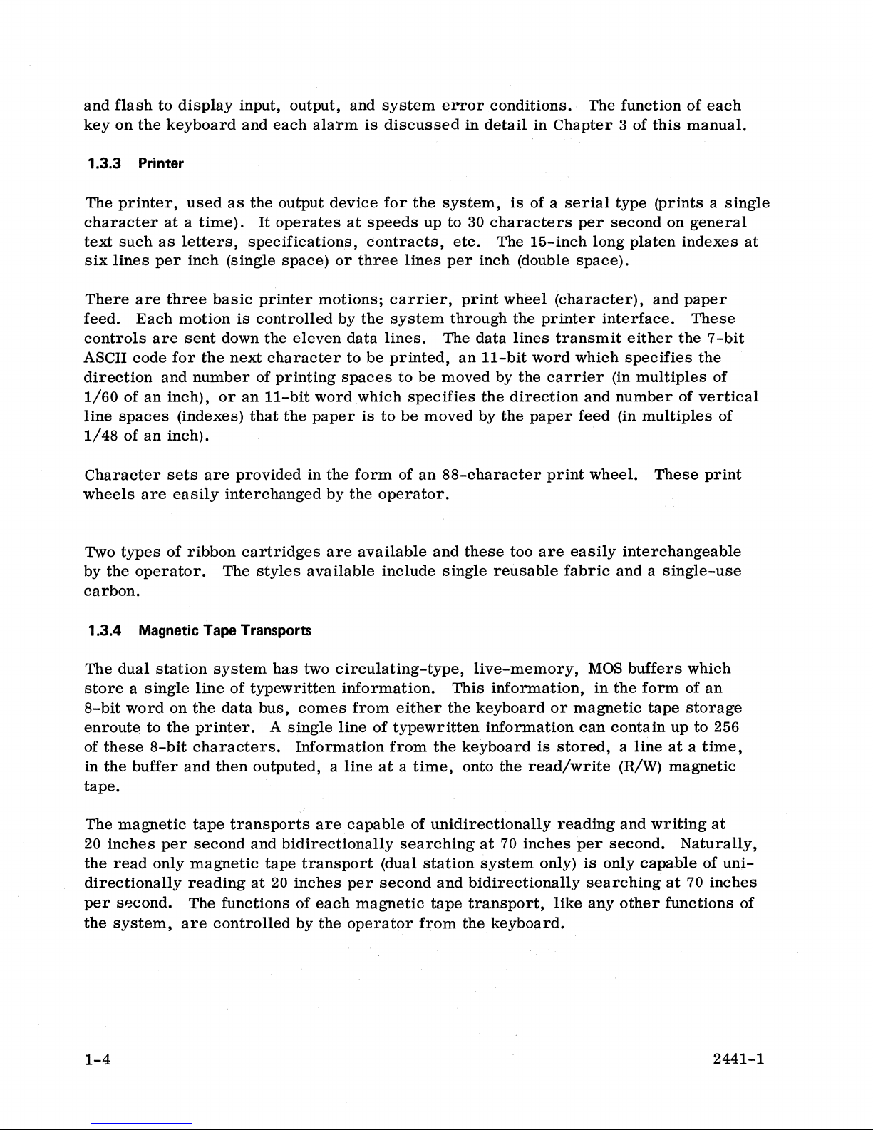
1.4 SPECIFICATIONS
The
specifications
listed
in
Table
for
1-1.
the
dual
station
Magnetic
Tape
Word
Processor
(MTWP)
are
Table
CHARACTERISTICS
MICROPROCESSOR:
Type
of
storage
Storage
Instruction
Memory
capacity
cycle
access
KEYBOARD:
Typewriter
Lighted
array
Function
Non-Lighted
Repeat
keys
1.1.
Dual
time
time
keys
Function
Station
keys
MTWP
Specifications
SPECIFICA
Read
Only
65,536
(4096
words)
2
J.1.s
1
J.1.s
maximum
44
keys
12
4
Hyphen,
index,
rier
reverse
return,
period.
TIONS
Memory
16-bit
backspace,
index,
space
(ROM)
instruction
forward
X,
car-
bar
and
2441-1
Maximum
PRINTER:
Number
Print
Print
Line
Print
Paper
input
of
characters
speed
line
length
spacing
quality
feed
rate
500
characters
88
>30
characters
(on
general
132
characters
(10-pitch)
12
per
inch
6
per
inch
per
inch
Standard
15-inch
per
text)
at
or
158
(12-pitch)
(single
(double
typewriter
platen
fed
second
per
second
10
per
characters
spaced)
spaced)
inch
or
1-5
at
3
Page 16
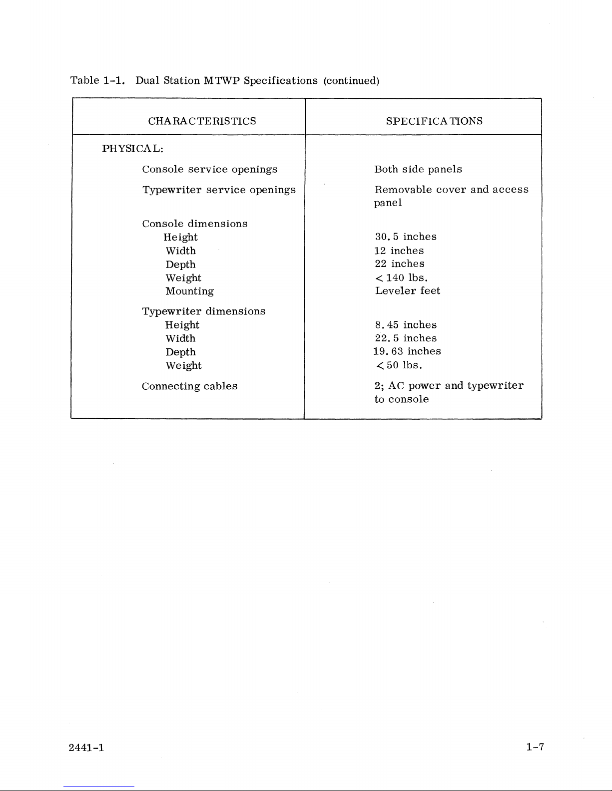
Table
1-1.
Dual
Station
..
CHARACTERISTICS
Copy
capacity
MTWP
Specifications
(continued)
Original
SPECIFICA
plus·
TIONS
five
carbons
Ribbon
Print
MAGNETIC
Read/Write
Search
Start
Stop
Start
Stop
MAGNETIC
Type
Tape
Capacity
type
element
TAPE
TRANSPORTS:
speed
speed
time
time
distance
distance
CASSETTE:
Cartridge
fabric
loaded
or
single-use
Interchangeable
20
ips
(average)
70
ips
(average)
50 ±
10
ms @ 20
50 ±
10
ms @ 20
0.5
±
O.
I-inch @ 20
O.
5 ±
O.
I-inch @ 20
Modified
Computer
300,150
Philips
grade
and
75
(reusable
print
ips
ips
feet
carbon)
wheel
ips
ips
1-6
Storage
Maximum
capacity
search
time
ENVIRONMENTAL:
Temperature
Humidity
range
POWER:
Primary
DC
by
internal
supply
power
voltages
or
range
requirement
supplies)
rewind
(developed
50K, 25K,
acters
51,
26
and
8%
min.
imum
115
+24V ±
+15V
+5.12V
-5V
-9V
-15V
wet
VAC ±
2.
±
O.
±
±
O.
±
O.
±
O.
and
13
to
bulb
10%@
6V
75V
O.
25V
45V
75V
12K
seconds
80%
temp.
05V
char-
max.
15
(max-
80°F)
A
2441-1
Page 17
Table
1-1.
Dual
Station
MTWP
Specifications
(continued)
CHARACTERISTICS
PHYSICAL:
Console
Typewriter
Console
Typewriter
Connecting
service
dimensions
Height
Width
Depth
Weight
Mounting
Height
Width
Depth
Weight
openings
service
dimensions
cables
openings
SPECIFICA
Both
side
Removable
panel
30.5
inches
12
inches
22
inches
<
140
lbs.
Leveler
8.45
inches
22.5
inches
19.63
< 50
2; AC
to
inches
lbs.
power
console
panels
cover
feet
TIONS
and
typewriter
and
access
2441-1
1-7
Page 18

Page 19
2.1
UNPACKING
The
Magnetic
prior
console)
to
shipment.
are
procedures
containers,
If
damage
units
from
any
return
Tape
separately
to
attain
examine
is
evident,
their
packaging.
shipment.
Word
Processor
Individual
packaged
optimum
each
for
contact
INSTALLATION
units
that
into two
system
broken
the
transportation
Original
CHAPTER 2
is
inspected
comprise
containers.
performance.
bands,
packaging
for
crushed
company
material
mechanical
part
of
Perform
Before
walls,
and
the
system
the
removing
or
other
involved
should
be
electrical
(the
following
units
signs
before
retained
operation
typewriter
unpacking
from
of
their
damage.
removing
to
facilitate
and
the
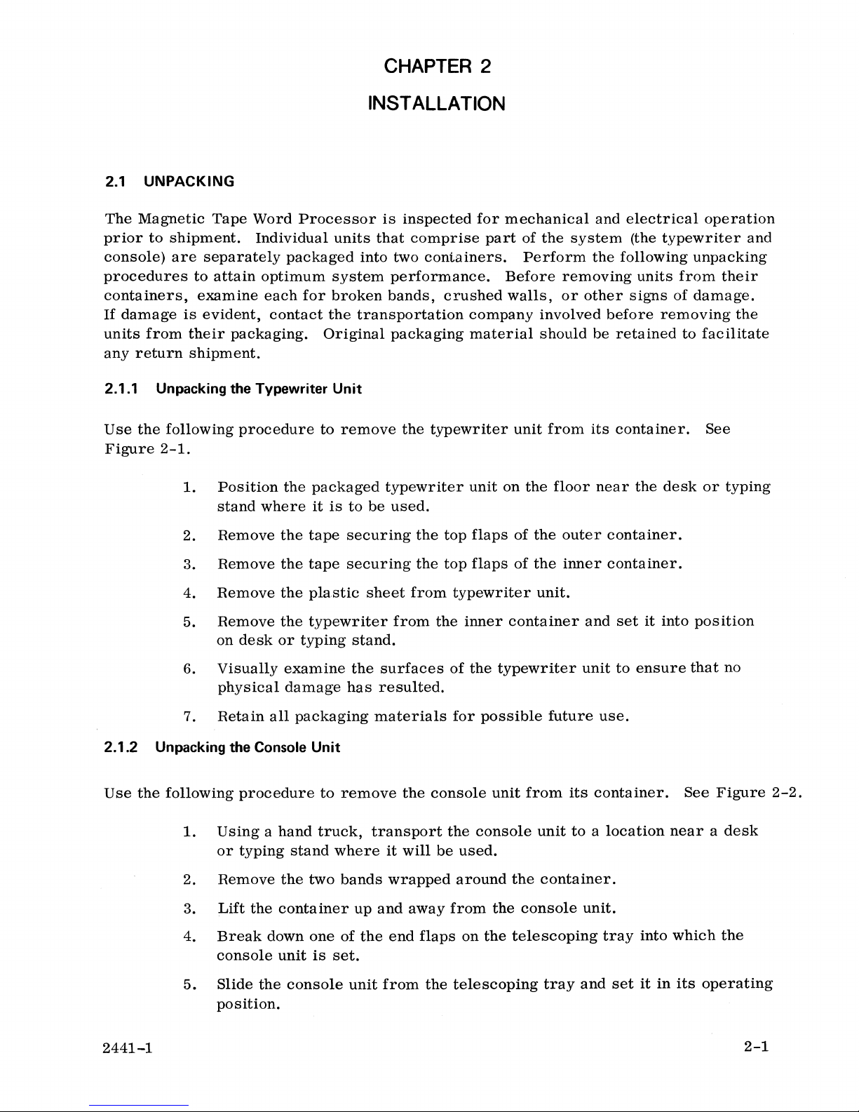
2.1.1 Unpacking
Use
the
following
Figure
2-1.
1.
2. Remove
3.
4.
5.
6.
7.
2.1.2
Use
Unpacking
the
following
the
Typewriter Unit
procedure
Position
stand
where
Remove
Remove
Remove
on
desk
or
Visually
physical
Retain
the
all
Console
procedure
to
the
packaged
it
is
the
tape
the
tape
the
plastic
the
typewriter
typing
examine
damage
packaging
Unit
to
remove
typewriter
to
be
securing
securing
sheet
stand.
the
surfaces
has
resulted.
materials
remove
the
used.
the
the
from
from
the
typewriter
unit
top
flaps
top
flaps
typewriter
the
inner
of
the
for
possible
console
unit
unit
from
on
the
floor
of
the
outer
of
the
inner
unit.
container
typewriter
future
from
its
near
container.
container.
and
unit
use.
its
container.
container.
the
desk
set
it
into
to
ensure
See
or
typing
position
that
no
See
Figure
2-2.
1.
Using a hand
or
typing
2. Remove
3.
Lift
4.
Break
console
5.
Slide
the
the
container
down
unit
the
console
pOSition.
2441-1
truck,
stand
two
one
is
where
bands
up
of
the
set.
unit
transport
it
will
wrapped
and
away
end
flaps
from
the
the
console
be
used.
around
from
the
on
the
telescoping
unit
to a location
the
container.
console
unit.
telescoping
tray
and
tray
set
near a desk
into
which
it
in
its
the
operating
2-1
Page 20
2-2
PLASTIC
SH£E:T
/
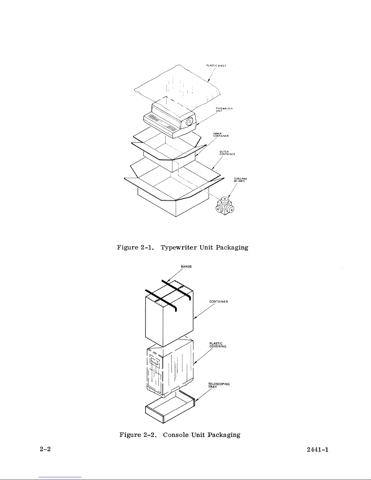
Figure
2-1.
Typewriter
Unit Packaging
BANDS
CONTAINER
TELESCOPING
TRAY
Figure
2-2.
Console
Unit Packaging
2441-1
Page 21
6.
Remove
the
protective
plastic
covering
that
surrounds
the
console
unit.
7. Unwind
S.
Examine
damage
9.
Retain
2.2 SYSTEM INTERCONNECTIONS
Use
the
following
and
2-4.
1.
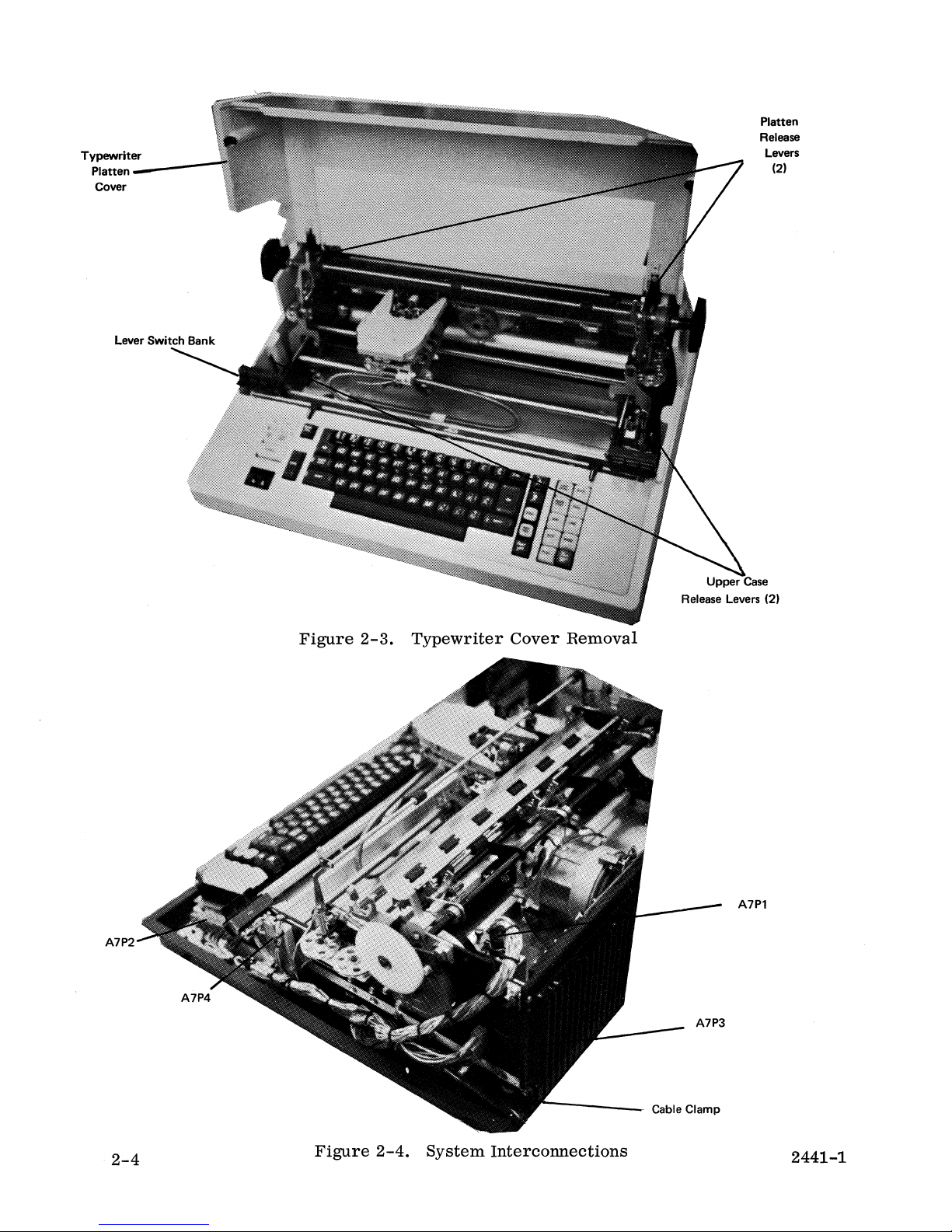
Tilt
2.
Depress
the
the
has
all
packaging
procedure
the
typewriter
the
AC
power
surfaces
resulted.
to
connect
two
platen
writer.
3.
4.
5.
Raise
and
Raise
and
Pull
case
the
left-hand
TAB
CLEAR/SET
the
right-hand
10/12
forward
from
levers.
on
the
the
typewriter.
cord
of
the
materials
the
platen
release
lever
levers.
lever
two
upper
and
interconnection
console
for
two
system
cover
upward
levers
switch
bank
switch
case
unit
possible
components.
to
and
that
bank
that
release
to
ensure
future
expose
lift
the
supports
supports
levers
cable.
that
use.
the
platen
and
no
physical
See
Figures
platen.
from
the
the
MARG
the
remove
LEFT/RIGHT
SINGLE/DOUBLE
the
2-3
type-
upper
6.
7.
S.
9.
10.
11.
12.
13.
Remove
Lay
in
Locate
NOTE:
A7P1
A7P2
A7P3
A7P4
Place
the
removed
Examine
broken
Replace
place.
Lower
Lower
the
two
screws
the
typewriter-to-console
and
mate
the
four
Alternately,
A
7P1,
A 7P3
34-pin
56-pin
14-pin
14-pin
cable
in
the
connections,
the
both
the
step
interior
upper
lever
platen
clamp
6.
of
loose
cover
switch
cover.
that
secure
following
tighten
and A 7P4
back
into
the
typewriter
screws,
and
then
banks
the
cable
innerconnection
typewriter-to-console
both
screws
in
place.
Printer
Keyboard
Power
Lever
place
or
the
platen
into
place.
to
Interface
Interface
Connector
Switch
and
to
Interface
secure
ensure
debris
by
clamp
cable.
secure
Connector
Edge
using
there
located
snapping
to
lower
connectors.
Connector
Connector
the
are
in
the
them
case.
two
screws
no
loose
typewriter.
back
or
into
14.
Remove
lower
Lift
it
the
edge
up
2441-1
right-hand
of
the
and
away
panel
from
access
and
pulling
the
panel
frame.
from
it
away
the
from
console
the
by
frame
grasping
structure.
the
2-3
Page 22
Typewriter
-----
Platten
Cover
Platten
Release
Levers
(2)
A7P2
Figure
2-3.
Typewriter
Cover
Removal
A7Pl
A7P3
2-4
Figure
2-4.
System
------
Interconnections
Cable Clamp
2441-1
Page 23
15.
16.
17.
Examine
are
no
the
console.
Verify
that
seated
PWA in
Verify
the
loose
in
its
the
that
interior
or
broken
each
printed
respective
card
cage
the
following
of
the
console
connections,
wiring
socket
is
listed
internal
from
loose
assembly
of
the
card
in
Chapter 4 of
connections
this
side
screws,
(PWA)
cage.
are
is
this
to
ensure
or
debris
properly
The
location
manual.
secure:
that
there
located
located
of
each
in
and
Printer
Keyboard
R/W
Read/Write
RO
Read
NOTE:
18.
Examine
19.
Release
sensors
2.3 PREOPERATIONAL CHECKOUT
Once
the
be
checked
diagnostic
system
for
checkout.
components
proper
Interface
Interface
Tape
Control
(R/W
Tape
Control
Only (RO
Leave
to
each
the
the
facilitate
tape
door
to
with a lint-free
have
operation.
2.3.1 Power Supply Voltage Checkout
(PWA 1)
(PWA
(PWA 17)
J2)
(PWA 20)
J2)
right-hand
the
system
transport
each
tape
wiper
been
unpacked,
This
involves a power
3)
to
Tape
to
Tape
side
diagnostic
for
physical
transport
dampened
inspected,
access
and
with
panel
checkout.
damage.
wipe
90%
and
supply
off
off
the
heads
isopropyl
connected,
voltage
and
EOT
alcohol.
they
may
and a system
Use
the
voltages.
2441-1
following
See
Figure
1.
Remove
lower
Lift
2.
Lower
screws.
3.
Examine
loose
4.
Verify
circuit
5.
Connect
6.
Set
procedure
2-5.
the
edge
it
up
and
the
power
the
or
broken
that
breaker
the
CB1
to
ON.
to
initially
left-hand
of
the
panel
away
supply
interior
connections,
the
two
(CB1)
power
power
side
access
and
pulling
from
the
frame.
interconnect
of
the
console
15A
fuses
and
POWER
cord
to a 115 VAC, 60
up
loose
(F1
and
the
system
panel
it
away
panel
from
screws,
F2)
switch
from
from
by
this
are
are
Hz
or
to
the
console
the
loosening
side
or
debris
installed
set
to
power
verify
frame
to
ensure
in
and
the
source.
power
by
grasping
structure.
the
two
there
the
console.
both
OFF
supply
securing
are
the
main
pOSition.
the
no
2-5
Page 24
DC Regulator
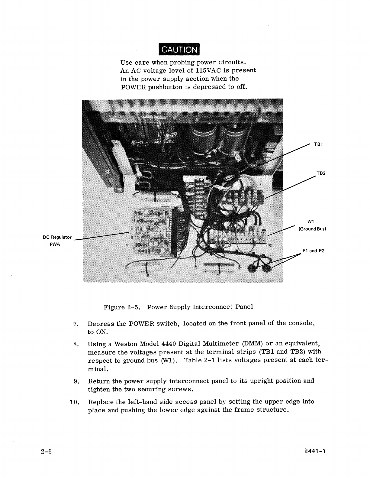
PWA
Use
care
An
AC
in
the
power
POWER
CAUTION
when
voltage
supply
pushbutton
probing
level
of
section
is
power
circuits.
115VAC
when
depressed
is
present
the
to
off.
TB2
W1
(Ground Bus)
Figure
7.
Depress
to
ON.
8.
Using a Weston
measure
respect
the
the
to
ground
minal.
9.
10.
Return
tighten
Replace
place
the
the
and
the
pushing
2-6
2-5.
POWER
Model
voltages
power
two
securing
left-hand
Power
switch,
4440
present
bus
(WI),
supply
side
the
lower
Supply
Interconnect
located
Digital
at
the
Table
interconnect
screws.
access
edge
panel
against
on
the
front
Multimeter
terminal
2-1
lists
panel
by
to
setting
the
Panel
panel
(DMM)
strips
voltages
its
upright
the
frame
structure.
of
or
(TB1
present
upper
the
console,
an
equivalent,
and
TB2)
at
position
edge
with
each
and
into
2441-1
ter-
Page 25
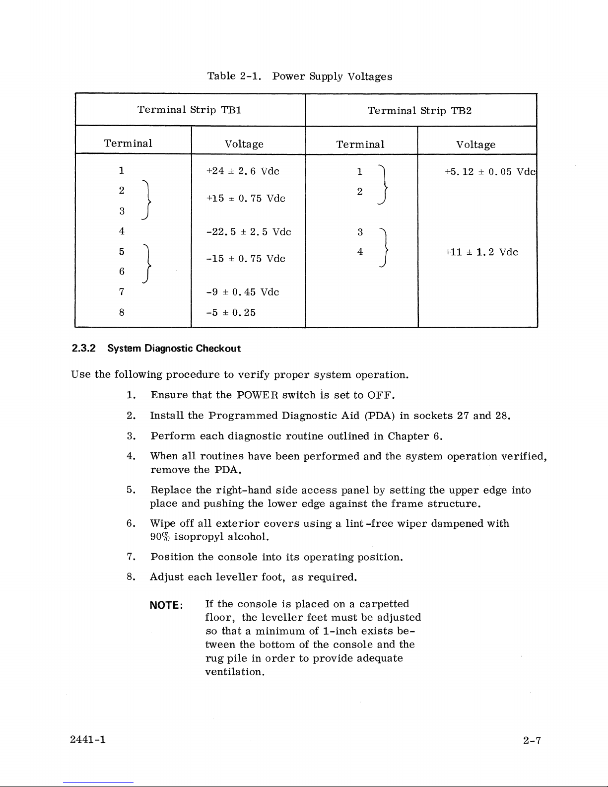
Table
2-1.
Power
Supply
Voltages
Terminal
Terminal
1
2
)
3
4
5
}
6
7
8
2.3.2 System Diagnostic Checkout
Use
the
following
1.
Ensure
Strip
+24 ±
+15
-22.5 ± 2.5
-15 ± 0.75
-9
-5
procedure
that
TB1
Voltage
:!:
±0.45
±0.25
to
the
2.6
Vdc
0.75
Vdc
Vdc
Vdc
Vdc
verify
POWER
proper
switch
Terminal
system
is
set
Terminal
1
2
}
3
4
}
operation.
to
OFF.
Strip
TB2
Voltage
+5.12 ± 0.05
+11 ±
1.
Vdc
2 Vdc
2.
3.
4.
5.
6.
7.
8.
Install
Perform
When
remove
Replace
place
Wipe
90%
Position
Adjust
NOTE:
all
and
off
isopropyl
the
Programmed
each
routines
the
PDA.
the
right-hand
pushing
all
exterior
the
console
each
leveller
If
the
floor,
so
that a minimum
tween
rug
ventila
diagnostic
have
the
lower
covers
alcohol.
into
foot,
console
the
leveller
the
bottom
pile
in
order
tion.
Diagnostic
routine
been
performed
side
access
edge
using a lint
its
operating
as
required.
is
placed
feet
of
of
the
to
provide
Aid
(PDA)
outlined
panel
against
on a carpetted
must
1-inch
console
in
and
by
the
-free
position.
be
adjusted
exists
and
adequate
in
sockets
Chapter
the
system
setting
frame
wiper
be-
the
27
6.
operation
the
upper
structure.
dampened
and
edge
28.
verified,
into
with
2441-1
2-7
Page 26

Page 27
CHAPTER 3
OPERATION
3.1
KEYS, CONTROLS, INDICATORS AND ALARMS
Each
key
on
the
understanding
•
• Mode
•
•
In
each
classification, a key
illustration
The
controls
a
description
is
keyboard
as
to
Basic
Action
Encoded
provided
and
indicators
of
each
their
has
functions:
Operation
Keys
Keys
Function
is
for
each
located
system
been
Keys
Keys
first
group
alarm
classified
identified,
to
on
the
is
presented.
and
assist
Console
presented
and
then
in
the
are
as
its
function
location
then
identified
follows
is
of
each
to
provide a better
defined.
discussed
and
defined
An
key.
and
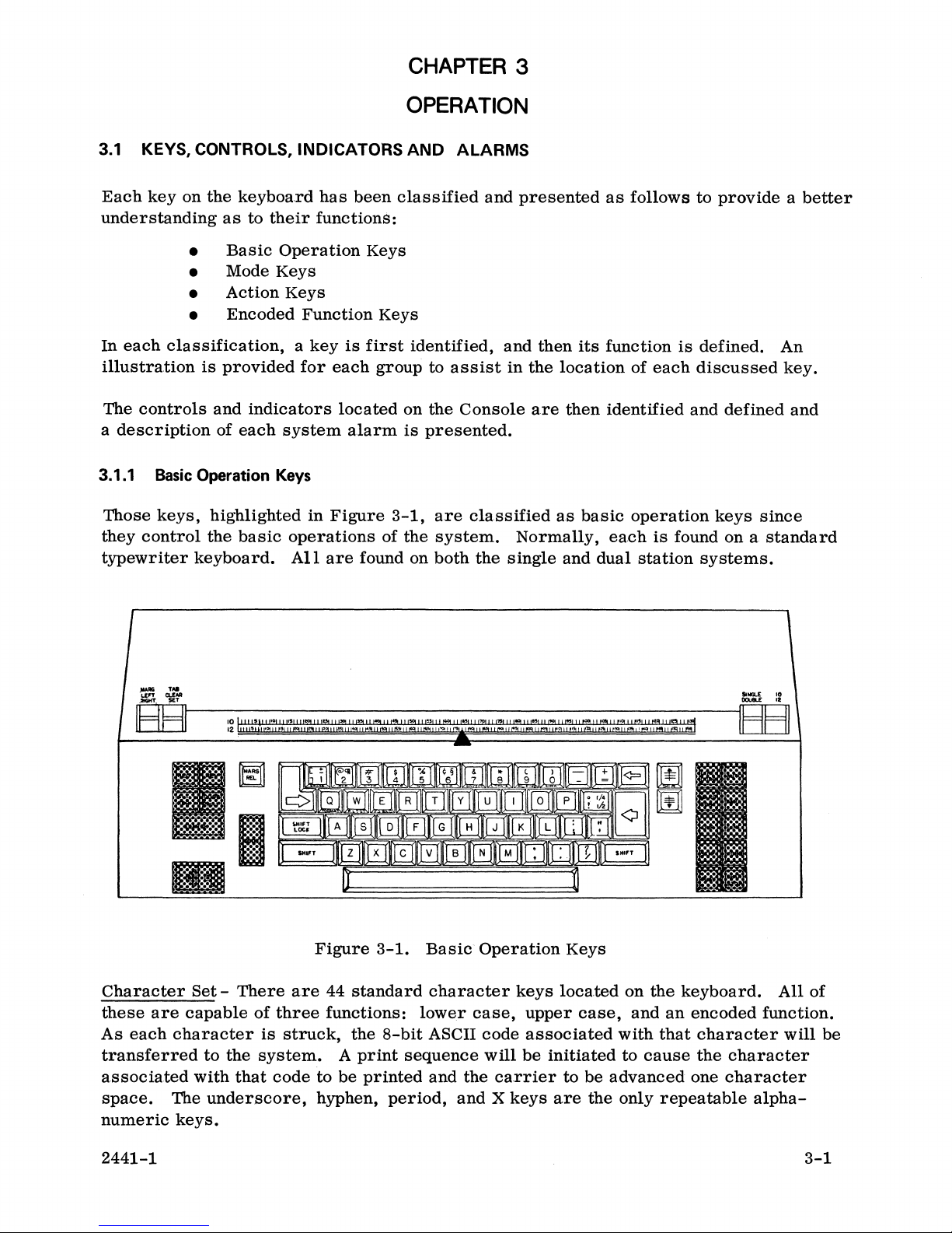
3.1.1
Those
they
Basic
keys,
control
typewriter
Operation
highlighted
the
basic
keyboard.
Keys
in
Figure
operations
All
are
3-1,
of
the
found on
are
classified
system.
both
the
as
Normally,
single
and
basic
each
dual
operation
is
found on a
station
keys
since
systems.
Sutal
.. ! 10
DCIUILE
IBBI
standard
..
Figure
Character
these
As
each
transferred
associated
space.
numeric
Set -There
are
capable
character
with
The
keys.
of
three
is
struck,
to
the
system.
that
code
underscore,
are
to
hyphen,
2441-1
3-1.
44
standard
functions:
the
8-bit
A
print
be
printed
period,
Basic
character
lower
ASCII
sequence
and
the
and X keys
Operation
keys
case,
code
will
upper
associated
be
carrier
Keys
located
case,
initiated
to
be
are
the
on
the
and
an
with
that
to
cause
advanced
only
repeatable
keyboard.
encoded
character
the
character
one
character
All
of
function.
will
alpha-
3-1
be
Page 28
Space
to
Bar
right
seconds,
Bar
remains
- The Space
one
character
the
carrier
depressed
Bar,
space
will
or
when
for
each
continue
until
the
depressed,
depression.
to
move
from
right-hand
will
left
stop
cause
If
held
to
is
reached.
the
for
right
carrier
greater
for
so
to
than
long
move
500
as
the
from
milli-
Space
left
Shift - The
shift
of
case
8-bit
left-
the
keyboard
ASCII
or
right-hand
(no
code
associated
Shift Lock - The Shift Lock
position.
Carrier
move
vertical
Lever.
vertical
When
carrier
referenced
The
lock
Return-
to
the
left-hand
index
If
held
indexing
depressed
return"
in
paragraph
will
be
The
Carrier
margin
operations
for
greater
for
as
together
will
be
encoded
tion.
TAB
CLEAR/SET
The
lever,
carrier
hand
margin
left-hand
when
to
be
margin
pOSition.
Lever -This
placed
stored
or
to
by the
There
the
printer
key
mechanically
released
and
specified
than
long
as
with
3.2
of
down
(SE
system.
must
left
Shift
key,
movement).
with
each
when the Shift
Return
the
key,
paper
by the
500
milliseconds,
the
Carrier
the
CODE key
onto
the
this
manual
lever
T)
is
will
A
be
at
of
the
right-hand
when
setting
tape.
used
cause
tab
least
held
As
each
struck
locks
only
key
when
depressed,
feed
to
of
Return
during
Refer
for
details
to
electronically
the
cannot
one
margin.
depressed,
character
character
the
left-hand
is
depressed.
execute
the
SINGLE/DOUBLE Line Space
the
paper
key
remains
the
Record
to
the
on
code
for
be
set
directly
character
will
is
transferred
will
the
number
feed
mode, a "required
Operating
the
use
set
the
present
space
cause
is
struck,
Shift
key
cause
the
of
will
continue
depressed.
Insutructions
of
this
encoded
or
clear
position
at
the
left-
to
the
an
electronic
the
upper
to
the
in the
upper
carrier
forward
forward
tab
locations.
of
or
right-
right
of
system.
ca
to
func-
the
the
se
POSitioning
stored
will
be
The
lever,
carrier
be
set
the
location.
cleared.
when
pOSition
for
playback.
NOTE:
carrier
When
This
placed
to
Tab -Depression
tion
to
the
first
set
position;
When
will
graph
depressed
be
encoded
3.2
of
onto
this
together
manual
MARGLEFT/RIGHT
hand
sent
margin
position
pOSition. The
of
the
to a
tab
placed
may
be done
down (SET)
be
encoded
Since
tronic
ical
be
cleared
cept
of
the
Tab
tab
location
with
the
tape
for
Lever -This
lever
carrier
to
location
up (CLEAR)
at
during
onto
the
the
storing
function
tabs),
all
when
for
those
key
will
provided
the
CODE
..
Refer
details
to
on
lever
when
be
stored
and
together
any
carrier
the
tape.
of tab
(there
tab
locations
the
encoded
cause
that
key,
the
the
use
is
placed
by
the
placing
the
with
position.
Record
In
this
locations
are
noac'tual
power
is
onto
the
carrier
the
carrier
during
Operating
of
this
used
to
electronically
up
(LEFT)
system.
lever
the
CODE
mo:.e,
way,
tab
is
will
an
mechan-
will
automatically
turned
tape.
to
move
is
not
the
Record
Instructions
encoded
will
With
up
(CLEAR)
key,
cause
locations
will
all
the
will
stored
elec-
on,
ex-
from
at
its
the
right-hand
present
mode, a "required
referenced
function.
set
the
left-and
cause
the
the
carrier
code
repositioned
clear
the
tabs
code
for
the
automatically
loca-
stop
tab"
in
para-
right-
for
the
pre-
3-2
2441-1
Page 29
for
the
margin
The
lever,
the
left-
left-
and
right-hand
position.
NOTE:
when
and
right-hand
right-hand
margin,
used
margins
the
The
reach
system
that
right-hand
during
margin
lever
keyboard
the
right-hand
buzzer
five
spaces
the
Record
positions
will
automatically
can
be
does
will
remain
margin
mode,
to
placed
not
down (RIGH
lock
margin.
sound
to
before
is
encountered.
will
be
encoded
be
set
when
The
indicate
the
cause
onto
for
T)
to
you
the
codes
the
tape.
playback.
store
the
associated
In
this
right-hand
with
way,
the
During
position
stored
margin
with
tions
MARG
the
the
initial
and
then
and
in a
positions
8-1/2" x 11"
or
setting
NOTE:
REL
- The
present
left-hand
Backspace -The
right
to
left
one
seconds,
key
remains
When
space"
paragraph
the
carrier
depressed
depressed
will
be
3.2
encoded
of
power
spaced
similar
(10/70
paper.
the
desired
margin
margin.
Backspace
character
will
together
this
manual
on
sequence,
to a
standard
the
left-hand
manner a right-hand
for
The
margin
Since
is
an
actual
will
power
encoded
release
key,
space
continue
or
until
with
onto
the
10-pitch
operator
the
electronic
automatically
the
for
or
12/84
then
positions
storing
mechanical
is
turned
onto
tape.
key,
when
when
for
the
tape.
each
to
move
left-hand
CODE
details
depressed,
key,
Refer
on
function
on
carrier
is
margin
margin
for
12-pitch)
has
the
as
previously
of
margin
(there
stops),
be
cleared
except
depressed,
will
depression.
from
right
margin
during
to
the
Opera
the
use
positioned
position.
position
option
positions
are
all
margins
when
for
those
permits
cause
If
held
to
left
is
reached.
the
Record
ting
of
this
encoded
to
the
left
The
is
stored.
are
typical
of
using
these
described.
no
the
the
operator
the
carrier
for
greater
for
as
long
mode, a "required
Instructions
function.
most
position
These
settings
standard
to
move
than
as
the
referenced
is
stored
for
use
posi-
to
bypass
from
500
milli-
Backspace
back-
in
Forward
to
execute
the
key
During
read
vertical
Reverse
to
execute
the
paper
key
Index
paper
remains
the
during
index
Index
remains
(£)
forward
feed
will
depressed.
Record
playback,
operation.
(i=)
reverse
feed
will
depressed.
- The
vertical
continue
mode,
the
-
The
vertical
continue
2441-1
Forward
index
forward
the
Forward
paper
Reverse
index
reverse
Index
operations.
vertical
Index
feed
will
Index
key,
operations.
vertical
key,
when
If
held
depressed,
indexing
code
will
automatically
when
depressed,
If
held
indexing
for
for
be
execute
for
for
will
greater
as
long
recorded
each
will
greater
as
long
cause
than
as
the
onto
cause
than
as
the
the
500
milliseconds,
Forward
the
tape.
recorded
the
500
milliseconds,
Reverse
paper
forward
paper
Index
feed
Index
When
feed
3-3
Page 30
During
read
vertical
the
Record
during
index
mode,
playback,
operation.
the
the
paper
Reverse
feed
Index
will
code
automatically
will
be
recorded
execute
onto
each
the
tape.
recorded
When
reverse
SINGLE/DOUBLE
spacing
10/12
ten
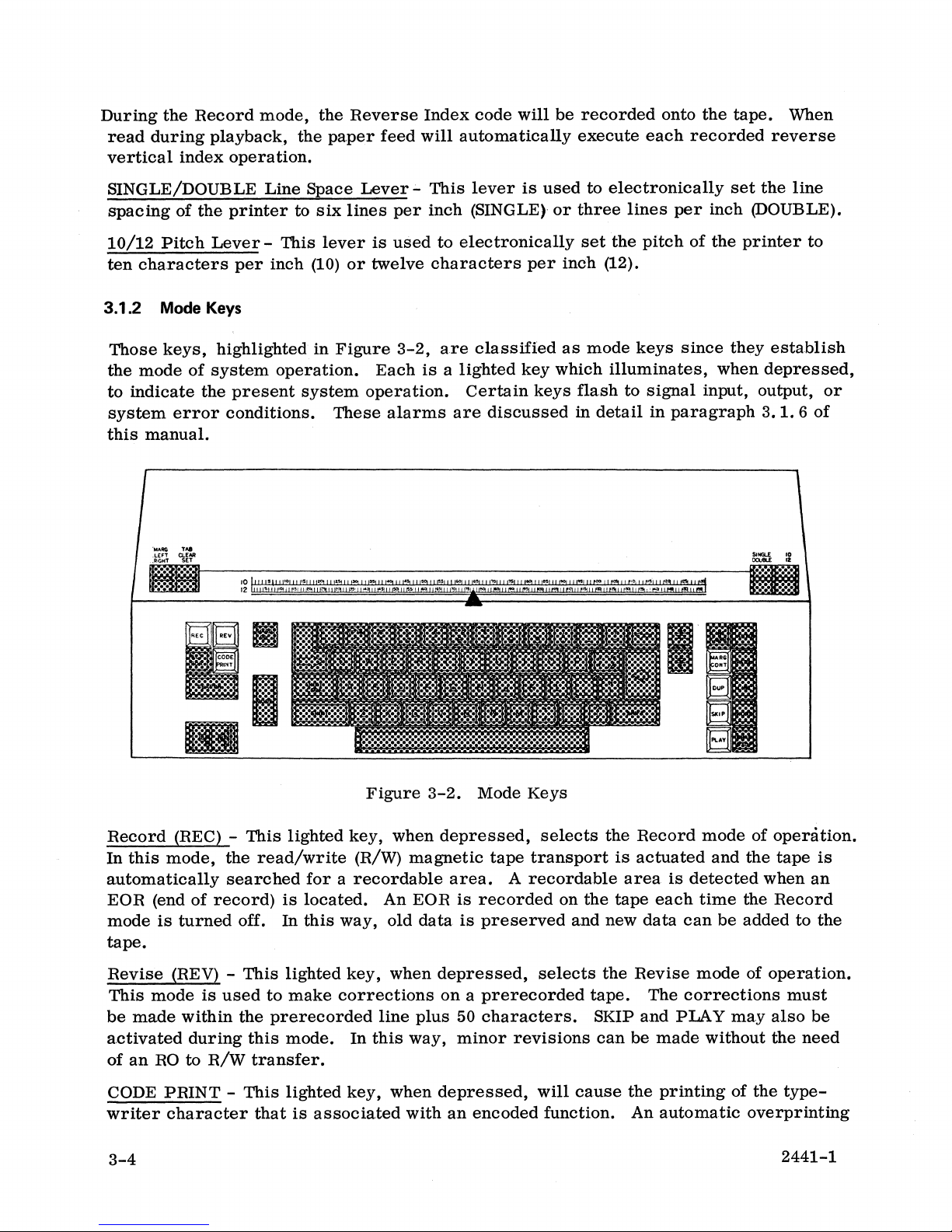
3.1.2
Those
the
to
system
this
of
Pitch
characters
Mode
keys,
mode
of
indicate
error
manual.
the
printer
Lever -This
per
Keys
highlighted
system
the
present
conditions.
Line
Space
to
six
lever
inch
(10)
in
operation.
system
Lever -This
lines
per
is
used
or
twelve
Figure
3-2,
Each
operation.
These
alarms
lever
inch
(SINGLE)-
to
electronically
characters
are
classified
is a lighted
Certain
are
discussed
is
used
per
key
keys
to
or
three
set
inch
as
mode
which
flash
in
electronically
lines
per
the
pitch
(12).
keys
since
illuminates,
to
signal
detail
in
paragraph
set
the
line
inch (DOUBLE).
of
the
printer
they
establish
when
depressed,
input, output,
3.
1.
6
to
or
of
Record
In
this
automatically
EOR (end
mode
(REC) -
mode,
of
is
turned
This
the
read/write
searched
record)
off.
lighted
for a recordable
is
located.
In
this
tape.
Revise
This
be
activated
of
CODE
writer
(REV) -
mode
made
within
during
an
RO
to
PRINT -This
character
is
used
R/W
This
lighted
to
make
the
prerecorded
this
mode.
transfer.
lighted
that
is
associated
3-4
Figure
key,
when
(R/W)
way,
key,
magnetic
An
EOR
old
data
when
corrections
line
plus
In
this
way,
key,
when
with
3-2.
Mode
Keys
depressed,
tape
transport
area.
is
is
depressed,
A
recordable
recorded
preserved
selects
on a prerecorded
50
characters.
minor
depressed,
an
revisions
will
encoded
selects
the
is
Record
actuated
area
on
the
tape
and
new
the
Revise
tape.
SKIP
and
can
be
cause
the
function. An
is
detected
each
data
can
mode
The
corrections
PLAY
made
printing
automatic
mode
and
time
the
be
added
may
without
of
of
operation.
the
tape
is
when
an
Record
to
the
of
operation.
must
also
be
the
need
the
type-
overprinting
2441-1
Page 31

of
this
character
not a regular
tion
will
also
the
encoded
with a slash
typed
be
functions
character.
printed,
they
(/)
Those
but
not
represent.
will
follow to
numeric
slashed.
indicate
codes
Table
3-1
that
that
accompany
lists
this
those
is
an
encoded
an
slashed
function,
encoded
characters
func-
and
When
will
will
depressed
automatically
occur
together
print
as
specified,
CODE ENCODED FUNC TION KEY
i
$
I:
~
¢
'I
g
or
1
~
with
the CODE
out
on
the
paper.
but
no
slashed
Table
3-1.
Reference
Stop
Transfer
Switch
Search
Switch and
SINGLE/DOUBLE
First
Line
Encoded
Stop
Search
Find
key,
all
If
CODE
character
Function
Line
prerecorded
PRINT
will
print.
Codes
Space L SPACE
is
margin
not
on, the
and
REF
STOP
TSTOP
SW
SCH
SW/SCH
FL
FIND
tab
settings
encoded
function
fQ
VI
t
Margin
will
zone.
Instructions
mode
Duplicate
cause a high
R/W
the
licated.
all
address
next
Depressing
Control
automatically
This
and
the
(PUP) -
without
AUTO
data
key
If
from
will
sequential
f5
(MARG CONT) -
cause
zone
may
referenced
zone
adjustment
This
speed
printing
a
block
the
be
the
transfer
is
depressed,
address
present
duplicated.
block
PARA, LINE, WORD,
Track
Format
First
Page
the
be
adjusted
in
paragraph
lighted
on
paper.
location
address
Link LINK
Line
End
This
right-hand
from
technique.
key
(dual
of
data
(1000
If
a 00
all
data
is
set
into
up
When
and
the
stop
FORMAT
Set
(line count) PG END
lighted
margin
0 to 7
3.2
is
from
the
to
but
block
without
or
key,
when
to
readjust
character
of
this
manual
station
characters
set
the
thumbwheels
CHAR/STOP
systems
into the
present
not
including
address
duplicating
depressed
spaces.
for
only),
per
second)
block
location
and
that
is
located,
key
within a five
details
address
the
data
that
will
FL
during
Refer
when
from
to
an
AUTO
specified
the
block
then
SET
character
to
on
the
depressed,
the
thumbwheels
EOR
will
key
R/W
will
of
information.
cause
the
Play
the
Operating
use
of
RO
to
be
is
depressed,
by
the
write
only
that
mode,
space
this
will
the
and
dup-
block
the
2441-1
3-5
Page 32

selected
which
portion
is
lower
duplication
When
key
the
will
extinguish.
of
than
of
data
will
duplication
the
data
that
for
only
is
completed,
to
be
duplicated.
the
present
terminate
the
location,
after
all
system
If
the
no
selected
buzzer
thumbwheels
duplication
conditions
will
sound
are
will
and
set
take
have
the
to a
place.
been
lighted
block
address
The
fulfilled.
action
SKIP coded
key
and
PIA
mode,
This
functions,
operates
CHAR/STOP.
Y -
This
the
R/W
commanded
The
PIA Y key,
will
cause
data
paper.
When
be
for
3.1.3 Action
Those
action,
used
read
this
from
operation
keys,
when
lighted
to
in
conjunction
lighted
magnetic
by
the
depression
when
to
be
in
conjunction
the
RO
to function.
Keys
highlighted
depressed.
key,
be
read
key,
used
read
and
when
without
with
when
tape
in
from
with
printed
in
Figure
depressed,
printing
the
action
depressed,
transport
of
an
action
conjunction
the
RO
and
the
ALT
RDR
on
paper.
3-3,
are
will
or
keys,
selects
is
activated
key.
with
written
key
The
classified
cause
recorded
performing
i.
e.,
AUTO, PARA, LINE, WORD,
the
and
the
REC
into
(dual
station
system
as
Play
data
key
the
must
action
data,
the
encoded
mode
is
(dual
R/W,
systems
not
of
read
station
as
be
keys
including
function.
operation.
and
printed
systems
well
as
printed
only),
in
the
Record
since
they
any
data
cause
en-
This
In
this
as
only)
on
will
mode
an
SEARCH loaded
tape
responds
lighted
until
3-6
This
transport
to
the
the
lighted
key,
and
particular
block
address
Figure
when
3-3.
depressed
automatically
block
address
is
located
Action
search
set
into
and
Keys
during
the
the
then
it
the
Play
mode,
tape
for a block
thumbwheels.
will
extinguish.
will
actuate
address
The
key
SING...!
10
D<lUIU "
the
which
will
2441-1
cor-
remain
Page 33

When
RO
to
used
R/W
in
conjunction
transfer,
the
with
RO
the
tape
ALT
will
RDR
be
searched
key
(dual
for
station
the
block
systems
address.
only)
during
an
Block
address
into
ALT
the
the
cause
iated
are
Address
ranging
the
tape,
RDR - The
Play
mode,
R/W
(standard
the
reading
with
the
located
Thumbwheels -These
from
particular
alternate
will
selected
on
the
LINE CORR - The
cause
the
will
not
rewind
line.
over
AUTO modes,
information.
that
line
carrier
not
returned
appear
transferred
the
tape
The
tape,
any
portion
This
will
cause
of
on the
from
and
in
of
lighted
These
00 to 99. Since
segments
reader
cause
reader
to
be
the
in the
returned
reader,
console.
line
correct
information
to
the
left-hand
tape,
the
buffer
reverse
this
case,
the
existing
key,
when
the
system
blocks
are
can
key
reading
Play
to
will
key,
presently
nor
will
onto
vertical
will
be
information.
depressed
to
play
separated
thumbwheels
block
addresses
easily
(dual
station
of
information
mode)
the
light
when
to
R/W.
when
depressed
being
margin
the
the
index
erased
position
tape
tape.
the
and
during
and
print,
by
are
used
are
be
searched
systems
from
the
RO. A
The
Active
the
reader
during
stored
in the
without
be
erased
Each
paper
or
subsequent
feed
rerecorded
the
Play,
skip,
or
prerecorded,
to
set a two-digit
sequentially
or
located.
only),
the
when
tape
subsequent
READ
is
Station
activated.
the
Record
buffer
to
prerecorded
depressed
to
be
switched
depression
Indicator
These
mode,
be
cleared,
indexing. The
rewound,
since
depression
to
the
beginning
as
the
operator
Revise,
Skip,
duplicate a single
sequential
block
block
will
assoc-
indicators
will
and
information
that
line
will
merely
of
each
previous
retypes
or
Duplicate
block
of
addresses.
during
from
was
During
by
the
PARA modes,
of
operation
the
block
thumbwheels
This
will
information.
or a required
LINE modes,
This
will
information.
line
and
stops
WORD modes,
including
next
end
will
word.
of a
This
all
word
CHAR/STOPmodes,
will
played
will
cause a single
and
printed,
in
the
address,
lighted
cause
carrier
lighted
cause
A
carrier
the
lighted
cause
set
are
set
key,
the
Two
consecutive
return
key,
the
operation.
key,
the
punctuation,
A
space
and
This
or a carrier
stops
key,
immediately
character,
skipped,
Duplicate
into
to
00,
when
system
will
when
system
return,
when
system
spaces,
the
operation.
when
stop
or
mode,
the
block
the
remainder
depressed
to
play
carrier
signal
depressed
to
play
all
data
address
during
and
print,
returns, a carrier
the
end
during
and
print,
whether a required
depressed
to
play
tabs,
return,
depressed
the
respective
punctuation,
during
and
print,
and
carrier
whether a required
during
operation.
space,
duplicated.
up
to
but
thumbwheels,
of
the
tape
the
Play,
skip,
of a
the
skip,
or
paragraph
Play,
or
one
the
Play,
skip,
or
returns
the
Play,
tab,
carrier
not
will
Revise,
including
will
be
duplicated.
that
be
duplicated.
Skip,
duplicate a single
return
Revise,
and a required
and
stop
Skip,
duplicate a single
or
not,
signals
Revise,
Skip,
duplicate a single
that
follow
one
or
not,
Revise,
Each
Skip
subsequent
return,
data
or
Duplicate
paragraph
the
operation.
or
Duplicate
line
the
end
or
Duplicate
word
it
up
to
signals
or
Duplicate
depression
etc.
to
specified
If
tab,
of
of
a
the
the
be
2441-1
3-7
Page 34

3.1.4
Encoded
Function
Keys
Those
they
playback.
depressed.
keys,
encode
highlighted
and
record
These
codes
II
8
in
Figure
onto
will
Figure
the
not
3-4,
tape
print
3-4.
are
classified
those
codes
on
the
Encoded
paper
Function
as
which
unless
encoded
control
the
CODE
Keys
function
system
PRINT
keys
since
function~
key
during
is
CODE during
code
functions.
the
for a particular
This
key,
Record
KEY
REF
STOP
TSTOP
SW
SCH
SW/SCH
L SPACE
FL
FIND
LINK
FORMAT
FLSET
PGEND
when
mode,
system
held
will
Table
depressed
cause
function.
3-2.
CODE
the
Encoded
i
~
"
~
~
t
~
or
~
f1
f4
W
t
together
system
Table
f
with
anyone
to
encode
3-2
lists
Function
ENCODED FUNC
Reference
Stop
Transfer
Switch
Search
Switch
SINGLE/DOUBLE
First
Track
Format
First
Page
and
those
Keys
Stop
and
Line
Link
Line
End
(line count)
keys
Search
Find
Set
of
the
record
that
Line
following
onto
the
will
encode
nON
Space
keys
tape
the
3-8
2441-1
Page 35

The
following
during
Refer
details
the
to
on
Record
the
Operating
the
keys
use
and
levers,
mode,
Instructions
of
each.
will
when
encode
referenced
depressed
and
record a required
or
in
set
together
paragraph
with
function
3.2
of
the
onto
this
CODE
the
tape.
manual
key
for
ERASE -
into
the
passed.
ning
rather
REF
(~')
mode,
address
by
1.
These
on
the
tape.
STOP
($) -
mode,
during
operator
etc.
T
STOP
mode,
read
during
The
difference
mation
tape
and
This
key,
Record
In
this
than
-
This
will
encode
onto
the
block
This
will
encode
playback,
to
type
(~)
-
This
will
encode
playback,
in
the
Record
the
stop
Space
Carrier
Bar
Return
Tab
when
depressed
Mode (REC
key
way, a prerecorded
from
key,
key,
between
an
when
and
record a reference
tape.
addresses
when
and
record a stop
will
automatically
in
additional
key,
and
record a transfer
will
mode
code
will
EOR.
depressed
The
block
are
depressed
information
when
depressed
cause a function
the
two
from
not.
together
lights)
address
used
stop
is
that
the
Backspace
Forward
and
tape
can
together
code
counter
to
separate
together
code
($) onto
both
not
together
stop
this
RO to
with
the
automatic
be
with
with
printing
found
code
which
code
the
R/W,
Index
the
erased
the
(2)
together
in
particular
the
the
on
with
(~)
is
identical
must
CODE
search
and
CODE
the
R/W
CODE
tape.
and
the
the
onto
be
used
since
Reverse
Hyphen
key,
will
put
for
an
EOR
rerecorded
key
during
with a sequential
will
also
segments
key
during
This
code,
playback
tape,
CODE
the
when
it
will
such
key
tape.
to
that
transfer
to
permit
as a name,
during
This
of
transferring
Index
the
system
will
from
the
its
Record
block
be
incremented
of
information
the
Record
when
read
the
the
code,
the
stop
onto
be
by-
begin-
date,
Record
when
code.
infor-
the
new
SW
(~)
mode,
during
enables
two
different
SCH
(is)
mode,
must
also
address,
the
prerecorded
played
The
direction
address
actuated
when
SW
mode,
the
/SCH
will
2441-1
-
This
key,
will
encode
playback,
the
operator
tapes.
-
This
will
encode
be
entered
when
back
irrespective
of
as
compared
when
the
tape
is
(1) -
This
encode
will
key,
read
block
the
at
when
and
and
depressed
record a switch
cause
to
when
the
automatically
depressed
record a search
from
during
the
playback,
address.
of
their
search
to
tape
its
key,
and
record a switch
the
is
end
when
(forward
current
at
its
or
together
system
together
keyboard
In
this
chronological
or
block
beginning
at
an
EOR.
depressed
with
code
to
switch
combine
code
at
this
will
cause
way,
reverse)
address.
and
together
and
search
the
(~)
onto
from
and
print
with
the
(is)
onto
time.
the
particular
order
is
determined
an
automatic
with
code
CODE
the
tape.
one
information
CODE
the
tape.
The
system
segments
on
the
An
automatic
the
(1)
key
during
This
reader
key
during
A
code
together
to
automatically
tape.
by
reverse
CODE
onto
key
the
the
code,
to
the
other.
prerecorded
the
two-digit
with
of
information
the
deSignated
forward
search
during
tape.
Record
when
Record
block
the
search
search
is
actuated
the
A
two-digit
read
This
on
address
block
to
can
be
block
is
Record
3-9
Page 36

block
with
ally
block
address
the
block
switch
address.
prerecorded
must
address,
from
on
one
In
two
this
also
be
when
reader
way,
different
entered
read
to
the
an
operator
tapes
from
during
other
the
playback,
and
can
irrespective
keyboard
at
will
search
the
active
automatically
of
their
chronological
this
cause
combine
time.
the
reader
The
system
for
and
print
order
code
together
to
automatic-
the
prerecorded
information
on
the
tapes.
L SPACE ($
Record
double
code
ally
Space
FL
mode,
mode,
space)
for
select
Lever.
FIND
will
the
playback,
forward
counter
LINK
mode,
added
ally
in
that
SCR -
will
special
Since a
return,
such
vertical
at
(~)
-
will
as
the
skipped
line
This
cause
carrier
special
its
as
typing a mailing
or
will
for
setting
the
prescribed
(~)
-
This
encode
this
code
that
time.
This
encode
first
during
which
key,
the
carrier
carrier
function
f)
-
This
encode
the
present
of
the
key,
and
will
index
key,
when
and
character
playback.
follow the
when
depressed
to
return
becomes
key,
when
and
record a line
setting
Line
Space
line
spacing,
when
depressed
record a first
cause
operations
the
paper
specified
depressed
record a track
to a prerecorded
When
track
link
together
return
will
return
without
be
added
consumes
especially
list.
depressed
of
the
SINGLE/DOUBLE Line
Lever,
regardless
together
line
find
feed
by
together
link
code
added
within a prerecorded
code
will
with
recording
to
the
buffer
considerably
useful
together
space
when
code
read
of
with
code
~)
to
automatically
the
number
with
the
(~)
onto
line,
will
be
automatically
the
CODE
the
contents
when
typing a large
with
the
($
for
during
the
present
the CODE
onto
the
remaining
CODE
the
tape.
cause
key
contents
and
less
tape
CODE
single
key
space
Space
playback,
position
key
during
tape.
execute
When
the
in
key
during
This
that
line
to
line,
all
skipped
during
of
the
the
buffer.
recorded
than a regular
number
during
and f for
Lever.
will
of
read
number
the
first
the
code,
be
of
the
during
Revise
with
of
the
The
automatic-
the Line
the
Record
during
of
line
Revise
when
automatic-
characters
playback.
mode,
The
the
line.
carrier
short
lines,
FORMA T (f4) -
mode,
settings
will
FL
line
vertical
line
stored
number
When the
ally
remaining
reset
PG
return
number
this
3-10
will
must
have
those
SET
(W)
counter.
index
on
the
in
the
of
first
execute
to
the
END
(t)
line
of
time.
encode
next,
carrier
in
value
counter.
lines
This
This
and
follow
tab
and
-
This
A
two-digit
operations
must
first
line
returns
line
find
the
number
the
first
entered
-
This
key,
to
be
number
key,
when
record a format
the
format
margin
key,
when
depressed
numeric
required
also
be
entered
counter
code
of
line
and
or
forward
(~)
forward
counter
from
when
A
two-digit
printed
is
stored
depressed
on
depressed
code.
In
settings
code,
to go
from
as
the
indexes
is
read
vertical
at
that
the
keyboard.
numeric
the
paper,
in
the
together
code
«(4)
this
way,
recorded.
together
which
from
the
the
operator
is
during
playback,
index
time.
together
code,
must
carrier
with
the
onto
the
tape.
the
information
with
the CODE
corresponds
first
line
keyboard
types
at
or
subtracted
the
operations
The
first
with
the
which
also
return
corresponds
be
entered
line
CODE
to
the
on
one
this
plays
from
paper
specified
line
counter
CODE
counter
key
The
key.
number
form
time.
back
the
key,
from
during
new
tab
read
during
sets
to
This
information,
stored
feed
will
by
the
will
sets
to
the
maximum
the
and
as
the
Record
or
margin
playback
the
first
of
forward
the
first
number
number.
automatic-
number
then
be
the
carrier
keyboard
the
operator
2441-1
is
the
at
Page 37

types
is
equals
cause
When
keyboard
The
The
tion.
no
or
subtracted
the
the
depressed,
carrier
number
It
longer
plays
should
back
from
number
keyboard
and
play
return
00
desired.
information,
the
entered
and
the
counter
back
line
permits
be
reset,
stored
from
the
tape
will
unlock.
counter
the
counter
by
the
number.
the
playback
will
reset
is
automatically
entering
number
When
keyboard,
to
to
the
to
free
run
too
from
of
the
the
lock
value
carrier
number
counter
until
entered
set
and
thus
the
keyboard,
returns
of
will
the
CHAR/STOP
to 00
when
bypasses
or
lines
from
typed
equal
the
power
the
whenever
forward
or
zero.
key
keyboard
is
first
line
this
indexes
played
This
is
depressed.
and
turned
counter
function
used
back
will
the
on.
func-
is
3.1.5
The
the
Console
console
tape
in
Controls
controls
both
tape
and
Indicators
and
indicators,
transports
I-
to
shown
be
rewound,
-I
in
Figure
and
provide
JREcoRe
3-5,
E]
01
READ
IRWI
apply
system
system
status
power,
indications.
cause
Figure
2441-1
I-
3-5.
·1
Console
Controls
[:]
I POWER I
and
Indicators
3-11
Page 38

Rewind/Eject
tape
to
be
rewound.
pop
open
to
(RW) -These
When
provide
easy
two
fully
access
pushbuttons,
rewound,
to
the
the
cassette.
when
door
depressed,
to
the
associated
will
cause
tape
the
associated
transport
will
Block
Address
address
mode,
the
recorded.
Active
transport
Active
iated
READ
tape
POWER -
to
the
system.
3.1.6
There
These
Alarms
are
include:
Displays -These
being
read
R/W
When
RECORD
is
conditioned
Station
transport
This
four
•
Write
•
Read
•
Search
•
Revise
from
(upper
neither
Station
Indicators -These
is
butterfly
basic
system
errors
errors
errors
errors
two
the
tape
on
the
tape
transport)
condition
exists,
Indicator -This
to
record,
conditioned
switch,
error
otherwise
to
when
conditions
two-digit
associated
will
display
the
indicator
two
indicators
read,
otherwise
depressed,
displays
tape
the
displays
will
it
will
causes
that
cause
indicate
transport.
block
remain
illuminate
remain
will
they
will
primary
both
the
present
During
address
blanked.
when
blanked.
illuminate
remain
power
visual
block
the
presently
the
R/W
when
the
blanked.
to
be
and
audible
Record
being
tape
assoc-
applied
alarms.
Write
The
areas
REC
A
system
key
new
Error
of
tape
Another
end
of
the
sound,
the
end
Read
The
Error
system
keyboard
be
cleared
and
permit
free
to
Search
An
unsuccessful
a
flashing
search
initiated
Alarms
will
tape.
will
flash.
should
write
error
tape
the
tape
of
the
last
Alarms
will
will
lock,
by
depressing
the
continue.
Error
Alarms
SEARCH
without
unless
attempt
If
unsuccessful,
then
This
be
to
write a line
condition
installed
condition
(EOT). When
will
advance
recorded
attempt
an
to
read a line
alarm
the
operator
search
locating
the
key.
block
to
retype
is
indicated
If
the
block
address
the
system
can
in
exists
either
beyond
line
will
and
sound
near
of
the
stop.
CHAR/STOP
the
to
an
EOR
or
address, a reverse
being
of
information
will
be
cleared
the
R/W
the
these
NEOT
The REC
of
information
and
the
key.
line
manually,
the
operator
the
end
searched
lock,
by
and
the
end
of
the
conditions
hole
and
key
PLAY
This
will
if
by
of
tape
search
is
greater
three
an
times
alarm
depressing
information
tape
(NEOT) and
is
encountered;
write
three
key
will
times.
will
an
also
clear
so
deSired.
the
system
is
encountered
will
than
on
two
will
sound, and
the
CHAR/STOP
should
at
an
EOR,
then
extinguish.
If
unsuccessful,
flash.
the
This
buffer
The
alarm
playback
together
during a forward
automatically
the
address
different
the
be
retyped.
the
actual
alarm
back
up
condition
and
the
be
of
the
key.
will
to
the
system
is
then
with
EOR.
can
3-12
2441-1
Page 39

In
this
flash.
case
This
the
system
condition
would
can
be
cleared
lock,
an
alarm
by
depressing
would sound,
the
CHAR/STOP
and
the
SEARCH
key.
key
would
Revise
When
to
When
Error
operating
sound.
an
Alarms
in
the
Revise
• The
• A
Duplicate
search
• The Rewind
EOR
is
encountered,
mode,
or
is
initiated.
(RW)
the
extinguish.
When
will
These
3.2 OPERATING INSTRUCTIONS
The
encoded
station
such a way
average
solution
solution
out
which
which
applications.
of
the
number
lock,
an
conditions
step-by-step
functions
system
day
for
and
both
books.
the
baSics
the
operator
both
books.
of
characters
alarm
can
will
be
operating
of
the
and
the
other
that a typical
at
the
office,
each
problem.
examples
This
are
Many
of
problem/solution
first
can
build
of
these
sound,
cleared
instructions
system
for
typing
is
first
Figures
what
to
taught.
or
applications
the
following
Margin
pushbutton
Revise
being
and
by
are
the
problem,
outlined.
expect
Control
is
mode
added
the
to
REV
depressing
for
the
presented
single
station
which
showing
from
depressed.
an
key
the
in
Step-by-step
the
the
technique
These
basics
develop a further
are
explained
error
mode
will
conditions
is
be
turned
selected.
existing
will
flash.
CHAR/STOP
basic
operations,
two
separate
system.
may
arise
location
system
uses
are
the
then
of
are
used
understanding
in
will
off
and
line
exceeds
key.
modes,
volumes;
Each
has
during
the
instructions
those
building
used
keys
extensively
block
as a foundation
for
the
detail
in
the
cause
the
REV
50,
one
been
course
then
used
approach
system's
later
an
alarm
key
the
keyboard
actions,
for
the
prepared
of
an
provide
in
each'
through-
from
sections
will
and
dual
in
a
in
many
2441-1
3-13
Page 40

Page 41

4.1
FUNCTIONAL DESCRIPTION
The
dual
matic
form
typewriting.
the
retarial
magnetic
contained
blies
(PWA's)
contained
There
Tape
into
iated
the
Refer
are
Read/Write
the
and
DC
Regulator
to
station
typewriter
use.
tape
in a
in
two
sockets
located
Table
Magnetic
The
electronic
transports
compact
comprise
the
electronic
PWA's
or
located
with
assembly
4-2.
A
unit.
Tape
full
duplex
These
(one in a
console.
the
card
associated
Tape
Read
just
each
of
which
CHAPTER 4
THEORY OF OPERATION
Word
circuitry
electronic
cage.
Only
behind
the
Processor
keyboard
are
both
which
single
See
Figure
circuitry
Each
with
each
and
the
respective
two
block
is
associated
and
housed
controls
station
4-1.
is
magnetic
the
Motor
address
is
an
electronic
an
electronic,
in
an
attractive
each
system),
Twenty-seven
of
the
console.
listed
in
tape
Control
transport.
displays.
and
located
Table
system
servo-controlled
case
system
and
the
function,
power
printed
Twenty
4-1
by
transport.
PWA' s
which
There
The
remaining
with
the
used
suitable
supplies
wiring
of
numerical
These
are
is
one PWA
DC
power
for
printer
for
the
these
are
mounted
PWA
supply.
auto-
sec-
two
are
assem-
are
location.
the
assoc-
is
Information,
board
of
moved
data
the
control
each
4.2 MICROPROCESSOR
The
a
through
operation.
to
bus
Printer
circuitry
subsystem
heart
Read
Only
ister, a General
Unit
(ALU).
buffers,
in
the
the
Keyboard
Refer
the
Microprocessor,
to
await
distribution.
Interface
to
or
of
the
electronic
Memory
Purpose
Together
magnetic
tape
form
to
PWA 1
tape
printed
(ROM)
paragraphs.
4.2.1
The
sixteen-bit
tion.
Keyboard
produce
Read
Read
The
Only Memory (ROM)
Only
Memory
instruction
sixteen
Interface
the
buffered
bits
(socket
ROM
of a modified
Interface
the
Block
processed,
The
to
the
storage
wiring
system
Program,
(GP)
Register, a Main
these
circuits
storage,
Program
(ROM)
words.
from
ROM
3)
bits
Program
Each
and
B0'
8-bit
PWA 3
Diagram
processed
printer
during
the
assembly
is
the
a ROM
function
etc.
Each
of
these
(R0'
through
the
Miscellaneous,
through
ASCII
onto
shown
and
code,
the
in
Figure
routed
is
data
to a Buffer
information
during
Record
are
the
Play
mode.
discussed
Microprocessor.
Address
to
of
the
(M)
process
circuits
Register, a Return
Register,
information
(sockets 5 through
words
R15)
designates a specific
are
buffered
Clock
B15.
transmitted
bus
during
4-2.
The
I/O
is
then
distributed
mode
in
The
the
This
or
various
following
unit
and
is
discussed
8)
is
comprised
by
and
IC
from
the
Record
information
assembly
through
functions
pages.
is
comprised
an
Arithmetic
from
in
the
system
the
circuitry
PWA's
the
Keymode
via
through
the
tape
Address
the
keyboard,
following
of
4096
on
(socket
is
the
of
of
Reg-
Logic
opera-
the
4)
to
2441-1
4-1
Page 42

READ/WRITE
MAGNETIC
TAPE TRANSPORT
READONLY--
MAGNETIC
TAPE TRANSPORT
RO
J 2
RO
J 1
PWA
28
PWA
1
~_
POWER
SUPPLY
Figure
4-1.
Console,
Right-Hand
Interior
View
Page 43

PWA
Table
4-1.
Card
TITLE
Cage
PWA's
PART
NUMBER
1
2
3
4
5
6
7
8
9
10
11
12
13
14
15
16
17
18
19
20
21
22
23
24
25
26
27
28
Printer
Not
Keyboard
Interface
Used
Interface
Miscellaneous,
ROM
ROM
ROM
ROM
Return
Main
Arithmetic
Buffer
Buffer
Buffer
Buffer
Read
Write
ROM
Tape
Tape
Read
Not
Not
Not
Not
Not
Program
Program
Program
Program
Address
Address
and
I/O
Control
I/O
Control
Control
Decode
Encode
Control
Decode
Used
Used
Used
Used
Used
General
Logic
(Read
(Read/Write)
Programmed
Programmed
Clock,
and
Register
Register
Purpose
Unit
Only)
(Read
Only)
(Read/Write)
(Read/Write)
(Read/Write)
(Read/Write)
(Read
(Read
Only)
Only)
Diagnostic
Diagnostic
I.
C. 75013801
Register
Aid
Aid
75013805
--------
75013800
75014400
75014400
75014400
75014400
75013749
75013750
75013747
75013748
75013735
75013563
75013735
75013563
75013733
75013731
75013732
75013733
75013731
--------
--------
--------
--------
--------
00015500
00015500
PWA
R/W
R/W
RO
RO
R/W
RO
Power
J1
J2
J1
J2
Display
Display
Supply
Panel
Panel
2441-1
Table
4-2.
Motor
Tape
Motor
Tape
Display
Display
DC
Other
Console
TITLE
Control
Read/Write
Control
Read
Only
Panel
Panel
Regulator
PWA's
PART
NUMBER
75013804
75013564
75013804
75013564
75013809
75013809
75013806
4-3
Page 44

TYPEWRITER
..
16
BIT
DATA
FLOW
"'12·6IT
DATA
FLOW
8 -81T
DATA
FLOW
SERIAL
DATA
FLOW
OR
DECODED
CQi'·/IMANDS
CONSOLE
r----------
--
--
--
--------
--::l
MICROPROCESSOR I
TYPEWRITER INTERFACE
I i
i I
ALFO
7
M
-A
-~
----~-----------------------------------_4m_--
. 84·11
-BIT
DATA
BUS
(080-1
i I :
ecn""
h
I I '
'I
I i I
" I
,
I!
I
I
'I
I
i·
Ii
, I i
L
_______
1
____________
--=~
.-
_-=-:~~_=_
_____
~_j
r-----------------{~-----------------
~-
MAGNETIC TAPE TRANSPORTS
-T
SINGLE
STATION
SYSTEM
DUAL
STATION
SYSTEM
Figure
4-2.
Detailed
System
Block
Diagram
Page 45

\'--16-BITS
16-BITS
16-BITS
.~
·1
..
16-BITS
---l
1024
1I1-BIT
INSTRUCTION
WOROS
Figure
f
256
16- BIT
INSTRUCTION
WOROS
f.-----
P
W
A
5
4-3.
16-
BITS
K-Page
16-
·1
..
P P
W
A
W
A
6
Memory
BITS
·1
..
Structure
16-
BITS
7
·1·
P
W
A
8
16-
BITS----....J
+
256
16- BIT
INSTRUCTION
WOROS
256
+
HI· BIT
INSTRUCTION
WORDS
+
16- BIT
INSTRUCTION
WOROS
+
Figure
2441-1
4-4.
Major-Page
Memory
Structure
4-5
Page 46

ROM
Structure
The
overall
on
each
printed
grammed
See
Figure
Each
K-Page
are
four
Major-Pages
contains
256
Addressing
In
order
address
word
Page
to
word
determines
address,
individual
bit
address
memory
16-bit
4;. 3.
is
of
select
is
word
word.
structure
wiring
instruction
then
subdivided
to
the
16-bit
each
required.
which
and
the
stored
assembly.
words,
every
instruction
of
the
4096
The two
K-Page
eight
low
in
the
Major-Page.
of
the
Each
therefore,
into
four
K-Page
sixteen-bit
upper
will
be
order
ROM
is
section
sections,
or
16
words.
order
addressed,
bits
(A~
Figure
configured
or
page
stores
each
is
referred
called
Major-Pages
See
Figure
instruction
bits
(A10
bits
A8 and A9
through
4-5
illustrates
7)
into
four
sections,
1024
to
as a K-page
Major-Pages.
in
alL
Each
4-4.
words
and
from
All)
determine
determine
the
of
theseprepro-
Thus,
Major-Page
ROM, a
of
each
the
address
format
one
section
(lOOO=lK).
there
12-bit
address
the
Major-
of
of
the
each
12-
All
'--------------K-Page
The
number
possible
4.2.2
The
each
ROM
ROM
instruction
comprise
Address
either
the
Register
Adder
sum
sums
if
the
address.
Next
Absolute
Address
A 10
A9
Figure
shown
(4
x 4 x 256 = 4096).
in
parentheses
Address Register
Address
Register
word
the
Register.
Register,
12 low
(socket
the
carry-in
This
and
order
10),
or
information
input
address
Address
Register,
another
A8
1
_______
....
.
4-5.
(socket
from
ROM.
These
the
Output
"B"
bits
the
present
is
enabled.
is
then
Register.
group
12-Bit
indicates
Figure
elements
Address
from
12 ilEA"
parallel
From
of
A7
Address
9)
forms
include
ROM,
bits
on
its
The
loaded
there
12
flip-flops,
A6
A5
Instruction
Major-Page
Address
Word
the
total
the
12-bit
4-6
illustrates
the
Register.
the
12
from
an
input
output
external
lines
from
into
the
address
out
A4 A3
Word
Address
Address
(4)
Format
number
of
address
the
Multiplexer,
The
Multiplexer
"AB"
bits
addressing
and
adds a one
the
Adder
the
12
flip-flops
is
onto
the
(4)
address
word
four
major
Adder,
from
the
is
clocked
address
A2
Al
(256)
combinations
used
to
elements
Next
is
used
Return
source.
to
the
the
next
that
constitute
into
the
lines.
AO
address
that
Absolute
to
select
Address
The
resultant
absolute
the
Output
4-6
2441-1
Page 47

FROM
ROM
TO
ROM
Combined,
means
and
mation
will
unless
by
return,
contained
be
developed.
otherwise
these
which
and
MULTIPLEXER
four
major
the
sequential,
external
in
the
Typically,
directed
CARRY·
IN
Figure
elements
addresses
ROM
word
by
the
4-6.
intrapage
are
to
the
ROM
decode
ROM
and
Address
the
branch,
developed.
determine
Address
of
the
NEXT
ABSOLUTE
ADDRESS
REGISTER
Register
associated
extra
The
which
one
Register
ROM
word.
gating
page
gating
of
forms
OUTPUT
ADDRESS
REGISTER
CB
circuitry
branch,
circuits
the
five
sequential
extra
decode
basic
provide
page
the
addresses
addresses
TO
RETURN
ADDRESS
REGISTER
the
branch
infor-
4.2.3 Return Address Register
The
Return
addresses
an
extra
another,
first
address
4-bit
mine
Right-Shift
whether
return
Address
The
JUMP
coded
from
Address
which
page
jump
in a first-in
used.
the
address
Register.
and
ROM
Register
consists
and
return
last-out
Each
Left-Shift
address
pushed-up
RET
commands
bits
on
this
2441-1
(socket
of
bits
operation
fashion.
of
the
registers.
is
pushed-up
from
the
used
PW
A~
through
12 "A
registers
in
A.
10)
is
used
All.
is
commanded.
Therefore,
II
bits
of
Clocked
or
pushed-down
is
conjunction
to
retain
These
the
the
present
commands
applied
with
up
to
addresses
Each
last
address
address
decoded
in
the
on
the
ROM
addressing
four
of
are
is
stored,
stored
is
from
registers.
AB
lines
the
stored
one
stored
ROM
The
to
the
are
12-bit
whenever
after
will
be
in
separate
bits
12-bit
ROM
also
ROM
the
deter-
de-
4-7
Page 48

4.2.4 General Purpose
The
General
with
the
registers
ferred
from
through
ROM
bit
Information
the
input
M-Register
bit
word.
When
is
the
O~GP,
an
enabled
ALB
Purpose
Arithmetic
each
having a storage
the
data
B7
determines
14
determines
is
taken
of
the
ALU. The
on
the
M-Register
M~ALB
to
permit
lines.
and
M-Register
ROM---....DB
eight
(GP)
and Main (M) Registers
(GP)
and
Logic Unit
bus
to
either
which
whether
from
a G
processed
ALF
output
command
the
data
stored
output
commands
Main
(M)
(socket
capability
a G
of
the
sixteen
the
information
or
an H register
lines.
is
is
The
coupled
decoded
in
is
are
Registers
12). The
of
sixteen
or
an H register.
individual
will
on
information
storage
back
through a multiplexer
from
the
a ROM
M-Register
multiplexed
all
high.
(socket
11)
GP-Register
8-bit
words.
The
registers
be
stored
the
eight
ALB
from
the ALU
capability
instruction
to
be
onto
the
data
are
used
consists
Information
status
in
will
a G
of
accept
lines
is
transferred
of
the
M-Register
to
word,
transferred
bus
when
in
conjunction
of
the
G and H
ROM
bits
the
or
an H register.
and
applied
the
ALB
the
multiplexer
to
the
the
DB------M,
is
trans-
B4
data.
to
to
the
is
one
lines.
ALU
8-
on
Another
the
from
provide
4.2.5 Arithmetic Logic
The
used
D B
decoded
commands
by
the
ROM
4.3 BUFFER
Two
printed
with
port.
regulate
and
buffer
PWA.
clocked
two-phase
running
onto
multiplexer
data
bus.
a ROM
the
constant.
Arithmetic
by
the
system.
lines
or
to
produce
select
eight
bits
are
Buffer
I/O
wiring
the
Read/Write
Commands
the
the
data
timing,
Information
into a
clock
status
the
data
This
multiplexer
word.
Logic Unit
from
the
the
the
ALF
lines.
also
decoded
I/O
AND
(sockets
assemblies
and
bidirectional
bus.
Circulating
phase
from
256-bit
circuitry
circuitry
bus
through
provi
ROM
des
the
bits
B4
Unit
(ALU)
(socket
The
device
GP-Register
ALU
operation
means
is
enabled
through
12)
accepts
or
ALU function. The
to
produce
BUFFER CONTROL
13
and
15)
and
provide
magnetic
clock
commands,
flow
detection,
the
shift
register
located
is
also
two
data
temporary
tape
transport
of
information
buffer
and
bus
storage
status
is
for
on
each
provided.
multiplexers.
to
transfer
by a
ROM.-.D B command
Bll
are
performs
8-bits
of
M-Register
commands
output
the
BRANCH
of
associated
system
and
decoded
between
for
indications
applied
storage.
Buffer
Information
then
all
of
data
on
SO,
the
command
Buffer
the
from
up
to
to
the
The
I/O
an
8-bit
transferred
the
arithmetic
directly
the
ALB
SI,
S2, S3, Ci,
ALU
is
Control
storage.
other
with
ROM
the
respective
256
eight-bit
are
provided
bits
input of a
clocking
PWA.
is
shifted
constant
to
from
lines.
coupled
used
in
(sockets
One
the
Read
by
Buffer
characters,
on
multiplexer
is
accomplished
Phase
detection
out
stored
which
the
and
the
ROM
and
to
ROM
pair
Buffer
each
of
the
in ROM
is
decoded
data
bus
logic
functions
data
bus
bits
are
ALM.
the
M-Register
addressing.
14 and 16)
is
associated
Only
trans-
Control
I/O
PWA
plus
Buffer
and
by
and
shift
registers
to
on
the
These
gating,
I/O
then
the
buffer
to
4-8
2441-1
Page 49

4.4 TAPE CONTROL
There
Read/Write
port
Serial
transferred
tion
(BI~READ)
ROJ2)
to
Various
cassette
Transport
Data
flip-flops
4.5 WRITE ENCODE
There
Read/Write
main
(BI~REC).
Control
PWA
data
are
(socket
information
is
not
PWA's
the
associated
transport
bus
is
purpose
PWA
(socket
ready
two
Tape
magnetic
20).
Both
through
used
during
from
either
is
buffered
Read
status
in
place
control
(CIN),
commands,
information
on
the
PWA.
one
Write
magnetic
is
to
This
processed
(socket
R/WJ2).
(WDR)
command
Control
tape
(BI~REC)
the
printed
transport
perform
from
PWA
to
identical
the
operations
the
Tape
and
Read/Write
transferred
Decode PWA.
conditions
rewind
used
Encode
tape
convert
key
i.
e.
in
conjunction
printed
transport
parallel
serial
17)
where
The
least
goes
it
true,
wiring
(socket
assemblies.
17)
and
functions,
the
Write
Tape
with
Encode
Read/Write
the
Read
Only
(socket
through
are
detected
depressed
by
(KREW) ,
FAST, RUN, CCW,
with
block
wiring
data
data
is
significant
assembly
in
either
from
is
applied
inverted
the
write
the
the
and
bit
(DB~)
cycle
One
the
other
therefore,
PWA
(socket
PWA
transport.
R/WJ2)
the
appropriate
this
PWA,
etc.
etc.
address
(socket
single
data
to
the
or
bus
input
into
transferred
is
written
begins.
is
associated
with
both
19)
(socket
or
Tape
i.
e.
are
also
displays
19)
associated
dual
station
bi-phase
of
the
to
the
first.
the
Read
are
interchangeable.
is
buffered
R/WJ2).
Serial
information
Read Only
Tape
Control
tape
at
developed.
is
latched
system.
Read/Write
Tape
When
with
the
Only
trans-
and
This
(socket
PWA
speed
(TAS),
into
with
the
Its
serial
data
Tape
Read/Write
the
write
func-
Clock
flop
4.6 READ ENCODE
There
Read/Write
port
Bi-phase
is
ulo
is
plete
for
is
simply
etc.
timing
and
are
the
two
for
modulo
magnetic
(socket
21).
serial
put
onto the
225
counter
low. Since a
the
cycle
half
as
long
equivalent
to
continues
Refer
to
the
Read
data
data
is
"0"
at a count
as
approximately
to
Figure
2441-1
serializer
10
counter.
Decode
tape
Both
(BI~READ)
bus
used.
remains
it
is
count
printed
transport
perform
for
processing.
It
counts
high
of
approximately
low,
therefore,
down
4-7.
shift
wiring
identical
read
up
for
+215,
as
the
register
(socket
functions,
from
To
when
twice
the
since
count
is
derived
assemblies.
18)
and
the
therefore,
the
tape
is
differentiate
the
input
is
as
long
as
40.
A"l"
resultant
the
counter
passes
through
from
other
One
CA
is
with
converted
between a "0"
high
and
it
is
low,
on
the
other
count
does
is
approximately
not
zero,
time
through a flip-
associated
the
Read
both
are
into
parallel
or
down
when
the
counter
hand,
count
negatively.
e.
g.
1,
with
the
Only
trans-
interchangeable.
data
which
"1", a mod-
the
input
will
com-
remains
-40.
high
This
It
0, 255, 254,
4-9
Page 50

"0"
+80 - 40 = + 40
count
"1
"
Whenever
is a "1".
register
goes
low.
A
digital
provide
kIIk!'=---
1+40
the
This
whose
filter
the
reverse
.....
count
count
data
outputs
provides
, +80
count
lott<---
Figure
is
less
output
are
noise
read
capability
----)l~
-80
than
+127
is
serially
gated
immunity
count
4-7.
onto
when
-40
countl
------'>I~
Bi-Phase
the
data
shifted
the
data
for
the
into
the
tape
4.7 TAPE READ/WRITE AND TAPE READ ONLY
There
located
other
identical
write
circuitry
are
two
just
behind
is
located
functions,
circuitry,
is
not
Tape
just
as
used
printed
the
Read/Write
behind
therefore,
well
as
during
wiring
the
Read
both
transport
operation
assemblies
magnetic
Only
transport
are
interchangeable.
command
with
the
tape
+40 - 80 = - 40
Serial
is a "0",
bus
tape-to-circuit
associated
transport
and
Read
Data
and
an
8-bit
whenever
is
driven
in
socket
status
Only
count
when
serial-to-parallel
by
with
in
Each
logic
transport.
greater
the
RR---..DB
interface.
the
the
socket
ROJ2.
provides
circuitry.
reverse
system.
R/WJ2
Both
(+215)
than
+127
shift
command
Circuits
routine.
One
and
perform
the
read
The
it
also
is
the
and
write
4.8 MOTOR CONTROL
There
One
other
vides
Figure
drive
R/W
from
level.
magnitude
her
the
wise
used
to
The
the
five,
4-10
are
is
located
is
located
servo
4-8
commands
servo
the
Tape
The
with
the
inverting
motor
to
drive
either
driver
driver
remaining
the
drive
two
Motor
just
behind
just
control
illustrates
loop
polarity
determines
tachometer
amplifier
driver
the
amplifier
for
(CCW RUN,
from
Read
amplifier
counterclockwise
amplifier
20
percent
current
Control
behind
Only PWA.
of
will
the
its
the
servo
the
Tape
this
the
speed
feedback
(A).
goes
remain
of
is
shut
printed
R/W
the
RO
respective
CW
Read/Write
reference
The
(DCW). Once
positive,
the
off,
wiring
magnetic
magnetic
loop
configured
RUN,
These
at
which
signal
inverted
motor
on
during
cycle
permitting
assemblies
tape
tape
transport,
FAST
commands
determines
to
or
CCW,
PW A or
it
will
provide
output
this
driver
current
80
percent
approximately
the
associated
transport
transport
as
well
about
or
in
cause a particular
which
run.
the
from
output
amplifier
is
a.pplied
motor
in
in
as
servo
each
motor.
FAST
the
case
motor
This
reference
servo
the
amplifier
has
aga.in
(DCCW). When
to
of
the
one
millisecond
to
operate
socket
socket
CW)
of
will
error
been
the
Main
with
the
system.
R/WJ1
ROJ!.
status
As
are
the
RO
drive
be
driven,
is
signal
drives
inverted,
respective
Clock
as a tachometer.
and
Each
indications.
can
be
seen,
applied
summed
cycle.
out
to
servo
reference
while
which
the
the
motor.
of
every
clock-
input
the
pro-
the
loop
the
toget-
drives
it
is
During
2441-1
Page 51

H::.
I
.....
.....
I_C
____ . __
_
CIN
lAS
HIGH
GAIN
CCW
RUN
cw
RUN
fAST
CCW
REF
FAST
CW
OSC
--'--I4ms~
MAIN CLOCK
u-u-u-
---..j
1---"1
ms
~~~~~~RETER
~
PULSE
~f--O.1Sms
+ V ref
lAS
T
BIPOLAR
THRESHOLD
DETECTOR
- V ref
SLACK
DRIVE
SERVO
DISABLE
SERVO UNSAFE
OR
MAIN CLOCK
SAMPLER TACHOMETER PULSE
TAPE
READ/WRITE
(R!WJ2j OR TAPE
READ
ONLY
(ROJ2)
----:M~OTOR
CONTROL
(R!WJ11
OR
ROJ11
,,;......;---
r
~-----~T-
SAMPLE
AND
HOLD
CIRCUITS
ccw MOTOR
u::.::=
OV-
fYFRVOLlAGE
__
~ACURRENT
-I
I--
SAMPLING
TIME
Figure
4-8.
Motor
Control
Block
Diagram
Page 52

A la,rge
tance
remains
20
The
millisecond
once
and
and
generators
speed
and
the
tachometer
generator
4.9 KEYBOARD INTERFACE
The
tween
keyboard
DBX--+DB
bus.
back
when
operated
is
the
percent
time
switched
again
applied
amplified
hold output
(lr). The
(TAS).
deactivate
driver
amplifier
to
Keyboard
the
keyboard
to
When
voltage
back
period,
path
is
the
capacitor
to
to
provide
also
This
circuit
at
approximately
feedback
the
non-driven
Interface
and
the
input of a
command
the
DBX---.DB
will
appear
in
this
emf
of
the
closed
is
the
motor.
the
supplies
bipolar
is
to
the
non-driven
signal
(socket
the
data
bidirectional
which
command
the
across
manner.
motor
voltage
by
the
allowed
The output of
servo
drive
threshold
set
to
25
from
the
motor
3)
bus.
permits
the
Once
which
is
applied
Sampler
to
charge.
error
to
signal
the
detector
activate
percent
motor
driven
to
regulate
controls
The
multiplexer.
the
transfer
is
not
terminals
this
voltage
is
proportional
to
the
Tachometer
At
the
to
bipolar
threshold
is
at
approximately
of final
to
provide
motor
tape
the
bidirectional
eight
DBX
of
present,
of
the
has
respective
Pulse
the
end of
sample
complete
used
to
speed.
some
is
applied
tension.
lines
This
keyboard
information
motor
settled
to
this
and hold
the
detector
indicate
Current
tension
its
speed.
sample
and in
servo
75
percent
due
to
out, the
and
the
period,
circuit
loop. The
and
that
is
switched
on
through a reverse
transfer
carry
multiplexer
of
information
is
information
flow
is
its
self-induc-
voltage
During
last
hold
0.15
this
circuit.
current
is
filtered
sample
reverse
the
of final
tape
current
is
speed
through
the
tape.
current
information
from
enabled
to
by a
the data,
reversed.
that
is
at
The
be-
the
The
eight
provides
are
used
Various
are
detected
4.10 PRINTER INTERFACE
The
Printer
the
data
wheel
interface.
transmit
which
(in
multiples
number
(in
multiples
Various
are
detected
low
order
the
buffered
throughout
keyboard
on
this
Interface
bus
to
the
(character),
These
either
specifies
of
printer
the
the
of
1/60
vertical
of
1/48
commands
on
this
bits
from
bit
and
the
system
commands
PWA.
(socket 1)
printer.
and
paper
controls
7-bit
ASCII code
direction
of
an
line
spaces
of
an
PWA.
ROM
its
are
Each
feed,
are
sent
and
inch),
inch).
are
(R0'
through
complement
to
control
decoded
controls
of
the
printer's
are
controlled
down
for
the
number
or
an
11-bit
(indexes)
decoded
that
from
R7)
(B0'
through
the
various
from
the
the
of
ROM
unidirectional
eleven
next
character
printing
word
the
paper
ROM
are
operations.
bits
three
by
the
data
spaces
which
is
bits
buffered
B7 and m
and
keyboard
transfer
basic
motions:
system
lines
(DL0'-10). The
to
be
to
be
specifies
to
be
moved
and
printer
on
this
through
status
of
information
through
printed,
moved
the
direction
by
status
PWA.
137)
conditions
carrier,
the
printer
an
ll-bit
by
the
the
paper
conditions
This
which
print
data
carrier
and
from
lines
word
feed
4-12
2441-1
Page 53

4.11 MISCELLANEOUS, CLOCK AND
The
Miscellaneoust Clockt and
8-phase
clock
flops
The
timing
system
is
comprised
used
divided
of
the
to
divide
output
various
clockt ROM
of
the
produces
a 4MHz (250 ns)
output
system
IC
bit
bufferingt and
frequency
the
basic 2 microsecond
operations.
IC
printed
wiring
crystal-controlled
into
its
assembly
system
eight
(socket
status
oscillator
phases.
machine
4)
storage.
See
Figure
cycle
provides
The
and
four
used
to
the
system
flip-
4-9.
control
the
Buffering
PWA.
through
System
command
provided
4.12 DISPLAY PANEL
A
printed
Its
purpose
drive
then
4.13
The
de
systemt are
developed
main
load
additiont the
tion
for
+24V
supply
in
the
voltages
PWA
assembly.
+15 ±
supply
of
the
This
provides
lIT5)
which
statust such
(SPADDER)
to
determine
wiring
is
for
the
block
stored
DC
in
POWER
power
supplies,
located
from
voltages
protection
+24Vand
the
+11 V supply
supply
to
is
develop
development
are
distributed
are
then
The
O.
75Vt +5.12
is
the
only
eight
are
assembly
to
convert
address
registers
SUPPLIES
the
three
(+24V,
for
all
used
throughout
the
of
coupled
voltages
±
supply
high
order
the
buffered
used
as
IC
"ST
t
is
decoded
which
is
the
display,
on
the
which
in
the
lower
main
+l1Vt and
supplies
-22.
5V
is
provided
regulated
the
regulated
to
the
to
the
developed
O.
05Vt -5
that
bits
from
bit
and
throughout
and
t
'S1'is
from
transport
associated
modified
8-bit
These
associated
are
used
portion
secondary
-22.
5V)
is
provided
supplies
by
the
system.
+15V
and
-5Vt -9V,
DC
Regulator
power
output
and
±
O.
25Vt -9
requires
ROM
its
complement
the
system
latched
ROM
bits
is
the
active
and
located
ASCII
8-bits
Tape
to
furnish
of
the
windings
are
full-wave
by
are
each
the
dual-section
It
+5V
supplies.
PWA. The
stages
used
throughout
±
an
adjustment.
(R8
to
into
on
this
reader.
code
are
Control
all
console.
of
the
main
fused
is
also
and
-15V
which
O.
45V,
through
R15)
(B8
control
flip-flops
PWA. A
with
each
for
the
transferred
PWA.
of
the
dc
All
of
transformer
rectified
circuit
at
15
amperes.
circuit
used
in
The
-22.
supplies.
regulated
are
located
the
system
and
-15
is
perfomed
through
the
various
and
the
B15
flip-flop
block
block
address
address
from
power
the
for
voltages
Tl.
and
filtered.
breaker
breaker
conjunction
5V
supply
These
outputs
on
the
are
±
O.
75V.
on
this
and
B8
operations.
special
is
address
also
display.
to
BCD
the
data
the
complete
used
are
These
three
Over-
CBl.
Further
CBl.
with
is
three
from
heat
In
protec-
The
the
only
main
this
sink
+24 ± 2. 6V,
The
+5.12V
bust
+11 V
used
2441-1
4-13
Page 54

CLOCK
(4MHz)
CB
CC
CD
Cl0
(CB·CC)
__
____
______
-----'
----'
---'
---'
Cll
(CC·CD)
(CA-CD)
(CA·CB)
(CB·CC)
(CC·CD)
(CA·CD) ...
____
Cl2
______
Cl3
________
Cl4
__________
CL5
-----------------~
CL6l
---'
_____________
n
.....
....
_____________
n
---'
.....
'--
____________
n
....
______________
....
....
---'
.....
Cl7
(CA·CB) .
J
I"
4-14
SYSTEM
CYCLE
(2tl.s)
Figure
4-9.
System
"I
Clock
Timing
2441-1
Page 55

5.1
SAFETY PRECAUTIONS
CHAPTER 5
MAINTENANCE
Maintenance
themselves
5.2 MAINTENANCE PHILOSOPHY
5.2.1
The
Objectives
prime
availability
can
assist
equipment
personnel
or
damage
•
Keep
is
on.
•
Use
returns
•
Potentials
is
applied.
•
Avoid
transport.
on
them
•
Wear
objective
to
the
customer.
greatly
in
utilization.
should
to
the
fingers,
care
when
at a very
touching
can
safety
of
any
achieving
use
equipment:
hands,
working
up
to
115 Vac
or
Acids
cause
glasses
maintenance
A
this
the
following
or
other
on
an
high
speed
are
blowing
from
on
the
condensation
when
applicable.
activity
preventive
objective,
safety
objects
operating
and
it
can
present
the
skin
inside
read/write
can
etch
deposits
is
to
maintenance
but
it
is
precautions
out
of
the
printer
printer.
Remember,
inflict a serious
the
console
or
read
and
ruin
these
which
provide
will
maximum
program,
pointless
if
it
to
prevent
while
injury.
anytime
only
heads
heads.
disfigure
equipment
properly
fails
injury
the
the
head
applied,
to
increase
to
power
carrier
power
in
the
Breathing
surfaces.
5.2.2
The
electromechanical
Visual
Most
long
ception
Basic
Considerations
three
fundamental
observation
mechanical
before
of
the
the
equipment
is
equipment
actual
Service
NOTE:
considerations
the
failure
Engineer
mended
equipment
torily.
ment
failure.
2441-1
are:
Service
failures
occurs.
Do
not
in
in
INSPECT
Engineer's
will
It
to
detect
perform
preventive
that
Also,
an
attempt
preventive
- CLEAN -
most
have
given
is,
therefore,
these
more
failures
than
maintenance
is
operating
do
not
disassemble
to
locate a potential
maintenance
LUBRICATE.
valuable
visual
preventive
indication
left
to
before
the
recom-
on
satisfac-
equip-
of
the
awareness
they
mechanical
maintenance
of
their
occur.
or
tool.
presence
and
per-
5-1
Page 56

5.3 TOOLS AND SERVICING AIDS
This
section
the
system.
ordering
lists
those
Refer
to
information.
special
the
parts
single-purpose
catalog
tools
and
for a complete
list
test
equipment
of
recommended
used
for
tools
servicing
and
5.3.1
The
Tools
following
maintaining
5.3.2
The
for
Digital
A
test
meter
accuracy
Test
following
servicing
Multimeter
Weston
equipment
selected
Model 4440
specifications:
is a listing
the
system:
Extender
Card
Speed
E-Z
Extractor
setting
Hook
Standard
Alcohol
Lint
free
Equipment
defines
and
troubleshooting.
required
should
Card
DMM
Xerox
90%
Isopropyl
Q-tips
both
(DMM)
Digital
be
of
all
with
Ground
Cassette
leads
tool
kit
the
standard
Multimeter
for
servicing.
of
sufficient
special
1600
single-purpose
Plane
FCPI
1.
and
special
or
an
equivalent
DMM
quality
requirements
to
meet
tools
Cassette,
ment
Motor
Tool
C.
Clip
Flush
cutting
(Hunter
Positioning
Tools
Soldapullt
Scratch
cassette
purpose
is
the
following
required
Motor,
PiN
for
and
88016036
Insert
pliers
45·
No. A TIAEL)
(Desoldering
test
equipment
the
only
item
are
not
critical,
minimum
servicing
Sensor
pIN
tool)
required·
of
standard
but
range
and
Adjust-
70015833
the
and
AC
199.
1.
19.
199.
999V ± 0.5%
DC
199.
1.
19.
199.
999
5-2
9 m V ±
999
V ±
99 V ±
9 V ±
9 m V ±
999
V ±
99
V ±
9 V ±
V ±
0.5%
0.5%
O.
O.
O.
O.
0.3%
O.
5%
O.
3%
3%
3%
5%
3%
10
10
10
10
10
50
500
10
10
10
MQ
MQ
MQ
MQ
MQ
MQ
MQ
MQ
MQ
MQ
input
input
input
input
input
input
input
input
input
input
impedance
impedance
impedance
impedance
impedance
impedance
impedance
impedance
impedance
impedance
2441-1
Page 57

Resistance
199.
1.
999
19.
99
199.9
1.
999
9 Q ±
0.5%
KQ ± 0.5%
KQ ± O.
KQ ± 0.5%
MQ ± O.
5%
5%
Programmed
A
special
a
compact,
peripherals.
system
The
vides
tines,
to
check
One
sixteen
operations
substituted
tions.
be
diagnosed
processor
are
tested.
control
system
diagnosed
are
performed
purpose
interfacing
self-contained
the
means
stored
data
by
one,
Major-Page
Through
commands
buffers
Diagnostic
test
stored-program
It
is
designed
and
unit,
by
which
in
the
read
flow
within
the
contents
checks
have
been
established,
to
exercise
the
use
to a single
has
been
ascertained,
The
printer
while
and
the
by
the
PDA.
through
Aid
(PDA)
unit,
the
Programmed
diagnostic
to
plug
directly
DC
power
through
the
only
the
of
each
Signifies a defective
the
Microprocessor
of
this
PWA,
is
tested
the
magnetic
Some
the
use
for
its
integrity
memory
system.
Major-Page
the
technique, a malfunction
in
nearly
the
for
keyboard
tape
service
of
the
unit
used
into
the
PDA
array
various
of
of
the
portion
These
program
through
all
cases.
correct
is
tested
transports
adjustments
PDA's
Diagnostic
to
service
sockets
are
provided
front
system
diagnostic
panel
of
the
routines
is
checked.
system
stored
all
Once
peripherals
character
for
proper
are
required
Aid
27
switches
can
be
PDA,
begin
ROM.
in
the
of
its
within
the
attached
printing
also
tested
routines.
(PDA) P
the
Microprocessor
and
28
of
through
and
verified.
permit
by
Failure
PDA's
character
by
the
testing
to
Once
arithmetic
the
Microprocessor
integrity
to
and
and
the
various
/N
00015500
the
card
these
1K
connections.
indicators,
Diagnostic
Service
the
system
pass
anyone
proper
of
it
via
its
coding.
malfunctions
system
of
ROM
and
logic
the
Micro-
the
response
peripherals
is
and
its
cage.
pro-
rou-
Engineer
ROM.
of
ROM
can
be
func-
can
data
bus
to
The
two
are
All
the
PDA
Controls
The
function
graphs.
CD
2441-1
and
Indicators
of
each
front
Refer
to
Figure
DISPLA
played
When
is
module
through
displayed
When
by
display
through 7 display
When
the
Y -
three-position
by
the
set
to
ROM DATA,
displayed.
address
15).
by
set
to
ADDR
the
Data/Address
the
K-Page
set
to
MAIN
Data/Address
the
panel
5-1
MODULE
The
The
control
for
four
are
displayed
twelve
Data/Address
REG,
Bit
address, 8 and 9 display
the
address
REG,
Bit
Indi
and
the
location
toggle
ADDRESS
the
state
upper
order
by
low
order
Bit
the
state
Indicators
of
the
state
cators
indicator
of
each.
switch
and/or
of
each
bits
the
MODULE ADDRESS
bits
Indicators
of
each
(0
the
individual
of
each
(0
through
is
described
used
to
Data/Address
bit
in
(B12
through
(BO
through
(0
bit
in
through
bit
11).
the
word
on
7).
in
select
the
through
the
Major-Page
the
the
Bit
16-bit
B15)
B11)
11).
12-bit
Bit
Indicators
stored
data
Bit
that
bus
the
following
type
of
data
Indicators.
instruction
that
form
Indicators
supply
address
address,
in
is
is
10
the
Major
displayed
para-
dis-
word
the
(12
data
are
displayed
and
11
and
0
Page.
by
5-3
Page 58

11
10
13
OAT
AI
ADDRESS
REGISTER
101876543210
00000000000
~OD~~E~~--~-~-~-
1
~
DI@AY~-~
15 14
13
12
ADDRESS
o 0 0
REGISTER
-
ROM
DATA
-
ADDR
lIEG
OP
ROM
- MAIN
REG
END
TEST
CHECK
STOP
000
Test
-
~t;tC<t~E
MODE
-
RUN
-
LOOP
Figure
5-1.
PDA Controls and Indicators
Page 59

RESET -pushbutton
used
to
reset
the
circuits
of
the
PDA
only.
LAMP
inate.
TEST
MODE
When
able
all
since
When
goes
positive
® Mode -
When
one
instruction
When
PDA's
STOP
When
the
START
this
operation.
TEST -pushbutton
MODE -
of
set
4K of
the
set
three-position
set
set
memory,
pushbutton
set
two-position
operation.
to
TEST
PDA ROM
to
TEST
to SINGLE
to RUN,
to
LOOP,
pushbutton
MODE,
system
MODE
to
enable
at a time,
the
once
stops
ROM.
becomes
CYCLE,
the
the
used
toggle
the
during
the
system
toggle
for
system
START
the
execution
system
is
depressed.
to
initially
switch
+ENABLE
This
allows
operational
a ROM
ROM
switch
the
each
will
used
system
depression
execute
pushbutton
of
will
execute
Depressing
ensure
used
SYS
the
at
this
Test,
to
function.
to
set
will
all
instructions.
and
that
to
set
ROM
PDA
to
time.
the
+ENABLE
the
execute
of
the
of
the
is
depressed.
repeat a specific
the
all
the
signal
exercise
mode
the
START
routines
STOP
PDA
lamps
PDA into
goes
negative
the
SYS
of
operation.
PDA's
routines
pushbutton.
stored
Depressing
pushbutton
illum-
the
TEST
system,
ROM
in
routine
to
dis-
signal
the
the
once
stops
SET
ADDRESS REGISTER command
directly
the
address
system
tarily
is
depressed
On
the
routine.
TEST
STOP -pushbutton
signal
prevents
START -pushbutton
for
each
Mode
depressed
Status
an
external
enter a given
of
the
desired
must
placed
second
ROM -
is
switch
Indicators -four
be
reset
to
its
the
operation
cycle,
pushbutton
generated
the
next
absolute
instruction
is
set
once
to
address
routine
before
up
position,
operation
used
to
to
inhibit
used
when
to
either
initiate
lamps
momentary
within
routine
the
will
used
to
stop
the
address
to
initiate
the
Mode
RUN
the
operation.
branching
the
is
set
SET
ADDRESS REGISTER
then
released.
branch
will
be
command
system
system
from
an
switch
or
LOOP,
used
to
display
center-off
operation.
PDA's
by
to
address
shifted
operations.
Address
being
operation.
stored
the
Address
to
the
ROM
transferred.
is
set
the
test
toggle
When
009
the
Test.
Register
It
to
SINGLE CYCLE. When
START
status.
switch
When
address
When
it
diagnostic
Bit
the
START
on
the
depressed, a stop
must
switch
used
is
desired
program,
Switche.s.
switch
pushbutton
first
clock
of
the
(socket
be
depressed
need
is
9).
to
to
The
momen-
cycle.
desired
This
only
be
once
the
2441-1
5-5
Page 60

OP
for
END -
the
selected
used
during
major
the
page
ROM
has
Test
ended.
to
indicate
that
the
ROM
test
operation
®
@
@
ROM
ROM
lamp
CHECK STOP -used
inhibit
takes
visually
MODULE ADDRESS -
module
Address
set a 12-bit
switches
a
Datal
data
lamps
while a "0"
TEST -used
Test
are
not
used
the
approximately
detectable.
address
Bit
to
"1"
will
be
Address
or
address
to
aid
to
takes
advancing
approximately
visually
to
indicate
to
indicate
portion
Switches -
address.
aid
in
hex
set,
while a "0"
Bit
Indicators -twelve
bits.
in
hex
is
indicated
indicate
detectable.
that a malfunction
that a -CLOCK
of
the
system
500
J,ts,
the
four
lamps
(upper
twelve
The
binary
conversion.
The
binary
conversion.
when
that a ROM
500
J,ts,
the
STOP
Address
on-to-off-to-on
used
to
order
two-position
will
it
four
weight
When a
be
set
lamps
weight
When a
is
extinguished.
Test
display
bits)
is
in
is
lamp
is
in
off-to-on-to-off
was
detected.
signal
Register.
states
the
of
the
toggle
shown above
switch
its
used
shown below
switches
is
down pOSition.
to
illuminates
progress.
has
been
Since
of
this
state
of
16-bit
each
placed
display
each
a"l"
Since
states
instruction
used
to
the
of
generated
each
ROM
lamp
are
each
bit
to
manually
group
group
its
up
states
is
indicated,
of
of
each
this
to
Test
not
in
the
word.
four
position
of
either
four
5.4
POWER
5.4.1
DC
throughout
ified
measurement
5.4.2 Logic
The
follows:
Voltage
voltage
in
Table
high-low
High
the
Low
SUPPLY VOLTAGE
Use
An AC
sent
the
to
Levels
levels
Levels
of
system.
1-1
when
details.
logic
voltage
Level.
Level.
+24V, +15V, +11 V, +5V,
These
referenced
levels
care
voltage
in
the
POWER
off.
voltage
CAUTION
when
level
power
pushbutton
values
to
DC
used
in
probing
of
supply
-5V,
must
ground.
the
typewriter
. 2. 4V
.
O.
OV
power
115 Vac
section
is
depressed
-9V,
be
within
Refer
to
5.
OV
to
O.
8V (0. 22V
circuits.
is
pre-
when
-15V,
the
to
paragraph
and
console
(3: 3V
and
-22.
required
circuitry
typical)
typical)
5V
ranges
2.3.1
are
for
used
are
spec-
further
as
5-6
2441-1
Page 61

5.4.3
Use
of
Test
Probes
When
the
use
For
sired
probing
of
the
majority
effect.
high
or
using
voltages
of
jumpers,
which
logic
could
circuit
ensure
that
cause
logic
damage
testing, a properly
modules
or
destroy
placed
are
not
overloaded.
semiconductor
ground
will
create
Avoid
devices.
the
de-
2441-1
5-7
Page 62

Page 63

6.1
GENERAL
The
Programmed
verifying
to
troubleshoot
this
test
system
unit:
Diagnostic
integrity,
the
system.
CHAPTER 6
CHECKS AND ADJUSTMENTS
Aid (PDA)
either
The following
at
the
is
designed
time
are
for
of
installation
those
diagnostic
use
by the
or
Service
whenever
routines
Engineer
there
performed
is a need
when
with
Each
of
through
each
routine
ther
expand
order
given
desired,
given. Once
routine
ROM
•
Branch
•
Branch
•
PDA
•
•
•
•
•
•
•
•
•
•
these
the
diagnostic
PDA's
verifies a specific
the
to
proceed
Test
G-Registers
H-Registers
ALU
Test
Buffers
Data
Bus
Data
Bus
Keyboard
Printer
Transports
internal
PDA's
all
exercise
as
Test
Test
on
Data
Test
Out
In
Te
Strobe
Test
Tests
routines
overall
tests
or
outlined
Test
Test
Test
Test
st
Test
is
accessable
program,
system
test
have
observe a specific
in
the
or
directly
function
capabilities,
been
performed,
note
provided
in one of two
through
and
the
it
function
in
PDA
each
verified
routines
may
be
or
paragraph
manners;
manual
must
desired
to
make
6.2
sequentially
addressing.
function
be
performed
to
directly
an
adjustment.
step
8.
is
used
enter
in
Since
to
fur-
the
If
a
so
The
paragraphs
tested.
from
ulation
Transport
6.2 PDA INSTALLATION
Use
2441-1
In
test
to
is
at a minimum
the
follOWing
1.
2.
actual
test
Tests.
Remove
the
Lift
Ensure
which
automatically
follow
practice,
and
procedure
the
lower
it
up
that
edge
and
describe
the
Service
by
depressing
required
to
install
right-hand
of the
away
from
the
POWER
each
Engineer
only
the
side
panel
the
switch
operation
only
during
PDA:
access
and
pulling
frame.
on
will
the
the
panel
the
as
if
it
simply
START
PDA
Test,
from
it
away
console
is
going
install
pushbutton.
the
from
is
set
to
the
Data
Bus
console
the
to
OFF.
be
independently
PDA
and
PDA
In
Test,
by
grasping
frame
structure.
progress
manip-
and
6-1
Page 64

3.
Set
the
following
switches
to
the
indicated
position:
4.
Install
Figure
5.
Set
. NOTE:
6.
Depress
illuminate.
7.
Depress
sounds,
the
shown
type
TEST
Mode.
DISPLAY.
All
Address
the
PDA
6-1.
the
POWE R
'Ibe
the
and
depress
system
in
Figure
and
will
MODE.
into
switch
STOP
LAMP
relea.se
and
and
zero
6-1,
spring
Bit
Switches
sockets
on the
lamp
TEST
the
release
the
is
back
27
and
console
will
be
pushbutton
START
pushbutton.
the
ROM
Address
located
when
on
relea.sed.
down
RUN
ADDR REG
"J1"
28
of
the
to
ON.
illuminated
and
verify
system
the
RESET
Register
ca,rd
(OFF)
state
card
•
that
After
cage.
position
(down
cage,
toggle
(socket
position)
as
all
PDA
the
system
switch
9).
It
is a momenta.ry
shown
lamps
buzzer
to
'Ibis
in
reset
switch,
6-2
PWA27
028
Figure
6-1.
~::'-_~"""lI--RESfT
CAROCAGE
PDA
Installation
2441-1
Page 65

8.
Perform
each
of
the
tests
in
the
order
outlined
in
the
following
paragraphs.
NOTE:
a.
b.
c.
If
a
failure
anyone
to
directly
in
which
following
those
also
for
tests
be
testing,
purposes
port
Tests:
Set
the
following
TEST
MODE.
Mode.
DISPLAY.
All
Address
Momentarily,
card
cage
and
hex
address
Set
the
Address
of
the
routine
end
address"
addresses"
is
detected
of
these
enter
the
failure
procedure
successfully
used
to
troubleshooting
such
as
switches
Bit
Switches.
depress
observe
.0.0.0.
Bit
Switches
to
be
entered.
for
each
for
each
tests,
or
return
was
may
directly
in
the
and
that
routine
routine
while
it
may
detected.
be
passed.
enter
case
to
the
release
the
to
The
is
are
performing
be
desired
to
the
routine
used
to
It
any
routine
or
adjustment
of
the
indicated
up
(TEST
SINGLE
ADDR REG
".0"
state
the
Datal
Address
the
desired
hex
"starting
listed
listed
The
skip
may
Trans-
position:
MODE)
CYCLE
(down
position)
RESE T toggle
Bit
Indicators
hex
"starting
address"
in
in
Table
Table
6-1.
6-2.
switch
address"
and
The
on
display
"test
"error
the
d.
e.
f.
g.
Momentarily,
position,
Depress
Datal
Depress
Datal
address.
Set
Address
Address
the
Mode
and
and
T1
place
release
Bit
Indicators
release
Bit
Indicators
switch
the
the
the
to
SET
START
START
the
position
ADDRESS
pushbutton
display
hex
pushbutton
display
the
specified
REGISTER
and
observe
address
and
observe
desired
in
hex
each
switch
that
~~9.
that
"starting
test.
to
its
the
the
up
2441-1
6-3
Page 66

TEST
Table
6-1
ROUTINE
·
PDA
Routine
Addresses
STARTING
ADDRESS
TEST
END
ADDRESS
1 ROM
2
3
4
5
6
7
8
9
10
11
12
13
Branch
Branch
PDA
G-Registers
H-Registers
ALU
Buffers
Data
Data
Keyboard
Printer
Transport
a..
b.
Test
Test
Test
Bus
Bus
Run
Run
Test
on
Data
Test
Test
Test
Out
In
Test
Strobe
Test
Tests
Forward
Reverse
Test
Test
Test
Normal
Normal
~~~
~19
~48
~5~
~AF
0'E6
~13
~F7
~4F
~AE
0'E4
1BB
1BC 272
281
290
296
3A0
2C0
2C4
28F
295
2D9
3B1
2F4
2F4
c.
d.
e.
f.
Run
Forward
Run
Reverse
Speed
Normal
Test
Write
Fast
Fast
Forward
2C8
2CC
34E
320'
2F4
2F4
3FC
2F4
6-4
2441-1
Page 67

Table
6-2.
Error
Addresses
TEST
1
2
3
4
5
6
7
8
ROUTINE
ROM
Branch
Branch
PDA
Test
Test
on
Test
G-Registers
H-Registers
ALU
Test
Buffers
a.
Read
Test
Only
Data
Test
Test
Test
ERROR
~~2
~lB
~2A
~3A
~4E
~5A
~B9
~ED
~FA
1~9
11D
13F
16F
192
1BE
1D8
2~5 2~9
~~4
~lE
~2D
~3D
~6E
~EF
~FC
l~F
12E
145
176
19A 1A4
1CA
1E2
ADDRESS
---
~21
~31
~41
~86
~F2
1~2
114 116
132
15A
17C
1C8
1EB
212
~24
~34
~44 ~47
~F3
1~5
136
164
185
lAC
1CD
1F6
~27
~37
~F5
1~7
11A
13A
166
18A
1B5
1D5
1FB
9
10
11
12
13
*These
2441-1
"error
b.
Read/Write
Data
Bus
Data
Bus
Keyboard
Printer
Transport
Run
a.
b.
Run
c.
Run
d.
Run
Speed
e.
f.
Normal
addresses"
Out
Test
In
Test
Strobe
Test
Tests
Forward
Reverse
Forward
Reverse
Write
are
Test
Normal
Normal
Fast
Fast
Forward
common
to
Transport
216
232
259
VISUAL
VISUAL
VISUAL (2D9
VISUAL
2D3*
2D3*
2D3*
2D3*
21E
23B
263
(illuminating
(block
plus
(printout)
2ED*
2ED*
2ED*
2ED*
AUDIO-VISUAL
~~F
2F7*
2D3*
34D
3F8*
Tests
a,
b,
223 228
243
251 257
26C
keys)
address
displays)
CHECK
2F7*
2F7*
3DA*
3DA*
3DA*
3DA*
3F8*
3F8*
2ED*
3DA*
c,
d,
and
22D
lamp)
3F8*
3F8*
f.
See
Table 6 ...
6-5
9.
Page 68

6.3
ROM
The
purpose
ROM.
be
Each
detected
occurs,
correctly.
TEST
during
the
defective
Perform
1.
2.
of
the
ROM
of
the
16
Major-Pages
anyone
PWA
all
Install
the
Momentarily,
Test
is
to
of
these
is
simply
Major-Page
PDA
as
outlined
depress
verify
in
the
tests,
replaced
tests
and
the
contents
ROM
the
CHECK
and
as
follows:
in
paragraph
release
of
is
individually
lamp
the
test
6.2.
the
RESET
each
will
rerun
location
tested.
illuminate.
to
ensure
toggle
in the
Should a
When
that
SWitch on
system
failure
it
operates
the
card
this
cage.
NOTE:
3.
Set
the
TEST
4.
Set
the
Mode
5.
Perform
the
Address
or
"~"
state
set
the
address
The
remainder
(down
position)
eration
The
OP
CHECK
Major-Page
failure
must
that
was
be
it
functions
PWA, the CHECK
place
is
repeat
PWA 9
again
the
The
MODE
switch
each
of
Bit
(down
of
the
ROM
END
lamp
lamp
remains
test
detected,
replaced.
(ROM
not
solved,
test.
STOP
lamp
switch
to
the
Major-Page
Switches
position).
of
the
of
the
so
as
Address
will
may
Whenever
correctly
lamp
Address
replace
will
be
to
the
RUN.
indicated,
Address
K-Page,
switches
not
to
while
(0
interfere
Register.
illuminate
extinguished,
be
performed.
therefore,
a PWA
in
the
still
illuminates
Register)
PWA 4
illuminated.
up
(TEST
tests
outlined
to
either
Bit
Switches
8 and 9
through
with
7)
the
Depress
at
the
end
the
test
If
the
the
associated
is
replaced,
system.
If
each
and
repeat
(Miscellaneous,
MODE)
in
the
"1"
address
must
sequential
the
of
the
was
successful
CHECK
PWA,
after
time
the
position.
Table
6-3
state
10
and
the
Major-Page.
be
in
the
addressing
TEST
500
IJ.s
lamp
illuminates,
listed
rerun
the
replacing
the
test
test.
Clock,
by
(up
11
"(,1"
ROM
test.
and
in
test
the
is
If
and
setting
position)
manually
state
op-
pushbutton.
If
the
the
next
Table
to
ensure
indicated
rerun,
the
re-
problem
IC)
and
a
6-3,
NOTE:
6-6
Before
depress
switch
beginning
and
release
on
the
card
each
the
cage.
test,
RESET
momentarily
toggle
2441-1
Page 69

TEST
11
Table
ADDRESS
6-3
10
·
BIT
ROM
Tests
SWITCH
9
DEFECTIVE
8
PWA
4
6
7
8
9
10
11
1
2
3
5
r;
r;
g
r;
r;
r;
r;
r;
1
1
1
r;
C)
r;
r;
1
1
1
1
f1
~
~
fJ
Cl
1
1
C)
C)
1
1
r;
~
1
Cl
1
r;
1
C)
1
r;
1
r;
1
~
5
5
5
5
6
6
6
6
7
7
7
12
13
14
15
16
6.4 BRANCH TEST
The
purpose
page
the
ROM
ROM
Clock
branch,
bit
and
of
the
and
Address
buffering
IC(socket
1.
Install
tests.
1
1
1
1
1
Branch
extra
page
Register
circuits
4)
PWA's
the
Test
branch
(socket
on
PDA
is
the
Keyboard
are
as
outlined
.tS
1
1
1
1
to
verify
and
return
9),
Return
exercised.
in
1
if
if
1
1
the
sequential,
capabilities
Address
Interface
Perform
paragraph
1
if
1
cj
1
Register
(socket
the
6.2
intra
page
of
the
(socket
3)
and
Branch
and
perform
branch,
system.
10),
the
Miscellaneous,
Test
as
all
7
8
8
8
8
extra
In
this
test
and
the
follows:
preceding
2441-1
6-7
Page 70

2.
Momentarily,
cage.
3.
Set
the
following
depress
switches
and
release
to
the
the
RESET
indicated
toggle
position:
switch
on
the
card
NOTE:
4.
Momentarily,
that
the
Table
indicates
that
show,
If
the
repeat
does
all
12
(Miscellaneous,
NOTE: The
TEST
MODE..
..
up
(TEST MODE)
Mode . . . . . . . SINGLE CYCLE
DISPLAY.
All
Address
All
11)
lamp
Data/Address
6-4.
A
that
repeat
pattern
all
12
tests.
not
exactly
tests.
in
Tahle
tion
. . . . . ADDR REG
Bit
Switches.
Data/Address
should
depress
be
should
be
and
Bit
"1"
indicates
it
is
extinguished.
the
process
does
not
exactly
If
after
match,
If
the
pattern
Clock
and
equivalent
6-4,
being
tested.
Bit
extinguished
illuminated.
release
Indicators
that
until
match,
replacing
replace
still
does
IC)
and
hex
address
as
well
as
"~"
state
(down
Indicators ~ through
and
the
STOP
the
START
illuminate
the
If
lamp
the
all
is
illuminate9,
pattern
12
tests
replac~
the
indicated
PWA 3 (Keyboard
not
exa.ctly
repeat
branching
is
all
also
12
shown
opera-
position)
pushbutton
in
the
pattern
is
exa.ctly
have
been
the
indicated
PWA,
Interface)
match,
tests.
and
observe
shown
while
the
a
same
completed.
PWA
and
the
pattern
and
replace
PWA 4
in
"~"
as
repeat
TEST
- -
1
2
3
4
5
6
7
8
9
10
11
12
DA
TA/
ADDRESS
11
10
~
~
~ ~
~
~
~ ~
~ ~
~
~ ~
~
~ ~ ~
~
~
~
~ ~.~
~
~
~
~ ~ ~ ~
~
~
~ ~ ~ ~ ~ ~ ~
~
lj/J/J
~
BIT
7 6 5 4
9 8
~ ~ ~
~
16
,
$I
$I
16
~
~
~
$I
$I
~
~
~ ~
~ ~
~
~ ~ ~
~ ~
~
~
~
~
~ ~
~
~ ~
~ ~
~ ~
~
~ ~ ~ ~
~ ~ ~ 1 ~ 1 ~
lj lj (j 1
Table
6-4.
INDICA TORS
321
~ ~ ~
~
~
~
~
~
1
~
1
~
~
~
ti
1
~
1
~
1
0
~
~ ~
1
~
1 1
~ ~ ~
1
~ ~
~
ti 1 ti
1 1
~
1
~ ~
~ ~
~
1
1
1
1 1
(j 1 1
1
~
(j
Branch
HEX
Tests
BRANCHING
ADDRESS OPERATION
start
of
page
page
return
page
return
page
return
page
return
#3
#2
#1
of
test
test
branch
~~~
~~1
16~3
~1~
~11
~~5
1612
~~6
~14
~~8
~15
~~7
013
intrapage
extra
sequential
extra
and
return
extra
and
extra
and
extra
and
return
return
return
end
branch
branch
branch
#1
branch
#2
branch
#3
DEFECTIVE
PWA
- -
9
9
9
9
10
10
10
10
10
10
10
10
6-8
2441-1
Page 71

6.5 BRANCH
The
purpose
constant
data.
the
the
from
In
this
storage
Branch
on
1.
of
test,
and
ON
DATA TEST
the
Branch
ROM
to
the
transfer
Data
Test
Install
tests.
on
Data
the
Main
comparison
capabilities
as
Follows:
the
PDA
Test
is
(M)-Register
circuits
of the
as
outlined
to
test
the
and
its
of
the
Arithmetic
M-Register
in
paragraph
system's
ability
(socket
6. 2
capability
to
branch
Logic Unit
11)
are
and
perform
to
on the
(socket
tested.
all
transfer
stored
12)
and
Perform
preceding
a
NOTE:
2. Upon
Datal
3.
Depress
completion
Address
NOTE:
Address
4.
5.
Branch
Set
Depress
the
on
Mode
Address
PDA
Test
Should
an
addresses, " listed
the
CHECK
The following
indicated
TEST
MODE.
Mode.
DISPLAY.
All
address
of
Bit
Indicators
Do
not
reset
and
release
Bit
Indicators
Data
Test.
switch
and
release
Bit
Indicators
which
error
indicates a successful
be
detected
or
STOP
switches
position:
Bit
Switches.
the
Branch
the
the
START
display
to
RUN.
the
START
display
in
Table
lamps.
Test
display
system.
pushbutton
the
pusbbutton
the
one
of
6-5,
should
be
up
SINGLE
. ADDR REG
".0"
(paragraph
the
hex
hex
"starting
hex
"starting
end
the
Branch
will
be
displayed
set
to
(TEST
state
"test
and
and
of
test.
on
the
MODE)
CYCLE
(down
6.4),
end
observe
address"
observe
address"
observe
address"
Data
without
position)
that
,019 of
that
,048
Test
hex
illuminating
that
the
the
of
the
,013.
Datal
the
Datal
the
"error
Table
~1B
~1E
~21
ft$24
ft$27
ft$2A
~2D
ft$31
If
the
tected.
6-5.
test
If
2441-1
Branch
stops
an
"error
at
on
any
address
address"
Data
Test
"Error
other
is
displayed,
than
Addresses"
ft$34
ft$37
ft$3A
ft$3D
ft$41
ft$44
ft$47
ft$48,
an
error
replace
will
PWA 12
have
been
(Arithmetic
6-9
de-
Page 72

6.6
PDA
The
purpose
ability
of
responses
branching
Test
as
Logic Unit) and
run
successfully,
rerun
TEST
the
of
the
PDA
the
PDA
to
include:
on
the
Mode
follows:
1.
Install
tests.
rerun
replace
test.
respond
Other
Test
is
to
illuminating
switch
the PDA
when
as
the
test.
PWA
11
PWA
IS
that
to
provide a self
commands
the
STOP
it
is
placed
outlined
in
If
after
(Main
could
from
lamp,
in
paragraph
replacing
and
General
affect
test
the
this
for
the
Microprocessor
illuminating
the
LOOP
6.2
PWA 12,
Purpose
test
are
PDA.
the
CHECK
position.
and
perform
the
3,
In
this
is
tested.
Perform
test
does
Register)
4, 9,
and
test,
lamp,
all
preceding
not
and
10.
the
These
and
the
PDA
NOTE:
2. Upon
the
Data/Address
of
the
NOTE: Do
3.
Set
the
4.
Depress
Data/Address
that
5.
Depress
Address
STOP
6.
Set
the
The following
indicated
TEST
Mode.
DISPLAY .
All
completion
PDA
Test.
Mode
and
release
both
the
CHECK
and
release
Bit
Indicators
lamps
remain
Mode
position:
MODE
Address
of
the
Bit
Indicators
Also,
not
reset
~witch
to
the
Bit
Indicators
and
the
illuminated.
switch
to
switches
Bit
Indicators.
Branch
observe
the
system.
SINGLE
START
display
STOP
START
display
LOOP.
should
on
Data
display
that
the
CYCLE.
pushbutton
hex
lamps
illuminate.
pushbutton
hex
address
be
set
up
(TEST
RUN
ADDR REG
"~II
Test
(paragraph
the
hex
STOP
twice
address
and
~4B
to
the
state
(down
"starting
lamp
and
~4A.
observe
and
both
MODE)
position)
6.5)
address"
is
illuminated.
observe
Also,
that
the
observe
that
that
~48
the
observe
the Datal
CHECK
and
7.
8.
Depress
lamp
Depress
Address
observe
dress"
the
is
extinguished
and
Bit
that
~4E
placed.
6.7 G·REGISTERS TEST
The
purpose
fer
data
of
the G P-Register
6-10
from
of
the
the
G-Registers
M-Register
(socket
RESET
release
Indicators
the
STOP
is
displayed,
Test
to
each
11).
In
pushbutton
and
that
the
START
display
lamp
is
of
this
the
to
the
test,
test
remains
test
sixteen
on
the
the
STOP
pushbutton
the
hex
has
the
system
each
PDA
and
lamp
remains
and
"test
end
illuminated.
failed,
and
IS
capability
G-Registers
of
the
eight
observe
that
illuminated.
observe
address"
If
the
the
PDA
that
constitute
M-Register
the
that
the
~4F.
hex
should
to
store
bits
CHECK
Datal
Also,
"error
be
and
one-half
(M~
2441-1
ad-
re-
trans-
Page 73

through
in
(Ci)
M7)
input
returned,
is
repeated
M-Register.
256
complete
ter,
initially
256th
Perform
transfer,
the
is
first
of
the
through
until
each
The
transfers,
tested
the
G-Registers
1.
Install
tests.
set
ALU
the
data
in
data
to
zero.
and
then
ALU on
of
the
is
incremented
through
this
routine,
stored
Test
the
PDA
The
transferred
the
ALB
sixteen
all
in
the
as
follows:
as
outlined
data
is
then
to
lines,
G-Registers
by
one
registers,
is
used
to
GF
register
in
paragraph
incremented
the
G1
to
the
has
and
the
have
count
is
register
M-Register.
received
entire
been
each
tested
process
accomplished.
complete
for
6.2
and
by 1
through
via
the
The
the
data
transfer.
the
expected
perform
data
transfer
and
is
repeated
The G¢
all
the
carry-
bus.
It
process
returned
until
regis-
On
the
stored
preceding
is
it
to
data.
the
NOTE:
2. Upon
Datal
NOTE: Do
3.
Set
the
Depress
4.
Address
observe
If
an
G-Registers
Address
PWA 12
¢6E
Register)
are
The
indicated
TEST
Mode.
DISPLAY
All
completion
Address
Mode
and
Bit
that
error
is
Bit
(Arithmetic
or
¢86
is
and
3, 4, 9,
following
positions:
MODE
Address
of
the
Bit
Indicators
not
reset
switch
to
release
Indicators
the
STOP
detected,
Test
hex
Indicators
displayed,
rerun
and
the
10.
switches
Bit
PDA
the
RUN.
the
START
display
lamp
the
"error
display
Logic
replace
test.
should
Switches
Test
(paragraph
display
system.
pushbutton
the
illuminates.
CHECK
addresses"
the
Unit)
and
PWA 11 (Main
Other
the
hex
lamp
hex
rerun
PWA's
be
set
up
(TEST
LOOP
ADDR REG
"1/"
state
6.6),
hex
"test
and
"test
end
will
illuminate,
will
be
"error
the
that
to
the
MODE)
(down
observe
end
observe
address"
displayed.
address"
test.
and
If
General
could
position)
that
address"
that
the
¢AE.
and
If
¢5A,
"error
Purpose
affect
this
the
¢4F.
Datal
Also,
one
of
the
Datal
replace
address"
test
the
6.8 H-REGISTERS TEST
The
purpose
transfer
the
other
manner
during
transfer,
Perform
the
of
data
from
half
of
as
the
G-Registers
G-Registers
the
data
the
H-Registers
1.
Install
the
H-Registers
the
the
GP-Register
stored
the
M-Register
Test,
tests.
2441-1
Test
in
the
Test
PDA
Test
to
(socket
(paragraph
is
used
HF
register
as
follows:
as
outlined
is
to
each
to
count
test
of
the
11).
6. 7).
each
is
in
paragraph
the
system's
sixteen
This
The
complete
tested
H-Registers
test
is
G¢
for
the
6.2
capability
performed
register,
transfer.
expected
and
perform
to
store
that
constitute
in
much
initially
On
the
stored
all
and
the
same
tested
256th
data.
preceding
6-11
Page 74

NOTE:
The
following
indicated
switches
position:
should
be
set
to
the
2. Upon
the
Datal
NOTE:
3.
Set
the
Depress
4.
Address
observe
If
an
isters
Bit
Indicators
(Main
PWA
(Arithmetic
affect
TEST
Mode.
DISPLAY
All
Address
completion
Address
Do
not
Mode
error
Test
and
Bit
Indicators
that
is
hex
switch
release
the
detected,
display
and
General
11,
the
hex
Logic Unit)
this
test
MODE
of
Bit
reset
STOP
"error
"error
are
Bit
the
G-Registers
Indicators
the
to RUN.
the
START
display
lamp
the
address"
the
Purpose
address"
and
3, 4, 9,
Switches
display
system.
pushbutton
the
illuminates.
CHECK
~B9
hex
"error
Register)
rerun
and
10.
Test
hex
lamp
will
address"
and
is
still
the
test.
up
(TEST
RUN
ADDR
"~,,
(paragraph
the
hex
and
"test
end
will
be
displayed.
rerun
displayed,
Other
MODE)
REG
state
(down
6.7),
"test
end
observe
address"
illuminate,
~B9,
replace
the
test.
replace
PWA' s that
position)
observe
address"
that
the
~E4.
and
the
If
the
PWA 11
If
after
PWA 12
that
~AE.
Datal
Also,
H-Reg-
DatalAddress
replacing
could
6.9 ALU TEST
The
purpose
arithmetic
Arithmetic
of
operations.
Logic
1.
2. Upon
3.
4.
the
ALU
Test
In
Unit
(socket
Install
the
tests.
NOTE:
completion
the
Datal
NOTE: Do
Set
the
Depress
Address
observe
Address
Mode
and
Bit
that
is
to
test
this
test,
12)
are
PDA
as
outlined
The
following
indicated
TEST
position:
MODE
Mode.
DISPLAY .
All
Address
of
the
Bit
not
reset
switch
release
to
the
Indicators
the
STOP
the
system's
each
of
the
tested.
in
paragraph
switches
Bit
Switches
H-Registers
Indicators
the
system.
RUN.
START
display
lamp
illuminates.
capability
logic
Perform
should
Test
display
pushbutton
the
hex
and
arithmetic
the
ALU
6.2
and
be
set
up
(TEST
RUN
ADDR REG
"~"
(paragraph
the
hex
and
"test
end
to
perform
Test
perform
to
the
state
"test
observe
address"
functions
as
follows:
all
MODE)
(down
6.8),
end
address"
that
both
logic
of
preceding
position)
observe
the
Datal
1BB.
Also,
and
the
that
~E4.
6-12
2441-1
Page 75

NOTE:
If
an
error
hex
"error
Bit
Indicators
(Arithmetic
hex
"error
pose
Register)
4,
9,
and
The
will
complete.
is
detected,
addresses",
display
Logic
addresses"
and
10.
Table
ALU
take
one
Unit)
rerun
6-6.
Test,
due
approximately
the
CHECK
listed
and
is
ALU
of
rerun
still
the
in
Table
the
ALU
displayed,
test.
Test
to
its
lamp
Test
the
test.
Other
"Error
complexity,
10
seconds
will
illuminate
6-6,
will
hex
"error
If
after
replace
PWA's
Addresses"
to
and
one
be
displayed.
addresses",
replacing
PWA 11 (Main
that
could
affect
of
If
PWA
and
this
the
ALU
the
Data/Address
replace
12,
one
General
test
Test
PWA 12
of
the
Pur-
are
3,
0ED
0EF
0F2
0F3
0F5
0FA
0FC
102
105
107
109
10F
6.10 BUFFERS TEST
The
for
and
purpose
the
16).
Read
Perform
of
the
Only
Buffers
buffer,
the
Test
(sockets
Buffers
is
Test
to
13
as
114
116
llA
lID
12E
132
136
13A
13F
145
15A
164
test
the
and
14)
follows:
Buffer
and
the
I/O
and
Buffer
Read/Write
166
16F
176
17C
185
18A
192
19A
1A4
lAC
1B5
buffer
Control
(Sockets
functions
15
1.
Install
the
tests.
NOTE:
2441-1
PDA
as
The
following
indicated
TEST
MODE
Mode.
DISPLAY
All
Address
outlined
switches
pOSition:
Bit
in
paragraph
Switches
should
6.2
be
set
up
RUN
ADDR
"f/"
and
perform
to
(TEST
state
the
MODE)
REG
(down
all
preceding
position)
6-13
Page 76

2. Upon
Address
completion
Bit
Indicators
of
the
ALU
Test
display
(paragraph
the
hex
"test
6.
end
9)
observe
address"
that
1BB.
the
Data/
NOTE: Do
3.
Set
4.
Depress
Address
observe
If
an
Buffers
played.
Buffers
I/O)
still
displayed,
If
the
Test
and
inates
replace
the
Mode
and
release
Bit
Indicators
that
the
error
is
Test
If
the
Test
and
rerun
illuminates
replace
Data/Address
hex
"error
rerun
and
the
one
PWA 16
Table
6-7.
not
reset
switch
to
the
RUN.
the
display
STOP
lamp
detected,
hex
"error
Data/Address
hex
"error
the
test.
and
one
PWA 14 (Read Only
Bit
addresses",
test.
of
If
after
the
Read/Write
(Read/Write
Buffers
system.
START
pushbutton
the
illuminates.
the
CHECK
addresses",
Bit
addresses",
If
after
of
the
Read
Indicators
replace
replacing
Buffer
Test
"Error
and
hex
"test
end
lamp
will
illuminate,
listed
Indicators
replace
replacing
Only
in
display
PWA 13 (Read Only
PWA
hex
"error
Buffer
display
one
PWA 15
PWA 15 the CHECK
hex
"error
Control)
addresses"
and
Addresses"
observe
that
address"
Table
6-7,
one of
13,
the
CHECK
addresses"
Control)
of
the
and
Read/Write
(Read/Write
is
rerun
the
the
272.
and
will
the
rerun
Buffer
lamp
still
test.
Data/
Also
one
of
be
dis-
Read
Only
Buffer
lamp
is
still
the
Buffers
I/O)
still
displayed,
the
test.
illum-
6.11
DATA
The
purpose
the
ability
(socket
console
1BE
1C4
1C8
1CD
1D5
1D8
1E2
3).
to
READ ONLY
BUS
OUT
of
the
of
the
system
In
this
the
keyboard
1.
Install
tests.
(LAMP) TEST
Data
Bus
Out (Lamp)
to
communicate
test,
one
direction
is
tested.
the
PDA
1EB
1F6
1FB
2f35
2f39
212
as
outlined
Test
with
of
the
Perform
is
to
the
keyboard
bidirectional
the
Data
in
paragraph
READ/WRITE
216 243
21E
223 257
228
22D
232 26C
23B
test
the
data
bus
8-bit
Bus
Out (Lamp)
6.2
via
and
"out"
the
Keyboard
data
flow
perform
lines
path
Test
all
251
259
263
and
Interface.
from
as
follows:
preceding
thus
the
6-14
2441-1
Page 77

NOTE:
The following
indicated
position:
switches
should
be
set
to
the
2. Upon
3.
4.
SEQUENCE
1
TEST
MODE
Mode.
DISPLAY
All
completion
Data/Address
NOTE:
Set
the Mode
Depress
on the
pattern
imately
Table
Do
and
keyboard,
shown.
four
6-8.
Address
of
Bit
not
switch
release
listed
Those
seconds.
Data
Bit
the
Buffers
Indicators
reset
to
the
the
RUN.
START
in
keys
Bus
NUMBER
OF
KEYS
ILLUMINA TED (Keys
All
None
keys
Switches
Test
display
system.
pushbutton
Table
listed
6-8,
should
Out (Lamp)
PATTERN
Illuminated)
illuminated
up
(TEST MODE)
RUN
ADDR REG
.
"0"
(paragraph
the
hex
"test
and
illuminate
remain
Test
Sequence
state
(down
6.10),
end
address"
observe
in
the
illuminated
position)
observe
that
exact
TIME
~4
that
the
272.
those
keys
sequence
for
approx-
sec
and
2 3
3
4 2
5
6
7
*Flashing
If
Address
that
If
board
and
6.12 DATA
4 LINE-SKIP-MARG
3
3*
3*
both
the
sequence
Bit
Indicators
the
STOP
both
the
Interface)
pattern
BUS
IN (THUMBWHEEL) TEST
lamp
sequence
and
are
still
is
WORD-DUP-REV
PARA-CODE
AUTO-PLA
PLA Y -REC-SEARCH
Test
End
and
pattern
display
are
the
hex
illuminated.
and
pattern
rerun
not
exactly
the
are
test.
as
shown,
PRINT
Y-SEARCH
(single
buzzer)
-
exactly
"test
not
exactly
If
after
replace
CONT-REC
as
shown,
end
address"
as
shown,
replacing
the
continuous
~1/4
observe
28F.
replace
PWA3,
keyboard
"
"
.11
"
sec
that
the
Also,
PWA3 (Key-
both
the
and
rerun
Data/
observe
sequence
the
test.
The
purpose
and
thus
Interface
of
the
ability
(socket
the
3)
Data
of
the
and
Bus
keyboard
Tape
2441-1
In
(Thumbwheel)
to
communicate
Control
(sockets
Test
17
is
with
and
to
20)
test
the
the
system
PWA's.
data
In
bus
via
this
"in"
the
Keyboard
test,
lines
the
6-15
Page 78

remaining
console
direction
is
thumbwheels
Data
Bus
In
of
tested.
and
This
reading
(Thumbwheel)
1.
Install
tests.
the
bidirectional
is
accomplished
those
Test
the
PDA
numbers
as
follows:
as
outlined
8-bit
by
on
in
data
flow
setting
the
block
paragraph
path
numbers
address
6. 2
from
into
displays.
and
perform
the
keyboard
the
system
Perform
all
to
the
with
the
the
preceding
NOTE:
2. Upon
completion
observe
address"
NOTE:
3.
Set
the
Mode
4.
Depress
thumbwheels
both
block
If
the
numbers
After a successful
CYCLE
"test
end
If
both
block
thumbwheels,
If
both
block
keyboard
indicate
PWA17
error
(Read/Write)
is
associated
The following
indicated
TEST
MODE
Mode.
DISPLAY .
All
Address
of
that
the
Data/Address
28F.
Do
not
reset
switch
and
release
through
address
are
and
observe
address"
address
replace
address
and
rerun
properly,
still
indicated,
with
the
switches
position:
Bit
Switches
the
Data
Bus
Bit
the
system.
to LOOP.
the
START
their
full
range
displays
properly
completion
that
295.
displays
indicate
displayed,
of
the
Data/Address
Also,
fail
PWA3 (Keyboard
displays
the
test.
replace
or
PWA20 (Read Only),
still
If
the
associated
replace
failing
block
should
Out
be
(Lamp)
Indicators
pushbutton.
(numbers
the
numbers
the
this
test,
observe
to
indicate
that
Interface)
fail
to
only
one
the
corresponding
address
set
to
the
up (TEST MODE)
RUN
ADDR REG
"~i'
state
Test
display
Rotate
test
set
the
Bit
the
the
indicate
block
Tape
and
(down
(paragraph
the
each
~-9)
and
set
into
has
been
Mode
Indicators
STOP
lamp
numbers
and
rerun
properly,
address
Control
rerun
Display
display
and
rerun
position)
6.11),
hex
"test
of
the
observe
the
thumbwheels.
successful.
switch
to
display
is
illuminated.
set
into
the
replace
display
fails
PWA, i.
the
test.
Panel
the
test.
end
two
that
SINGLE
the
the
test.
e.
,
If
an
PWA
hex
the
to
6.13 KEYBOARD STROBE TEST
The
purpose
clear
(~)
a
8-bit
will
an
with a minimum
maximum
data
be
8-bit
8-bit
flow
tested.
l.
of
the
ASCII
path
Perform
Install
Keyboard
character
8-bit
ASCII
character
from
the
ASCII
the
the
PDA
tests.
6-16
Strobe
bit
Test
pattern
character
bit
keyboard
Keyboard
as
outlined
is
from
bit
pattern
to
the
Strobe
in
to
determine
the
data
pattern
(hex
EF)
console
Test
as
paragraph
whether a keyboard
bus.
(hex
are
via
~1)
and
used.
the
Keyboard
In
this
an
Again
follows:
6.2
and
perform
strobe
test, a search
upper
case
the
bidirectional
Interface
all
preceding
"0"
(socket
2441-1
will
code
with
3)
Page 79

NOTE:
The
following
indicated
switches
position:
should
be
set
to
the
2. Upon
3.
4.
5.
6.
6.14 PRINTER TEST·
completion
observe
address"
NOTE:
Set
the
Depress
Depress
illumina
Depress
observe
the
Datal
and
that
TEST
Mode.
DISPLAY
All
that
the
295.
Do
Mode
and
release
an
upper
te.
the
"6"
that
the
Address
the
STOP
MODE
Address
of
the
Da
tal
not
reset
switch
case
key
CHECK
Bit
lamp
Bit
Switches
Data
Address
the
system.
to
RUN.
the
START
"0"
together
lamp
Indicators
illuminates.
Bus
In (Thumbwheel)
Bit
Indica
pushbutton.
and
observe
with
the
does
not
display
up
(TEST
SINGLE
ADDR REG
"0"
tors
display
that
the
CODE
key
illuminate.
the
hex
CYCLE
sta
te
Test
CHECK
(search
"test
MODE)
(down
(paragraph
the
hex
lamp
code
Also
observe
end
position)
"test
does
(fi))
address"
6.12),
end
not
and
that
2D9
The
purpose
rier
at
the
determined
Perform
the
of
the
left-hand
sequence.
Printer
1.
Install
tests.
NOTE:
2. Upon
that
2D9.
NOTE:
3.
Insert a piece
for
85
Printer
margin,
Test
the
completion
the
characters.
Test
This
as
PDA
The
indicated
TEST
Mode.
DISPLAY
All
Datal
Do
is
to
and
printing
output
follows:
following
Address
Address
not
of
is
as
outlined
position:
MODE
of
the
reset
paper
An
functionally
85
characters
visually
switches
Bit
Keyboard
Bit
the
into
8-1/2"
checked
in
paragraph
Switches
Indicators
system.
the
printer.
x
test
should
Strobe
11"
paper
the
from
against
6.2
be
up
RUN
ADDR REG
"\1"
Test,
display
The
printer
the
the
and
perform
set
to
(TEST
state
(paragraph
the
hex
paper
inserted
by
positioning
printwheel
sequence
all
the
MODE)
(down
"test
should
endwise
in a pre-
for
errors.
preceding
position)
6.13)
end
observe
address"
provide
is
sufficient.
the
space
car-
4.
Set
the
Mode
2441-1 6-17
switch
to
RUN.
Page 80

5.
Depress
types
out
and
the
release
the
following
START
sequence
pushbutton
on a single
and
line:
observe
that
the
printer
ABCDEFGHIJKLMNOPQRSTUVWXYZabcdefghijklmnopqrstuvwxyz{t
If
the
tors
illuminates.
If
Interface)
as
6.15 TRANSPORT
The
purpose
port
operation.
the
case
outlined
test
or
to
lowing
active
on
tests
transport
the
Typewriter
DOUBLE
of
the
of
the
previous
in
paragraph
isolate a specific
may
must
space
to
the
test
exact
display
the
sequence
shown,
TESTS
Transport
These
6.2.
be
performed.
be
to
SINGLE
activate
is
successful,
sequence
the
and
rerun
replace
tests
do
test.
In
problem
selected.
space
the
as
shown.
hex
"test
is
not
typed
the
test.
the
printer.
Tests
Each
this
is
to
not
automatically
test
way,
can
Prior
This
to
activate
Read/Write
the
printer
Observe
end
address"
out
exactly
If
verify
must
the
be
to
be
routine
directly
performing
is
accomplished
the
(R/W)
will
as
the
sequence
proper
progress
initiated
required
entered.
anyone
Read
transport.
!"#'I0&'0*+,-./0123456789:;(=)?
have
typed
that
the
Data/Address
3B1 and
that
shown,
is
Read/Write
from
by
the
to
Anyone
of
by
setting
Only
(BO)
out
the STOP
replace
still
not
or
one
Service
on a single
PWA 1
typed
Read Only
to
another
Engineer
Bit
light
out
as
line
Indica-
(Printer
exactly
trans-
in
as
perform a particular
or
all
of
the
the
follOWing
the
Line Space
transport
tests,
or
to
fol-
an
Lever
The Run
port
The Run
to
drive
to
drive
Forward
Forward
the
The Speed
a
specified
a
predetermined
Write
verify
These
unless
address"
current
cause
Read
Forward
and
the
Perform
6.15.1
transport
proper
tests
stopped
2F7)
is
the
transport
Only
test
CHECK
Data/Address
each
Run
Normal
the
tape
Fast
tape
in
the
Test
is
used
tolerance.
bit
electronics.
transport
will
continuously
by a Servo
condition.
monitored.
to
tape
cassette
will
not
lamps
will
Bit
of
the
Forward
and
in
the
and Run
direction
to
verify
The
pattern
operation.
Unsafe
During
A
Write
stop
and
has
start.
illuminate
Indicators.
tests
as
Normal
Test
Run
Reverse
direction
Reverse
specified
that
Normal
that
will
All
of
operate
("error
the
Current
the
STOP
been
placed
If
a
Read
and
outlined
specified
Fast
the
selected
Write
aid
the
these
between
Normal
Not
and
in
Only
the
in
the
Normal
by
tests
by
the
Forward
Service
tests
can
the
address"
Write
Present
CHECK
the
Read/Write
tape
cassette
hex
"error
following
tests
the
test
will
also
test,
but
transport
test
Engineer
be
used
clear
leader
2ED)
Forward
("error
lamps
address"
paragraphs.
will
cause
at
the
cause
at
the
is
operating
permits
in
by
or
an
test,
address"
to
transport,
is
detected,
the
selected
normal
the
fast
speed
selected
speed
at a speed
continuous
troubleshooting
the
Service
at
either
NEOT
the
Engineer
end
Not
Detected
presence
39C)
illuminate.
the
Normal
both
the
fAfAF
will
be
displayed
trans-
of
20
transport
of
70
ips.
writing
the
of
the
tape,
of
write
condition
Also,
if
Write
STOP
ips.
within
of
Read/
to
("error
will
a
by
Perform
the
Run
Forward
6-18
Normal
Test
as
follows:
2441-1
Page 81

1.
Install
tests.
the
PDA
as
outlined
in
paragraph
6.2
and
perform
all
preceding
NOTE:
2.
Select
3.
Place a "scratch"
NOTE:
4.
Set
in
the
8a
through
Set
5.
6.
the
Depress
quired,
leader
(20 ips)
transport
Data/Address
The
indicated
TEST
Mode.
DISPLAY
All
an
active
If
transport
should
the
reclosing.
hex
8f.
Mode
and
in
the
is
reached,
until
will
following
MODE
Address
transport
cassette
after
placing a tape
immediately
motors
"starting
switch
release
reverse
then
the
clear
stop
and
Bit
Indicators
switches
position:
Bit
Switches
as
and
closing
have
stopped
address"
to
RUN.
the
STAR T
direction
run
leader
the
STOP
outlined
into
the
cassette
the
reopen,
pushbutton.
at
in
the
at
the
display
should
in
selected
door,
turning
2C0
as
the
forward
other
lamp
the
be
set
up
(TEST
RUN
ADDR REG
"0"
paragraph
transport.
into
the
wait
until
before
outlined
The
fast
speed
direction
end
will
illuminate.
hex
"test
to
state
the
door
in
of
the
the
MODE)
(down
6.15.
paragraph
tape
will
(70
ips)
at
the
tape
Observe
end
address"
position)
6.2,
run,
until
clear
normal
is
reached.
2F4.
if
that
steps
re-
speed
The
the
2441-1
7.
If
an
error
will
illuminate.
After
replacing
problem,
most
likely
tinue
this
and
the
STOP
If
testing a dual
Run
Forward
is
detected,
Refer
the
rerun
the
defective
procedure
lamp
station
Normal
the
test
to
Table
PWA
most
test.
until
PWA
If
or
the
an
hex
illuminates.
system,
Test.
will
6-9
likely
error
check
"test
select
stop
and
for
an
defective
is
still
the
next
end
the
the
STOP
analysis
or
checking
detected,
most
address"
other
transport
of
the
likely
2F4
and
CHECK
error
the
replace
problem.
is
encountered
.
and
lamps
condition.
most
the
likely
next
Con-
rerun
6-19
the
Page 82

Table
6-9.
Transport
Tests
Error
Analysis
ERROR
ADDRESS
2D3
2ED
2F7
3DA
3F8
ERROR CONDITION
Cassette
Servo
NEOT
Unselected
Not
Unsafe
Not
Detected
Transport
In
Place
Active
Selected
Not
Transport
Active
AFFEC
RO
RO
RO
TED PWA
Jl
(1)
J2
(2)
B/W
R/W
R/W
Jl
J2
(1)
(2)
PWA 20(3) PWA 17(3)
RO
Jl
(1)
R/W
Jl
(1)
RO
J2
(2)
R/W
J2
(2)
PWA
20(3)
PWA 17(3)
BO
Jl
(1)
R/W
J1
(1)
RO
J2
(~)
R/W
J2(2)
PWA
20(3)
PWA 17(3)
RO
J1
(1)
R/W
J1
(1)
R/W
RO
J2
PWA
RO
J1
RO
J2
PWA
(~
20(3)
(1)
(2)
20(3)
J2(2)
PWA 17(3)
R/W
Jl(1)
R/W
J2(2)
PWA 17(3)
(1Check
on
(2Check
(1Check
the
and in
I1Check
CIN
the
selected
associated
for
transport
the
position
function
(2Check
(1Ensure
associated
that
is a tape
the
selected
2Check CIN
the
unselected
1
Ensure
that
is a tape
in
the
selected
2Check
CIN
selected
CHECK-
switch
transport.
binding
motors
tape
cassette.
and
of
NEO T
there
cassette
transport.
switch
transport.
there
cassette
transport.
switch
transport.
wiring.
in
sensor.
wiring.
in
on
on
6.15.2
Perform
Run
the
1.
2.
3.
(11
Most
Reverse
Run
Normal
Reverse
Install
likely
the
tests.
NOTE:
Select
an
active
Place a "scratch"
(2)
Second
Test
Normal
PDA
as
outlined
Test
The following
indicated
TEST
position:
MODE .
Mode.
DISPLAY .
All
Address
transport
cassette
most
as
follows:
in
switches
Bit
Switches
as
into
likely
paragraph
should
outlined
the
selected
(3)
Third
.
6.2
be
up
most
and
set
(TEST
RUN
. ADDR REG
.
"fI"
in
paragraph
state
transport.
likely
perform
to
the
MODE)
(down
6.15.
aU
preceding
position)
6-20
2441-1
Page 83

4.
5.
6.
NOTE,
Set
in
the
Sa
through
Set
the
Mode
Depress
required,
leader
(20
The
the
If
will
After
is
ips)
transport
Data/Address
an
error
illuminate.
replacing
problem,
most
tinue
and
likely
this
the
If
after
the
transport
the
door
wait
turning
hex
Sf.
switch
and
release
in
the
reached,
until
the
is
detected,
rerun
defective
procedure
STOP
lamp
placing a tape
should
until
the
before
"starting
to RUN.
the
forward
then
clear
will
leader
stop
Bit
Indicators
Refer
the
PWA
the
test.
PWA
until
illuminates.
cassette
and
closing
immedia
motors
reclosing~
address"
START
direction
run
in
at
and
the
the
tely
have
2C4
pushbutton. The
at
the
reverse
the
other
STOP
display
the
test
will
to
Table
most
If
the
or
likely
an
error
check
hex
6-9
"test
for
the
into
door,
reopen,
stopped
as
outlined
the
fast
direction
end
lamp
will
the
hex
stop
and
an
analysis
defective
is
still
next
end
address"
in
paragraph
tape
speed
of
(70
the
illuminate.
"test
the
STOP
of
or
checking
detected,
most
likely
will
ips)
at
the
tape
end
and
the
replace
2F4
6.2
run,
until
normal
is
reached.
Observe
address"
CHECK
error
the
most
the
problem.
is
encountered
steps
if
clear
speed
that
2F4.
lamps
condition.
likely
next
Con-
6.15.3
Perform
7.
Run
the
1.
2.
3.
If
testing a dual
Run
Reverse
Forward
Run
Forward
Install
Fast
the
Test
PDA
station
Normal
Fast
as
Test
tests.
NOTE: The following
indicated
TEST
MODE
Mode.
DISPLAY .
All
Address
Select
an
active
transport
Place a "scratch"
If
NOTE:
after
transport
should
the
immediately
motors
reclosing.
system,
Test.
as
follows:
outlined
in
paragraph
switches
position:
Bit
Switches
as
outlined
cassette
into
placing a tape
and
closing
reopen,
have
stopped
select
should
.
the
selected
cassette
the
door,
turning
the
other
6.2
be
up
and
set
(TEST
transport
perform
to
RUN
. ADDR REG
"Y'''
state
in
paragraph
transport.
into
the
the
door
wait
until
before
the
MODE)
(down
6. 15.
and
rerun
all
preceding
position)
the
2441-1
6-21
Page 84

4.
5.
6.
7.
Set
in
the
hex
steps
Set
Depress
quired,
leader
(70
The
the
If
will
After
Sa
through
the
Mode
and
in
is
reached,
ips)
until
transport
Data/Address
an
error
illuminate.
replacing
problem,
most
likely
tinue
this
procedure
and
the
STOP
If
testing a dual
Run
Forward
"starting
switch
release
the
reverse
the
will
is
detected,
the
rerun
defective
lamp
Fast
Sf.
to RUN.
the
direction
then
clear
leader
stop
Bit
Indicators
Refer
to
PWA
the
test.
PWA
until
illuminates.
station
Test.
address"
START
run
in
the
at
and
the
the
test
Table
most
likely
If
an
or
check
the
hex
system,
2CS,
as
pushbutton.
at
the
fast
forward
the
other
STOP
will
6-9
lamp
display
stop
for
the
an
defective
error
the
"test
select
is
still
next
end
the
outlined
The
speed
direction
end
of
will
illuminate.
hex
and
the
analysis
or
detected,
most
address"
other
in
paragraph
tape
will
(70
ips)
at
the
the
tape
"test
end
STOP
of
and
the
checking
replace
likely
2F4
transport
6.2,
run,
until
clear
fa'st
speed
is
reached.
Observe
address"
CHECK
error
the
most
the
problem.
is
encountered
and
rerun
if
re-
that
2F4.
lamps
condition.
likely
next
Con-
the
6.15.4
Perform
Run
the
1.
2.
3.
Reverse
Run
Reverse
Install
Fast
Test
the PDA
tests.
NOTE:
The foliowing
the
TEST
Mode.
DISPLAY .
All
Select
an
active
Place a "scratch"
NOTE:
If
transport
should
the
reclosing.
Fast
Test
as
indicated
MODE .
Address
transport
after
motors
as
follows:
outlined
in
switches
position:
Bit
Switches
as
outlined
cassette
into
placing a tape
and
closing
immediately
have
stopped
paragraph
should
.
in
the
selected
cassette
the
door,
reopen,
turning
6. 2
and
be
set
up
RUN
ADDR REG
"0"
paragraph
transport.
into
the
wait
until
before
perform
all
to
(TEST MODE)
state
(down
6.15.
the
door
preceding
position)
4.
Set
in
the
hex
5.
6.
steps
Set
Depress
quired,
the
Sa
through
Mode
and
in
6-22
"sta.rting
switch
release
the
forward
Sf.
address"
to RUN.
the
START
direction
2CC
as
outlined
pushbutton.
at
the
fast
The
speed
in
paragraph
tape
will
(70
ips)
run,
until
6.2,
if
clear
2441-1
re-
Page 85

leader
(70 ips)
The
the
If
an
will
After
problem,
most
tinue
and
7.
If
testing a dual
Run
6.15.5 Speed Tests
is
reached,
until
transport
Datal
Address
error
is
illuminate.
replacing
rerun
likely
this
the
defective
procedure
STOP
Reverse
then
the
clear
will
stop
Bit
detected,
Refer
the
PWA
the
test.
lamp
illuminates.
station
Fast
Test.
run
leader
and
the
Indicators
the
test
to
Table
most
If
PWA
until
or
the
system,
in
the
at
likely
an
check
hex
reverse
the
other
STOP
display
will
6-9
for
error
the
"test
select
direction
end
lamp
will
the
stop
and
an
analysis
defective
is
still
next
end
address"
the
other
of
the
illuminate.
hex
"test
the
STOP
or
checking
detected,
most
transport
at
tape
end
of
the
likely
2F4
the
fast
is
reached.
Observe
addre
and
CHECK
error
the
replace
problem.
is
encountered
and
speed
ss"
2F
lamps
condition.
most
the
likely
next
Con-
rerun
that
4.
the
Perform
the
1.
2.
3.
4.
Speed
Install
tests.
NOTE:
Select
Place
NOTE:
Set
steps
Tests
a 1600
in
the
8a
as
the
PDA
The
indicated
TEST
Mode.
DISPLAY
All
an
active
If
transport
should
motors
closing.
hex
through
follows:
as
outlined
following
MODE
Address
transport
FCPI
after
test
placing a tape
immedia
have
"starting
8f.
switches
position:
Bit
Switches
as
cassette
and
closing
tely
stopped
address"
in
paragraph
outlined
into
cassette
the
reopen,
turning
should
in
the
door,
34E
as
6.2
and
be
set
up
RUN
ADDR REG
"/)"
paragraph
selected
into
the
wa
it
until
before
outlined
perform
to
the
all
(TEST MODE)
state
(down
position)
6. 15.
transport.
the
door
the
re-
in
paragraph
preceding
6.2,
5.
Set
the
Mode
6.
Depress
ically
rewind
forward
is
reached
the
hex
7.
Look
through
that
both
2441-1
switch
and
release
the
direction
the
address
the
spools
to
the
tape,
at
the
transport
35A
will
window
contain
RUN.
START
if
required,
fast
will
be
in
pushbutton.
speed
stop.
displayed.
the
transport
approximately
then
(70
The
it
ips).
STOP
door
the
The
will
When
same
transport
advance
the
lamp
will
and
visually
amount
will
the
tape
center
illuminate
ascertain
of
tape.
automatin
of
the
In
a
tape
and
the
6-23
Page 86

8.
9.
event
start
still
Control
the
center
Set
Set
that
of
does
associated
the
the
the
transport
the
test,
not
advance
PWA
of
Mode
DISPLAY
the
(RO
Motor
tape,
switch
refer
to
J1
or
Control
replace
to
switch
does
not
to
the
the
center
R/W
J1)
PWA,
the
LOOP.
to
MAIN REG.
advance
Trm.lhleshooting
of
and
transport
the
repeat
the
transport
to
tape,
the
and
the
center
Chart,
replace
procedure.
still
repeat
of
the
Table
the
fails
the
procedure.
tape
at
7-2.
associated
If
to
If
the
after
replacing
advance
the
Motor
tape
to
the
10.
Perform
a.
Depress
advance
The
upon
NOTE:
When
digits
Bit
is
of
the
forward
and
the
system
the
test
the
transport
by
the
Indicators 8 through
in
the
MAIN REG
these
two
Table
Speed
release
tape
approximately
buzzer
results.
1.
2. Two
3.
Data/Address
hex
6-10.
will
One
buzz
port
speed
buzzes
port
speed
Three
transport
ified
tolerance
stops,
position.
digits
Speed
Test
as
the
START
buzz
indicates
is
indicate
is
buzzes
speed
its
Bit
11
will
into
transport
Conversions
follows:
pushbutton.
8"
in a forward
once,
too
too
indicate
(22.4-23. 6 ips)
exact
twice,
that
slow.
that
fast.
that
is
within
speed
Indicators 0 through
not
function
Refer
to
or
the
trans-
the
the
the
will
Table
speeds.
trans-
spec-
since
The
transport
direction
three
be
displayed
the
6-10
for
and
times
7.
depending
as
Data/Address
DISPLAY
the
conversion
will
stop.
two
hex
switch
SPEED
MAIN REG
DISPLAY
D9
DA
DB
DC
DD
DE
DF
TOO SLOW
ACTUAL
SPEED
(ips)
21.
7
21.
8
21.
9 E2
22.0·
22.1
22.2
22.3
6-24
SPEED
MAIN REG
DISPLAY
IN TOLERANCE
E0
E1
E3
E4
E5
E6
E7
E8
E9
EA
EB
EC
ACTUAL
SPEED
22.4
22.5
22.6
22.7
22.8
22.9
23.0
23.1
23.2
23.3
23.4
23.5
23.6
(ips)
SPEED
MAIN REG
DISPLAY
ED
EE
EF
F0
F1
F2
F3
roo
FAST
ACTUAL
SPEED
23.7
23.8
23.9
24.0
24.1
24.2
24.3
2441-1
(ips)
Page 87

If
the
rewind
speed
is
not
approximately
within
8"
tolerance,
of
the
tape
the
and
transport
stop.
will
automatically
b. Note
c.
d.
11.
Perform
a.
the
associated
direction
Depress
ant
speed
Repeat
times
Note
the
the
steps
to
reverse
NOTE:
Depress
will
rewind
stop.
The
depending
When
hex
the
digits
Address
DISPLA Y
for
the
conversion
speed
and
Motor
(CW
release
displayed
Control
decreases
the
displayed.
lOb
and
10c
indicate
speed
The
performed
is
and
the
system
upon
transport
by
Bit
switch
that
the
displayed.
Speed
reverse
Test
Speed
until
within
release
the
specified
the
tape
approximately
buzzer
the
test
results.
stops,
the
Data/Address
Indicators 8 through
is
in
the
of
these
and
adjust
PWA
speed,
START
until
(RO
CCW
pushbutton
the
transport
as
follows:
Test
the
forward
tolerance.
START
will
pushbutton
buzz
Refer
its
exact
Bit
11
MAIN REG
two
hex
the
J1
or
increases
system
speed
cannot
lower
potentiometer
R/W
J1)
and
observe
buzzer
is
within
be
in
speed).
buzzes
tolerance.
speed
8"
in a reverse
once,
speed
to
twice,
the
will
twice.
note
The
direction
or
in
be
displayed
Indicators 0 through
will
not
function
position.
digits
into
Refer
transport
the
transport
three
step
since
to
on
required
the
result-
three
and
times
lOa.
as
7.
Data/
the
Table
speeds.
the
two
6-10
12.
If
advance
b.
Note
the
quired
c.
Depress
ant
d.
Repeat
times
Note
Once
port
steps
speeds
START
NOTE:
the
speed
the
the
speed
associated
direction
and
speed
displayed.
steps
to
indicate
the
speed
10
and
can
alternately
pushbutton
During
of
the
STAR T
transfer
3FC
to
(forward
Speed
Test).
is
not
within
tape
approximately
displayed
Motor
(CW
release
llb
and
that
displayed.
11
have
twice
the
each
Speed
pushbutton
from
the
the
hex
Speed
tolerance,
and
Control
decreases
the
START
11c
until
the
transport
been
completed,
be
verified
time
Test a dual
hex
"test
"starting
Test)
or
the
8"
and
adjust
PWA
the
(RO
speed,
pushbutton
the
system
speed
by
depressing
the
transport
depression
is
required
end
address"
addresses"
38A
(reverse
transport
stop.
upper
J1
or
CCW
buzzer
is
the
forward
to
35A
will
potentiometer
R/W
J1)
increases
and
observe
buzzes
within
tolerance.
and
and
releasing
stops.
automatically
on
in
the
re-
speed).
the
result-
three
reverse
trans-
the
2441-1
6-25
Page 88

13.
14.
If
the
initial
than
21. 7
ips
test
beginning
If
testing a dual
Speed
Test.
speeds
(hex D9)
with
station
displayed
or
faster
step 4 to
system,
and
than
again
noted
verify
select
in
24.3
the
steps
ips
the
other
lOb
(hex
speeds.
transport
or
F3),
11b
rerun
and
were
the
rerun
slower
entire
the
6.15.6 Normal Write
Perform
the
1.
Normal
Install
tests.
NOTE:
2.
Select
3.
Place a "scratch"
NOTE:
Forward
Write
the
Forward
PDA
The follOWing
indicated
TEST
Mode.
DISPLAY
All
the
R/W
If
after
transport
should
the
reclosing.
Test
as
outlined
pOSition:
MODE
Address
as
the
cassette
placing a tape
and
immediately
motors
Test
switches
Bit
active
clOSing
have
as
follows:
in
paragraph
should
Switches
transport
into
the
cassette
the
reopen,
stopped
6.2
be
as
R/W
transport.
door,
wait
turning
and
perform
set
to
the
up
(TEST
LOOP
MAIN REG
"~"
state
outlined
into
the
the
door
until
before
MODE)
(down
in
paragraph
all
preceding
position)
6.15.
6-26
4.
5.
6.
Set
in
the
steps
Set
8a
the
Mode SWitch
Depress
matically
a
forward
the
NEaT
hole
at
the
sist
of
an
any
manner.
compared
of
the
test,
will
be
displayed
Failure
inate.
on
the
PDA
required
(from
none
test
NEaT
of
was
hex
"starting
through
and
release
rewind
direction
hole
at
other
alternating
This
against
the
to
compare
If
the
CHECK
to
extinguish
to
extinguish
hole
the
"error
successful.
8f.
to
RUN.
the
the
tape,
at
the
the
beginning
end
of
bit
bit
pattern
the
expected
transport
with
the
while
lamp
to
NEaT
address"
address"
START
if
required,
normal
the
tape
pattern
will
STOP
writing
illuminates,
the
lamp.
the
CHECK
hole).
listed
32f1
pushbutton.
speed
of
the
is
reached.
(10101010)
is
read
bit
pattern.
stop
and
lamp
will
Note
lamp
If
this
in
as
outlined
The
then
it
will
(20
ips).
tape
and
continue
The
which
immediately
Upon
the
hex
"test
illuminated.
cause
the
depress
the
number
during
number
Table
6-11
in
paragraph
transport
advance
Writing
data
written
is
not
after
successful
end
CHECK
the
RESET
of
the
entire
is
less
were
6.2,
will
the
tape
will
begin
until
the
will
formatted
writing
completion
address"
lamp
to
pushbutton
times
it
writing
than
eight
displayed,
auto-
in
at
NEaT
conin
and
is
2F4
illum-
was
sequence
and
the
2441-1
Page 89

If
this
have
are
still
errors
number
been
excessive,
are
esceeds
detected.
again
detected,
eight,
Replace
replace
an
excessive
PWA
PWA 17
replace
R/W
and
PWA
number
J2
rerun
19
and
and
rerun
the
test.
rerun
of
data
the
the
errors
test.
If
excessive
test.
If
will
errors
Table
NOTE:
6-11.
During
to
an
while
Normal
this
test,
run
providing
opportunity
it
makes
Write
Forward
the
system
the
Service
to
troubleshoot
data
errors.
"Error
will
Engineer
the
Addresses"
ERROR ADDRESS CONDITION
Read
Only
Tape
00F
2D3
2ED
2F7
3DA
3F9
39C
Cassette
Servo
NEOT
Not
Unsafe
Not
Unselected
Selected
Write
Transport
Current
Detected
in
in
Place
Transport
Not
continue
with
system
Transport
Active
Not
Active
Present
2441-1
6-27
Page 90

Page 91

CHAPTER 7
ERROR ANALYSIS
7.1 GENERAL
This
chapter
the
by
according
7.2 RECOMMENDED TROUBLESHOOTING SEQUENCE
Service
contains
to
priority.
1.
paragraph
2.
the
Engineer.
Perform
Perform
graph
2.3.2.
recommended
Table
Table
the
2.3.1.
the
7-1
7-2
Power
System
troubleshooting
lists
those
provides
Supply Voltage
Diagnostic
transport
PWA's
Checkout
Checkout
sequence
which
troubleshooting
procedure
procedure
that
most
should
likely
as
are
information.
as
outlined
outlined
be
followed
affected
in
in
para-
NOTE: Since
and
each
expand
the
routines
lowing
each
routine
verified
the
PDA's
must
order:
• ROM
•
Branch
•
Branch
• PDA
•
G-Registers
•
H-Registers
• ALU
•
Buffers
•
Data
•
Data
•
Keyboard
•
Printer
•
Transports
a.
Run
b. Run
c.
Run
d. Run
e.
Speed
f.
Write
verifies a specific
function
overall
be
Test
Test
on
Test
Test
Test
Bus
Out
Bus
In
Test
Forward
Reverse
Forward
Reverse
Strobe
Tests
Forward
is
used
test
performed
Data
Test
Test
Test
Test
Test
Test
Tests
Normal
Normal
Fast
Fast
function
to
further
capabilities,
in
the
fol-
Test
Test
Test
Test
Normal
Test
Once
a
adjustment.
If
If
Register
all
given
during
(Printer
during
tests
routine
the
Interface).
the
displays
2441-1
have
to
exercise
If
so
Printer
Speed
rJrJ,
been
performed,
or
deSired,
Test, a printer
Tests,
proceed
the
replace
it
may
be
desired
observe a specific
as
outlined
problem
transports
PWA 18 (Read Decode)
are
in
is
evident,
too
function
paragraph
slow
to
and
in
directly
or
to
6.2,
replace
the
Main
the
Read/Write
enter
make
step
PWA 1
an
8.
7-1
Page 92

Table
7-1.
PWA's Affected According to
Priority
a:
w
'"
0 0
0
....
M
N M
'"
~
8
~
8
~
co
'"
'"
M M
M
M
8
8
v
v
g
;z
::;
0
0
If
'"
v
..,.
M
co
M
co
M
M M
0
co
~
co
v
...
....
.... ....
....
....
"'
....
'"
....
....
....
....
....
I I t I t
'"
'"
~
'"
~
III
t
I
:>
M
M
V V
...
V
M
M M
M
M
M M
M M
M M M
M
I
t
t
t
t
III
III
M
M
I
I
Z
(;
(;
(; 0 (;
(;
(;
(;
(; (;
(;
(;
(;
(;
(; (;
(;
(; (;
(;
I
t
t
t
§
§
(;
(;
(;
(;
I
I
;
ALSO AFFECTED
IS
THE
f-
'"
III
'"
'"
'"
'"
'"
'"
'"
III
~
III
"'
'"
~
III
'"
'"
III
'"
'"
'"
III III
NOTES
(1)
a:
....
....
.... .... ....
....
....
....
....
....
....
....
....
....
....
.... .... ....
....
....
....
....
ASSOCIATED DISPLAY PANEL
<{
"-
(2)
CHECK
FOR
BURNED OUT
(J)
a:
...J
~
0
w
~
...J ~ ...J w
LAMPS
~.
::;
::;
::;
::;
(J)
(J)
f-
e
a
~
~
w
...J
e:
a
...J
a
f-
I
<{
<{ <{
(J)
w
(J)
a:
~~
a a:
z
a:
a:
(J)
(3)
CHECK CIN SWITCH
AND
NEOT
oW
u
<{
a: a:
e:
f-
a:
I~
0
0 0 0
0
0
f-
w
0
a:
u
a:
a:
a:
a:
wa:
(3
a:
w
w
w w w
w
f-
a
f-
~
a:
a:
w~
o·
a:
w
Ow
Z
I~
a:.
SENSOR
w w
<{<{
...J~
g
'"
'"
'"
w
g
g
8~
!ze
0
(J)
(J)
(J)
(J)
(J)
z z
<{
W
...J
(J)
aLL
a
a
a
Of-
of-
a:
:>
80
a
:>
:> :>
:>
:>
<{
<{
a 0 a
0
f-
2
f-
~~
:>
",a:
u-
0::
a:
a:
Ou>
<{en
...J
Wa:
8!!5
u
0
0
u
<{
u
<{
a
z
en
,0
a:
<{(3
z(3
"-
a:
f-
f-
f-
f-
f-
W
'"
f=
f-
~w
uz
Q.
a.
"-
a.
'"
<{
W
~~
a:
;!!5
~=
W
a a a a
a
a..
"-
a:
a:
a:
W
~
a:
z
W
0
f-
a
wf-
(J)<{
::;
::;
::;
::;
::;w
O::w
0
LL
LL
~.
W
Z
Z Z Z
z a a
a:
w
Q.
<{
~
Z
~~
:E
a
a
00::
:>a:
LL
LL
LL
"-
0
f-w f-
w
~
a:
t
a
a
a:
f-
Z
:>
LL
a:
~
<{
,
,
a "-a
"-
f-
a:
a:
a:
a:
w
<{
:>
:>
:>
~
<{
<{
a:
'"
'"
'"
'"
w
::;
f-
::;
::;
a:
f-
HEX ADDRESS
<{
N
~
N
I I
t
TEST
s:
1
2
3
4
5 6 7 8 9 10
11
12
13
14
15
16
17 18 19
20
21
22
23
24
25
26
27
28
(3
(3
~
I
I t
STARTING
TEST
END
"-
a:
a:
a:
a:
t
t t
---
---
ROM
3
1 1 1
1
2
000
013
BRANCH
3
4
1 2
019
OF7
BRANCH
ON
DATA
3
4
5
6 2 1
048
04F
PDA
1 1
050
OAE
G·REGISTERS
3 4
5 6 2 1
OAF
OE4
H·REGISTERS
3
4
5 6 1 2
OE6
lBB
ALU
3
4 5
6 2 1
lBC
272
BUFFERS
3
4
5 6
1
2
1
2
281
28F
DATA
BUS
OUT
1
(S
E~
~)T
2)
2
290
295
DATA
BUS
IN
1
(S
E~
OT
11
2
2
296
2D9
KEYBOARD STROBE
1
2
3AO
3Bl
PRINTER
1
2
2CO
2F4
RUN FORWARD
NORMAL
(S E OT
3)
3
3
1 2 1 2
4
2C4
2F4
RUN REVERSE
NORMAL
(S
E OT
31
3 3
1
2
1
2
4
2C8
2F4
RUN FORWARD FAST
(S
E
OT
3)
3 3
1 2 1
2
4
2CC
2F4 RUN REVERSE FAST
(SEE
OT
3)
3 3
1 2
1 2
4
34E
3FC
SPEED
(S
E OT
31
3
4
3
4
1 2 1
2
5
320
2F4
WRITE FORWARD
2 3 1 4
NORMAL
P8000128
Page 93

transport
If
during
upon,
replace
or
the
PWA 21
Write
PWA 19
(Read
Forward
(Write
Decode)
Normal
Encode).
in
the
Test,
Read
the
Only
tape
transport.
cannot
be
written
PROBLEM
Transport
excessively
excessively
Transport
ing
tapes
speed
fast
slow
is
or
noisy
is
or
break-
Table
7-2.
Place a "scratch
and
perform
steps 1 through
the
same
ment.
the
supply
supply
spool,
latter
riate
cases,
potentiometer
contain
1600
FCPI
perform
speeds.
The
motor
above.
associated
Troubleshooting
cassette"
the
Speed
6. If
amount
If
the
spool,
spool
the
speed
of
take-up
the
has
noticeably
is
course
approximately
test
cassette
the
If
entire
may
this
Motor
be
does
Control
Speed
running
Chart
SOLUTION
into
Test
as
both
spools
tape,
spool
speed
the
has
is
more
excessively
align
the
and
rerun
the
same
into
the
Test
excessively
not
solve
PWA.
the
selected
outlined
contain
speed
is
within
noticeably
excessively
tape
than
slow.
speed
the
by
test.
amount
selected
to
fine
align
the
problem,
transport
in
paragraph
approximately
course
more
fast.
the
take-up
In
either
adjusting
When
of
both
tape;
transport
the
transport
fast.
See
replace
6,15,5,
align-
tape
than
If
the
of
the
the
approp-
spools
place
and
solution
the
two
a
Cannot
cassette
STA TUS
DB-M
2441-1
write
Is a large
Is a large
on
a
dot
dot
Check
(CIN)
left-hand
opening.
the
other
PDA
to
OR,
PWA
OR,
PWA's
the
File
switch.
side
The
is
the
These
of
left
troubleshoot
IS
affected--output
affected--output
Protect
the
transport
most
Cassette
the
input
switch
switches
switch
In
Place.
transport.
1,
4,
1,2,3,13,14,15,16,17,
input
11,
and
are
just
is
2,
the
located
inside
the
If
3,
4,
Cassette
in
of
File
Protect,
found
13, 15,
the
the
ok,
In
upper
door
use
17,
Place
and
the
and
and
20
20
7-3
Page 94

Page 95

CHAPTER 8
REPLACEMENT
8.1
GENERAL
This
chapter
printer,
tions
plate
sette
8.2 PRINTER REMOVAL AND INSTALLATION
Use
for
assembly,
in
the
contains
keyboard,
the
various
place
and
following
1.
Ensure
cord
2.
Tilt
3.
Depress
writer.
4.
Raise
RIGHT
those
and
transports.
subassemblies
motors,
file
protect
procedure
that
from
the
typewriter
the
the
and
procedures
door
latch
switches.
for
the
POWE R
the
115
two
platen
left-hand
TAB
CLEAR/SET
recommended
Also
that
solenoid,
removing
switch
Vac,
60Hz
platen
release
lever
provided
comprise
and
cover
switch
PROCEDURES
for
removing
are
removal
the
transport,
BOT/EaT
installing
is
set
power
upward
levers
bank
levers.
source.
to
to
and
that
sensor
the
printer.
OFF,
expose
lift
supports
and
i.
assembly,
then
the
the
platen
and
installing
installation
e.,
the
disconnect
platen.
from
the
MARG
head
and
the
the
LEFT/
the
instruc-
mounting
the
cas-
power
type-
5.
Raise
and
6.
Pull
case
7.
Disconnect
and
8.
Tilt
9.
While
center
10.
11.
8.3 KEYBOARD REMOVAL AND INSTALLATION
Use
the
following
1.
Carefully,
Reverse
Ensure
cord
2.
Tilt
the
right-hand
10/12
levers.
forward
from
Lever
the
the
Switch
typewriter
supporting
of
each
the
procedure
that
from
the
the
typewriter
on
the
typewriter.
the
Printer
Interface
the
rubber
lift
the
procedure
for
removing
the
POWER
115Vac,
lever
two
Interface
upward
printer,
foot.
printer
when
60Hz
cover
switch
upper
case
connector A 7P4.
and
rest
remove
from
installing
and
installing
switch
is
power
upward
bank
that
supports
release
levers
connector A 7P1,
it
on
its
rear
the
four
the
case.
the
printer
the
keyboard.
set
to
OFF,
source.
to
expose
the
and
Power
panel.
screws,
into
then
disconnect
platen.
the
SINGLE/DOUBLE
remove
the
connector A 7P3,
located
the
in
typewriter
the
upper
the
case.
power
3.
Depress
the
writer.
2441-1
two
platen
release
levers
and
lift
the
platen
from
the
type-
8-1
Page 96

4.
Raise
RIGHT and TAB
5.
Raise
and
10/12
6.
Pull
forward
case
from
7.
Disconnect
8.
Tilt
the
9.
While
keyboard
the
left-hand
the
right-hand
levers.
on the two
the
typewriter.
the
Keyboard
typewriter
supporting
and
carefully
lever
switch
CLEAR/SET
lever
switch
upper
Interface
upward
the
keyboard,
lift
and
it
bank
levers.
case
rest
remove
from
that
bank
release
edge
it
on
the
case.
supports
that
supports
levers
connector
its
rear
the
four
the
MARG
LEFT/
the SINGLE/DOUBLE
and
remove
the
A 7P2.
panel.
screws
that
secure
upper
the
10.
Reverse
this
procedure
when
installing
case.
8.4 TRANSPORT REMOVAL AND INSTALLATION
REMOVAL
Use
the
following
1.
2.
3.
4.
5.
procedure
Ensure
cord
Remove
edge
them
that
from
both
of
each
up and
Disconnect
(PWA17)
Tape
Loosen
to
the
Loosen
Label
to
Read
the
terminal
each
each
for
removing a transport
the
POWER SWitch
the
115Vac, 60Hz
side
access
panel
away
the
Tape
Only
three
and
from
internal
Read/Write
(RO
screws
strip,
of
the
five
as
it
is
removed.
is
power
panels
pulling
the
it
frame.
interconnection
(R/W
J2).
that
secure
located
on
front-most
Refer
set
source.
from
away
J2)
the
left-hand
terminal
to
from
to
the
from
or
the
the
keyboard
OFF,
console
the
cable,
RO
clear
Table
the
console.
then
frame
i.
e.,
Tape
plastic
side
screws
8-1.
into
the
disconnect
by
grasping
structure.
R/W
Control
terminal
of
the
transport.
and
remove
typewriter
the
the
Tape
Control
(PWA20)
board
power
lower
Lift
each
to
cover
lead.
NOTE:
8-2
These
cage
power
leads
to
the
to
run
terminal
the
transport.
from
the
strip
top
and
of
the
supply
card
2441-1
Page 97

Table
8-1.
Transport
Power
Connections
6.
TERMINAL
Remove
frame.
1
2
3
4
5
6
7
8
the
four
There
When
the
use
pins
screws
are
two
removing
left-hand
care
so
on
connectors
that
secure
screws
on
CAUTION
the
two
side
of
the
as
not
to
damage
J1
VOLTAGE
No
+5.12
+15
-15
No
+24 Vdc
No
Ground
the
each
screws
transport,
and
J2.
Connection
Vdc
Vdc
Vdc
Connection
Connection
cassette
side
of
the
on
the
mounting
transport.
brackets
to
the
7.
INSTALLA TION
Use
the
following
1.
2.
Remove
them
3.
the
4.
Align
with
5.
6.
either
Carefully
door
clears
slide
the
procedure
Ensure
cord
that
from
the
the
both
edge
of
each
up
and
away
Carefully
so
that
center
the
the
slide
the
window in
of
four
holes
Place a screw
Position
the
side
transport
of
the
transport
frame.
for
installing a transport
POWER
115Vac,
side
access
panel
from
the
the
opening.
slots
in the
in
each
and
switch
60Hz
panels
pulling
the
transport
the
door
in
the
cassette
frame.
and
loosely
frame.
side-to-side
the
transport
toward
is
power
it
into
is
door,
the
set
to
source.
from
away
the
console
toward
mounting
tighten.
so
then
rear
into the
OFF,
the
console
from
the
that
there
tighten
of
the
console.
then
the
frame
from
top
and
bracket
all
console
disconnect
by
grasping
structure.
the
rear.
the
door
(two
is
an
equal
four
screws.
until
on
the
the
the
lower
Lift
Position
is
aligned
each
side)
space
power
it
in
at
2441-1
8-3
Page 98

7.
8.
NOTE:
Connect
the
appropriate
Connect
to
Tape
Only
(RO
If
there
top
and
two
screws
port
that
mounting
transport
an
equal
the
transport
screws.
opens
the
five
with
leads,
terminal
the
internal
Read/Write
J2).
is
not
an
bottom
secure
on
of
either
the
brackets.
up-and-down
space
at
door,
Ensure
no
interference.
removed
and
connection
(R/W
J2)
equal
the
space
door,
side
transport
Reposition
so
the
top
then
that
the
in
secure
cable,
or
RO
at
loosen
of
the
to
the
that
there
and
bottom
tighten
transport
step 5 of
in
place.
i.
e.,
Tape
Control
the
the
trans-
the
all
four
door
the
R/W
is
of
removal
Tape
(PWA20)
procedure,
Control
to
Tape
to
(PWA17)
Read
8.4.1
Head
REMOVAL
Use
the
following
Assembly
1.
Remove
2.
Remove
(See
them
NOTE:
The RO
have
READ ONLY
PIN
Removal
procedure
the
the
Table
off
8-2)
the
If
the
ness.
will
two
coaxial
Table
and
Installation
for
removing
transport
head
by
end
as
assembly
grasping
of
the
pins.
necessary,
coaxial
cable
have a single
cables
8-2.
Head
COLOR
the
head
outlined
coaxial
the
Label
cut
any
to
the
coaxial
(read
head
Assembly
assembly
in
paragraph
cable
body
of
each
ties
that
transport
cable
and
Connections
from
the
as
secure
(read
write
from
8.4
the
pin
connectors
it
is
har-
head),
head).
PIN
the
transport.
(Removal).
pins
of
connector
and
removed.
while
the
READ/WRITE
sliding
R/W
will
COLOR
J2
J2-1
J2-3
J2-5
8-4
red
white
shield
~
<
r£I
p::;
r£I
E-l
~
p::;
~
J2-1
J2-3
J2-5
J2-29
J2-33
J2-35
red
white
shield
shield
red
black
2441-1
Page 99

3.
4.
Remove
each
on
Remove
the
side)
the
cassette
that
secure
hinge
pin
holder
it
by
pushing
faceplate
to
the
cassette
it
by
removing
through
holder
the
cassette
the
four
assembly.
holder.
screws
(two
INSTALLA
Use
the
following
5.
TION
1.
2.
3.
4.
5.
NOTE:
Remove
that
secure
procedure
Remove
in
paragraph
Ensure
holes
NOTE: Do
Hold
that
of
the
mounting
Slide
long
Ensure
holder
and
the
flat
the
that
and
cassette
Retain
the
head
the
for
the
transport,
8.4.1
the
the
head
not
must
holder.
cassette
slots
head
mounting
side
positioned
the
that
the
mounting
head
installing
(Removal).
two
screws
mounting
tighten
pass
holder
face
up.
two
screws
the
lock
holder.
spring
washer.
plate
mounting
the
cassette
with
plate
these
into the
so
that
plate
up.
are
washers
assembly
plate
head
assembly
mounting
holder
lock
assembly.
screws
slots
of the
the
head
assembly
positioned
are
positioned
by
faceplate,
washers
as
they
cassette
mounting
into
in
loosening
to
the
plate
and
are
started
the
cassette
the
slots
between
the two
cassette
assembly
hinge
plate
assembly
holder
of
the
the
holder.
into
pin
into
cassette
screw
screws
the
as
outlined
the
mounting
with
heads
transport.
the
2441-1
6.
7.
8.
9.
10.
11.
12.
Carefully
into the
the
Tighten
cassette
tape
the
cassette
NOTE:
Remove
spring
the
washer
Assemble
pin
through
Replace
the
step 3 of
Reconnect
Replace
the
slide
guide
pins
two
holder.
Ensure
hand
bly
is
holder.
Cassette,
the
cassette
to
hold
cassette
the
removal
all
wiring
transportas
the
holder
screws
that
side
against
into
Cassette,
and
on
either
to
the
protrusion
of
the
the
Motor,
the
hole
holder
the
assembly
holder
procedure.
as
outlined
outlined
Motor,
align
side
secure
head
mounting
latch
and
in
the
to
faceplate
and
the
head
of
the
head
the
head
on
side
of
Sensor
right-hand
the
cassette
in
place.
using
in
step 2 of
in
the
installation
Sensor
such
Adjustment
that
mounting
mounting
the
right-
plate
the
assem-
cassette
Adjustment
tab
of
main
the
four
the
removal
procedure
the
plate
plate
Tool
the
cassette
frame
screws
Tool
tool
wiil
assembly.
assembly
and
place
main
and
push
removed
procedure.
in
paragraph
PiN
slide
to
the
the
88016036
into
the
frame.
hinge
in
8.4
8-5
Page 100

8.4.2 Motor
REMOVAL
Use
the
following
1.
Removal
procedure
Remove
and
Installation
the
for
removing a motor
transport
as
outlined
from
in
paragraph
the
transport.
8.4
(Removal).
2.
3.
Unsolder
4.
INSTALLA TION
Use
the
following
1.
With the
2.
Release
Sensor
3.
Insert
4.
Alternately,
place.
Remove
on
each
Remove
the
side)
the
procedure
transport
(Removal),
removed.
NOTE:
the
Adjustment
Latch
the
PiN
cassette
that
and
remove
two
for
install
Do
not
cassette
cassette
70015833
tighten
holder
secure
the
screws
installing
and
motor
the
new
tighten
holder
PiN
holder
over
the
faceplate
it
to
the
leads
that
secure
the
motor
on
removed
motor
these
screws.
and
88016036
back
into
the
shaft
two
motor
by
cassette
the
motor.
the
motor
into
as
by
replacing
carefully
into
place.
place
of
the
screws
removing
holder
Label
to
the
the
transport.
outlined
the
slide
the
and
place a Motor
motor.
until
the
the
four
assembly.
each
as
cassette
in
paragraph
two
screws
Cassette,
motor
screws
it
is
removed.
main
8.4.2
previously
Motor,
Positioning
is
secured
(two
frame.
and
in
8-6
5.
6.
7.
8.
9.
10.
NOTE:
Remove
Release
and
Replace
screw.
Replace
the
the
Sensor
the
Ensure
the
removed.
Reconnect
Replace
the
The
Motor
slide
on
and
with
no
interference
screws
have
Motor
cassette
Adjustment
drive
coupling
that
cassette
all
wiring
transport
Positioning
off
of
been
Positioning
holder
and
Tool.
on
the
set
screw
holder
as
as
faceplate
outlined
outlined
Insert
the
motor
once
the
tightened.
Insert.
carefully
the
shaft
is
in
step 3 of
in
the
must
shaft
motor
remove
of
the
on
the
using
installation
motor
flat
the
the
the
and
side
of
four
screws
removal
procedure
Cassette,
tighten
the
motor
previously
procedure.
Motor,
the
set
shaft.
in
paragraph
2441-1
8.4.
 Loading...