

Page 1
DOD Series
ALL-WEATHER MONITOR SERIES II
USER MANUAL
SIZES 8.4" - 10.4" - 12.1" - 15.0” RUGGED LCD DISPLAYS
© 2011 by iTechLCD LLC. All Rights Reserved.
1
.
Page 2

DOD Series
Table of Content s
Introduction ...........................................................................
3
Safety ...................................................................................
4
Product Care and Maintenance ..................................................
6
System Set-up ........................................................................
9
Installation ........................................................................... ..
8
Display Connections ..............................................................
10
Optional AC Power Adapter ....................................................
11
Computer Hook-up ................................................................
12
Operator Controls .................................................................
14
On-Screen Display .................................................................
15
Optional Internal Heater .........................................................
19
Optional NVIS ......................................................................
20
Optional USB Pass-Through Connector .....................................
20
Optional Touch Screen Display ...............................................
21
Appe ndix A - Mechanical Drawings .........................................
28
Appe nd ix B - Troubleshooting .................................................
28
Appendix C - NEMA and IP Industry Standards .........................
30
2
Page 3

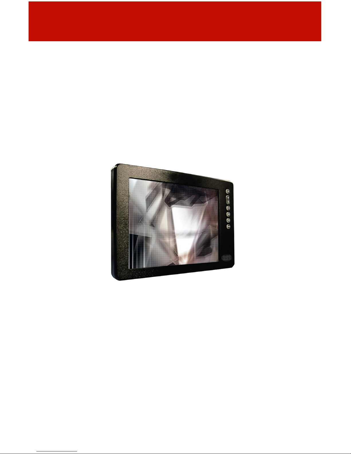
Wit h this purcha se of this All-Weat her M onit or DOD Serie s, we welcom e you t o
iTechLCD’s family of harsh-duty mobile computer products.
You will soon beco me fami liar with th e qualit y diffe re nce in this b rig ht sun lig h treadable (5 t o 800 n its ) Display, specifcally d esigned fo r mobile c o mpu ting. ITE CH h as
incorp o rated the latest op tic al en g in ee ring t o ach ieve o ptima l viewability in all lighting
conditions.
The DOD handles a wide-range of severe environments, making it the frst selection of
many indust ries for their mobile ap plicatio ns. Designed to be rugged, this 800 x 600
SVGA Flat Panel Display is eng ineered to thrive in its environmen t... wherever it will
be put it to work.
Housed in a milled billet aluminum case, the slim-profle DOD is light weight and
watertight, with ful l y sealed IP6 8 conn ectors. Engine ere d to operate on lo w power
consumption, the DOD manages a computer video input signal (VGA).
You may have purchased the DOD with the optional Analog Resistive Touch Screen;
within this User Manual are instructions for confguring this feature. Other options
includ e the Night Vision F ilter (NVIS), a pass-through US B port a n d an internal heate r,
necessary when working in critically low temperatures, down to -40ºC (-40ºF).
Our Mobile Computing Support Team is here for you – we are iTechLCD,
keeping Technology in Motion.
3
Page 4
SA FETY
General Saf et y I nstructio ns
• Before operating the DOD Display, read this User Manual thoroughly
• Keep this User Manual for future use
• Verify the computer system capab ility (see Sy stem Set-up) to insure operation of
the Display
• For expeditious installation, follow these User Manual instructions in sequence
• Adhere t o all Caution and Warnin g s on syste m an d as stat ed in this User Manu al
• User Manual instructions fo r insta llation and ope ration sho uld be followed precis ely
• Adjust only those controls covered by the User Manual’s operating instructions;
improper adjustment of other controls voids the Display’s warranty and may result
in Display damage, and
• Adhere to lo cal installa tio n cod es.
Safety Icons
General Unit Safety
• Always disconnect Display from power source before cleaning
• Do not operate Display with a damaged cable, and
• Do not operate if Display has been dropped or damaged. Unit should be inspected
by qualifed ITECH Service Personnel.
4
Page 5
Elect rical
Connecti ng Cables
• Disconne ct p ower to compute r when D isplay is being in st alled
• Upon installa tion, verify power inpu t connector is securely seated on Display
• Position power cable so it is not in contact with hot surfaces
• Do not allow anything to rest on power cable, and
• Protect power cable from extreme heat sources.
Power Source
• Always connect to a properly grounded DC (standard) power source
• Any equipment to which Display is attached must also be connected to properly
wired and grounded power sources
• Input voltage is 10 - 36 VDC, and
• Power Consumption is: 6 - 20 Watts maximum for DOD8400R, 1000R and 1200R
and 6 40 Watts for DOD1500R.
Servicing
User
• User Ser vic in g is li mite d to clea nin g th e D isplay
• Do not d isassemble o r modify th e Disp lay to av o id the po ssib ility of e lectrical
shock, damage to its electrical components or scratching the Display surface, and
• Disassembly voids the warranty.
ITECH
ITEC H Qu alifed Service P ersonnel may be r equired to service th e Disp lay if:
• Does not operat e normally w hen insta llat ion inst ructions a re fo llo wed
• Does not operate normally when operating instructions are followed
• Has been dropped or damaged, or
• Exhibits a distinct change in performance, indicating a need for service.
Shipping to ITECH Service Center
If Display should need to be shipped to the ITECH Service Center, the original
packing material should be used to insure safety of Display in shipping. Repack
Display as it originally received.
. 5
Page 6
PRODUCT CARE AND MAINTENANCE
Product Care
This DOD Display has b een d esigned to pr o vide op timum perfor ma n ce and service
without any required scheduled maintenance other than occasional cleaning.
Display Screen Cleaning
The Display Screen is a glass-based product.
• A vinegar-based cl eane r is preferred ; prev ents s treak ing and deg radation o f coa tings,
or a non-abrasive glass cleaner such as a professional foam glass cleaner
• Apply cleaning solution to a soft clean cloth, dampening slightly
• Keep a fresh side of cleaning cloth towards Display screen surface to avoid scratch-
ing with accumulated grit, and
• To minimize risk of abrasion to Display screen, air drying is recommended.
Optional Touch Screen
Touch Scr een Cl eaning
The Touch Screen Display is a glass-based product.
• Use a special screen cleaning tissue or a solution specifcally formulated for
antistatic coatings. Follow the manufacturer’s instructions, or
• Lightly dampen a soft clean cloth with water or a general purpose mild detergent
solution
• Keep a fresh side of the cleaning cloth towards the screen s urface to avoid
scratching it with accumulated grit, and
• To minimiz e the risk of abrasion to th e screen , air dry in g is recommen d ed.
Display Enclosure
• Clean the Display enclosure with a sof t c lean cloth lightly dampen ed with a gen eral
purpose mild detergent solution
• Wipe down with clean water, and
• Dry with a soft clean cloth.
6
Page 7
Long-term Storage
• For long-term storage, Display should be stored in a norma l indoo r environ ment and
Display screen be protected from accidental damage
• For p edesta l mo u nt D isplays, disc o n nect cab le(s ) and loosen ar m adjus tmen t to a
point where ball can be removed from arm, or
• For Flu sh or P anel Mount Disp lays, cove r D isplay w ith a pro te ct ive covering that will
not scratch or transfer dyes to Display screen.
Maintenance
Other Maintenance
Only IT E C H Qu alifed Ser vice Per sonn el sho u ld per fo r m all o th er main te n ance ex cept
for
cleaning and the power cable replacement described above.
.
SYSTEM SET-UP
Syst em Req uirem ents
The computer the DOD is connected to must have this capability:
• Video card setting with a minimum resolution of 640 x 480 pixels, and
• If th e option al To u ch Scr een D isplay is ordered, an av ailab le CO M or US B p o rt fo r the
connector is required, depending on the Display connector style ordered.
Shipping Box Contents
The DOD is shipped in a cus tom box with custom foam pa ckaging. The installer
shou ld save th e bo x and all packag in g materials in case the Display wou ld n eed to be
returned to the ITECH Service Center.
The Shipping Box contents are:
• DOD Display
• Pow er C able
• RGB (Computer) Input Cable
• Mounting System and Hardware
• Touch Screen Cab le if optional T o u ch Scre en Display is ordered
• USB Cable if optional USB Pass-through is ordered
7
Page 8
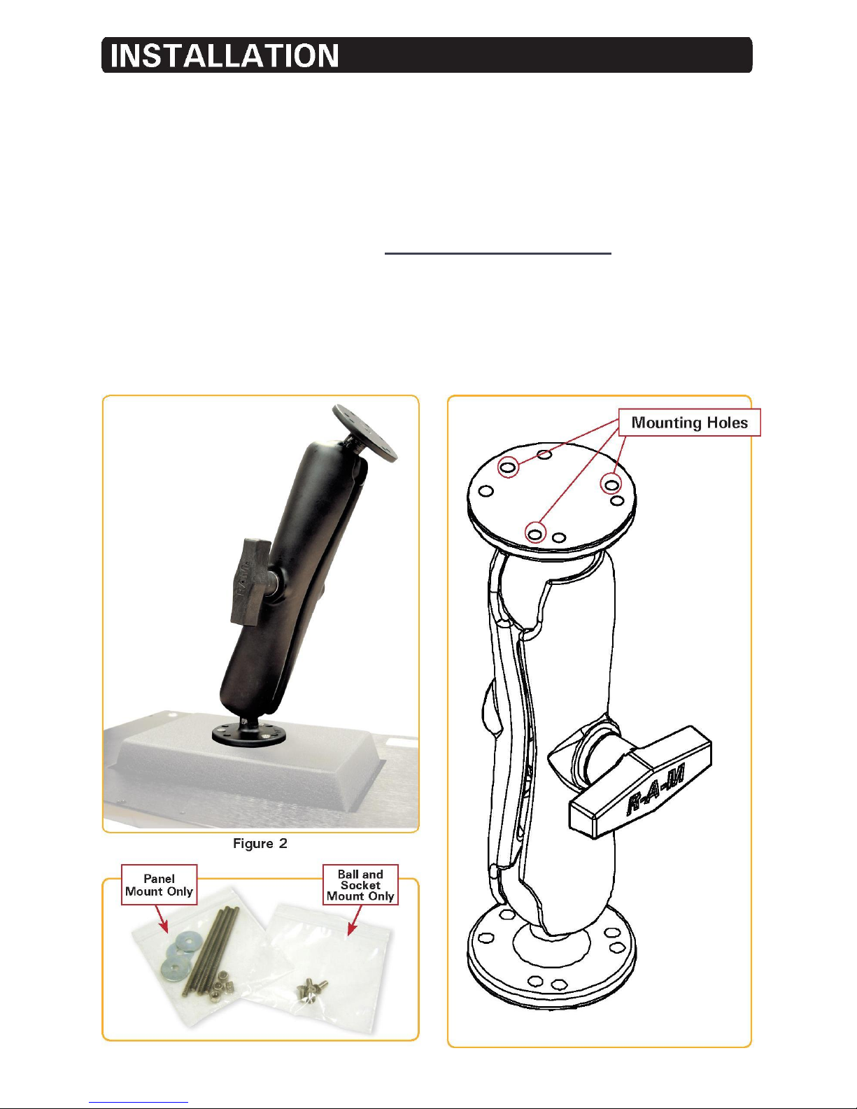
The DOD is designed to be mounted in three confgurations: with a universal ball-andsocket mounting kit, in a Flat Panel or optional Flush Mount confguration.
Pedestal Mount
The DOD is shipped with a RAM® unive rs al ball-and-socket system mountin g kit
(Figure 2). By installi n g th e Display with this kit, the User can adjust the viewing angle
to improve viewability in changing environments. This ball-and-socket system has
proven to be successful in supporting an extreme amount of weight in high vibration
and diffcult-mount applications. Visit www.itechlcd.com/installation for product
mounting diagrams.
Loca te th e ball-and-socke t system in the shipping box. Th e kit c o nsists of two RA M
balls on mounting plates and a RAM arm with an adjustable T-knob and a packet of
three (3) M4 x 10 counter-sunk stainless screws for mounting to the DOD. (Figures 2
- 4)
Figure 3 Figure 4
8
Page 9
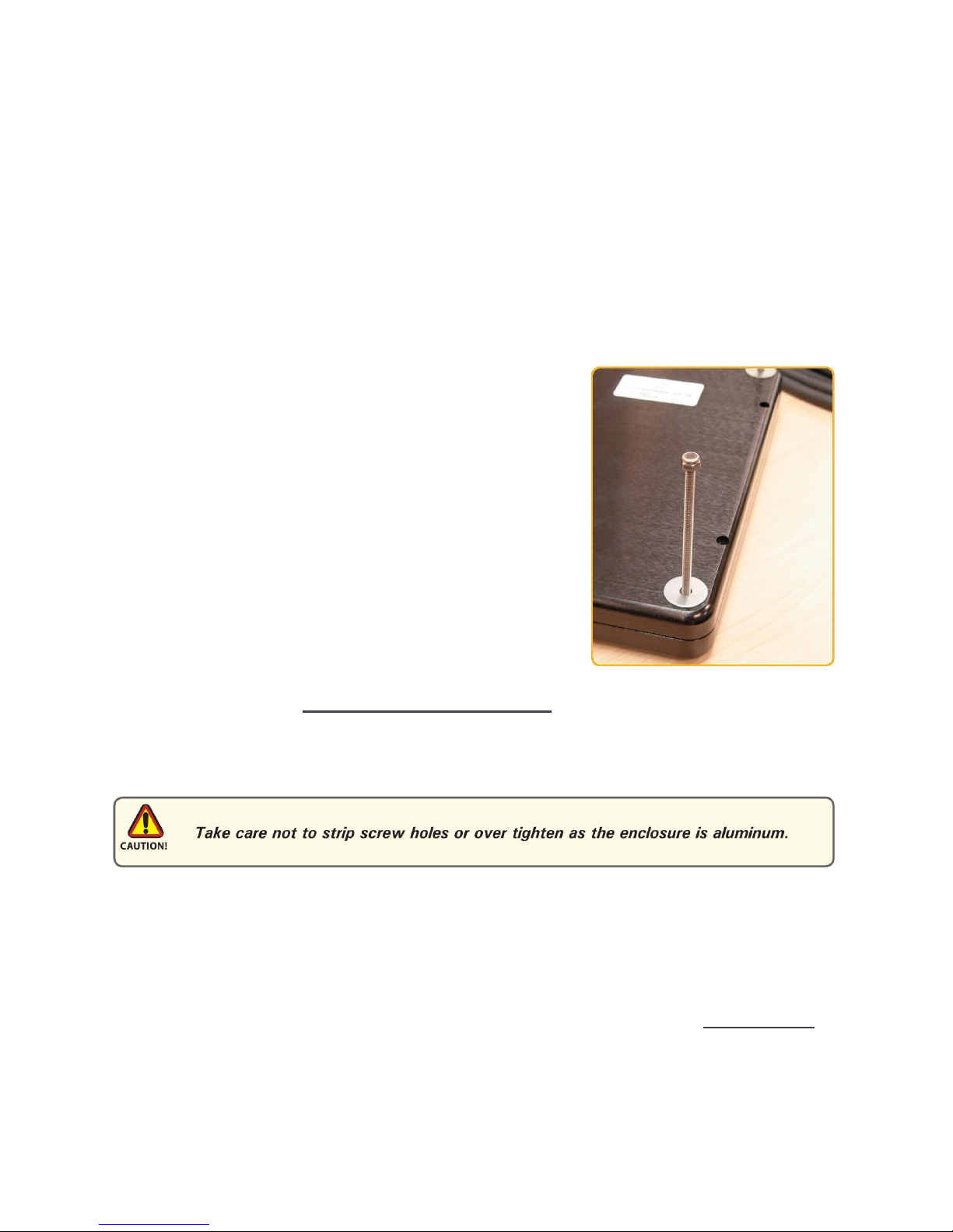
There are three mounting holes in the back of the Display for the attachment of a ball
mounting plate. Take care not to strip the screw holes or over tighten. (Figure 4)
It is recommended the remaining ball be mounted on a fat surface. Bec ause of the
various surface substrates where the Display is to be mounted, the installer provides
the screws to mount the other ball.
• Note the location of the three mounting holes on a ball mounting plate (Figure 4)
• With three (3) M4 x 10 counter-sunk stainless screws (Figure 3) attach mounting
plate to the back of the DOD (Figure 2)
• Mount the second ball mounting plate on the surface where the Display is to be
installed
• Insert each ball into the RAM arm
• Lightly tighten the arm around the balls using the T-knob on the arm (Figure 2, 4)
• Adjust the Display to the viewing preference, and
• Tighten the T-knob to hold the Display in position.
Panel Mount
Panel Mount installatio n should be specifed at time of
order; the ball-and-socket mount system will not be
included in shipping box. (Figure 5)
For installation, there are fo ur tapped mounting holes on
four corners of the Display’s rear panel. A mounting
hardware packet is i ncluded with product accessories i n
the shipping box. This packet includes four (4) M4
stainless s teel threade d s tuds, 7.6 cm ( 3” long), four (4)
Nylock self-locking nuts and four (4) fat washers.
It is recommended installer refers to the mount drawings
Figure 5
on ITECH’s web site, (www.itechlcd.com/installation), for exact m easurem ents of
Display’s rear panel pod. These drawings should be helpful when insta ller cuts the
required opening for the Panel Mount installation.
Flush Mount with Optional Bezel
Wit h the Flus h Mount Bezel , t he DOD Fl at Pan el Di spla y may b e mount ed fush with
mounting surf ace; bal l-and-socket mount system or any mounti ng hardware will not be
includ ed in the shipp in g box . Installer needs to supply screw s f o r this installatio n .
The mount diagram of the Flu sh Mount Bezel is on ITECH’ s web site, (www.itechlcd.
com/install ation). When placem ent sit e has been decided, it is r ecommended installer
use these measurements when cutting opening for Display’s installation.
Note Locations of milled holes in Flush Mount Bezel. Drill corresponding holes into the
substrate where Display is to be mounted.
9
Page 10
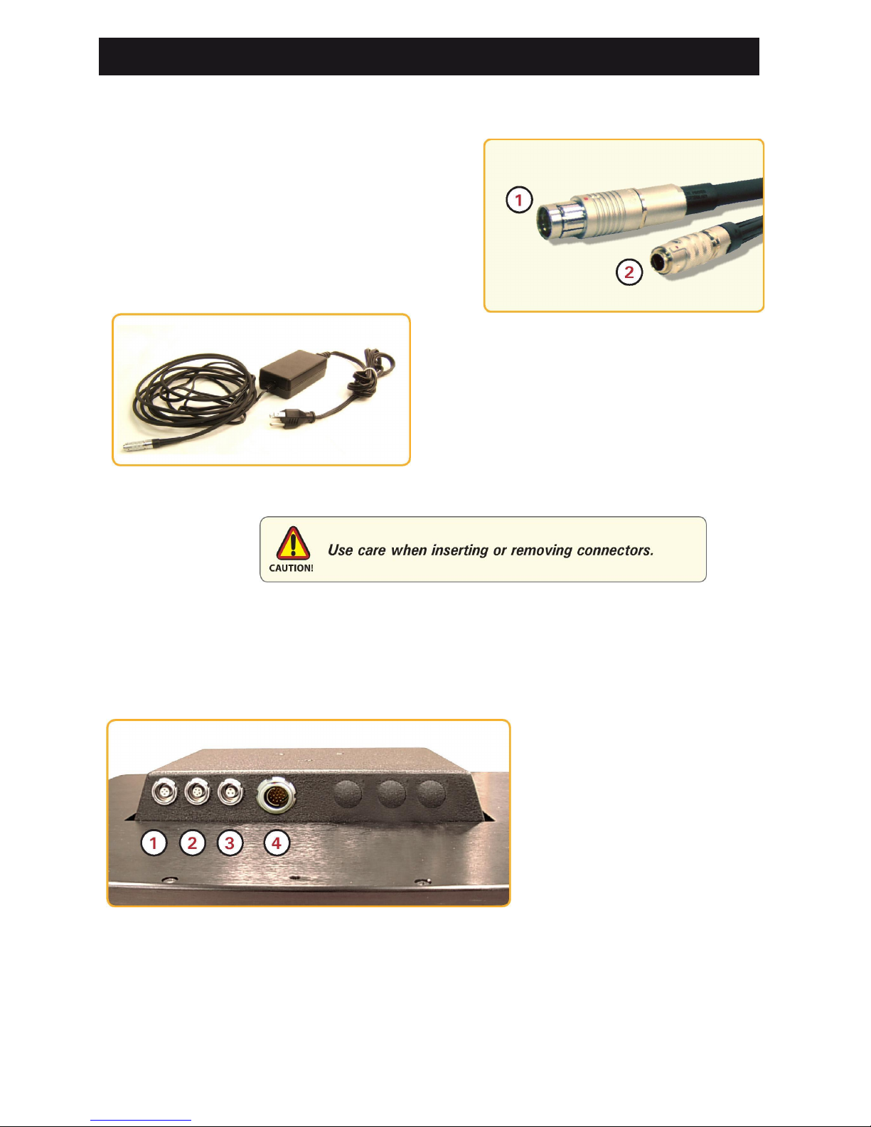
DISPLAY CONNECTIONS
Cab l es
• The DOD is packaged with two cables:
RGB (Com puter) I nput and DC Power , #1
and 2 in Figure 5
• The AC Power Adapter is optional. (Figure
6)
1 RGB (Computer) Input
2 DC Power Input
Figure 5
Figure 6
Connectors
Connectors are located on the bottom of the Display housing, from left to right:
Optional USB Pass-through, Optional Touch (Screen) and Power and Computer Input,
(Figure 7).
Connectors are physical ly un ique to insure the installer makes the prop er conne ctions .
1 Optional USB Input
2 Optional Touch Input
3 Power Input
4 Computer Input
Figure 7
Computer Input Connector
• The IP68 sealed Computer Input Cable, 3 m (10 ft), is in the shipping box
• Line up the red dots on the connectors
• Push the cable connector into Display’s Computer connector, #4 in Figure 7, and
• Plug the standard DB-15 (video) female connector to the computer’s video source;
secure.
10
Page 11

DC Power Connector
• The IP68 sealed DC Power Cable, 3 m (10
ft), is in the shipping box
• Line up red dots to Power Input connector,
#3 in Figure 7
• Plug in the quick-connect 3-pin connector
• To disconnect, pu ll ou tside ring on c onnec tor
away from Display until cab le is free
• Positive fying lead is marked with “+” label
• Negative lead is not marked (Figure 8)
Connect fying leads to corresponding polarity on DC voltage source, primary terminal.
OPTIONAL CONNECTORS
Optional USB Pass-throu gh Conn ector
• The optional USB Pass-through Connector is an IP68 sealed 4-pin connector
• The custom USB Cable is with the product accessories; it is .6 m (2 ft)
• Line up the red dots to USB connector, #1 in Figure 7, and
• Plug together.
• To disconnect, pull the outside ring on the connector away from Display until free.
Optional Touch Screen Connector
• The optional Touch Screen Connector is an IP68 sealed 5-pin connector
• The connector is next to the Power Connector
• The Touch Screen Cable is in the shipping box; it is 3 m (10 ft)
• Line up the red dots to Touch Connector, #2 in Figure 7, and
• Plug together.
OPTIONAL AC POWER ADAPT ER
Optional AC Power Adapter
• The optional AC Power Adapter Cable Set consists of a 3 m (10 ft) cable with an
IP68 sealed connector, the power adapter and a 1.8 m (6 ft) common AC power
cord (Figure 6)
• The adapter accepts voltage from 110 to 250 VAC and frequency from 47 to 63Hz
• The AC power cord plug is a North American standard for 120 VAC/60Hz
• Line up the red dots to Power Input connector, #3 in Figure 7, and
• To disconnect, pull the outside ring on the connector away from Display until free.
Note: The op tional AC Power Adapter is not an off-the-shelf item. It is equipped with a
specifc connector f or integration with the DOD Display.
11
Figure 8
Page 12

COMPUTER HOOK-UP
Compute r Display Propert ies - SVGA o r XGA
Prior to connecting the DOD to the computer, connect the computer to a CRT monitor
to verify the computer video display properties are set to 800 x 600 (SVGA) pixels or
if ordered, the optional 1024 x 768 (XGA) pixels. The 15” video Display is to be set
to 1024 x 768 pixels (XGA).
Setting the Display Setti ngs
1. Connect computer to a CRT moni tor to establish th e c omputer’s display pro p er ties
2. Right mouse click on an ope n area of the
desktop screen to bring up the Desktop Menu
3. Left mouse click on Properties to open the
Display Properties menu (Figure 9)
4. Sele ct t he Sett ings tab
5. Under Screen Resolution, verify or slide the
bar until the Screen Resolution is at 800 x 600
pixels (SVGA) or optional 1024 x 768 pixels
(XGA) (Figure 10)
6. S ele ct the Advan ced butto n; go to the ne xt
menu to verify the Hz refresh rate
7. Select the Monitor tab
8. Under Monitor Settings, verify the Screen
Refresh Rate is between 60 and 75Hz
• If so, select the Cancel button; go to Step 9
• If not, select a setting within the 60 – 75Hz
range, and
• Select the Apply button
Figure 9
Figure 10
12
Page 13

9. At the Monitor Settings dialog box, select
“Yes” to accept the new desktop view
settings (Figure 11)
10. In the Display Properties dialog box, verify
the Screen Resolu-tion is at 800 x 600
pixels (SVGA) or optional 1024 x 768
(XGA)
11. Select the Apply button
12. At the deskto p screen, shutdo wn the
computer
13. Turn off the monitor, and
14 . D isconnec t the m onitor fr om the c omputer.
Figure 11
Power on the Display
• Connect the DOD to the computer
• Power up the DOD, and
• Power up the computer.
• The Windows Operating System should auto matically apply the best generic driver
for this connection.
13
Page 14

OPERATOR CONTROLS
On the right hand side o f the Display bezel are
seven Operator Control buttons (Figure 12)
POWER ON /OFF Bu tton
Note: Display defaults to an AUTO-OFF state when power
is applied.
• Th e P OWER ON/ OF F b u tton is marked with
the I/O (Input/Output) symbol
• Momentarily pressing this button turns ON or
OFF the Display, and
• Blue LEDs glow behind the buttons when the
Display is powered on.
Select Button
The SELECT Button is used to start the OSD Menu. This button is also used to select
a function within the Men u. (See On-Screen Display.)
Up Arrow Button
The UP Arrow Button is an adjustment tool in the OSD Menu. (See OSD Menu Categories.)
Down Arrow Button
The DOWN Arrow Button is an adjustment tool in the OSD Menu. (See OSD Menu
Categories.)
Source Button
DOD handles one video source; SOURCE Button would be used to move between
video inputs withou t opening the OSD Menu. (See On-Screen Display section.)
14
B
rightness Button
The toggle button is second; it controls the
brightness of the Display.
• LARGE SUN button: when repeate dly pressed or held down will cause the
Display’s backlight brightness to step up in increments to its brightest setting
• SMALL SUN button: when repeatedly pressed or held down will cause the
Display’s backlight brigh tn ess to s te p down in in crements to its lo w est setting,
• Lowest Setting: is almost total black, suitable in very subdued lig h t, as in night time
operations, and
• Adjusted settings are maintained during power cycles.
Figure 12
Page 15

ON-SCREEN DISPLAY
The On-Screen Display (OSD) User Interface is where display adjustments are made.
With its user-friendly g raphical interface, the OSD Menu provides acces s to fne-tuning
the Display according to the User’s preferences.
OSD Menu Activation
To activate the OSD menu, press and release SELECT Button.
Note: OSD Menu closes after 30 seconds of inactivity. This setting may be adjusted in the OSD
Menu: Tools: OSD Timeout.
OSD Menu Categories
The OS D Menu is comprised of fv e icons and an Exit Button; each icon repres ents a
distinct menu category with its corresponding functions. (Figure 8)
Note: OSD Menu selections are indicat ed by icon only; there is no text.
Figure 8
General Operating Instructions
• To open the OSD Menu, press (once) the SELECT Button
• OSD Menu appears across bottom of Display screen;
• Use UP or DOWN Button to move across Menu; selected icon turns yellow (Figure 9)
Figure 9
• As Main Menu icon is highlighted, its Submenu appears in OSD dialog box
• Press (once) SELECT Button to enter selected Main Menu icon Submenu screen
• A hig h lig h t b ar is superimpose d o ver the frst menu item
• Press UP or DOWN Button to move the highlight bar through the Submenu
• Press (once) SELECT Button to activate the highlighted Submenu item
• To Change values: press UP or DOWN Buttons, which increases (UP) or decreases
(DOWN) the value of the parameter as indicated in OSD dialog box; hold Button
down to fast forward
15
Page 16

• Press (once) SELECT Button to go to a new menu item (Figure 10), or
• Press (once) SELECT Button to save new value o r w ait for OSD to ti meo u t; it will
auto-close, saving all changes
• To choose another menu item, use UP or DOWN Button to move across Main Menu;
repeat instructions, and
• To E xit , u se UP or DOWN B utton to move ac ross OSD Menu to h ig hlight Exit Sig n
icon; press (once) SELECT Button to Exit; upon Exit, all changes are saved.
Figure 10
OSD Menu Categories
In pu t S election
The Input Selection Menu enables a selection of thr ee Composite video input signals.
Selection is ba sed on Display confguration and its dependency upon a speci fc s i gnal
source. Main power recycle resets input source to default, C Video 1 (Composite).
Note: The SOURCE Button on the Display all ows for mo ving through various video inpu t si gnals
without accessing the OSD Menu.
C Video 1
Select for frst Input Signal. Select Exit Button to save.
C Video 2
Select for sec ond Input Signal. Select Exit Button to save.
C Video 3
Select for third Input Signal. Select Exit Button to save.
Exit
Select Exit Button to save changes and exit from OSD Menu.
16
Page 17

Image En h ancement
The Image Enhancement Menu enables adjustments of Image Enhancement values.
Sharpness
Select Sharpness to adjust Sharpness of displayed image. Use UP (right) or DOWN
(left) Button to adjust in preset increments. Select Exit to save.
Composite input signal factory default is 33 within a range of 0 - 100.
Black Level
Select Black Leve l to adjust Black L evel of input Composite Signal. Factory default is
50 within a range of 0-100. Use UP (increase) or DOWN (decrease) Button to adjust in
individual increments. Select Exit Button to save.
Contrast
Select Contrast to adjust difference in brightness between light and dark areas of
Di splay pixels. Factory default is 50 within a r ange of 0 - 100. Use UP (increase) or
DOW N (d ecrease) Bu tton to ad ju st in individual increments . S elect Exit B u tton to sa ve.
Exit
Select Exit Button to save changes and exit from OSD Menu.
Color
The Color Menu enables adjustments of Color Parameters of the Display image.
Composite Input Signal
Hue
Select Hue to a djust shading (gradation) within colors. Factory default is 50 within
range of 0 - 100. Use UP (increase) o r DOWN (decrease) Button to adju st in in d ividual
increments. Select Exit Button to save.
Saturation
Select Saturation to adjust intensity or vividness (saturation) of color. Factory default
is 50 within range of 0 - 100. Use the UP (increase) or DOWN (decrease) Button to
adjust in individual increments. Select Exit Button to save.
17
Page 18

Color R eset
Select Color Reset to reset active Composite signal Color p ara meters Hue and Satura-
tion to factory default values (50). Select Exit Button to save.
Note: Color parameters will reset active Composite Vid eo Input Signal only.
Exit
Select Exit Button to save changes and exit from OSD Menu.
Image Settings
The Image Setting Menu enables Display screen adjustments if Display is set-up for a
VGA Input Signal.
Note: Composi te: Icon will be grayed, as it is unavailable.
Tools
The Tool Menu enables adjustment of miscellaneous parameters.
OS D Timeout
Factory default OSD Timeout setting is 30 seconds. Interval selections are Off, 5, 15,
30 and 60 seconds. Select to adjust time elapse between last Menu activity and when
Menu exits. Use the UP (increase) or DOWN (decrease) Buttons to change the values.
Select Exit Button to save.
Note: Any changes made in will be saved upon Timeout Exit.
NVIS Green / NVIS Red
If unit is equipped with NVIS Green / NVIS Red option, User has to set the NVIS mode
to be active at power-on; Display will default to that NVIS color theme.
Use the UP ARROW Button to select NVIS Red.
Use the DOWN ARROW Button to select NVIS Green.
18
Page 19

Picture-in-Picture (PIP) Menu (Not Available with “R” Series; No Video Feed)
The User may view a second video source in addition to the default signal source by
utilizing the Picture-in-Picture (PIP) feature.
The PIP Menu has two selections: PIP Source; PIP Mod e.
PIP Source
PIP Source allows User to select the Composite Video Source (C 1 - 3) for the PIP.
PIP Mode
PIP Mode allows User to select Display Video S ource viewing mod es of OFF or P IP.
• OF F : tu rns off the PIP setting
• P IP: turns on the PIP view
• S et tin gs are maintained during power cycles (ON/OF F Button), and
• Settings return to factory default at main power recycle.
Factory Reset
Select Factory Reset to reset Display scr een adjustments Color Se ttings(Sharpness,
Black Level, Contrast) and Color (Hue, Saturation) to factory default values (50). Select
Exit Button to save.
Exit
Select Exit Button to save changes and exit from the OSD Menu.
OPTIONAL INTERNAL HEATER
Optional Internal Heater
The o ptional Internal H eater automatically brings th e Display up to th e standard
operating temperature if the Display is below that temperature when powered on.
Operations
• T h e f ashing blu e LED ligh ts b ehind the Operato r C o n trol Buttons indicate Display is
in the heating mode, bringing the Display up to operational temperature
• Once the D isplay is up to ope rational temperature , the fashing blue LEDs become a
const ant blue glow and the Display automatically powers on
• Maximum time for the Display to reach operational te mperature is approximately 12
minutes, and
• There are no User adjustments for the Internal Heater function.
19
Page 20

NVIS OPT IONS
NVIS Filter
ITEC H’s integrated NV IS options pro duce near zero to minimal color shift full sunlight
readability displays. The integrated NVIS complies with NVIS radiance value requirements of MIL-STD-3009 and MIL-L-85762A for Type 1, Class B, electro-optical displays and can be viewed with NVGs (Night Vision Goggles) through the entire brightness range.
Dimming is not necessary to meet MIL-STD-3009, Class B NVIS requirements.
Note: Display brightness levels will be reduced with the NVIS option.
NVIS Green / Red (OSD)
NVIS Green / Red OSD option allows in terfacing with Night Vision devices without
adverse effects. The Display will automatically power on in NVIS mode. Daylight
mode can be displayed by pushing the UP ARROW Button. This button allows User to
toggle between Day Mode and NVIS Mode.
User selects either NVIS Green or NVIS Red in the OSD menu. Once s ave d in the
OSD, the UP / DOWN ARROW Buttons will toggle between that selection (Green or
Red) and Day Mode; both NVIS colors are not available at the same time.
OPTIONAL USB PASS-THROUGH
CONNECTOR
Note: The USB Pass-through Connector on the other end is standard A-type USB port
socket and is not sealed.
Optional U SB P ass-Thro ugh C on necto r
The optional USB Pass -through Connector signal is sent th rough the Touch Screen
(T/S) cable connection to the computer.
• Install T/S 5-pin connector to the Display’s rear pod, #2, Figure 7
• Install T/S cable’s USB connector to any computer US B port, and
• Install 4-pin, .6m (2 ft) USB Pass-through Cable to Display’s rear pod, #1, Figure 7
Optional USB Pass-Through Connector with Touch Screen Display
The optional USB Pass -through Connector signal is sent th rough the Touch Screen
(T/S) cable connection to the computer.
• Install T/S 5-pin connector to Display’s rear pod, #2, Figure 7
• With split end of T/S Cable, install the USB connector to any computer USB port
• Install the other end, the Touch Screen Display RS-232 Connector, to a computer
serial port, or
• Install the other end, the Touch Screen Display USB Connector, to a computer USB
port
• Install the IP68 sealed 4-pin, .6 m (2 ft) USB Pass-through Cable to Display’s rear
pod, #1, Figure 7.
20
Page 21

OPTIONAL TOUCH SCREEN DISPLAY
Operat ing Syst ems
Operating Sy st ems compa tib le with TS H ARC Touch Screen Controller Drive r a re: Windows 98se, 2000, ME and XP. It is not compatible with Microsoft Vistas.
DOD Optional Touch Screen Install ation
Previous Versions of Touch Screen Controller Drivers
Unin st all T SHARC ™ Driv ers Ut ility
Uninstall a Previous Version of the TSHA RC Driver
The uninstall utility TSUN10.exe is available on ITECH’s web site: www.itechlcd.com.
Go to the Support tab > Drivers Touch Screen Driver > Uninstall Utility. This utility
uninstalls TSHARC drivers only.
To download the utility, left double
mouse click on the fle name.
At the File Download dialog box, select
Save (Figure 13) > Save the fle to the
computer’s program fles > Make a new
folder: TSHARC Uninstall > Select Open
> Save the TSUN10.exe fle > At the
dialog b o x: Down lo ad is comp let e, selec t
Open Folder > Left double mouse click
on TSUN10.exe to execute the utility
> At the dialog box: Do you want to
remove, select Yes > At the dialog box:
Press OK to complete t h e uninstall, select OK > At the uninstall confrmation
screen, select OK. F o llow instructions.
Figure 13
21
Page 22

Previous Versions of Other Manufacturers’ Touch Screen Drivers If a different
T/S Controller Driver (not TSHARC) is on the computer, it must be completely
removed b ef ore installing th e TSHARC. No te: T h e typical driver uninstall prog ra m or
Microsoft’s® remove program utility does not remove all tracks of a T/S Driver
installation. Co n ta ct the man u fa ct u rer of the previously installed drive r program to
learn how to completely uninstall their product. These instructions may be available
from the manufacturer’s web site.
Touch Screen Installation
TSHARC Touch Screen Controller Driver
The TSHARC T/S Controller Driver fles are available on ITECH’s web site:
www.itechlcd.com. Go to the Support tab > Drivers Touch Screen Driver > Operating
System.
Installa tion
1. Verify the T/S Cable is co nn ected to the Displ ay or attach the T/S Cable’s 5-pin
connector to the Display’s 5-pin connector #2, Figure 7
2. Atta ch the T/S Cable ’s RS-232 conn ect or to the com put er seri al ( COM) port where
the T/S will be installed, or
3. If the T/S was orde red with a USB connector, insert the cabl e to the computer USB
port where the T/S will be installed, and
4. If the optional USB Pass-through was ordered, attach the T/S Cable’s other split
end connector, the USB, to a computer USB port.
Note: For Multi-Display Touch Screen applications, all Monitors must be connected to the
computer before installing the TSHARC driver.
5. Boot u p the computer; do wnload the Driver zip fle to the Desktop
6. On Desktop, left double mouse click to open
7. Follow i nstructions to unzip the fl e
8. Save fle where User chooses, and
9. Left mouse double click to run “set-up.exe”
10.Follow instructions.
USB Touch Screen: Basic Power ON /OFF Ins tructions
22
Page 23

TSHARC Installat ion
EULA Agreement
Figure 14
1. At Welc o me screen, select Next to go to End
User’s (Software) License Agreement (EULA)
2. After reading EULA, if in agreement, check box
“I accept all of the terms…” (Figure 14), and
3. Select Next
4. If not in ag reement, follow instructions and Exit.
Note: Any unlawful use of the TSHARC driver is a strict
violation of United States and International copyright
laws. Using a TSHARC driver with any third party Touch
Screen is strictl y prohibited.
Select Control ler
Note: A PS/2 Controller Interface is not available.
1. The TSHARC Driver is a 12-bit Controller; the radio
button is selected by default
2. Select Controller Interface matching the cable used
to install the DOD - serial or USB
3. Select Autodetect button if installing the T/S through
a RS-232 (serial) Interface
4. The re are t wo options for RS-2 32 installation: Autodetect and Manual. Manual instructions are found
in section Manual RS-232 Controller Set-up (Figure 15)
5. I f connecting through a USB Interface, select the USB radio button
6. Select Next
7. Following installation, select Finish, and
8. Reboot computer when prom pted.
Autodetect RS-232 Controller Set-up
1. Select Autodetect button
2. The “AutoDetect Serial” dialog box lists the detected RS-232 Controller
information. Select OK
3. “Installing Touch Screen Driver” text box pops up, indicating the progress of
installation
4. Following installation, select Finish, and
5. Reboot computer when prom pted.
23
Figure 15
Page 24

Manual RS-232 Controller Set-up
1. Sel ect Controller Interface RS-232 butt on
(Figure 16), and
2. Select Next Note: Do not select
Autodetect
3. Enter COM port sele cti on
4. The T/S Controller baud rate default is 9600
Note: This is a Resistive T/S Display. The Capacitive
Controller option is not availa ble.
5. Select Next
6. Followin g installation, select Fin ish, and
7. Reboot computer when prompted.
Enabl e Touch Screen Tray Icon
1. If User wants a T/S Controller tray icon
(associated with Display Rota tional Menu) in
toolbar tray, select box (Figure 17), or if User will
be in stalling Third- P arty Display Rotation D r ivers,
enable the T/S Tray Icon, and
2. Select Finish button; TSHARC driver is installed.
Figure 16
Figure 17
Disabl e Touch Screen Tray I con
If User does not want a T/S Controller tray icon to show in the toolbar tray, select
the Finish button; the TSHARC driver is installed.
Installation Complete
At dialog box, “Set-up is now co mplet e”, select OK, e xit ing TSHARC T /S Controller
installation.
TSHARC Calibration Program
Upon reboot, the T/S is functional, but not calibrated. Calibration must be confgured
for the T/S to work properly. The TSHARC Control Panel initiates the calibration
process.
• Go to Start > Programs > Hampshire TSHARC Control Panel. The Control Panel
has several tabs. Each tab provides links to tools to modify the TSHARC Driver to
meet specifc needs:
• Screen Selection
• Calibration
• Edg e Acceleratio n
• C lick Setting s
• Touch Settings
• Capacitive Settings (disabled)
• Tools
Note: The D OD is a Resist ive Touc h S creen : the Ca pacitive Setting is disabled.
24
Page 25

TSHARC Control Panel
Scr ee n Sel ect i on
Note: If this is not a Multi-Display installation, skip to
section Calibration.
Confguring a Multi-Display Installation
Note: Microsoft does not support a Multi-Display
installation in Windows 98se.
1. The Controller installation program opens to
Screen Selection tab. Note graphic representation
of Displays installed on the system (Figure 18)
2. Using keypad or the mouse, in shown numbered
sequence select Display icon to calibrate
3. Sw itch to Calibration tab.
4. When cal i brat ed, return to Screen Selection tab;
in sequence select next Display. Repeat process
until all Displays are calibrated.
Calibration General Instructions Calibration
aligns the T/S overlay to specifc points on the
Display screen.
1. I n ten seconds the Calibration program launches,
or sele ct Calibration tab (Figure 19)
2. Defaul t Calibration process is Four-Point, the
best known gene ral calib ration; it co mpensa tes
for skew and some edge linearity anomalies,
3. To calibrate to Four-Point, select Begin Alignment button, and
4. Go to section Calibration Process
Figure 18
Figure 19
Custom Calibration Settings
1. To customize the Calibration process, select Calibration tab to bring up optional
Calibration Points menu (Figure 20)
2. Above Alignment button is Inset Slide Bar which moves edge calibration points into
the display screen area if User wants to calibrate the edges of the T /S more
precisely. Default is 20%.
3. Linearization (equates to touch accuracy): Varied linearity exists between T/S
types; On the left menu, click on number of Calibration points to confgure:
• Four-Point: A quick calibration of a known good T/S
overlay with no correction applied.
• Five-Point: Compensates for skew and so me edge
linearity anomalies.
• Nine-Point: More accurate than Five-point calibra-
tion. No correction is applied.
• Twenty-Five Point: Provid es a higher level of T/S
linearization and skew correction.
• Twenty-Eight Point: Provides the highest level of
T/S li n earizatio n.
25
Figure 20
Page 26

Calibration Process
1. Select ‘Begin Alignment’ button
2. Press graphic Target to start calibrat ion (Figure 21)
3. Targets are used to calibrate the Touch Screen. Follow the
on-screen instructions - ’Touch‘ the target center, ‘Hold’
until it shrinks, then ‘Release’ the target
4. Repeat process for all Targets, and
5. When completed, select ‘Apply’.
Note : Calibration s cree n retu rns to C alib ration tab i f frs t poin t is not
touched within 10 s eco nds.
Calibr ation Verifcatio n Drawing
1. Select Tools tab
2. Select Drawing button
3. Usin g a fnger or stylus, dr aw or write (Figure 22)
4. Obser ve if screen displays drawing accurately. If it does
not, re p eat Custom Calibration Set tin g s and Calibration
Process instructions, and
5. When satisfed, select Quit button to exit; go to next step.
Edg e Acc el erat io n
1. Select Edge Acceleration tab (Figure 23)
2. Adjust the four edges of display screen to validate edge
calibration; default is 0%; adjust up to 25% on each
display edge
3. U se a fnger or styl us t o verify touch accurac y on edges
4. If accurate, select Apply button.
Click Sett ing s
Right Click
If desire d for T/S app lication, check “Enable
Right Click” box to set right click option (Figure 24).
Right Click A rea
Use slide bar to set the T/S event area to a size slightly larger
than the activator – larger for a fnger tip, smaller for a stylus;
box displays the activator size.
Right Click Delay
The timed-hold right click mous e event allows User to
initiate a right click by holding down a touch point for a
specifc time period.
Use slide bar to set Right Click Delay value to time
necessary to produce a right click event.
Double Click A rea
This step sets the area that allows for a double click event. Limit this to areas that
may be accurately touched several times.
Use slide bar to set double click area; box displays the activator size.
Double Click Speed
1. Use slide bar to set suf fcient time to perform a double touch in specified area
2. Sele ct Apply button to enter sel ection, and
3. Select OK button to apply all Click Settings.
Figure 21
Figure 22
Figure 23
Figure 24
26
Page 27

Touch Settings
Normal
Emulat es a standar d mouse, allowing a single c lick,
double click, drawing, dr agging and right click option
(if enabled) (Figure 25).
Touch Do wn
Allows for a click even t to take place at touch down .
No d raw o r drag is available.
Touch Up
Touch only. Double click is disab led. If right click
was earlier enabled , it is n ow disabled.
Figure 25
Touch Sound
1. Check Enable T ouch Sound to enable a tonal beep when screen is touched
2. Sele ct Apply button to enter sel ection, and
3. Sel e ct OK butt on to apply all Touch Setti n gs.
Capacitive Tab – Disabled
The T/S is a Resistive type; the Capacitive Tab is disabled.
Synchronize d Tou ch Scr een w ith Third- Party Di s play Rotation Drivers
The T/S may be set to automatically rotate when Display is rotated by third-party
Display Rotation Drivers.
1. Right click on System Tray icon, and
2. From TSHARC Rotation Control Panel Menu, enable (select) “Autodetect Rotation”.
Preset t ing Autodetect Rotation Parameters
To synchronize T/S with Display, map T/S rotation with all User-required Display
rotations.
1. Verify “Autodetect Rotation” is enabled
2. Rotate Display to al l rotations needed using third-party Display Rotation program
3. Apply changes, and
4. Touch target displayed by TSHARC driver.
Note: User s hould only need to synchronize Tou ch Screen with Disp lay Rotation Drivers one time.
27
Page 28

APPENDIX A
Mechanical Drawings
Mount diagrams of DOD and dimensio n s may assist w ith installation of D isplay. These
may be found on the ITECH website: http://www.itechlcd.com/installation.html
Optional Mounts
Diagrams of Flush, Pane l or Rack Mounts and dimensions may assist wi th insta llation
of Display. These may be found at: http://www.it echl cd.com/installation.html
APPENDIX B
Troubleshooting
Symptom: No light behind button L EDs
Possible Problem
Solution
No power, loose power con nection
Conf
i
rm the Display is properly connec ted to a
DC or AC power source.
Verify the power source is live or try another
batter y or AC power outlet.
Verify the Display is powered on.
Reverse polarity Check polarity of the powe r c onnection.
Symptom: Light behind button LEDs, no display or “No Signal” error
message and/or no image on the Display
Possible Problem
Solution
Power on, no video signal
Verif y the video ca ble is plug ged in to the Com
-
puter Input video connector.
Verify a video signal is coming out of the
compute r (i.e., plug into a known good d isplay
source).
Verify the incoming signal source selected
matches the Computer Moni tor signal source.
Check the Brightness front panel (LCD) adjustment on the Display. This may be set too low.
Check the Brightness and Contrast controls in
the OSD. These may be set too low.
Computer may have gone into power management stand-by. Press any key on the k eyboard,
move the mouse or cursor, or if there is a Touch
Screen, touch to wake the computer.
Symptom: Display has rolling “bars” acros s t he s creen or ve rtic al
shaded bars on the image.
Possible Problem
Solution
Computer video display is not set to view at
800 x 6 00 pixels or 1024 x 768 pixels
Verify computer video display is set at 800 x
600 pixels (1024 x 768 pixels).
28
Page 29

Symptom: (continued) Displ ay has rolling “b a rs ” ac ross the screen or
vertical shaded bars on the image.
Symptom: Picture quality, i m age s tab ility is distorted.
Possible Problem
Solution
Not working in 800 x 600 pixel resolution or
1024 x 76 8 pixel res olution
Verify computer video display is set at 800 x
600 pixels (1024 x 768 pixels).
Proper cable grounding and shielding
Verif y the use of a proper video cable with
suitable grounding and shielding. Keep the
video cable away from sources o f EMI an d
RFI.
Improper video display setting s Check signal source for a proper signal.
Verify computer video display is set at 800 x
600 pixels (1024 x 768 pixels).
Verify the display refresh rate: 60 – 75Hz.
Display unit is farther than 3 m (10 ft) from
si gnal source
Single cable lengths in excess of the standard
3
m (10 ft) cable should be of high quality
shield ed Computer Input cable. C ont act ITECH
for infor mation on custom cables.
Multiple Monitors are driven from the same
signal source.
Splitting the video signal divides the strength
of the s ignal. A video signal booster (line
driver) is recommended if installation requires
more than one Display dri ven from a single
video so ur c e.
Display has incorrect or bad sync signals.
Check for proper video cable installation, or
replace suspected faulty cable.
Verify computer video display is set at 800 x
600 pixels (1 024 x 768 pixels) and at a 60 75Hz refresh rate.
Symptom: Disp lay image is not proper l y sized
Possible Problem
Solution
OSD ad justments need to be made
Adjust the vertical and horizontal size controls
through the OSD.
Improper video display setting s
Verify
computer video display is set at 800 x
600 pixels (1 024 x 768 pixels) and at a 60 75Hz refresh rate.
29
Possible Problem
Solution
Defective video cable
On a known good display source, confirm
the video cable is not defective.
Interference fr om ad jacen t eq uipme nt
For proper groun
ding and shielding, verify use
of a proper video cable.
Keep the cable away from sources of EMI such
as electric motors, or unshielded RFI
sources such as radar and microwaves.
Horizontal size is not adjusted In the OSD, adjust the horizontal size control.
Page 30

Symptom: Touch Screen (T/S) do es not r espond
Possible Problem
Solution
T/S cable is not plugged in
Verify the connections between the
T/S and
the computer.
T/S cable is installed in a di fferent COM port
than in stalled by the software
Install the T/S into another COM port. If using a
laptop, verify the COM port(s) is enabled.
T/S Controller driver has not been installed Install the TSHARC Controller driver.
Hardware failure
Contact a
ITECH
Technical Support Technician
(480.515.1110).
Symptom: T/S moves, but does not follow a fnger or stylus
Possible Problem
Solution
Controller is not calibrated
Run the calibration in the TSHARC Cont
rol
Panel sof t w are.
T/S Contro ller Driver is not installed Install the TSHARC Controller Driver.
T/S cable is not installed correctly Verify the T/S cable is installed correctly.
Symptom : “Error in Calibration” message appears
Possible Problem
Solution
The T/S Controller Driver is not installed
correctly
Uninstall the driver using
“
TSUN10.exe
”
. If a
previous T/S Controller Dri ve r was inst alled, all
footprints must be removed. Go to the T/S
manufacture r’s web site or contact the manufacturer for instructions to uninstall driver.
Reinstall the TSHARC Driver software.
APPENDIX C
NEMA and IP Industry Standards
Two major electrical manufacturing organizations monitoring product enclosures and/
or their degree of protection; each organization publishes technical manufacturing
standards. The National Electr ical Manufacturers Association (NEMA) Standard No.
250 – 2003 addresses non-hazardous locations, enclosure design and environmental
performance requirements. These are referred to as NEMA Types. (www.nema.org )
The International Electrotechnical Commission (IEC) 60529 Standard addresses
Ingress Protection (IP); this describes the degree of enclosure protection provided, not
the en closure itself. Th e f rs t digit of IP Code designatio n desc rib es degree of p ro tection against ingress of solids; second digit designates degree of protection against
ingress of liquids. IP Codes support NEMA Type designations. (www.iec.ch)
iTech LCD designs the DOD sealed Display to exceed Standards of NEMA 6 and IP67,
incorporating a range of environmentally-sealed connectors engineered to provide a
safe and secure dust and waterproof environment in rugged conditions.
Summary of NEMA 6/IP 67: Enclosures constructed for indoor or outdoor use; to provide a degree of protection to personnel against incidental contact with the enclosed
equipment; to provide a degree of protection against falling dirt; against hose-directed
water and the entry of water during occasional temporary submersion at a limited
depth (6” to 3 feet or 15cm to 1m); and that will be undamaged by external formation
of ice on the enclosure. Sealed from dust and water.
30
Page 31

iT
echLCD
COMPANY LLC
www.iT echLCD.com
TOLL FREE: (888) 483-2418
EMAIL:
info@itechlcd.com
 Loading...