

Page 1
Distributed by
i-Tech Company LLC
TOLL FREE: (888) 483-2418 • EMAIL: info@i-techcompany.com •
WEB: www.i-techcompany.com
Page 2

Page 3

Warnings and Cautions:
INSTALLATION INSTRUCTIONS
SECURE RACKING
If Secure Racked units are installed in a closed or multi-unit rack assembly, they may require
further evaluation by Certification Agencies. The following items must be considered.
1. The ambient within the rack may be greater than room ambient. Installation should be such
that the amount of air flow required for safe operation is not compromised. The maximum
temperature for the equipment in this environment is 45°C. Consideration should be given to
the maximum rated ambient.
2. Installation should be such that a hazardous stability condition is not achieved due to
uneven loading.
Input Supply
Check nameplate ratings to assure there is no overloading of supply circuits that could have an
effect on overcurrent protection and supply wiring.
GROUNDING
Reliable earthing of this equipment must be maintained. Particular attention should be given
to supply connections when connecting to power strips, rather than direct connections to the
branch circuit.
No Serviceable Parts Inside; Authorized Service Personnel Only
Do not attempt to repair or service this device yourself. Internal components must be serviced by
authorized personnel only.
• Shock Hazard - Do Not Enter
Disconnect Power
If any of the following events are noted, immediately disconnect the unit from the outlet and
contact qualified service personnel:
1. If the power cord becomes frayed or damaged.
2. If liquid has been spilled into the device or if the device has been exposed to rain or water.
i
Page 4

CMS-6R4 Series - User’s Guide
FCC Part 15 Regulation
This equipment has been tested and found to comply with the limits for a Class A digital device,
pursuant to Part 15 of the FCC rules. These limits are designed to provide reasonable protection
against harmful interference in a residential installation. This equipment generates, uses, and can
radiate radio frequency energy, and if not installed and used in accordance with the instructions,
may cause harmful interference to radio communications. However, there is no guarantee that
interference will not occur in a particular installation. If this equipment does cause harmful
interference to radio or television reception, which can be determined by turning the equipment
off and on, the user is encouraged to try to correct the interference by one or more of the following
measures:
• Reorient or relocate the receiving antenna.
• Increase the separation between the equipment and receiver.
• Plug the equipment into an outlet on a circuit that is different from the one used by the
receiver.
• Consult the dealer or an experienced radio/TV technician for help.
This device complies with Part 15 of the FCC rules. Operation of this device is subject to the
following conditions: (1) This device may not cause harmful interference, and (2) this device must
accept any interference that may cause undesired operation.
WARNING: Changes or modifications to this unit not expressly approved by the
party responsible for compliance could void the user’s authority to operate the
equipment
EMC, Safety, and R&TTE Directive Compliance
The CE mark is affixed to this product to confirm compliance with the following European
Community Directives:
• Council Directive 89/336/EEC of 3 May 1989 on the approximation of the laws of Member
States relating to electromagnetic compatibility;
and
• Council Directive 73/23/EEC of 19 February 1973 on the harmonization of the laws of
Member States relating to electrical equipment designed for use within certain voltage
limits;
and
• Council Directive 1999/5/EC of 9 March on radio equipment and telecommunications
terminal equipment and the mutual recognition of their conformity.
Industry Canada
This Class A digital apparatus complies with Canadian ICES-003.
Cet appareil numérique de la classe A est conforme à la norme NMB-003 du Canada.
This product meets the applicable Industry Canada technical specifications
The Ringer Equivalence Number is an indication of the maximum number of devices allowed
to be connected to a telephone interface. The termination on an interface may consist of any
combination of devices subject only to the requirement that the sum of the RENs of all the devices
does not exceed five
ii
Page 5

Table of Contents
1. Introduction . . . . . . . . . . . . . . . . . . . . . . . . . . . . . . . . . . . . . . . . . . . . . . . . . . . . . . . . . . 1-1
2. Unit Description
2.1. Front Panel Components . . . . . . . . . . . . . . . . . . . . . . . . . . . . . . . . . . . . . . . . . . . . 2-1
2.2. Back Panel Components . . . . . . . . . . . . . . . . . . . . . . . . . . . . . . . . . . . . . . . . . . . . 2-2
3. Quick Start
3.1. Hardware Installation . . . . . . . . . . . . . . . . . . . . . . . . . . . . . . . . . . . . . . . . . . . . . . . 3-1
3.1.1. Apply Power to the CMS-6R4 . . . . . . . . . . . . . . . . . . . . . . . . . . . . . . . . . 3-1
3.1.2. Connect your PC to the CMS-6R4 . . . . . . . . . . . . . . . . . . . . . . . . . . . . . . 3-1
3.2. Communicating with the CMS-6R4 . . . . . . . . . . . . . . . . . . . . . . . . . . . . . . . . . . . 3-2
3.3. Connecting Ports and Switching Outlets . . . . . . . . . . . . . . . . . . . . . . . . . . . . . . . . 3-4
4. Installation
4.1. Power Supply Connection . . . . . . . . . . . . . . . . . . . . . . . . . . . . . . . . . . . . . . . . . . . 4-1
4.1.1. Installing the Cable Keeper . . . . . . . . . . . . . . . . . . . . . . . . . . . . . . . . . . . 4-1
4.2. Connecting Devices to the Switched Outlets . . . . . . . . . . . . . . . . . . . . . . . . . . . . . 4-1
4.3. Connecting Devices to the RS232 Serial Ports . . . . . . . . . . . . . . . . . . . . . . . . . . . 4-2
4.4. Connecting Control Devices to the CMS-6R4 . . . . . . . . . . . . . . . . . . . . . . . . . . . . 4-2
4.4.1. Control via Local PC . . . . . . . . . . . . . . . . . . . . . . . . . . . . . . . . . . . . . . . . 4-2
4.4.2. Control via Modem . . . . . . . . . . . . . . . . . . . . . . . . . . . . . . . . . . . . . . . . . 4-2
4.4.3. Connecting the Network Cable . . . . . . . . . . . . . . . . . . . . . . . . . . . . . . . . 4-2
5. Configuration
5.1. Supervisor Mode and Non-Supervisor Mode . . . . . . . . . . . . . . . . . . . . . . . . . . . . 5-1
5.2. Communicating with the CMS-6R4 . . . . . . . . . . . . . . . . . . . . . . . . . . . . . . . . . . . 5-2
5.2.1. Accessing the Web Browser Interface . . . . . . . . . . . . . . . . . . . . . . . . . . . 5-3
5.2.2. Accessing the Text Interface . . . . . . . . . . . . . . . . . . . . . . . . . . . . . . . . . . 5-4
5.3. System SetUp Port . . . . . . . . . . . . . . . . . . . . . . . . . . . . . . . . . . . . . . . . . . . . . . . . . 5-5
5.4. Password Functions . . . . . . . . . . . . . . . . . . . . . . . . . . . . . . . . . . . . . . . . . . . . . . . . 5-6
5.5. Configuration Menus . . . . . . . . . . . . . . . . . . . . . . . . . . . . . . . . . . . . . . . . . . . . . . . 5-7
5.5.1. The System Parameters Menu . . . . . . . . . . . . . . . . . . . . . . . . . . . . . . . . . 5-7
5.5.1.1. The Password Directory . . . . . . . . . . . . . . . . . . . . . . . . . . . . . . 5-10
5.5.1.2. Adding Passwords . . . . . . . . . . . . . . . . . . . . . . . . . . . . . . . . . . 5-12
5.5.1.3. Editing Passwords . . . . . . . . . . . . . . . . . . . . . . . . . . . . . . . . . . 5-15
5.5.1.4 Deleting Passwords . . . . . . . . . . . . . . . . . . . . . . . . . . . . . . . . . 5-16
5.5.1.5. Deleting the Entire Password Directory . . . . . . . . . . . . . . . . . 5-16
5.5.1.6. The Dial Back Function . . . . . . . . . . . . . . . . . . . . . . . . . . . . . . 5-17
5.5.2. Network Parameters Menu . . . . . . . . . . . . . . . . . . . . . . . . . . . . . . . . . . 5-19
5.5.2.1. IP Security Feature . . . . . . . . . . . . . . . . . . . . . . . . . . . . . . . . . . 5-22
5.5.2.2. Telnet Port Parameters . . . . . . . . . . . . . . . . . . . . . . . . . . . . . . . 5-25
5.5.2.3. The Invalid Access Lockout Feature . . . . . . . . . . . . . . . . . . . . 5-28
5.5.3. RS232 Port Parameters . . . . . . . . . . . . . . . . . . . . . . . . . . . . . . . . . . . . . 5-29
5.5.3.1. RS232 Port Modes . . . . . . . . . . . . . . . . . . . . . . . . . . . . . . . . . . 5-35
5.5.3.2. Copying Parameters to Several Ports . . . . . . . . . . . . . . . . . . . . 5-36
5.5.4. Configuring the Internal Modem . . . . . . . . . . . . . . . . . . . . . . . . . . . . . . 5-38
5.5.5. Plug Parameters Menus . . . . . . . . . . . . . . . . . . . . . . . . . . . . . . . . . . . . . 5-39
5.5.5.1. The Boot / Sequence Delay Period. . . . . . . . . . . . . . . . . . . . . . 5-41
5.6. Save Configuration Parameters . . . . . . . . . . . . . . . . . . . . . . . . . . . . . . . . . . . . . . 5-42
. . . . . . . . . . . . . . . . . . . . . . . . . . . . . . . . . . . . . . . . . . . . . . . . . . . . . . . 2-1
. . . . . . . . . . . . . . . . . . . . . . . . . . . . . . . . . . . . . . . . . . . . . . . . . . . . . . . . . . . 3-1
. . . . . . . . . . . . . . . . . . . . . . . . . . . . . . . . . . . . . . . . . . . . . . . . . . . . . . . . . . . 4-1
. . . . . . . . . . . . . . . . . . . . . . . . . . . . . . . . . . . . . . . . . . . . . . . . . . . . . . . . . 5-1
iii
Page 6

CMS-6R4 Series - User’s Guide
6. Operation . . . . . . . . . . . . . . . . . . . . . . . . . . . . . . . . . . . . . . . . . . . . . . . . . . . . . . . . . . . . 6-1
6.1. Operation via the Web Browser Interface . . . . . . . . . . . . . . . . . . . . . . . . . . . . . . . 6-1
6.1.1. The Status Screen - Web Browser Interface . . . . . . . . . . . . . . . . . . . . . . 6-1
6.2. Operation via the Text Interface . . . . . . . . . . . . . . . . . . . . . . . . . . . . . . . . . . . . . . . 6-3
6.2.1. The Status Screen - Text Interface . . . . . . . . . . . . . . . . . . . . . . . . . . . . . . 6-4
6.2.2. Switching Outlets - Text Interface . . . . . . . . . . . . . . . . . . . . . . . . . . . . . . 6-5
6.2.2.1. Applying Commands to Several Outlets - Text Interface . . . . . 6-6
6.2.3. Connections Between RS232 Ports - Text Interface . . . . . . . . . . . . . . . . 6-6
6.2.3.1. Connecting Ports . . . . . . . . . . . . . . . . . . . . . . . . . . . . . . . . . . . . 6-7
6.2.3.2. Disconnecting Ports . . . . . . . . . . . . . . . . . . . . . . . . . . . . . . . . . . 6-8
6.2.3.3. Defining Hunt Groups . . . . . . . . . . . . . . . . . . . . . . . . . . . . . . . 6-11
6.3 Port Modes . . . . . . . . . . . . . . . . . . . . . . . . . . . . . . . . . . . . . . . . . . . . . . . . . . . . . . 6-12
6.3.1. Any-to-Any Mode . . . . . . . . . . . . . . . . . . . . . . . . . . . . . . . . . . . . . . . . . 6-12
6.3.2. Passive Mode . . . . . . . . . . . . . . . . . . . . . . . . . . . . . . . . . . . . . . . . . . . . . 6-12
6.3.3. Buffer Mode . . . . . . . . . . . . . . . . . . . . . . . . . . . . . . . . . . . . . . . . . . . . . . 6-13
6.3.3.1. Reading Data from Buffer Mode Ports . . . . . . . . . . . . . . . . . . 6-13
6.3.3.2. Port Buffers . . . . . . . . . . . . . . . . . . . . . . . . . . . . . . . . . . . . . . . 6-14
6.3.4. Modem Mode . . . . . . . . . . . . . . . . . . . . . . . . . . . . . . . . . . . . . . . . . . . . . 6-15
6.4. Logging Out of Command Mode . . . . . . . . . . . . . . . . . . . . . . . . . . . . . . . . . . . . . 6-16
6.5. The Automated Mode . . . . . . . . . . . . . . . . . . . . . . . . . . . . . . . . . . . . . . . . . . . . . . 6-16
6.6. The Direct Connect Feature . . . . . . . . . . . . . . . . . . . . . . . . . . . . . . . . . . . . . . . . . 6-18
6.6.1. Standard Telnet Protocol and Raw Socket Mode . . . . . . . . . . . . . . . . . . 6-18
6.6.2. Direct Connect Configuration . . . . . . . . . . . . . . . . . . . . . . . . . . . . . . . . 6-19
6.6.3. Connecting to a Serial Port using Direct Connect . . . . . . . . . . . . . . . . . 6-20
6.6.4. Terminating a Direct Connect Session . . . . . . . . . . . . . . . . . . . . . . . . . . 6-21
6.7. Manual Operation . . . . . . . . . . . . . . . . . . . . . . . . . . . . . . . . . . . . . . . . . . . . . . . . 6-22
7. The Status Screens . . . . . . . . . . . . . . . . . . . . . . . . . . . . . . . . . . . . . . . . . . . . . . . . . . . . . 7-1
7.1. The Main Status Screen (/S) . . . . . . . . . . . . . . . . . . . . . . . . . . . . . . . . . . . . . . . . . 7-1
7.2. The Network Status Screen (/SN) . . . . . . . . . . . . . . . . . . . . . . . . . . . . . . . . . . . . . 7-3
7.3. The Port Diagnostics Screen (/SD) . . . . . . . . . . . . . . . . . . . . . . . . . . . . . . . . . . . . 7-4
7.4. The Port Parameters Screen (/W) . . . . . . . . . . . . . . . . . . . . . . . . . . . . . . . . . . . . . 7-5
7.4.1. Port Parameters Screen - Serial Ports . . . . . . . . . . . . . . . . . . . . . . . . . . . 7-5
7.4.2. Port Parameters Screen - Network Port . . . . . . . . . . . . . . . . . . . . . . . . . . 7-6
7.5. The User Directory . . . . . . . . . . . . . . . . . . . . . . . . . . . . . . . . . . . . . . . . . . . . . . . . . 7-7
8. Saving and Restoring Configuration Parameters . . . . . . . . . . . . . . . . . . . . . . . . . . . . 8-1
8.1. Sending Parameters to a File . . . . . . . . . . . . . . . . . . . . . . . . . . . . . . . . . . . . . . . . . 8-1
8.2. Restoring Saved Parameters . . . . . . . . . . . . . . . . . . . . . . . . . . . . . . . . . . . . . . . . . . 8-2
9. Upgrading the CMS-6R4 Firmware . . . . . . . . . . . . . . . . . . . . . . . . . . . . . . . . . . . . . . . 9-1
10. Command Reference Guide . . . . . . . . . . . . . . . . . . . . . . . . . . . . . . . . . . . . . . . . . . . . .
10.1. Command Conventions . . . . . . . . . . . . . . . . . . . . . . . . . . . . . . . . . . . . . . . . . . . . 10-1
10.2. Command Summary . . . . . . . . . . . . . . . . . . . . . . . . . . . . . . . . . . . . . . . . . . . . . . 10-2
10.3 Command Response Messages . . . . . . . . . . . . . . . . . . . . . . . . . . . . . . . . . . . . . . 10-3
10.4. Command Set . . . . . . . . . . . . . . . . . . . . . . . . . . . . . . . . . . . . . . . . . . . . . . . . . . . . 10-4
Appendices:
A. Interface Description
A.1. Serial RS232 Port Interface . . . . . . . . . . . . . . . . . . . . . . . . . . . . . . . . . . . . . . . . Apx-1
B. Specifications . . . . . . . . . . . . . . . . . . . . . . . . . . . . . . . . . . . . . . . . . . . . . . . . . . . . . . . .
C. Customer Service
Index . . . . . . . . . . . . . . . . . . . . . . . . . . . . . . . . . . . . . . . . . . . . . . . . . . . . . . . . . . . . . . . . . .Index-1
. . . . . . . . . . . . . . . . . . . . . . . . . . . . . . . . . . . . . . . . . . . . . . . . . Apx-1
. . . . . . . . . . . . . . . . . . . . . . . . . . . . . . . . . . . . . . . . . . . . . . . . . . . . Apx-3
10-1
Apx-2
iv
Page 7

Table of Contents
List of Figures
2.1. Front Panel Components . . . . . . . . . . . . . . . . . . . . . . . . . . . . . . . . . . . . . . . . . . . . . . . . . 2-1
2.2. Back Panel Components (120 VAC Model Shown) . . . . . . . . . . . . . . . . . . . . . . . . . . . .
3.1. Main Status Screen - Web Browser Interface . . . . . . . . . . . . . . . . . . . . . . . . . . . . . . . . .
3.2. Main Status Screen - Text Interface . . . . . . . . . . . . . . . . . . . . . . . . . . . . . . . . . . . . . . . .
5.1. Main Status Screen - Web Browser Interface (Sample Values Shown) . . . . . . . . . . . . .
5.2. Main Status Screen - Text Interface
5.3. System Parameters Menu - Web Browser Interface . . . . . . . . . . . . . . . . . . . . . . . . . . . .
5.4. System Parameters Menu - Text Interface
5.5. The Password Directory Menu (Web Browser Interface) . . . . . . . . . . . . . . . . . . . . . . .
5.6. The Password Directory Menu (Text Interface) . . . . . . . . . . . . . . . . . . . . . . . . . . . . . .
5.7. The Create Name/Password Menu (Web Browser Interface)
5.8. The Add Name/Password Menu (Text Interface)
5.9. Network Parameters Menu - Web Browser Interface . . . . . . . . . . . . . . . . . . . . . . . . . .
5.10. Network Parameters Menu - Text Interface
5.11. IP Security Menu - Text Interface . . . . . . . . . . . . . . . . . . . . . . . . . . . . . . . . . . . . . . . . .
5.12. The Telnet Port Parameters Menu - Text Interface . . . . . . . . . . . . . . . . . . . . . . . . . . . .
5.13. The Telnet Port Parameters Menu - Web Browser Interface . . . . . . . . . . . . . . . . . . . . .
5.14. Port Parameters Menu - Web Browser Interface . . . . . . . . . . . . . . . . . . . . . . . . . . . . . .
5.15. Port Parameters Menu - Text Interface (Port 3 Shown)
5.16. The Copy Parameters Menu - Text Interface
5.17. Plug Parameters Menu - Web Browser Interface
5.18. Plug Parameters Menu - Text Interface
6.1. The Status Menu - Web Browser Interface . . . . . . . . . . . . . . . . . . . . . . . . . . . . . . . . . . .
6.2. The Text Interface Help Screen (Supervisor Mode Shown) . . . . . . . . . . . . . . . . . . . . . .
6.3. The Status Screen - Text Interface
7.1. The Main Status Screen
7.2. The Network Status Screen . . . . . . . . . . . . . . . . . . . . . . . . . . . . . . . . . . . . . . . . . . . . . . . 7-3
7.3. The Port Diagnostics Screen . . . . . . . . . . . . . . . . . . . . . . . . . . . . . . . . . . . . . . . . . . . . . . 7-4
7.4. The Port Parameters Screen (Serial Port 3 Shown) . . . . . . . . . . . . . . . . . . . . . . . . . . . . 7-5
7.5. The Port Parameters Screen (Network Port Shown) . . . . . . . . . . . . . . . . . . . . . . . . . . . . 7-6
7.6. The User Directory Screen (Text Interface) . . . . . . . . . . . . . . . . . . . . . . . . . . . . . . . . . . 7-7
7.7. The User Directory Screen (Web Browser Interface) . . . . . . . . . . . . . . . . . . . . . . . . . . . 7-7
A.1. Serial Port Interface
. . . . . . . . . . . . . . . . . . . . . . . . . . . . . . . . . . . . . . . . . . . . . . . . . 7-2
. . . . . . . . . . . . . . . . . . . . . . . . . . . . . . . . . . . . . . . . . . . . . . . . . . Apx-1
. . . . . . . . . . . . . . . . . . . . . . . . . . . . . . . . . . . . . . . . 5-4
. . . . . . . . . . . . . . . . . . . . . . . . . . . . . . . . . . . 5-8
. . . . . . . . . . . . . . . . . . . 5-13
. . . . . . . . . . . . . . . . . . . . . . . . . . . . 5-13
. . . . . . . . . . . . . . . . . . . . . . . . . . . . . . . . . 5-20
. . . . . . . . . . . . . . . . . . . . . . . . 5-30
. . . . . . . . . . . . . . . . . . . . . . . . . . . . . . . . 5-36
. . . . . . . . . . . . . . . . . . . . . . . . . . . . . 5-40
(Plug 1 Shown) . . . . . . . . . . . . . . . . . . . . . . . . 5-40
. . . . . . . . . . . . . . . . . . . . . . . . . . . . . . . . . . . . . . . . . 6-4
2-2
3-3
3-3
5-3
5-8
5-11
5-11
5-20
5-22
5-24
5-24
5-30
6-2
6-3
v
Page 8

CMS-6R4 Series - User’s Guide
vi
Page 9

1. Introduction
The CMS-6R4 Console Management + Power Control Switch, is designed for
remote network management installations where rack space is precious and
only a few network elements are in the rack. The CMS-6R4 combines six
RS232 Console ports with four power reboot outlets and an internal 33.6Kbps
Modem all in a 1U package. The CMS-6R4 provides remote access to RS232
console ports and maintenance ports on UNIX servers, routers and other
network equipment, and also allows in-band or out-of-band control of power
switching and reboot operations. System Administrators can access remote
devices in order to change configuration parameters, connect users to restricted
ports, collect buffered data, and perform Power On/Off/Reboot operations and
a variety of other administrative functions.
Security Features and Co-Location Features
In order to protect access to sensitive configuration and operation features, the
CMS-6R4 provides two different levels of password security; the Supervisor
and the Non-Supervisor Level. The Supervisor Level allows access to all
configuration and switching functions, and the Non-Supervisor Level only
allows access to assigned plugs and ports, and cannot be used to change unit
configuration.
Passwords transmitted via web browser use basic 64 bit encryption techniques
to assure that your user-defined passwords remain secret and secure and that
access to your equipment is protected.
In addition to password security features, the CMS-6R4 also includes
an address specific IP security mask, which can be employed to prevent
unauthorized network access to command mode, and an Invalid Access
Lockout feature, which can automatically lock ports if the unit detects a series
of invalid attempts to enter command mode.
Easy to Configure, Easy to Use
The CMS-6R4 can be configured and operated over a TCP/IP network using
standard Telnet or a JavaScript enabled Web Browser, and can also be accessed
via modem, or locally via serial port. Simple, user friendly-commands and
web page menus allow you to assign unit parameters, view status, and initiate
port connections and power switching operations. Outlets and serial ports can
be addressed by number or by user-defined names.
1-1
Page 10

CMS-6R4 Series - User’s Guide
CMS-6R4 and CMS-6R4 CE Models
This User’s Guide discusses the both the CMS-6R4 and the CMS-6R4-CE
models. Throughout this User’s Guide, both models are referred to as the
"CMS-6R4". The only difference between the two models is that the
CMS-6R4 is designed for 100 to 120 VAC power operation, and the
CMS-6R4-CE is designed for 208 to 240 VAC power operation. All other
features function identically.
Typographic Conventions
Throughout this manual, typefaces and characters have been used to denote the
following:
COURIER FONT Indicates characters typed on the keyboard.
For example,
/ON 3 or /OFF 4.
[Bold Font] Text set in bold face and enclosed in square brackets
indicates a specific key. For example,
[Enter] or [Esc].
1-2
Page 11
2. Unit Description
CLEAR
SET
PWR
ON
STATUS
RDY
DCD
ACTIVITY
1 2 3 456
www.wti.com
CMS-6R4
Console Management Switch + Power Control
1
2
3
4
5
6
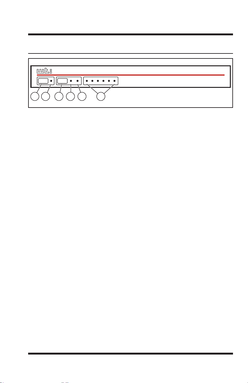
2.1. Front Panel Components
Figure 2.1: Front Panel Components
As shown in Figure 2.1, the CMS-6R4 front panel includes the following
components:
Clear Button: Restarts the CMS-6R4 operating program without
changing user-selected parameters or breaking port connections.
Power Indicator: Lights when power is applied to the unit.
Set Button: The Set Button has two functions; it can either be used as a
manual On/Off switch for the CMS-6R4's four switched outlets, or it can
also be used to initialize the unit to default parameters.
• Manual Switching: To manually switch the outlets Off or On, press
and hold the Set Button for approximately three seconds. Note that
the Manual Switching function can also be disabled as described in
Section 5.5.1.
• Initialization: To initialize the unit to default parameters, press and
hold both the Set and Clear buttons, then release only the Clear Button,
wait for the Activity LEDs to flash, and then release the Set Button.
Notes:
• During initialization, all activity LEDs will flash ON three times.
• When the initialization procedure is performed, all command
selected parameters will be cleared, and the CMS-6R4 will revert to
default parameters.
RDY Indicator: (Ready) Flashes when the unit is ready to receive
commands.
DCD Indicator: Lights when the Data Carrier Detect signal is present.
Activity Indicators: A series of six LEDs, which light to indicate data
activity at the corresponding port.
2-1
Page 12
CMS-6R4 Series - User’s Guide
O
I
PHONE LINE10BaseTACT
SYSTEM
SETUP
PORTS
15 AMPS
MAX
PLUG 1 PLUG 2 PLUG 3 PLUG 4
2
1
3
4
5
6
1
2
3
4
5
6
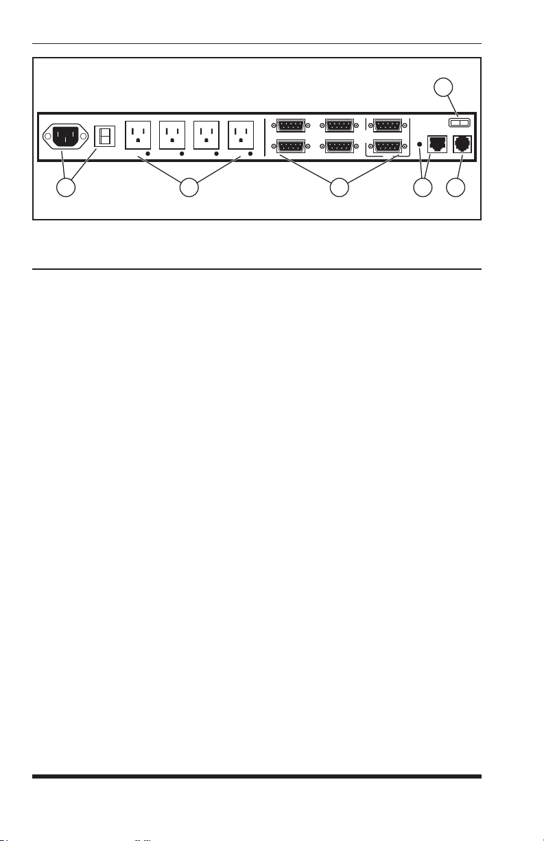
Figure 2.2: Back Panel Components (120 VAC Model Shown)
2.2. Back Panel Components
Power Inlet and Circuit Breaker: An AC inlet and circuit breaker
which supply power to the CMS-6R4. Includes cable keeper (not shown.)
• Model CMS-6R4 (120 VAC): IEC-320-C14, 100 - 120 VAC Power
Inlet, 15 Amp Circuit Breaker.
• Model CMS-6R4-CE (230 VAC): IEC-320-C14, 208 - 240 VAC
Power Inlet, 10 Amp Circuit Breaker.
Switched Plugs and Plug Indicators: Four AC Outlets that can be
switched On, Off, Rebooted or set to user-defined Default values in
response to user commands.
• Model CMS-6R4: Four 100-120 VAC, NEMA 5-15 Outlets with
indicator lights. 15 Amps Total Load.
• Model CMS-6R4-CE: Four 208-240 VAC, IEC-320-C13 Outlets with
indicator lights. 10 Amps Total Load.
Serial RS232 Ports: For connection to console ports on target devices.
Standard DB9 connectors configured as DTE ports, similar to a serial port
on a PC. When connecting a modem, use a standard serial cable. When
connecting a PC or other DTE device use a null modem cable.
Notes:
• Ports 1 is a System Setup Port. In order to ensure local access by
system administrators, Supervisor Level command capability cannot
be disabled at Port 1, and the Port Mode cannot be set to "Buffer" or
"Passive".
• Port 2 can also be used as a Setup Port, providing that the Port Mode
is set to Any-to-Any and the Supervisor Mode is enabled.
2-2
Page 13

Unit Description
10Base-T Port (Network Port): An RJ45 Ethernet Port for connection
to your TCP/IP network. The 10Base-T Port also features an Activity
Indicator flashes to indicate activity at the Network Port. The default
IP Address is 192.168.168.168. For more information on Network Port
configuration, please refer to Section 5.5.2.
Phone Line Port (Internal Modem Port): For connection to your phone
line. For information regarding modem configuration, please refer to
Section 5.5.4.
Main Power Switch: Applies power to the CMS-6R4. This switch must
be "On" in order for the CMS-6R4 to function. Note that this switch is
not used to set the On/Off status of the switched outlets.
2-3
Page 14

CMS-6R4 Series - User’s Guide
2-4
Page 15

3. Quick Start
This Quick Start Guide describes a simplified installation procedure for the
CMS-6R4 hardware, which will allow you to communicate with the unit in
order to demonstrate basic features and check for proper operation.
Note that this Quick Start Guide does not provide a detailed description of
unit configuration, or discuss advanced operating features in detail. For more
information, please refer to the Installation, Configuration and Operation
sections in this User's Guide.
3.1. Hardware Installation
3.1.1. Apply Power to the CMS-6R4
Refer to the safety precautions listed at the beginning of this User's Guide,
and then connect the unit to an appropriate power source. Connect the power
supply cable to the unit’s power inlet, snap the Cable Keeper into place, and
then connect the cable to an appropriate power supply.
Note: The CMS-6R4 is designed for 100 to 120 VAC operation and
the CMS-6R4-CE is designed for 100 to 240 VAC operation.
When power is applied to the CMS-6R4, the ON LED should light, and the
RDY LED should begin to flash. This indicates that the unit is ready to
receive commands.
3.1.2. Connect your PC to the CMS-6R4
The CMS-6R4 can either be controlled by a local PC Serial Port, controlled
via modem, or controlled via TCP/IP network. In order to select parameters,
connect ports or control outlets, commands are issued to the CMS-6R4 via
either the Network Port, Modem Port or a Serial RS232 Port.
• Network Port: Connect the CMS-6R4 10Base-T, half duplex network
interface to your network.
• Serial Port: Use the supplied null modem cable to connect your PC
COM port to Serial Port 1 (The System Setup Port.)
• Modem: Connect your telephone line to the CMS-6R4 Phone Line Port.
3-1
Page 16

CMS-6R4 Series - User’s Guide
3.2. Communicating with the CMS-6R4
The CMS-6R4 offers two separate user interfaces: the Web Browser Interface
and the Text Interface. The Web Browser interface allows you to contact the
unit via a TCP/IP network, using a standard, JavaScript enabled web browser.
The Text Interface consists of a series of ASCII text menus, which may be
accessed via TCP/IP network, Local PC or modem.
Notes:
• When the unit is shipped from the factory, communications
parameters are set as follows: 9600 bps, RTS/CTS Handshaking,
8 Data Bits, One Stop Bit, No Parity. Although the CMS-6R4
allows these parameters to be easily redefined, for this Quick Start
procedure, it is recommended to configure your communications
program to accept the default parameters.
• The CMS-6R4 features a default IP Address (192.168.168.168) and
a default Subnet Mask (255.255.255.0.) This allows initial network
access to command mode without first setting up the unit’s network
parameters (providing that you are contacting the unit from a node
on the same subnet.) When attempting to access the CMS-6R4 from
a node that is not on the same subnet, please refer to Section 5 for
further configuration instructions.
1. Access Command Mode: This procedure differs slightly, depending on
whether you’re contacting the CMS-6R4 via the Web Browser Interface
or Text Interface.
a) Web Browser Interface: Start your JavaScript enabled Web
Browser. Enter the CMS-6R4’s IP address in your browser address
bar and press [Enter].
b) Text Interface:
i. Via Telnet: Telnet to the CMS-6R4’s default IP address.
ii. Via Local PC: Start your communications program and
press [Enter].
iii. Via Modem: Use your communications program to dial the
number for the line that is connected to the CMS-6R4's Phone
Line Port.
3-2
Page 17
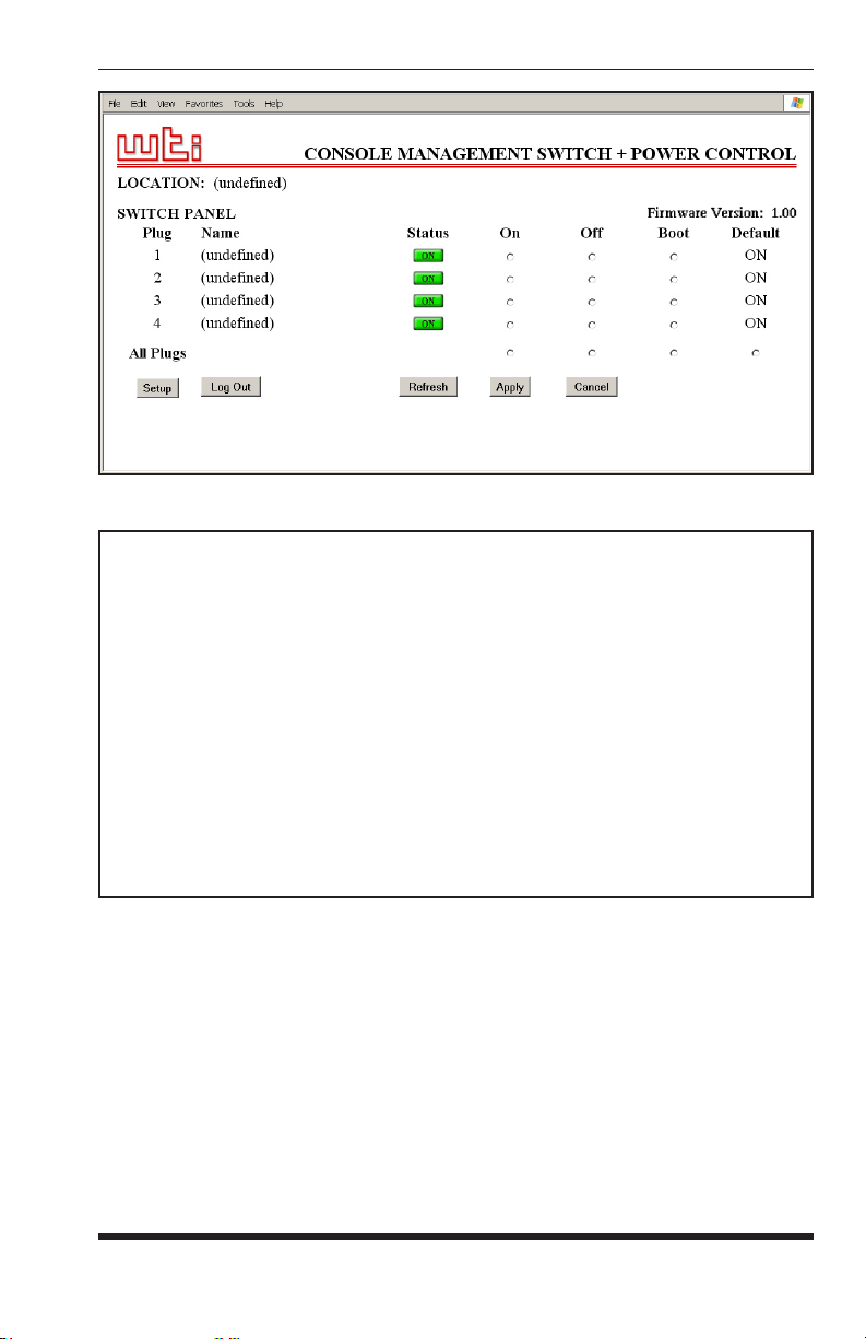
Figure 3.1: Main Status Screen - Web Browser Interface
CMS-6R4 v1.00 Site ID: (undefined)
PORT | NAME | CMD ACCESS | STATUS | MODE | BUFFER COUNT
-----+------------------+----------------+--------+---------+--------------+
1 | (undefined) | Unlocked | Free | Any | 0 |
2 | (undefined) | Unlocked | Free | Any | 0 |
3 | (undefined) | Unlocked | Free | Any | 0 |
4 | (undefined) | Unlocked | Free | Any | 0 |
5 | (undefined) | Unlocked | Free | Any | 0 |
6 | (undefined) | Unlocked | Free | Any | 0 |
7 | (undefined) | Unlocked | Free | Modem | 0 |
-----+------------------+----------------+--------+---------+--------------+
PLUG | NAME | BOOT/SEQ DELAY | STATUS | DEFAULT |
-----+------------------+----------------+--------+---------+
1 | (undefined) | 0.5 Secs | ON | ON |
2 | (undefined) | 0.5 Secs | ON | ON |
3 | (undefined) | 0.5 Secs | ON | ON |
4 | (undefined) | 0.5 Secs | ON | ON |
-----+------------------+----------------+--------+---------+
“/H” for help.
CMS>
Figure 3.2: Main Status Screen - Text Interface
Quick Start
2. Password Prompt: Normally at this point, no user accounts have been
defined yet, so if the password prompt is displayed, you can simply
press [Enter] or click "OK" to bypass the prompt. However, if you have
previously defined one or more passwords, enter the username (Web
Interface only) and password and then press [Enter] or click "OK." The
Status Screen should be displayed as shown in Figure 3.1 or 3.2.
3-3
Page 18

CMS-6R4 Series - User’s Guide
3.3. Connecting Ports and Switching Outlets
Although both the Text Interface and Web Browser Interface allow you
to select configuration parameters, the Text Interface is always used when
invoking commands to create connections between ports. Although the Web
Browser Interface does allow access to outlet switching functions, for this
Quick Start procedure, it is recommended to perform the following steps via
the Text Interface. If you have previously accessed command mode via the
Web Browser Interface, exit command mode (log out), then re-enter command
mode using the Text Interface as described in Step 1 in Section 3.2.
Proceed as follows to connect ports and switch outlets:
1. Review the Help Menu: At the Text Interface command prompt, type
/H and press [Enter] to display the Help Menu, which provides a basic
listing of all available CMS-6R4 commands.
2. Creating Connections Between Ports: The CMS-6R4 can perform two
different types of port connections; Resident Connections and Third Party
Connections:
a) Resident Connection: Your resident port issues a /C command to
connect to a second port.
i. To connect your resident port to Port 3, type /C 2 [Enter].
While you are connected to Port 3, the unit will not recognize
additional commands issued via your resident port. However,
the unit will recognize a Resident Disconnect Sequence issued
at either connected port.
ii. Issue the Resident Disconnect Sequence (Logoff Sequence);
type ^X (press [Ctrl] and [X] at the same time).
b) Third Party Connection: Your resident port issues a /C command
to create a connection between two other ports.
i. To connect Port 3 to Port 4, type /C 3 4 [Enter].
ii. While Ports 3 and 4 are connected, your resident port will still
recognize commands. Type
Screen. The "STATUS" column should now list Ports 3 and 4
as connected and the other ports as "Free".
iii. Issue a Third Party Disconnect command; type /D 3 [Enter].
The unit will display the "Are you Sure (y/n)?" prompt. Type
and press [Enter] to disconnect.
iv. Type /S [Enter] to display the Status Screen. The "STATUS"
column should now list Ports 3 and 4 as "Free".
3-4
/S [Enter] to display the Status
y
Page 19

Quick Start
3. Controlling Outlets: You may wish to perform the following tests in
order to make certain that the switched outlets are functioning properly.
a) Reboot Outlet: At the command prompt, type /BOOT 1 and press
[Enter]. The status indicator for Plug 1 should go Off, pause for a
moment and then go back On, indicating that the boot cycle has been
successfully completed.
b) Switch Outlet Off: At the command prompt, type /OFF 1 and
then press [Enter]. The status indicator for Plug 1 should go Off,
indicating that the command has been successfully completed.
Leave Plug 1 in the "Off" state, and then proceed to the next step.
c) Switch Outlet On: At the command prompt, type /ON 1 and press
[Enter]. The status indicator for Plug 1 should then go back On,
indicating that the command has been successfully completed.
4. Exit Command Mode: To exit command mode, type /X and press
[Enter]. When the "Sure" prompt is displayed, type Y and press [Enter].
This completes the Quick Start instructions for the CMS-6R4. Prior to placing
the unit into operation, it is recommended to refer to the remainder of this
user’s guide for important information regarding advanced configuration
capabilities and more detailed operation instructions.
3-5
Page 20

CMS-6R4 Series - User’s Guide
3-6
Page 21

4. Installation
This Section provides further details regarding installation of the CMS-6R4.
4.1. Power Supply Connection
Use the supplied power cord to connect the CMS-6R4 to an appropriate power
supply. Note that the CMS-6R4's Main Power switch must be "On" in order
for the unit to operate.
CAUTIONS:
• Before attempting to install this unit, please review the warnings
and cautions listed at the front of the user's guide.
• This device should only be operated with the type of power
source indicated on the instrument nameplate. If you are not
sure of the type of power service available, please contact your
local power company.
• Reliable earthing (grounding) of this unit must be maintained.
Particular attention should be given to supply connections when
connecting to power strips, rather than directly to the branch
circuit.
4.1.1. Installing the Cable Keeper
The CMS-6R4 includes a cable keeper, which is designed to prevent the power
supply cable from being accidentally disconnected from the unit.
When attaching the power supply cable to the unit, first swing the cable keeper
out of the way, then plug the power cable securely into the power input. When
the cable is in place, snap the cable keeper over the plug to secure the cable to
the unit.
4.2. Connecting Devices to the Switched Outlets
Connect the power cord from your switched device to a switched AC Outlet on
the CMS-6R4 back panel. Note that when power is applied to the CMS-6R4,
the Switched AC Outlets will be switched "ON". Note that the CMS-6R4
(120 VAC Model) is designed for 100 to 120 VAC operation and will support
up to 15 Amps maximum, and the CMS-6R4-CE (230 VAC Model) is designed
for 100 to 240 VAC operation and will support up to 10 Amps maximum.
4-1
Page 22

CMS-6R4 Series - User’s Guide
4.3. Connecting Devices to the RS232 Serial Ports
The six, serial RS232 Ports on the CMS-6R4 back panel are standard DB9
connectors, configured as DTE Ports, and are similar to a standard serial port
on a PC. Note that Port 1 is designated as a System Set Up Port, and that in
order to ensure that this port is always accessible by system administrators, the
Supervisor Mode cannot be disabled at Port 1. For a description of the RS232
Port interface, please refer to Appendix A.
Use a DB9 cable to connect the RS232 serial port on your device to the RS232
serial port on the CMS-6R4 back panel. When connecting external modems
and other DCE devices, use a standard serial modem cable. When connecting
PCs and other DTE devices, use a standard null modem cable.
4.4. Connecting Control Devices to the CMS-6R4
The CMS-6R4 can be controlled and configured via local serial connection, or
controlled remotely via modem or TCP/IP network connection.
4.4.1. Control via Local PC
Use the supplied null modem cable to connect your PC COM port to one of the
CMS-6R4's two RS232 System Setup Ports. The System Setup Ports are male,
RS232C DB9 connectors, wired in a DTE configuration. In the default state,
the Setup Ports are configured for 9600 bps, no parity, 8 data bits, 1 stop bit.
4.4.2. Control via Modem
Connect your telephone line to the Phone Line port on the CMS-6R4 back
panel. If necessary, configure the Modem Port as described in Section 5.5.4.
4.4.3. Connecting the Network Cable
The Network Port is an RJ45 Ethernet jack, for connection to a TCP/IP
network. Connect your 10Base-T cable to the Network Port. Note that the
CMS-6R4 includes a default IP address (192.168.168.168) and a default subnet
mask (255.255.255.0.) When installing the CMS-6R4 in a working network
environment, it is recommended to define network parameters as described in
Section 5.5.2.
Note: The CMS-6R4 features a 10Base-T network interface. When
connecting to a 100Base-T interface, most router switches will
autosense to determine if the device is 100Base-T or 10Base-T,
and then configure the network interface accordingly. If your
router switch does not autosense, the network interface port must be
manually set to 10Base-T.
This completes the CMS-6R4 installation instructions. Please proceed to the
next Section for instructions regarding unit configuration.
4-2
Page 23

5. Configuration
5.1. Supervisor Mode and Non-Supervisor Mode
In order to restrict access to sensitive command functions, the CMS-6R4
features two operating modes; Supervisor Mode and Non-Supervisor Mode.
• Supervisor Mode: Allows access to all configuration menus, switching
functions and status screens. The Supervisor Mode status screens show
On/Off conditions for all serial ports and switched outlets, and list all
currently defined system parameters.
• Non-Supervisor Mode: Allows access to port connection, switching and
reboot commands, but does not allow access to configuration functions.
Non-Supervisors may only issue commands to, or view status of the ports
and plugs that are specifically allowed by their password/account.
The CMS-6R4 will display a password prompt when the unit is contacted
via the COM Port or Network Port. The password entered at this prompt
determines whether the unit will start-up in Supervisor Mode or NonSupervisor Mode. If the password allows access to Supervisor Mode, then
the Supervisor Mode will be active. If the password does not permit access
to Supervisor Mode, then the Non-Supervisor Mode will be active. The
process of defining passwords and granting Supervisor rights is discussed in
Section 5.4 and Section 5.5.1.1.
Notes:
• If you wish to restrict access to configuration menus, you must
create at least one password that permits access to Supervisor Mode.
• If you do not create at least one password that permits access to
Supervisor Level commands, then the CMS-6R4 will always startup in Supervisor Mode, allowing unprotected access to configuration
and switching functions.
• If you do not create at least one password that permits Supervisor
Level commands, then the Password Prompt will not be displayed
when you access the CMS-6R4 command mode.
• When the CMS-6R4 is contacted via the Web Interface, the
password prompt will also include a field for the user name. The
user name prompt is not displayed when the unit is contacted via the
Text Interface.
5-1
Page 24

CMS-6R4 Series - User’s Guide
5.2. Communicating with the CMS-6R4
In order to configure the unit or invoke command functions, you must first
connect to the CMS-6R4 and access command mode. As discussed in
Section 3, the CMS-6R4 offers two separate command interfaces: the Web
Browser Interface, and the Text Interface.
The CMS-6R4 also offers three different methods for accessing command
mode; via network, via external modem, or via local PC. The Web Browser
Interface is only available when the CMS-6R4 is contacted via network, and
the Text Interface is available via network, modem or local PC. The sections
that follow describe the procedure for accessing the Web Browser Interface or
Text Interface.
Note: Configuration functions are only available when you have
logged into the CMS-6R4 command mode using a password that
permits access to the Supervisor Mode.
5-2
Page 25
Confi guration
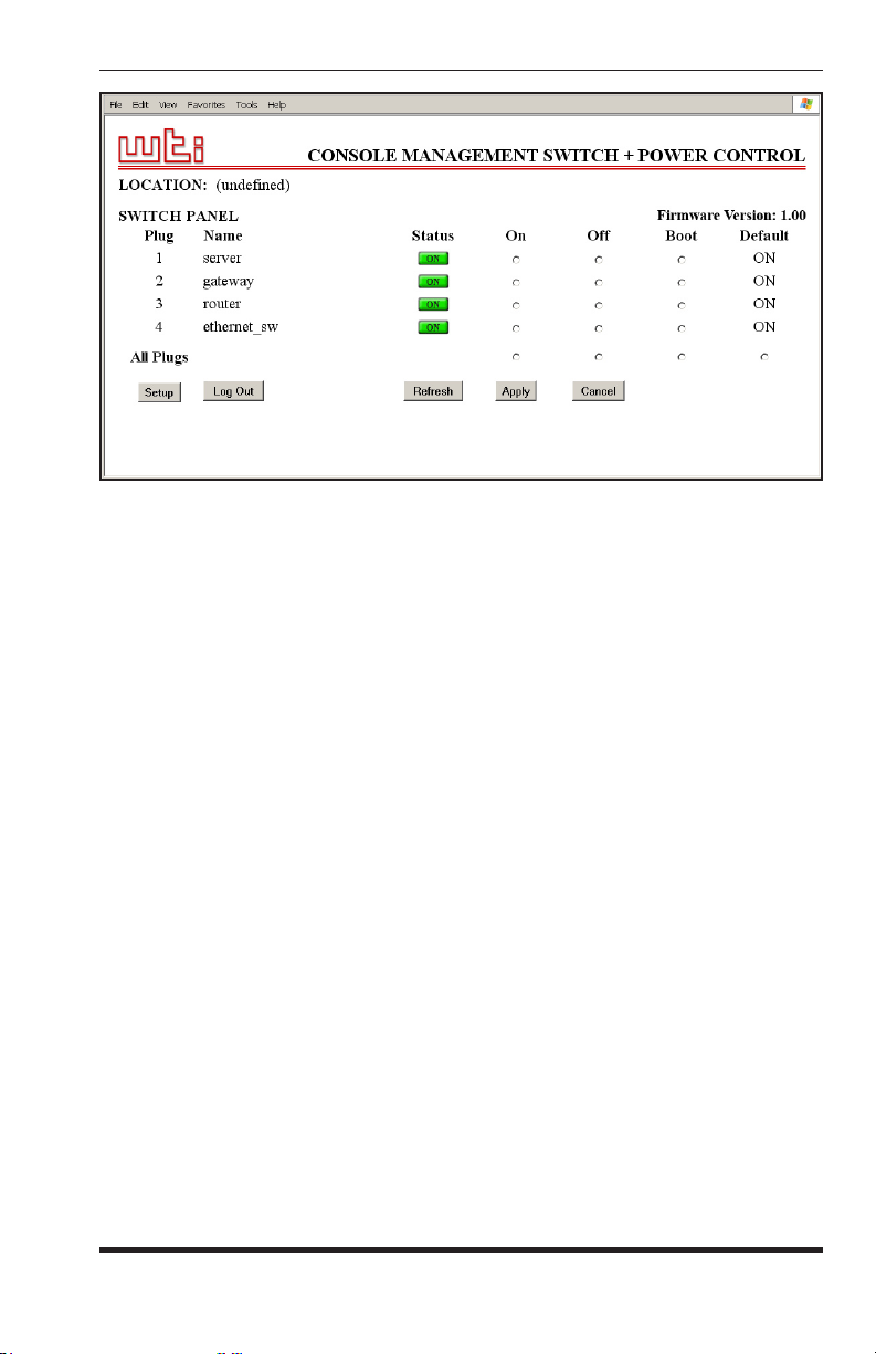
Figure 5.1: Main Status Screen - Web Browser Interface (Sample Values Shown)
5.2.1. Accessing the Web Browser Interface
In order to use the Web Browser Interface, the CMS-6R4 must be connected
to a TCP/IP network, and your PC must be equipped with a JavaScript enabled
web browser (such as Internet Explorer or Netscape® Navigator.)
1. Start your JavaScript enabled Web Browser.
2. Key the CMS-6R4’s IP address (default = http://192.168.168.168) into the
web browser’s address bar, and then press [Enter].
3. Password Prompt: The CMS-6R4 will display a prompt, which asks
for your name and password. Key in a password that permits access to
Supervisor Level commands, and then press [Enter] (Text Interface) or
click on "OK" (Web Browser Interface.) Note that the password prompt
will only be displayed if you have previously defined a password/account
that permits access to Supervisor Level Commands.
If a valid password is entered, the Main Status Screen will appear as shown in
Figure 5.1.
5-3
Page 26

CMS-6R4 Series - User’s Guide
CMS-6R4 v1.00 Site ID: (undefined)
PORT | NAME | CMD ACCESS | STATUS | MODE | BUFFER COUNT
-----+------------------+----------------+--------+---------+--------------+
1 | (undefined) | Unlocked | Free | Any | 0 |
2 | (undefined) | Unlocked | Free | Any | 0 |
3 | (undefined) | Unlocked | Free | Any | 0 |
4 | (undefined) | Unlocked | Free | Any | 0 |
5 | (undefined) | Unlocked | Free | Any | 0 |
6 | (undefined) | Unlocked | Free | Any | 0 |
7 | Internal_Modem | Unlocked | Free | Modem | 0 |
-----+------------------+----------------+--------+---------+--------------+
PLUG | NAME | BOOT/SEQ DELAY | STATUS | DEFAULT |
-----+------------------+----------------+--------+---------+
1 | (undefined) | 0.5 Secs | ON | ON |
2 | (undefined) | 0.5 Secs | ON | ON |
3 | (undefined) | 0.5 Secs | ON | ON |
4 | (undefined) | 0.5 Secs | ON | ON |
-----+------------------+----------------+--------+---------+
“/H” for help.
CMS>
Figure 5.2: Main Status Screen - Text Interface
5.2.2. Accessing the Text Interface
The Text Interface can be accessed via Network, modem or local PC. In order
to access the Text Interface, your installation must include the following:
• Access Via Network: The CMS-6R4 must be connected to your TCP/IP
Network, and your PC must include a communications program (such as
Hyperterminal™.)
• Access Via Modem: A phone line must be connected to the CMS-6R4's
Modem Port. Your PC Must include a communications program (such as
Hyperterminal™.)
• Access Via Local PC: Your local PC must be connected to a CMS-6R4
RS232 COM Port. The local PC must include a communications program
(such as Hyperterminal™.)
To access command mode via the Text Interface, proceed as follows:
1. The CMS-6R4 is transparent to parity and will accept 7 or 8 bit
characters, but will always answer back at 8 bits, no parity. Make certain
your communication program is set for the appropriate baud rate, bits,
parity and Communications Port.
a) Via Modem: Start your communications program. Dial the number
for the line connected to the CMS-6R4's Phone Line port. Wait for
the Connect message, then proceed to Step 2.
b) Via Local PC: Start your communications program and press
[Enter]. Wait for the connect message, then proceed to Step 2.
5-4
Page 27

Confi guration
c) Via Network: The CMS-6R4 includes a default IP address
(192.168.168.168), which allows you to contact the unit from any
network node on the same subnet. When the CMS-6R4 is installed
in a working network environment, it is recommended to redefine
the IP Address, Subnet Mask, and Gateway Address as described in
Section 5.5.2.
i. Telnet to the CMS-6R4’s IP address. For example, if the IP
address is "192.168.168.168", then on a UNIX system, the
Telnet command would be:
$ telnet 192.168.168.168 [Enter]
ii. If the Telnet connection is refused, this may mean that
either the IP Security feature has denied the connection (See
Section 5.5.2.1), or that the unit is operating on a 100Base-T
network that does not autosense for 10Base-T devices (see
Section 4.4.3.)
2. Password: If you have not yet created a password that permits access to
Supervisor Mode, the password prompt will not be displayed when the
unit is accessed via the Text Interface.
a) If a password that permits access to Supervisor Mode has been
defined, the unit will display the Password Prompt. Key in a
password that permits access to Supervisor Mode, and press [Enter].
b) Note that the Password feature is case sensitive.
3. If a valid password is entered, the CMS-6R4 will display the Status
Screen shown in Figure 5.2, followed by the "CMS>" Command Prompt.
5.3. System SetUp Port
Port 1 is designated as a System SetUp Port, and will therefore, always
permit access to Supervisor Mode. In order to ensure that access to command
functions is always available, the Supervisor Mode cannot be disabled at
Port 1, and the Port Mode for Port 1 cannot be set to "Buffer" or
"Passive" mode.
Note: Port 2 can also function as a Setup Port, providing that the Port
Mode is set to "Any-to-Any" or "Modem", and the Supervisor Mode
is enabled.
5-5
Page 28

CMS-6R4 Series - User’s Guide
5.4. Password Functions
The CMS-6R4's password directory allows you to define up to 32 passwords.
These passwords are not only used to protect access to the CMS-6R4 unit, but
are also used to determine the type of commands that each user will be allowed
to invoke, and the ports and switched outlets that each user will be allowed to
control.
Passwords that have access to Supervisor Mode are allowed to change
configuration parameters and may connect to any CMS-6R4 port and switch
any CMS-6R4 outlet. On the other hand, passwords which are denied access
to Supervisor Mode are not allowed to change configuration parameters, and
are restricted to the ports and outlets specifically allowed by that password.
The password directory feature is described in greater detail in Section 5.5.1.1.
Note that once you have defined at least one password that permits access to
Supervisor Mode, the CMS-6R4 will display a password prompt whenever
you attempt to access command mode. Supervisor Level commands are
summarized in Section 10.2 of this User’s Guide.
Notes:
• If you do not define at least one password that permits access
to Supervisor Mode, then Supervisor Level commands will be
available to all ports, and port access and configuration functions
will not be password protected.
• If you wish to restrict users from changing CMS-6R4 configuration
parameters or connecting to restricted ports, you must define at least
one password that permits access to Supervisor Mode as described
in Section 5.5.1.1.
• If the unit is reset to default parameters, all passwords will be
erased, and Supervisor Level commands will be available at all
ports, without password protection.
Note that if you wish to completely deny a given port’s access to Supervisor
Mode (even with a Supervisor password), the Port Parameters menus (/P) can
be used to disable the Supervisor Mode at the Network Port and at any RS232
Port except for Port 1 (the System SetUp Port.)
5-6
Page 29

Confi guration
5.5. Configuration Menus
As described in the sections that follow, configuration parameters can be
selected via the Web Browser Interface or Text Interface. Although the
Web Browser and Text Interface provide two separate means for selecting
parameters, both interfaces allow access to essentially the same set of
parameters, and parameters selected via one interface will also be applied to
the other.
Web Browser Interface:
configuration menus; a row of buttons will be displayed along the left hand
edge of the screen. Note the following:
• Newly selected parameters will not be activated until you click the
"Apply" button.
• Click "Switch Panel" to return to the main status screen.
Text Interface:
command to access the desired menu. Note the following:
• To exit from a parameters menu, press the [Esc] key.
The following sections describe options and parameters that can be accessed
via each of the configuration menus.
Note: Configuration menus are only available when the Supervisor
Mode is active. Configuration menus are not available if you have
logged in using a password that does not permit access to Supervisor
Level commands.
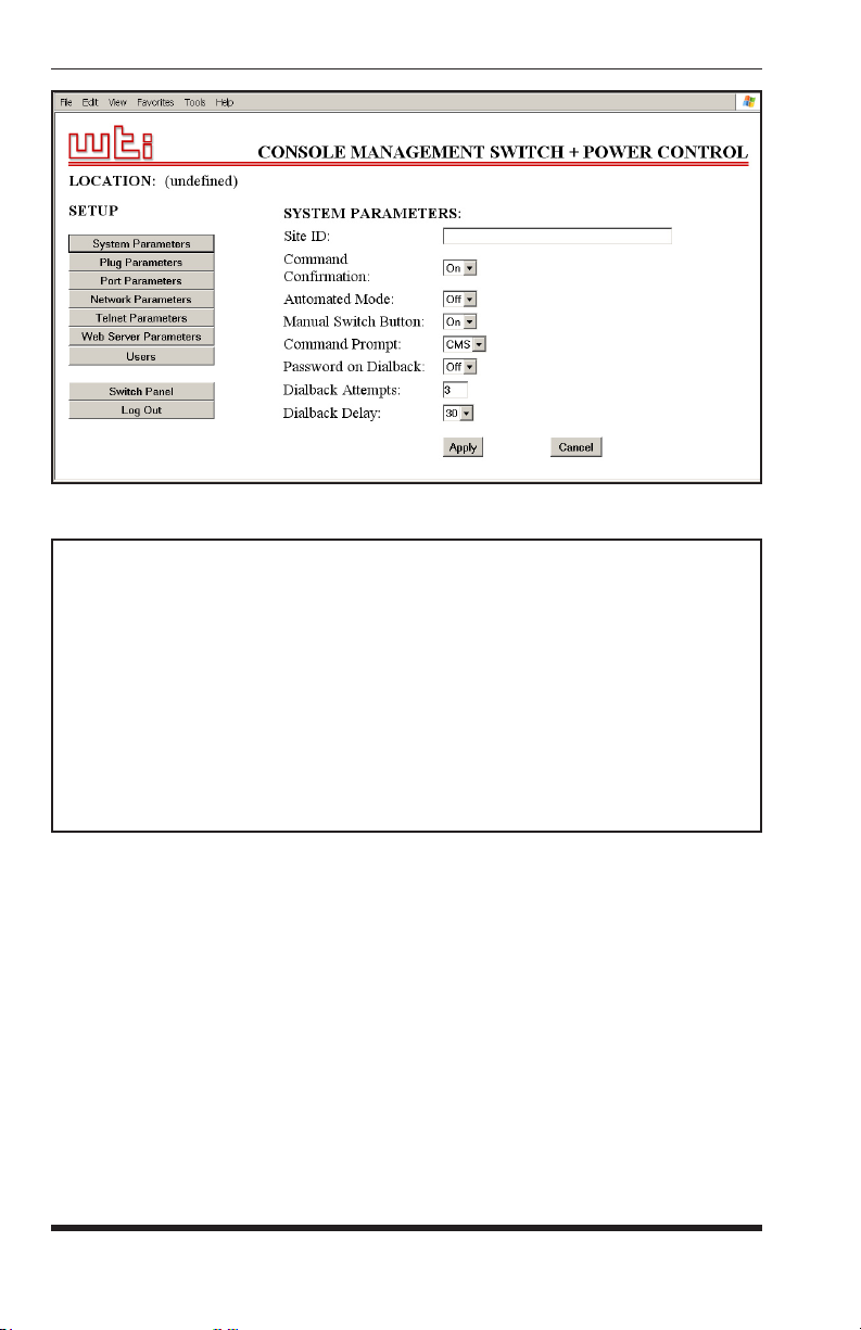
5.5.1. The System Parameters Menu
The System Parameters Menus allow you to select parameters such as the
Site I.D. Message, Command Confirmation and other options and, in the Text
Interface it is also used to create passwords/accounts (In the Web Browser
Interface, passwords are created via the "Users" button in the Setup Menu.
Refer to the Help Screen (/H), then enter the appropriate
Click the "Setup" button to gain access to the
• Web Browser Interface: Click the "Setup" button to access the Setup
Menus, and then click the "System Parameters" button. The System
Parameters Menu will be displayed as shown in Figure 5.3.
• Text Interface: Type /F and press [Enter]. The System Parameters
Menu will be displayed as shown in Figure 5.4.
5-7
Page 30
CMS-6R4 Series - User’s Guide
Figure 5.3: System Parameters Menu - Web Browser Interface
SYSTEM PARAMETERS:
1. Site ID: (undefined)
2. Command Confirmation: On
3. Automated Mode: Off
4. Manual Switch Button: On
5. Command Prompt: CMS
6. Password on Dial Back: Off
7. Dial Back Attempts: 3
8. Dial Back Delay: 30 Secs
9. Create/Edit user password
Enter Selection,
Press <ESC> to Exit ...
Figure 5.4: System Parameters Menu - Text Interface
5-8
Page 31

Confi guration
The System Parameters Menus allow you to define the following parameters:
• Site ID: Defines a brief text message, which can describe the location or
function of the CMS-6R4 unit. (Up to 32 characters,
Default = undefined.)
Notes:
• The Site ID Message cannot begin with a forward slash (/) or
backslash (\) character.
• The Site ID Message cannot include non printable characters or
quotation marks.
• Command Confirmation: When enabled, the CMS-6R4 will display
a confirmation prompt before executing certain commands. When
disabled, the prompt will be suppressed and commands will be executed
immediately. (Default = On/Enabled.)
• Automated Mode: When enabled, the CMS-6R4 will execute port
connection/disconnection, switching, reboot and exit commands without
displaying a confirmation prompt, status screen or confirmation messages.
For more information, please refer to Section 6.5. (Default = Off.)
Note: When this option is enabled, security functions are suppressed,
and users are able to access configuration menus and control plugs
without entering a password. If security is a concern and the
Automated Mode is required, it is recommended to use the IP Security
feature (Section 5.5.2.1) to restrict access.
• Manual Switch Button: Enables/disables the Set Button's manual
plug control function, but does not effect the Set Button's ability to reset
parameters to default values. (Default = "On".)
▪ Off: Disables the manual plug control function.
▪ On: Enables manual plug control. When pressed and held for three
seconds, all outlets will be toggled On or Off.
• Command Prompt: Allows the Text Interface command prompt to be
set to either "CMS", "NPS", "IPS" or "NBB." (Default = CMS.)
• Password on Dial Back: Enables/Disables the "Password on Dial Back"
feature as described in Section 5.5.1.6. (Default = Off.)
• Dial Back Attempts: Sets the number of times that the CMS-6R4
will attempt to call the dial back number when the Dial Back feature is
properly configured and enabled, and you attempt to access command
mode via Modem. For more information on the Dial Back feature, please
refer to Section 5.5.1.6. (Default = 3.)
5-9
Page 32

CMS-6R4 Series - User’s Guide
• Dial Back Delay: Sets the amount of time that will elapse between Dial
Back Attempts. For more information on the Dial Back Feature, please
refer to Section 5.5.1.6. (Default = 30 Seconds.)
• Edit Password Directory: Provides access to a series of menus that
are used to create, edit, and delete passwords/accounts as described in
Section 5.5.1.1.
5.5.1.1. The Password Directory
In addition to defining passwords and assigning command privileges to each
password, the Edit Password Directory function allows you to determine which
ports and switched outlets each password will be allowed to control, and also
configures Dial Back parameters. The Password Directory allows for the
definition of up to 32 separate passwords.
Note:
• The Password Directory menu is only available when you have
logged into command mode using a password that permits access to
Supervisor Mode.
• In the Text Interface, the /V command can be invoked to view the
Password Directory.
To activate the Edit Password Directory menu, proceed as follows:
• Web Browser Interface: Click the "Setup" button to access the Setup
Menus, and then click the "Users" button. The Password Directory Menu
will be displayed as shown in Figure 5.5.
• Text Interface: First, type /F and press [Enter] to access the System
Parameters Menu (Figure 5.4.) At the System Parameters Menu, type
and press [Enter] to display the Password Directory Menu (Figure 5.6.)
9
The Password Directory Menu offers the following options:
• View Password Directory: Displays a summary of currently defined
user accounts. Note that actual passwords will not be displayed, and
when configuring the system via the Text Interface, the Password
Directory is displayed by invoking the /V command and is not present on
the Password Directory menu.
• Add Name/Password (Create Users): Creates new passwords and
assigns Supervisor Mode access and port access rights as described in
Section 5.5.1.2.
5-10
Page 33

Figure 5.5: The Password Directory Menu (Web Browser Interface)
EDIT PASSWORD DIRECTORY:
1. Add Name/Password
2. Edit/Delete from List
3. Edit/Delete from Search
4. Delete Entire Directory
Enter: #<CR> to select,
<ESC> for previous menu ...
Figure 5.6: The Password Directory Menu (Text Interface)
Confi guration
• Edit Users (Modify Users): Allows you to change assigned passwords
and port and plug rights for each account. When configuring the unit
via the Text Interface, users accounts are edited via the "Edit from List"
or "Edit from Search" functions; when configuring the unit via the Web
Browser Interface, accounts are edited via either the "Search Users" or
"Modify Users" functions as described in Section 5.5.1.3.
• Deleting Users: Allows you to delete existing user accounts. When
configuring the unit via the Text Interface, user accounts are deleted
using the "Delete from List" or "Delete from Search" functions; when
configuring the unit via the Web Browser Interface, accounts are deleted
using the "Delete Users" functions as described in Section 5.5.1.4.
• Delete Entire Directory: Clears the password directory, and deletes all
existing passwords as described in Section 5.5.1.5. When configuring
the unit via the Text Interface, this function is accessed via item 4 "Delete
Entire Directory" in the Password Directory Menu; when configuring the
unit via the Web Interface, this function is accessed via the "Delete Users"
menu, using the "Delete All" button.
5-11
Page 34

CMS-6R4 Series - User’s Guide
5.5.1.2. Adding Passwords
The "Add Name/Password" menu (Text Interface) and "Create User" menu
(Web Browser Interface) are used to create new user accounts and add
passwords to the password directory. To create new passwords/accounts,
proceed as follows:
• Web Browser Interface: Click the "Setup" button to access the Setup
Menus, and then click the "Users" button. From the Password Directory
Menu, click the "Create Users" button to define new user accounts. The
Create User Menu will be displayed as shown in Figure 5.7.
• Text Interface: First, type /F and press [Enter] to access the System
Parameters Menu (Figure 5.4.) At the System Parameters Menu, type
and press [Enter] to display the Password Directory Menu (Figure 5.6),
then type 1 and press [Enter] to access the Add Name/Password menu as
shown in Figure 5.8.
The Add Name/Password Menu allows you to assign the following parameters:
• Name: Assigns a username to the password. Note that usernames are
only required when logging into command mode via the Web Browser
Interface. (Default = undefined.)
• Password: After initially keying in the password, you will need to enter
the password a second time in order to verify that it is correct.
(Default = undefined.)
9
• Dial Back #: Defines the number that the CMS-6R4 will dial when the
Dial Back feature is enabled and the unit is contacted via modem. For
more information on the Dial Back Mode, please refer to Section 5.5.1.6.
(Default = undefined.)
• Dial Back Mode: Enables/Disables the Dial Back Mode for this
password. For more information on the Dial Back Mode, please refer to
Section 5.5.1.6. (Default = Off.)
• Supervisor Mode: Enables/Disables Supervisor Mode for this password.
When Supervisor Mode is enabled, the password will provide access
to all configuration menus, and allow connections to all ports. When
Supervisor Mode is disabled, the password will not permit access to
configuration menus, and will only allow access to ports specifically
permitted by the password. (Default = Off.)
Note: In order to access Supervisor Mode from any given port,
the port at which the password is issued must also permit Supervisor
Commands.
5-12
Page 35

Confi guration
Figure 5.7: The Create Name/Password Menu (Web Browser Interface)
ADD NAME/PASSWORD:
1. Name: (undefined)
2. Password: (undefined)
3. Dial Back #: (undefined)
4. Dial Back Mode: Off
5. Supervisor Mode: Off
6. Port Access: None
7. Plug Access: None
8. Save Entry
Enter: #<CR> to select,
<ESC> for previous menu ...
Figure 5.8: The Add Name/Password Menu (Text Interface)
5-13
Page 36

CMS-6R4 Series - User’s Guide
• Port Access: Determines which ports this password will be allowed to
create connections with. (Default = none.)
Notes:
• Several different passwords/accounts can be allowed to create
connections to the same port.
• When selecting ports via the text interface, key in the number for the
desired port and then press [Enter]. To select additional ports, enter
the number for each corresponding port. Note that each port number
selected must be followed by the [Enter] key.
• Plug Access: Determines which Plugs (Outlets) this password will be
allowed to control. (Default = none.)
Notes:
• Several different passwords/accounts can be allowed access to the
same outlets.
• When selecting outlets via the text interface, key in the number for
the desired outlet and then press [Enter]. When selecting additional
outlets, each outlet number selected must be followed by
the [Enter] key.
• Save Entry: (Text Interface Only) Note that if you exit from the menu
without first saving, the password and account information will not be
saved. In the Web Browser Interface, passwords are saved when you
press the "Apply" button
5-14
Page 37

Confi guration
5.5.1.3. Editing Passwords
This function is used to edit existing user accounts, and allows you to change
passwords, dialback parameters, plug access and port access for each user
account. To edit existing passwords, proceed as follows:
• Web Browser Interface: Click the "Setup" button to access the Setup
Menus, and then click the "Users" button. From the Password Directory
Menu, click either the "Modify Users" button or the "Search Users"
button and then select the desired user(s) from the resulting submenu.
• Text Interface: First, type /F and press [Enter] to access the System
Parameters Menu (Figure 5.4.) At the System Parameters Menu, type
9
and press [Enter] to display the Password Directory Menu (Figure 5.6.)
At the Password Directory Menu, either type 2 and press [Enter] to
select the password from a list, or type 3 and press [Enter] to select the
password using the search function.
Once you have selected the desired account, the Edit Users Menu will be
displayed. The Edit Users Menu provides access to the same options that are
present in the "Add Users" menu, discussed in Section 5.5.1.2.
Note: After you have edited a user account, is important to always
save the account before exiting the Edit Users menu; if the account is
not saved, then the edited account information will be discarded when
you exit from the menu.
5-15
Page 38

CMS-6R4 Series - User’s Guide
5.5.1.4 Deleting Passwords
This function is used to delete existing user accounts. To delete existing
passwords/accounts, proceed as follows:
• Web Browser Interface: Click the "Setup" button to access the Setup
Menus, and then click the "Users" button. From the Password Directory
Menu, click the "Delete Users" button, then select the desired user(s) from
the resulting menu and click the "Delete" button.
• Text Interface: First, type /F and press [Enter] to access the System
Parameters Menu (Figure 5.4.) At the System Parameters Menu, type
and press [Enter] to display the Password Directory Menu (Figure 5.6.)
At the Password Directory Menu, either type 2 and press [Enter] to
select the password from a list, or type 3 and press [Enter] to select
the password via the search function. When the account information is
displayed, type 9 and press [Enter] to delete the selected account.
Note: Deleted accounts cannot be automatically restored.
5.5.1.5. Deleting the Entire Password Directory
The Edit Password Directory menu can also be used to delete the entire
password directory, rather than accessing each individual password and
deleting them one at a time. To delete the Password Directory and clear all
passwords, proceed as follows:
• Web Browser Interface: Click the "Setup" button to access the Setup
Menus, and then click the "Users" button. From the Password Directory
Menu, click the "Delete Users" button. When the Delete User's menu
appears, click the "Delete All" button.
• Text Interface: First, type /F and press [Enter] to access the System
Parameters Menu (Figure 5.4.) At the System Parameters Menu, type
and press [Enter] to display the Password Directory Menu (Figure 5.6.)
At the Password Directory Menu, type 4 and press [Enter] to delete all
currently defined user accounts.
9
9
Notes:
• Deleted passwords cannot be recovered.
• If the Password Directory is deleted, the password prompt will no
longer be displayed, and users will be able to access Supervisor
Mode without a password. In order to restrict access to Supervisor
commands, you must define at least one password that specifically
permits access to Supervisor Mode.
5-16
Page 39

Confi guration
5.5.1.6. The Dial Back Function
The Dial Back Function provides an additional layer of security when callers
attempt to access command mode via modem. When this function is properly
configured, callers will
not be granted immediate access to command mode
upon entering a valid password; instead, the unit will disconnect, and dial a
user-defined number before allowing access via that number. If desired, users
may also be required to re-enter the password after the CMS-6R4 dials back.
Note that a separate Dial Back Number can be defined for each password, and
the feature may also be independently enabled for each password. To enable
this function, proceed as follows:
1. Access command mode using a port and password that permit access
to Supervisor Mode, and then access the System Parameters Menu as
described in Section 5.5.1.
2. System Parameters Menu: Note that dial back parameters selected
via this menu are global, and will apply to all passwords. Define the
following parameters:
• Password on Dial Back: (Optional) Determines whether or not the
Dial Back Mode will require the answering party to re-enter their
password after a Dial Back is performed.
• Dial Back Attempts: The number of times the CMS-6R4 will attempt
to call the dial back number.
• Dial Back Delay: The amount of time the CMS-6R4 will wait
between Dial Back attempts.
3. Edit Password Directory: Access the Password Directory menu as
described in Section 5.5.1.1. From this menu, you may either define new
passwords that use the Dial Back Function, or alter existing passwords
to include the Dial Back Function. The following parameters should be
defined for each password that will use the Dial Back function:
• Dial Back #: The number that will be called when a Dial Back is
performed. This is the number for the password owner’s modem.
• Dial Back Mode:
Enables/Disables the Dial Back function for this
password. When enabled, this password will require a dial back to
be performed before allowing access, whenever this password user
attempts to access the unit via modem.
Note: In order for new parameters to be saved, you must either Save
the Password (Text Interface) or apply the password (Web Browser
Interface) before leaving the menu.
5-17
Page 40

CMS-6R4 Series - User’s Guide
Dial Back Example:
Assume that the unit is configured as follows:
System Parameters Menu:
• Password on Dial Back:
• Dial Back Attempts:
• Dial Back Delay:
On
3
30 Seconds
User Account Parameters:
• Name: Test1
• Password:
• Dial Back #:
• Dial Back Mode:
test1
5551234
On
Given this configuration, the unit would behave as follows :
1. Password "test1" Entered at Modem Port: Unit confirms that
password is valid, then disconnects.
2. Dial Back: Unit dials "555-1234" (the Dial Back Number for "test1")
and waits for the user’s remote modem to answer.
3. Password on Dialback: When the modem at the Dial Back Number
answers, the CMS-6R4 will prompt the user to re-enter the password
before allowing access to command mode.
4. Dial Back Attempts and Delays: If the modem does not answer, the unit
will then attempt to redial the number three times (Dial Back Attempts),
and will pause for approximately 30 seconds (Dial Back Delay) between
each redial.
5-18
Page 41

Confi guration
5.5.2. Network Parameters Menu
The Network Parameters Menu is used to select the IP Address and other
network parameters.
• Web Browser Interface: Click the "Setup" button to access the Setup
Menus, and then click the "Network Parameters" button. The Network
Parameters Menu will be displayed as shown in Figure 5.9.
• Text Interface: Type /N and press [Enter]. The Network Parameters
Menu will be displayed as shown in Figure 5.10.
Notes:
• Although the Web Browser Interface and Text Interface both allow
configuration of the same network parameters, note that for the
Text Interface, the IP Security feature is configured via a separate
submenu. For more information on IP Security, please refer to
Section 5.5.2.1.
• In the Web Browser Interface, both Telnet Parameters and Web
Server Parameters are defined via separate menus, which are
accessed using the buttons on the left hand edge of the Setup menu.
In the Text Interface, these parameters are defined via the Network
Parameters Menu.
• Settings for network parameters depend on the configuration of
your individual network. Contact your network administrator for
appropriate settings.
The Network Parameters Menus allow the following parameters to be defined.
Except where noted, all parameters listed here are available via both the Web
Browser Interface and Text Interface.
Network Parameters:
• IP Address: Defines the IP address for the CMS-6R4 unit.
(Default = 192.168.168.168.)
• Subnet Mask: Defines the Subnet Mask for the CMS-6R4 unit.
(Default = 255.255.255.0.)
• Gateway Address: Defines the Gateway Address for the CMS-6R4 unit.
(Default = undefined.)
• Send MSS: Defines the Maximum Segment Size that will be sent by the
CMS-6R4. (Default = 536.)
• IP Security: Sets up the IP Security feature. Please refer to
Section 5.5.2.1 for a detailed description of the IP Security feature.
5-19
Page 42

CMS-6R4 Series - User’s Guide
Figure 5.9: Network Parameters Menu - Web Browser Interface
NETWORK PARAMETERS:
1. IP Address: 192.168.168.168
2. Subnet Mask: 255.255.255.0
3. Gateway Address: 207.212.30.1
4. Send MSS: 536
5. IP Security
TELNET PARAMETERS:
10. Service: On
11. Telnet Port #: 23
12. Telnet Port Parameters
WEB SERVER:
20. Service: On
21. Server Port #: 80
22. Inactivity Timeout: 5 Min
MAC Address: 01-23-45-67-89-ab
Enter Selection,
Press <ESC> to Exit ...
Figure 5.10: Network Parameters Menu - Text Interface
5-20
Page 43

Confi guration
Telnet Parameters:
• Service: Enables/Disables Telnet communication with the CMS-6R4
unit. When this item is "Off," users will not be able to contact the unit via
Telnet. (Default = On.)
• Port Number: Selects the TCP/IP port number that will be used for
Telnet connections. The Port Number can be set to any valid number
except 80; this is because 80 is the default port number for the
CMS-6R4's Web Server feature. (Default = 23.)
• Telnet Port Parameters: Provides access to the Telnet Port Parameters
menu, which is discussed in Section 5.5.2.2.
Note: In the Text Interface, Telnet Port Parameters are defined
via item 12 in the Network Parameters menu. In the Web Browser
Interface, Telnet Port Parameters are defined using the Telnet
Parameters button in the SetUp Menu.
Web Server:
Note: In the Text Interface, Web Server Parameters are defined via
the Network Parameters menu. In the Web Browser Interface, Web
Server Parameters are defined using the Web Server Parameters button
in the Setup Menu.
• Service: Enables/Disables the CMS-6R4’s Web Server. Note that when
the Web Server is disabled, you will not be able to communicate via the
Web Browser Interface. (Default = On.)
• Port Number: Sets the TCP/IP Port Number. The Port Number can be
set to any valid number except 23; this is because 23 is the default port
number that is used for communication with the unit via Telnet.
(Default = 80.)
• Inactivity Timeout: Enables and selects the Timeout Period for the Web
Browser Interface. If enabled, and the Web Browser Interface does not
receive or transmit commands for the specified Timeout Period, the port
will disconnect. (Default = 5 Min.)
MAC Address:
• MAC Address: Displays the unit’s MAC Address. Please note that this
item only displays the assigned MAC Address, and cannot be used to
redefine the address. Note also that the MAC Address is not displayed via
the Web Browser Interface.
5-21
Page 44

CMS-6R4 Series - User’s Guide
IP SECURITY:
1. Security Mask #1: (undefined)
2. Mask #1 Action: Permit
3. Security Mask #2: (undefined)
4. Mask #2 Action: Permit
5. Security Mask #3: (undefined)
6. Mask #3 Action: Permit
7. Security Mask #4: (undefined)
8. Mask #4 Action: Permit
9. Security Mask #5: (undefined)
10. Mask #5 Action: Permit
Enter selection,
Press <ESC> to return to previous menu ...
Figure 5.11: IP Security Menu - Text Interface
5.5.2.1. IP Security Feature
The IP Security feature can be used to restrict unauthorized IP addresses from
establishing a connection with the CMS-6R4. In the default state, the unit
accepts incoming IP connections from all hosts. To configure the IP Security
feature, proceed as follows:
1. Access the IP Security Menu:
a) Web Browser Interface: The IP Security feature is configured
using the fields at the bottom of the Network Parameters Menu as
shown in Figure 5.9. To access the Network Parameters Menu, click
the "SetUp" button at the bottom of the Status Screen, and then click
the "Network Parameters" button on the left hand side of the Setup
Menu.
b) Text Interface: Go to the Network Parameters menu (/N), type 5
and press [Enter]. The IP Security menu will be displayed as shown
in Figure 5.11.
2. The IP Security menu lists five IP Security "masks" along with the
selected permit/deny action for each mask.
a) Each Security Mask prompt defines a specific IP address or range of
addresses. Each Mask Action prompt defines the permit/deny action
for the corresponding mask.
b) Masks are listed in order of ascending priority; Mask 1 has the
lowest priority, Mask 5 has the highest priority.
c) Masks have a cumulative effect; high priority masks supersede the
effect of lower priority masks.
d) Each IP Address consists of a series of four eight bit numbers. The
number 255 is used as a wild card.
5-22
Page 45

Confi guration
Example 1: Deny access to all hosts except 192.1.1.5:
Security Mask #1: 255.255.255.255 Mask #1 Action: Deny
Security Mask #2: 192.1.1.5 Mask #2 Action: Permit
Since 255 is a wild card, Mask #1 blocks all IP Addresses. Mask #2 then
specifically grants access to 192.1.1.5 only.
Example 2: Allow access only by addresses that begin with 192.
Security Mask #1: 255.255.255.255 Mask #1 Action: Deny
Security Mask #2: 192.255.255.255 Mask #2 Action: Permit
Since 255 is a wild card, Mask 1 blocks all IP addresses. Mask 2 then grants
access to all addresses that begin with 192.
Example 3: Allow access only by addresses that begin with 192, deny access
to 192.1.1.5.
Security Mask #1: 255.255.255.255 Mask #1 Action: Deny
Security Mask #2: 192.255.255.255 Mask #2 Action: Permit
Security Mask #3: 192.1.1.5 Mask #3 Action: Deny
Since 255 is a wild card, Mask 1 blocks all IP addresses. Mask 2 then grants
access to all addresses that begin with 192. Finally, Mask 3 specifically blocks
access by 192.1.1.5.
Note:
• Mask #5 has priority over the other four masks. If Mask #5 is set to
deny access by "255.255.255.255" (all wild cards), you will not be
able to access CMS-6R4 Command Mode via network. Access will
only be allowed via a Local PC or external modem connected to the
CMS-6R4 COM Port.
• When using the wild card address "255.255.255.255", make certain
that at least one higher priority mask permits access by your IP
address.
5-23
Page 46

CMS-6R4 Series - User’s Guide
TELNET PORT PARAMETERS
1. Supervisor Mode: Permit
2. Logoff Character: ^X
3. Sequence Disconnect: One Character Only
4. Inactivity Timeout: 5 Min
5. Response Type: Verbose
6. Command Echo: On
7. Accept Break: Yes
8. Discard LF: Off
9. Invalid Access Lockout: Off
“/H” for help.
Figure 5.12: The Telnet Port Parameters Menu - Text Interface
Figure 5.13: The Telnet Port Parameters Menu - Web Browser Interface
5-24
Page 47

Confi guration
5.5.2.2. Telnet Port Parameters
The Telnet Port Parameters Menus are used to configure the Telnet Port, and
select parameters such as the Response Type and Command Echo. To access
the Telnet Port Parameters Menus, proceed as follows:
• Web Browser Interface: Click the "Setup" button to access the
Setup Menus, and then click the "Telnet Parameters" button; the Telnet
Parameters menu will be displayed as shown in Figure 5.13.
• Text Interface: Type /N and press [Enter] to access the Network Port
Parameters Menu (Figure 5.10.) From the Network Port Parameters
menu, type 12 and press [Enter]. The Telnet Port Parameters Menu will
be displayed as shown in Figure 5.12.
Note: Settings for network parameters depend on the configuration
of your individual network. Contact your network administrator for
appropriate settings.
The Telnet Port Parameters Menu allows the following parameters to be
defined. Except where noted, all parameters listed here are available via both
the Web Browser Interface and Text Interface.
• Service: Enables/Disables the Telnet port. When the Telnet Port is
disabled, you will not be able to communicate with the unit via Telnet.
(Default = On.)
Note: In the Web Browser Interface, the Service parameter is
accessed via the Telnet Parameters button on the left hand side of the
SetUp menu. In the Text Interface, the Service Parameter is located in
the Network Parameters Menu, which can be access by typing /N and
pressing [Enter].
• Port Number: Selects the TCP/IP port number that will be used for
Telnet connections. The Port Number can be set to any valid number
except 80; this is because 80 is the default port number for the
CMS-6R4's Web Server feature. (Default = 23.)
Note: In the Web Browser Interface, the Port Number setting is
accessed via the Telnet Parameters button on the left hand side of the
SetUp menu. In the Text Interface, the Port Number setting is located
in the Network Parameters Menu, which can be access by typing /N
and pressing [Enter].
5-25
Page 48

CMS-6R4 Series - User’s Guide
• Supervisor Mode: Permits or denies access to Supervisor Mode via
Telnet. When disabled (Deny), the port will
not enter Supervisor Mode,
even when a password that normally permits access to Supervisor Mode
is entered. (Default = Permit.)
• Logoff Character: Defines the Logoff Character for the Telnet port. The
Logoff Character determines the command(s) or character(s) that must
be issued in order to disconnect the Telnet Port from a CMS-6R4 RS232
Serial Port (Resident Disconnect). (Default = ^X ([Ctrl] plus [X]).)
Notes:
• When redefining the Logoff Character, make certain to select a
character that does not normally occur in your data.
• The Logoff Character is only used when disconnecting a Resident
Connection via the Text Interface.
• Sequence Disconnect: Enables/Disables and configures the Resident
Disconnect command. This prompt offers the option to either disable the
Sequence Disconnect, or select a one character format or a three character
format. (Default = One Character). Note the following:
• When a Resident Connection is initiated, the CMS-6R4 will send a
message which lists the connected ports, and displays the one character
or three character command that will be required in order to disconnect.
• The One Character Disconnect sequence is intended for situations
where the destination port will not receive the disconnect command.
When the Three Character format is selected, the disconnect sequence
will pass through to the destination port prior to breaking the
connection.
• When the One Character format is selected, resident connections are
terminated by entering the selected Logoff Character only. There is no
need to press [Enter] before and after the Logoff Character when the
One Character format is selected.
• When the Three Character format is selected, the Resident Disconnect
Sequence will use the format "[Enter]LLL[Enter]", where L is the
selected Logoff Character.
5-26
Page 49

Confi guration
• Inactivity Timeout: Enables and selects the Timeout Period for the
Telnet port. If enabled, and the port does not receive or transmit data for
the specified Timeout Period, the port will disconnect.
(Default = 5 Minutes.)
Note: When connected ports time out and are disconnected, both
ports will also exit from command mode.
• Response Type: Selects the type of messages that the Telnet port will
send in Text Interface mode when responding to commands. The user can
select Verbose (English Text), Terse (Numeric / Abbreviation), or Quiet
Mode (No Response.) (Default = Verbose.)
• Command Echo: Enables or Disables the command echo for the Telnet
port. (Default = Off.)
• Accept Break: Determines whether the Telnet port will accept breaks
received from the attached device, and pass them along to a connected
port. When enabled, breaks received at this port will be passed to any
port that this port is connected to, and sent along to the device connected
to the other port. When disabled, breaks will be refused at this port and
not sent to the other port. (Default = Yes)
• Discard LF: If desired, this option can be used to discard the Line Feed
character that is often produced by Telnet software. When this parameter
is enabled, the <LF> character sent after the <CR> will not be forwarded
to the serial port that the Telnet connection is in session with. This
parameter applies to all CMS-6R4 Telnet connections. (Default = Off.)
Notes:
• The "Discard LF" setting is only applied to inbound connections,
and will not be applied to outbound connections that have been
established using the /TELNET command.
• When the status of the "Discard LF" parameter is changed, the new
setting will take effect immediately, thus changing all current, active
connections.
• The "Discard LF" setting does not apply to Raw Socket Mode
connections. Raw connections will not discard the <LF> character.
• Invalid Access Lockout: Enables/Disables the Invalid Access Lockout
feature for the Network Port as described in Section 5.5.2.3. The Invalid
Access Lockout feature can be used to automatically disable a port when
a user-defined number of invalid access attempts are detected (e.g., bad
password/username.) (Default = Off.)
5-27
Page 50

CMS-6R4 Series - User’s Guide
5.5.2.3. The Invalid Access Lockout Feature
When properly configured and enabled, the Invalid Access Lockout feature
will watch all login attempts made at all CMS-6R4 ports. If a given port
exceeds the selected number of invalid attempts specified for that port, then
that port will be automatically disabled for a user-defined length of time.
When an Invalid Access Lockout occurs, you can either wait for the Lockout
Duration period to elapse (after which, the CMS-6R4 will automatically
reactivate the port), or you can issue the /UL command (type
/UL and press
[Enter]) via the Text Interface to instantly unlock all CMS-6R4 serial ports.
Notes:
• The Invalid Access Lockout Feature is available to the Serial RS232
Ports, the Internal Modem Port, and the Network Port.
• When a Port is locked, an external modem connected to that port
will not answer.
• When a given CMS-6R4 serial port is locked, the other serial ports
will remain unlocked, unless the Invalid Access Lockout feature has
been triggered at those other ports.
• If any one of the CMS-6R4’s logical network ports is locked, all
other network connections to the unit will also be locked.
• All invalid access attempts at the CMS-6R4 Network Port are
cumulative (the count for invalid access attempts is determined
by the total number of all invalid attempts at all available logical
network ports.) If a valid login name/password is entered at any of
the logical network ports, then the count for all CMS-6R4 logical
network ports will be restarted.
• In the Text Interface, Invalid Access Lockout parameters are defined
via a submenu of the Telnet Port Parameters menu. In the Web
Browser Interface, Invalid Access Lockout parameters are defined
using the Telnet Parameters Menu as described in Section 5.5.2.2.
The Telnet Parameters Menu (Web Browser Interface) and Invalid Access
Lockout Menu (Text Interface) allow the following parameters to be defined:
• Lockout Enable: Enables/Disables the Invalid Access Lockout feature.
(Default = Off.)
• Lockout Attempts: The number of invalid attempts required to activate
the Invalid Access Lockout feature. (Default = 9.)
• Lockout Duration: The length of time ports will remain locked when
an Invalid Access Lockout occurs. If the duration is set at “Infinite”, then
ports will remained locked until the /UL command is issued. (Default =
30 Minutes.)
5-28
Page 51

Confi guration
5.5.3. RS232 Port Parameters
The Port Parameters Menus are used to configure the CMS-6R4's serial RS232
Ports, and allow you to assign a name to each port and select parameters such
as the baud rate, parity and handshake mode. To access the Serial Parameters
Menu, proceed as follows:
• Web Browser Interface: Click the "Setup" button to access the Setup
Menus, and then click the "Port Parameters" button. The Port Parameters
Menu will be displayed as shown in Figure 5.14.
• Text Interface: Type /P n and press [Enter] (where n is the number or
name of the port that you wish to configure.) The Port Parameters Menu
will be displayed as shown in Figure 5.15.
Note: Port 7 is the Internal Modem port; the Port Mode for this port
is set to "Modem" and cannot be changed. To configure the Modem
port, either select port 7 via the Web Browser Interface, or access the
Text Interface and type
/P 7 [Enter].
As shown in Figure 5.14 and Figure 5.15, the Port Parameters Menus allow
you to define the following parameters:
• Port Name: Assigns a name to this port. (Default = undefined.)
Note: The Port name can be up to sixteen characters long, and cannot
include control characters, forward slashes (/), asterisks (*), or space
characters. The first character of the Port Name must be a letter of the
alphabet.
• Baud Rate: Baud Rate for this RS232 Port. (Defaults: Port 1 through
Port 6 = 9,600 bps; Port 7 (Internal Modem Port) = 57.6 Kbps.)
Note: When this setting is changed, the new baud rate will not be
applied until the user exits and then re-enters command mode.
• Bits/Parity: The data bits and parity setting for this port.
(Default = 8 Bits, No Parity.)
• Stop Bits: The Stop Bits setting for this port. (Default = 1 Bit.)
• Handshake Mode: Selects the handshake format for this port;
XON/XOFF, RTS/CTS (hardware), Both, or None. (Default = RTS/CTS).
5-29
Page 52

CMS-6R4 Series - User’s Guide
Figure 5.14: Port Parameters Menu - Web Browser Interface
PORT PARAMETERS #3:
1. Port Name: (undefined) 15. Direct Connect: Off
2. Baud Rate: 9600 Telnet Port: 2103
3. Bits/Parity: 8-None Raw Port: 3103
4. Stop Bits: 1
5. Handshake Mode: RTS/CTS
6. Port Mode: Any-to-Any
64. DTR Output: Pulse
7. Supervisor Mode: Permit
8. Logoff Character: ^X
9. Sequence Disconnect: One Character Only
10. Inactivity Timeout: 5 Min
11. Response Type: Verbose
12. Command Echo: On
13. Accept Break: Yes
14. Invalid Access Lockout: Off
Enter: “<” previous port,
“>” next port,
<ESC> exit ...
Figure 5.15: Port Parameters Menu - Text Interface (Port 3 Shown)
5-30
Page 53

Confi guration
• Port Mode: Selects the Port Mode for this port. Note that when the
Port Mode is set to "Modem" the modem initialization string will be sent
every 15 minutes. For more information on Port Modes, please refer to
Section 5.5.3.1. (Default: Ports 1 to 6 = Any-to-Any; Port 7 = Modem.)
Notes:
• In order to ensure local access to command mode functions, Port 1
(the System Setup Port) cannot be set to Buffer Mode or
Passive Mode.
• The Port Mode for Port 7 (Internal Modem Port) will always be set
to Modem Mode and cannot be changed.
When Any-to-Any Mode, Passive Mode, or Buffer Mode is selected, the
CMS-6R4 will display the DTR Output Prompt as shown in Figure 5.15.
The DTR Output prompt is not displayed when Modem Mode is selected.
• DTR Output: Determines how DTR will react when this port
disconnects. DTR can be held low, held high, or pulsed for 0.5 seconds
and then held high. In the default state, DTR will pulse for 0.5 seconds
and then remain high. For more information on hardware lines, please
refer to Appendix A. (Default = Pulse.)
When Port Mode is set to Modem Mode, the Port Parameters Menu will
include additional prompts which are used to define the following:
• Reset String: If necessary, this prompt can re-define the modem
reset string, which is sent prior to the Initialization string. (Up to 48
Characters, Default = ATZ.)
• Initialization String: Defines a command string that can be sent to
initialize a modem to settings required by your application. (Up to 48
Characters, Defaults: Ports 1 through 6 = AT&C1$D2S0=1;
Port 7 (Internal Modem Port ) = ATE0M0&C1&D2S0=1.)
• Hang-Up String: Although the CMS-6R4 will pulse the DTR line to
hang-up an attached modem, the Hang-Up string parameter is often
useful for controlling modems that do not use the DTR line. (Up to 48
Characters, Default = undefined.)
Notes:
• When communicating with the CMS-6R4 via modem,
communications parameters will not be changed until you exit from
command mode and discontinue the modem connection to the unit.
• For a complete listing of all available AT commands and
S-Register functions, please refer to the MT5634 Modem Command
Set document that can be found on the User's Guide CDROM, or on
the WTI web site at http://www.wti.com/guides/guidarch.htm.
5-31
Page 54

CMS-6R4 Series - User’s Guide
• Supervisor Mode: Permits or denies access to Supervisor Mode at this
port. When Supervisor Mode is enabled, and a password that permits
Supervisor level commands is entered at this port, the port will allow
access to Supervisor Mode. When this feature is disabled, the port
will not allow access to Supervisor Mode, even when a password that
normally permits Supervisor Mode is entered at this port.
(Default = Permit.)
Note: Supervisor Mode cannot be disabled at Port 1 (the System
Setup Port.)
• Logoff Character: Defines the Logoff Character for this port. The
Logoff Character determines the command(s) or character(s) that must
be issued at this port in order to disconnect from a second port. (Resident
Disconnect.) (Default = ^X ([Ctrl] plus [X]).)
• Sequence Disconnect: Enables/Disables and configures the Resident
Disconnect command. This prompt offers the option to either disable the
Sequence Disconnect, or select a one character format or a three character
format. (Default = One Character).
Notes:
• When a Resident Connection is initiated, the CMS-6R4 will send
a message which lists the connected ports, and displays the one
character or three character command that will be required in order
to disconnect.
• The One Character Disconnect sequence is intended for situations
where the destination port will not receive the disconnect command.
When the Three Character format is selected, the disconnect
sequence will pass through to the destination port prior to breaking
the connection.
• When the One Character format is selected, resident connections are
terminated by entering the selected Logoff Character only. There is
no need to press [Enter] before and after the Logoff Character when
the One Character format is selected.
• When the Three Character format is selected, the Resident
Disconnect Sequence will use the format "[Enter]LLL[Enter]",
where L is the selected Logoff Character.
5-32
Page 55

Confi guration
• Inactivity Timeout: Enables and selects the Timeout Period for this port.
If enabled, and the port does not receive or transmit data for the specified
Timeout Period, the port will disconnect and exit command mode.
(Default = 5 Minutes.)
Note: When connected ports time out and are disconnected, both
ports will also exit from command mode.
• Response Type: Selects the type of messages that this port will send in
Text Interface mode when responding to commands. The user can select
Verbose (English Text), Terse (Numeric / Abbreviation), or Quiet Mode
(No Response). (Default = Verbose.)
• Command Echo: Enables or Disables the command echo for this port.
(Default = On).
• Accept Break: Determines whether this port will accept breaks received
from the attached device, and pass them along to a connected port. When
enabled, breaks received at this port will be passed to any port that this
port is connected to, and sent along to the device connected to the other
port. When disabled, breaks will be refused at this port, and hence, not
sent to the other port. (Default = Yes.)
• Invalid Access Lockout: Enables/Disables the Invalid Access Lockout
feature at this port as described in Section 5.5.2.3. Briefly, the Invalid
Access Lockout feature can be used to automatically disable a port when
a user-defined number of invalid access attempts are detected.
(Default = Off.)
5-33
Page 56

CMS-6R4 Series - User’s Guide
• Direct Connect: Direct Connect allows you to access the CMS-6R4
and automatically create a connection between the Network Port and a
specific RS232 port by including the appropriate Telnet port number in
the connect command (e.g. Port 5 = 2105). For more information, please
refer to Section 6.6. As described below, the Direct Connect feature
offers three options. (Default = Off.)
Off: Telnet users will not be able to employ the Direct Connect feature
to connect to this port.
On - No Password: Telnet users will be able to employ the Direct
Connect feature to connect to this port without entering a password.
On - Password: Telnet users will be able to use Direct Connect to
connect to this port, but will be required to enter a password before the
connection is established.
Note: If "On - Password" is selected, and Supervisor commands are
disabled at the Network Port, then only accounts that do not permit
Supervisor commands will be allowed to establish a direct connection
via the Network Port. If Supervisor commands are disabled at a given
port, then that port will not allow access by accounts that permit
Supervisor commands.
When the Port Parameters menu is accessed via the Text Interface, the
menu also lists both Direct Connect port numbers for this port (port
numbers are not listed in the Web Browser Interface.)
Telnet Port: The Telnet port number that is used to create a Direct
Connection to this port using standard Telnet protocol.
Raw Port: The Telnet port number that is used to create a Raw Socket
connection to this port. When Raw Socket Mode is used, data is
always sent "as is", and command echo is always enabled.
5-34
Page 57

Confi guration
5.5.3.1. RS232 Port Modes
The CMS-6R4 offers four different port operation modes; Any-to-Any Mode,
Passive Mode, Buffer Mode, and Modem Mode. The Port Modes function as
follows:
• Any-to-Any Mode: Allows communication between connected ports.
Any-to-Any Mode Ports can be connected to other Any-to-Any, Passive,
Buffer, or Modem Mode Ports by accessing command mode and invoking
the /C command (see Section 6.2.3). The Any-to-Any Mode is available
to all CMS-6R4 ports, except the Internal Modem Port.
• Passive Mode: Allows communication between connected ports, but
does not allow access to command mode. Passive Mode Ports can be
connected by accessing command mode from a free Any-to-Any or
Modem Mode port and invoking the /C command (see Section 6.2.3).
The Passive Mode is not available to Ports 1 and 2, or the Internal
Modem Port.
• Buffer Mode: Allows collection and storage of data received from
connected devices. Collected data can be retrieved by accessing
command mode from a free Any-to-Any or Modem Mode Port, and
issuing the Connect Command (/C.) Note that the Buffer Mode also
allows pass-through communication with the connected device. The
Buffer Mode is not available to Ports 1 and 2, or the Internal Modem Port.
• Modem Mode: A Modem Mode port can perform all functions normally
available in Any-to-Any Mode, but the Modem Mode also allows
definition of a Hang-Up String, Reset String, and Initialization String.
Any CMS-6R4 RS232 port can be configured for Modem Mode, and the
Internal Modem port is always configured for Modem Mode.
For more information on Port Modes, please refer to Section 6.
5-35
Page 58

CMS-6R4 Series - User’s Guide
COPY SERIAL PORT PARAMETERS:
1. Port Name: 15. Direct Connect:
2. Baud Rate:
3. Bits/Parity:
4. Stop Bits:
5. Handshake Mode:
6. Port Mode:
64. DTR Output:
7. Supervisor Mode:
8. Logoff Character:
9. Sequence Disconnect:
10. Inactivity Timeout:
11. Response Type:
12. Command Echo:
13. Accept Break:
14. Invalid Access Lockout:
(Note: Port 1 will NOT have restricted values changed.)
Enter: Parameter # <CR> to define parameter value(s) to copy to other ports,
-<CR> to remove all values set,
X<CR> to exit WITHOUT copy,
<ESC> to copy to ports and exit ...
Figure 5.16: The Copy Parameters Menu - Text Interface
5.5.3.2. Copying Parameters to Several Ports
The /CP command (Copy Port Parameters) provides a convenient means for
selecting similar parameters for all or several CMS-6R4 Serial Ports.
When the /CP command is invoked, the unit will display a menu which allows
you to select parameters, and then copy them to all or several Serial Ports. The
Copy Port Parameters menu can be used to set all parameters for the specified
port(s), or define only a select group of parameters for the desired ports.
Notes:
• The /CP command will not copy parameters to the Network Port.
• The /CP command can only be invoked via the Text Interface.
• The /CP command is only available to passwords and ports that
permit access to Supervisor Level commands.
• The /CP command cannot be used to set Port 1 (the System Setup
Port) to Passive Mode or Buffer Mode.
• The /CP command cannot be used to disable the Supervisor Mode at
Port 1 (the System Setup Port.)
To select common parameters for all or several CMS-6R4 Serial Ports, proceed
as follows:
1. Access the Command Mode via the Text Interface, using a password and
port that permit access to Supervisor Level commands.
5-36
Page 59

Confi guration
2. When the command prompt appears, invoke the /CP command as
described below. The menu shown in Figure 5.16 will be displayed.
a) All Ports: To copy parameters to all CMS ports, type /CP and then
press [Enter].
b) Range of Ports: To copy parameters to a range of Serial Ports, type
/CP m-n and then press [Enter]. Where m and n are CMS port
numbers that specify the beginning and end of the desired range. For
example, to copy parameters to ports 3 through 5, type /CP 3-5
and then press [Enter].
c) Several Ports: To copy parameters to several Serial Ports, type
/CP m,n,x [Enter]. Where m, n and x are the numbers for the
desired ports. For example to copy parameters to ports 3, 5, and 7,
type /CP 3,5,7 [Enter].
d) Combination: To invoke the /CP command in a manner where a
range of Serial Ports is specified, along with other port(s) outside the
range, type /CP m-n,x [Enter]. Where m, n and x are Serial Port
numbers. For example to copy parameters to Ports 2 through 4, plus
Port 6, type /CP 2-4,6 and then press [Enter].
3. Selecting Parameters: To select parameters to be copied, key in the
number for the desired parameter, press
[Enter], and then follow the
instructions in the submenu. Note that it is not necessary to define all port
parameters; for example, the /CP command could be used to select only
the Baud Rate for all specified ports.
4. Clear Menu: After defining several parameters, if you wish to clear the
/CP menu and start again, type
- (dash) and press [Enter]. The Copy
Parameters menu will be reset.
5. Exit Without Copy: To exit from the Copy Parameters menu without
copying selected parameters to the selected Serial Ports, type X and then
press [Enter]. The CMS-6R4 will exit from the Copy Parameters menu.
6. Copy Parameters: When you have finished selecting parameters, press
[Esc] to copy the selected parameters to the Serial Ports. If the "Sure"
confirmation prompt is displayed, type
Y to proceed or N to abort the
command.
5-37
Page 60

CMS-6R4 Series - User’s Guide
5.5.4. Configuring the Internal Modem
The CMS-6R4 includes an internal modem, which can also be configured via
the Text Interface or Web Browser Interface.
The configuration menu for the internal modem is identical to the configuration
menus for the RS232 Serial Ports, except that the Port Mode for the Modem
Port is always set at "Modem Mode" and the Any-to-Any Mode, Buffer Mode
and Passive Mode are not available. To access the Modem Port configuration
menu, proceed as follows:
• Text Interface: Type /P 7 and press [Enter].
• Web Browser Interface: Click on the SetUp button at the bottom of the
Status Screen to display the setup menus. Next Click the Serial Button
to display the Serial Port configuration menus. In the Port Number field,
press the down arrow to display the dropdown port selector menu, then
highlight port 7 (the internal modem port) and click on the "Go" button.
For a description of the various parameters that can be configured via the
Modem Port Configuration Menu, please refer to Section 5.5.3.
5-38
Page 61

Confi guration
5.5.5. Plug Parameters Menus
The Plug Parameters Menus are used to define Plug Names, Plug Passwords,
boot/sequence delay times and Power Up Default values for each of the
CMS-6R4’s Switched AC Outlets.
• Web Browser Interface: Click the "Setup" button to access the
configuration menus, then click the "Plug Parameters" button. The Plug
Parameters Menu will be displayed as shown in Figure 5.17.
• Text Interface: Type /PL n and then press [Enter] (Where n is the
number or name of the plug you wish to configure.) The Plug Parameters
Menu will be displayed as shown in Figure 5.18.
Note that in this case, the major difference between the Web Browser Interface
and Text Interface is that the Web Browser Interface allows you to select
parameters for all plugs from a single menu, whereas the Text Interface
includes a separate menu for each plug.
The Plug Parameters Menu allows you to define the following parameters:
• Plug Name: (Up to 16 Characters, Default = undefined.)
Note: Plug Names cannot begin with a number, dash (-), underscore
character (_), forward slash character (/) or backslash (\) character,
and cannot include non printable characters, spaces, asterisks (*),
colons (:), the plus symbol (+) or quotation marks.
• Boot/Seq. Delay: When more than one plug is switched On/Off or
a reboot cycle is initiated, the Boot/Sequence delay determines how
much time will elapse between switching operations, as described in
Section 5.5.5.1. (Default = 0.5 Second.)
• Power Up Default: Determines how this plug will react when the
Default command (/DPL) is invoked, or after power to the unit has been
interrupted and then restored. After the default command is invoked, or
power is restored, the CMS-6R4 will automatically switch each plug On
or Off as specified by the Power-Up Default. (Default = On).
Note: The Default Plugs command (/DPL) is only available to
passwords and ports that permit access to Supervisor Level commands.
5-39
Page 62

CMS-6R4 Series - User’s Guide
Figure 5.17: Plug Parameters Menu - Web Browser Interface
PLUG #1 PARAMETERS:
1. Plug Name: (undefined)
2. Boot/Seq. Delay: 0.5 Secs
3. Power Up Default: On
Enter Selection,
Press <ESC> to Exit ...
Figure 5.18: Plug Parameters Menu - Text Interface (Plug 1 Shown)
5-40
Page 63

Confi guration
5.5.5.1. The Boot / Sequence Delay Period.
The Boot / Sequence Delay value will be applied differently for Reboot
operations as opposed to simple On/Off operations as described below:
1. Reboot Cycles:
a) Single Plug: The Boot/Seq. Delay determines how long the plug
will remain Off before it is switched back On again.
b) Several Plugs: The Boot/Seq. Delay determines how long the
plug will remain "Off", and also how long the CMS-6R4 will pause
before proceeding to the next plug.
2. On/Off Switching: The Boot/Seq. Delay determines how long the
CMS-6R4 will pause before proceeding to the next plug.
Examples: Assume that a user is allowed access to plugs one through four,
and that the Boot / Sequence Delays for each plug have been set as follows:
Plug 1 = 1 Second, Plug 2 = 2 Seconds, Plug 3 = 5 Seconds,
Plug 4 = 1 Minute.
If the user applies an "On" command to all four plugs, the CMS-6R4 will
respond as follows:
1. Turn On Plug 1, Wait 1 Second.
2. Turn On Plug 2, Wait 2 Seconds.
3. Turn On Plug 3, Wait 5 Seconds.
4. Turn On Plug 4.
If a "Reboot" Command is applied to Plug 3, the CMS-6R4 will respond as
follows:
1. Turn Off Plug 3, Wait 5 Seconds, Turn On Plug 3.
If a Reboot Command is applied to all four plugs, the CMS-6R4 will respond
as follows:
1. Turn Off all four plugs (short delay between plugs.)
2. Wait 1 Second, Turn On Plug 1, Wait 1 Second.
3. Wait 2 Seconds, Turn On Plug 2, Wait 2 Seconds.
4. Wait 5 Seconds, Turn On Plug 3, Wait 5 Seconds.
5. Wait 1 Minute, Turn on Plug 4.
5-41
Page 64

CMS-6R4 Series - User’s Guide
5.6. Save Configuration Parameters
After you have finished configuring the CMS-6R4 to fit your application, it is
recommended to save all parameters to an ASCII file.
Saving Parameters to an ASCII file allows you to create a "backup" of your
currently defined configuration. As described in Section 8, this provides quick
recovery in the event that the unit is accidentally reset to default parameters,
and also allows you to copy parameters to other CMS-6R4 units when several
units need to be configured with the same parameters.
5-42
Page 65

6. Operation
As discussed in Section 5, the CMS-6R4 offers two separate command
interfaces; the Web Browser Interface and the Text Interface. Note that Both
interfaces offer essentially the same command options and features, and that
parameters defined via the Web Interface will also apply when communicating
via the Text Interface (and vice versa.)
6.1. Operation via the Web Browser Interface
When using the Web Browser Interface, all switching commands are invoked
via the Plug Status Screen, which also displays the status of the CMS-6R4’s
switched outlets.
Note: Although the Web Browser Interface allows you to select
parameters for the RS232 ports and control power switching
operations, port connections cannot be initiated via the Web Browser
Interface. The Text Interface is used to create connections between the
CMS-6R4's Serial RS232 ports.
6.1.1. The Status Screen - Web Browser Interface
When you login to the CMS-6R4 command mode using the Web Browser
Interface, the first screen that is displayed is the Status Screen. The Status
Screen (Figure 6.1) lists the current On/Off status of the CMS-6R4’s Switched
Outlets. The Status Screen also provides a series of "radio buttons" which are
used to control switching of the outlets.
To invoke On/Off/Boot commands or view plug status via the Web Browser
Interface, proceed as follows:
1. Access the CMS-6R4 Command Mode as described in Section 5.2.1.
2. When the Status Screen (Figure 6.1) appears, note that the screen includes
a status field and switching and reboot controls for each of the
CMS-6R4’s Switched AC Outlets.
Notes:
• When switching and reboot operations are initiated, Boot/Sequence
Delay times will be applied as described in Section 5.5.5.1.
• You will only be allowed to issue switching and reboot commands
to the outlets that are allowed by the password entered during login.
• The Status Screen will only show the outlets that are allowed by the
user's password; the status of other outlets will not be displayed.
6-1
Page 66

CMS-6R4 Series - User’s Guide
Figure 6.1: The Status Menu - Web Browser Interface
3. Switching Plugs On: Click the "On" radio button next to the desired
plug(s), then click "Apply". To switch all Plugs On, click the "On" radio
button in the "All Plugs" row, then Click "Apply."
4. Switching Plugs Off: Click the "Off" radio button next to the desired
plug(s), and then click "Apply". To switch all Plugs Off, click the "Off"
radio button in the "All Plugs" row, and then Click "Apply."
5. Reboot Cycle: Click the "Boot" radio button next to the desired plug(s),
and then click "Apply". To reboot all Plugs, click the "Boot" button in the
"All Plugs" row, and then Click "Apply."
6. Set All Plugs to Power Up Defaults: To set all outlets to their userdefined Power-Up Default On/Off status, click the "Default" button in
the "All Circuits" row and then click "Apply." Note that in order for this
command to function, Power Up Default values for each plug must first
be defined as described in Section 5.5.5.
When each switching, default or reboot command is invoked, the CMS-6R4
will display a screen which indicates that a switching operation is in progress,
then return to the Plug Status screen when the command is complete. At that
time, the Status Screen will list the updated On/Off status of each plug.
6-2
Page 67

Operation
CMS-6R4 v1.00 Site ID: (undefined)
Display Configuration
/H Display Help Screen /F System Parameters
/S Display Status /PL [n] Plug Parameters
/SN Display Network Status /P [n] Port Parameters
/SD Port Diagnostics /N Network Parameters
/W [n] Port Parameters (Who) /CP <z> Copy Serial Port Parameters
/V View Password Directory /U Send Parameters to File
/J Display Site ID /UF Upgrade Firmware
/FD Factory default the unit
Control
/DPL Set Plugs to Default State +------------------------------------+
/BOOT <n> Boot Plug n | [n] = optional name or number |
/ON <n> Turn On Plug n | <m> = required name or number |
/OFF <n> Turn Off Plug n | <n> = required name(s) or |
/C <m> [n] Connect - Local [remote] | = required number(s) or |
/D <n> Disconnect | = * for “all” |
/E <n> Erase Buffer | n:n = plug n through plug n |
/UL Unlock Invalid Access | n+n or n n = plug n and plug n |
/I Reset Network Interface | ,y = bypass “Sure? (y/n)” |
/X Exit/Disconnect | z n,n-n,... | * |
/TELNET <ip> [port] [RAW] Telnet Out +------------------------------------+
CMS>
Figure 6.2: The Text Interface Help Screen (Supervisor Mode Shown)
6.2. Operation via the Text Interface
When using the Text Interface, all switching and port connection functions
are initiated by invoking simple, ASCII commands. ASCII commands are
also used to display status screens and to log out of command mode. The Text
Interface includes a Help Menu, which summarizes all available CMS-6R4
commands. To display the Text Interface Help Menu (Figure 6.2), type
press [Enter].
/H and
Notes:
• Wait for the "CMS>" prompt to appear before entering commands.
The prompt will not reappear until the previous command is
complete.
• Commands are not case sensitive. All commands are invoked by
pressing [Enter].
• You are only allowed to issue commands to the outlets and ports that
are allowed by the password entered during login.
• If command confirmation is enabled, the CMS-6R4 will display the
Status Screen after commands are successfully completed.
• When switching and reboot operations are initiated, Boot/Sequence
Delay times will be applied as described in Section 5.5.5.1.
• If the password entered at login does not permit Supervisor Level
commands, then the Help Screen will only list Non-Supervisor
commands.
6-3
Page 68

CMS-6R4 Series - User’s Guide
CMS-6R4 v1.00 Site ID: (undefined)
PORT | NAME | CMD ACCESS | STATUS | MODE | BUFFER COUNT
-----+------------------+----------------+--------+---------+--------------+
1 | (undefined) | Unlocked | Free | Any | 0 |
2 | (undefined) | Unlocked | Free | Any | 0 |
3 | (undefined) | Unlocked | Free | Any | 0 |
4 | (undefined) | Unlocked | Free | Any | 0 |
5 | (undefined) | Unlocked | Free | Any | 0 |
6 | (undefined) | Unlocked | Free | Any | 0 |
7 | Internal_Modem | Unlocked | Free | Modem | 0 |
-----+------------------+----------------+--------+---------+--------------+
PLUG | NAME | BOOT/SEQ DELAY | STATUS | DEFAULT |
-----+------------------+----------------+--------+---------+
1 | (undefined) | 0.5 Secs | ON | ON |
2 | (undefined) | 0.5 Secs | ON | ON |
3 | (undefined) | 0.5 Secs | ON | ON |
4 | (undefined) | 0.5 Secs | ON | ON |
-----+------------------+----------------+--------+---------+
“/H” for help.
CMS>
Figure 6.3: The Status Screen - Text Interface
6.2.1. The Status Screen - Text Interface
When you login to the CMS-6R4 command mode using the Text Interface,
the first screen displayed after login is the Status Screen. The Status Screen
(Figure 6.3) lists the current status of the CMS-6R4’s Switched AC Outlets and
RS-232 Serial Ports and displays the firmware version and currently defined
Site I.D. Message.
6-4
Page 69

Operation
6.2.2. Switching Outlets - Text Interface
To switch or default outlets, or initiate a Boot Cycle, proceed as follows:
1. Switch Outlet(s) On: To power-on an outlet, type /ON n and press
[Enter]. Where "
n" is the number or name of the desired outlet.
For example:
/ON 1 or /ON ROUTER
2. Switch Outlet(s) Off: To power-off an outlet, type /OFF n and press
[Enter]. Where "n" is the number or name of the desired outlet. Note
that the "/OFF" command can also be entered as "/OF". For example:
/OFF 2 or /OF ROUTER
3. Boot Outlets(s): To initiate a Boot cycle, type /BOOT n and press
[Enter]. Where "n" is a the number or name of the desired outlet. Note
that the "/BOOT" command can also be entered as "/BO". For example:
/BOOT 1 or /BO ATMSWTCH
4. Set Outlets to Power Up Defaults: Type /DPL and press [Enter]. All
outlets will be set to their default On/Off status, which is defined using the
Plug Parameters Menu as described in Section 5.5.5.
5. Suppress Command Confirmation Prompt: To execute a Boot/On/Off
command without displaying the "Sure?" prompt, include the ",Y" option
at the end of the command line. For example:
/ON,Y ROUTER or /BOOT,Y 2
6-5
Page 70

CMS-6R4 Series - User’s Guide
6.2.2.1. Applying Commands to Several Outlets - Text Interface
As described below, switching and reboot commands can be applied to only
one Switched AC Outlet, or to several outlets.
Note: When switching and reboot operations are initiated, Boot/
Sequence Delay times will be applied as described in Section 5.5.5.1.
1. Several Outlets: To apply a command to several plugs, enter the
numbers or names for the outlets, separated by a "plus sign" (+). For
example to switch outlets 1, 3, and 4 Off, enter the following:
/OFF 1+3+4 [Enter]
2. Series of Outlets: To apply a command to a series of outlets, enter the
number for the outlets that mark the beginning and end of the series,
separated by a colon. For example, to switch outlets 1 through 3 On,
enter the following:
/ON 1:3 [Enter]
4. All Outlets: To apply a command to all outlets, enter an asterisk in
place of the name or number. For example, to Boot all outlets, enter the
following:
/BO * [Enter]
6.2.3. Connections Between RS232 Ports - Text Interface
Two different types of connections can be made between CMS-6R4 ports;
Resident Connections and Third Party Connections.
• Resident Connections: Your resident port issues a /C command to
connect to a second port. For example, Port 4 issues the /C command to
connect to Port 5.
• Third Party Connections: (Supervisor Mode Only) Your resident port
issues a /C command to create a connection between two other ports. For
example, Port 1 is your resident port, and Port 1 issues a command to
connect Port 2 to Port 3.
Notes:
• Third Party Connections can only be initiated when the Supervisor
Mode is active.
• The Serial RS232 Ports cannot employ the /C command to initiate a
connection to the Network Port.
• You can only create connections to the ports that are allowed by the
password entered at login.
• The Web Browser Interface cannot be used to initiate port
connections. The Text Interface is always used to create connections
between ports.
6-6
Page 71

6.2.3.1. Connecting Ports
To Connect ports, proceed as follows:
1. Access the Command Mode.
2. Invoke the /C command to connect the desired ports.
a) Resident Connection: To connect your resident port to another
port, type /C x [Enter]. Where x is the number or name of the
port you want to connect. The CMS will display the numbers of
the connected ports, along with the command sequence that will be
required in order to disconnect the two ports.
Example: To connect your resident port to Port 5,
type /C 5 [Enter].
b) Third Party Connection: (Supervisor Mode Only) To connect any
two ports (other than your resident port), type /C x X [Enter].
Where x and X are two port names or numbers. The CMS will
display the numbers of the two connected ports.
Example: To connect Port 5 to Port 6, type /C 5 6 [Enter].
Notes:
• Resident Connections: RS232 Ports are not allowed to initiate a
Resident Connection to the Network Port.
• Third Party Connections: RS232 Ports are not allowed to connect
another port to the network port. For example, Port 1 is not allowed
to connect Port 3 to the Network Port.
Operation
When the /C command specifies the port name, it is only necessary to
enter enough letters to differentiate the desired port from other ports. Type
an asterisk (*) to represent the remaining characters in the port name. For
example, to connect your resident port to a port named "SALES," the connect
command can be invoked as /C S*, providing no other port names begin
with the letter "S."
6-7
Page 72

CMS-6R4 Series - User’s Guide
6.2.3.2. Disconnecting Ports
There are three different methods for disconnecting ports, the Resident
Disconnection, the Third Party Disconnection, and the No Activity Timeout.
Providing the Timeout feature is enabled, a No Activity Timeout will
disconnect resident ports or third party ports.
Note: The "DTR Output" parameter in the Port Parameters Menu
determines how the DTR signal will react when the port disconnects.
The DTR signal can either be held low, held high, or pulsed and then
held high.
1. Resident Disconnection: Disconnects your resident port from another
port. For example, if you are communicating via Port 3, and Port 3
is connected to Port 4, a Resident Disconnection would be used to
disassociate the two ports. The CMS-6R4 offers two different Resident
Disconnection command formats; the One Character Format and the
Three Character Format (for more information, please refer to
Sections 5.5.2 and 5.5.3.):
Note: The Resident Disconnection methods discussed here cannot
be used to terminate a Telnet "Direct Connection" or an outbound
Telnet connection. Direct Connections are terminated using the
Telnet program’s disconnect command, and outbound connections are
terminated by invoking the ^] (Control plus Right Bracket) command.
For more information, please refer to Section 6.6..
a) One Character (Default): When the One Character Disconnection
Sequence is selected, simply enter the selected Logoff Character
once (Default = ^X ([Ctrl] plus [X])). Note that it is not necessary
to enter a carriage return before or after the Logoff Character.
b) Three Characters: Uses the format "[Enter]LLL[Enter]", where
L is the selected Logoff Character. For example, if the Logoff
Character is defined as "
+", then the three character disconnect
sequence would be [Enter]+++[Enter].
c) If the default Resident Disconnect Sequence is not compatible with
your application, both the command format and Logoff Character
can be redefined via the Port Configuration menus, as described in
Sections 5.5.2 and 5.5.3.
6-8
Page 73

Operation
2. Third Party Disconnection: (Supervisor Mode Only) The /D command
is issued from your resident port to disconnect two third party ports. For
example, if your Resident Port is Port 1, a Third Party Disconnection
could be used to disconnect Port 3 from Port 4.
Note: The Third Party Disconnect method can be used to terminate
a Telnet "Direct Connection" or an outbound Telnet connection. For
more information, please refer to Section 6.6.
a) The /D command uses the format: /D x X [Enter], where x and X
are the numbers of the ports that you wish to disconnect.
b) The /D (Disconnect) command can only be invoked by passwords
and ports that permit access to Supervisor Level commands.
c) The /D command can specify both connected ports, or either of the
two ports. For example, if Port 1 is your resident port, any of the
following commands can be used to disconnect Port 3 from Port 4:
/D 3 4 [Enter]
or
/D 3 [Enter]
or
/D 4 [Enter]
6-9
Page 74

CMS-6R4 Series - User’s Guide
3. No Activity Timeout: Providing the Timeout feature is enabled at either
connected port, the No Activity Timeout can disconnect Resident Ports,
or Third Party Ports.
Note: The No Activity Timeout also applies to Telnet "Direct
Connections" and outbound Telnet connections. For more information,
please refer to Section 6.6.
a) Serial RS232 Ports: To configure the Timeout Feature for the Serial
RS232 Ports, proceed as described in Section 5.5.3.
b) Network Port: To configure the Timeout Feature for the Network
Port, proceed as described in Section 5.5.2.
c) When the Timeout Feature is enabled, the port will automatically
disconnect if no data is received for the defined Timeout Period.
Notes:
• When two connected ports time out, both ports will exit command
mode after disconnecting.
• The Timeout value also applies to unconnected ports that are left in
Command Mode. When an unconnected port is left in Command
Mode, and no additional data activity is detected, the port will
automatically exit Command Mode when its defined timeout value
elapses.
6-10
Page 75

Operation
6.2.3.3. Defining Hunt Groups
A Hunt Group creates a situation where the CMS will scan a group of ports
and connect to the first available port in the group. Hunt Groups are created by
assigning identical or similar names to two or more ports. Hunt Groups can be
defined using Any-to-Any, Passive, Buffer, or Modem Mode Ports. Note that
the Network Port cannot be included in Hunt Groups.
1. Access the Command Mode as described in Section 5.2. Make certain
to use a password and port that permit access to Supervisor Level
commands.
2. Access the Port Configuration Menu for the desired Port as described in
Section 5.5.3.
3. Use the Port Configuration Menu to define a Port Name for the first port
in the group.
4. Repeat steps 2 and 3 above to assign identical names to the other ports
in the Hunt Group. For example, a series of ports in a group could all be
named "SERVER".
5. To connect to the next available port in the hunt group, invoke the /C
command using the port name to specify the desired group. For example,
/C SERVER [Enter].
6. Your port will be connected to the first available port in the group. If
all ports are presently connected, the CMS-6R4 will respond with the
"BUSY" message.
7. It is only necessary to enter enough letters of the port name to
differentiate the Hunt Group ports from other ports. Type an asterisk (*)
to represent the remaining characters in the port name. For example, to
connect your resident port to the first available port in a group of ports
named "SALES1", "SALES2", and "SALES3", the connect command can
be invoked as /C S* [Enter], providing no other port names begin with
the letter "S".
6-11
Page 76

CMS-6R4 Series - User’s Guide
Hunt Group port names must be unique. Otherwise, ports with similar names
will also be included in the Hunt Group.
Hunt Group Example 1:
1. Ports 3 and 4 are Modem Mode ports, and external modems are installed
at both ports. Port 3 is named "MODEM1" and Port 4 is named
"MODEM2".
2. Your resident port is Port 1. To connect to the first available external
Modem, access the Command Mode and type /C MODEM* [Enter].
Hunt Group Example 2:
1. Ports 3, 4, and 5 are Any-to-Any Mode ports. All three ports are named
"SERVER".
2. Your resident port is Port 1. If you want to connect Port 2 to the first
available server, access the Command Mode and type
[Enter].
/C 2 SERVER
6.3 Port Modes
6.3.1. Any-to-Any Mode
Any-to-Any Mode Ports can be connected to other Any-to-Any, Passive,
Buffer, or Modem Mode ports by accessing command mode via the Text
Interface and issuing the /C Command. The Any-to-Any Mode is the default
port mode at Ports 1 through 6.
6.3.2. Passive Mode
Passive Mode Ports function the same as Any-to-Any Mode Ports, but do not
allow access to command mode. A Passive Mode Port can communicate with
other ports, but cannot enter command mode, and therefore cannot redefine
parameters, display status, connect ports or control power outlets.
Passive Mode Ports can be connected by accessing command mode from a free
Any-to-Any or Modem Mode Port, and invoking the Third Party Connect or
Resident Connect Command as described in Section 6.2.3.2. Passive Mode
ports will not buffer data, except during baud rate conversion.
Note: In order to ensure access to command mode functions, the
Passive Mode is not available at Ports 1 or 2 (the SetUp Ports) or at
Port 7 (the Internal Modem Port.)
6-12
Page 77

Operation
6.3.3. Buffer Mode
The Buffer Mode allows collection of data from various devices without the
requirement that all devices use the same communication parameters
(e.g., baud rate, parity, etc.).
Notes:
• Buffer Mode Ports cannot access command mode.
• Buffer Mode is not available at Ports 1 or 2 (the SetUp Ports) or the
Internal Modem Port (Port 7.)
6.3.3.1. Reading Data from Buffer Mode Ports
To check port buffers for stored data, access command mode via the Text
Interface, using a password and port that permit Supervisor commands, and
type /S [Enter] to display the Status Screen. The "Buffer Count" column
indicates the amount of data currently being stored for each port.
To retrieve data from buffer memory, go to a free Any-to-Any or Modem Mode
Port, then issue the /C command using the following format:
/C n [Enter].
Where n is the number of the port buffer to be read.
Note: In order to read data from a given port, your password must
allow access to that port.
If the buffer contains data, the CMS-6R4 will display a prompt that offers the
following options:
• Next Screen: To send data one screen at a time, press the Space Bar.
Each time the space bar is pressed, the next screen is sent.
• Scroll All: To send all data currently stored in the buffer, type 1 and
press [Enter].
• Skip/Connect: To skip sending the buffered data, yet remain connected
to the port, type 2 and press [Enter].
• Erase/Connect: To erase all data currently stored in the buffer, yet
remain connected to the port, type 3 and press [Enter].
• Exit: To exit from Read Buffer mode, press [Esc].
Note: Only one user can read from a port buffer at a time. If a
second user attempts to read from a port that is already being read, an
error message will be sent.
6-13
Page 78

CMS-6R4 Series - User’s Guide
To clear data from any port buffer (with or without reading it first), access
command mode via the text interface, using an account and port that permit
Supervisor commands, then issue the /E (Erase Buffer) command using the
following format:
/E n [Enter]
Where n is the number of the port buffer to be cleared.
Note: The /E command cannot erase data from a port buffer that is
currently being read by another port.
6.3.3.2. Port Buffers
The Status Screen lists the amount of Buffer Memory currently used by each
port. The CMS-6R4 uses buffer memory in two different ways, depending on
the user-selected port mode.
• Any-to-Any, Passive, and Modem Mode Ports: When two ports are
communicating at dissimilar baud rates, the buffer memory prevents data
overflow at the slower port.
• Buffer Mode Ports: Stores data received from connected devices. The
user issues a Read Buffer command (/R) from an Any-to-Any or Modem
Mode port to retrieve data.
If the Status Screen indicates an accumulation of data, the /E (Erase Buffer)
command can be invoked to clear the buffer.
Note: When a Buffer Mode port is reconfigured as an Any-to-Any,
Passive, or Modem Mode port, any data stored in the buffer prior to
changing the port mode will be lost.
6-14
Page 79

Operation
6.3.4. Modem Mode
The Modem Mode provides features specifically related to modem
communication. A Modem Mode Port can perform all functions normally
available in Any-to-Any Mode. The Modem Mode is available to all Serial
RS232 Ports, and is the default port mode at the Internal Modem Port (Port 7.)
When the Modem Mode is selected, the Port Configuration menu will display
three additional prompts, which allow you to re-define the modem reset string,
initialization string, and hang-up string.
When a call is received at a Modem Mode port, the unit will prompt the caller
to enter a password. The CMS-6R4 allows three attempts to enter a valid
password. If a valid password is not entered within three attempts, or if the
user does not respond to the login prompt within 30 seconds, the modem will
disconnect.
Notes:
• When a Modem Mode port exits command mode, or the DCD
line is lost while command mode is active, the CMS-6R4 will
pulse DTR to the modem. The unit will then send the user-defined
modem command strings to make certain the modem is properly
disconnected and reinitialized.
• The Serial RS232 Ports can use the CMS-6R4's Internal Modem for
placing outbound calls. If an external modem is installed at a
CMS-6R4 Serial Port, other ports can use the modem for calling
out. To call out, invoke the /C command to connect to the port, then
access the modem as you normally would.
• If desired, the Invalid Access Lockout feature can provide
additional security for Modem Mode ports. When properly
configured, the Invalid Access Lockout will automatically shut
down a port whenever that port exceeds the user defined number
of invalid access attempts. For more information, please refer to
Section 5.5.2.3.
6-15
Page 80

CMS-6R4 Series - User’s Guide
6.4. Logging Out of Command Mode
When you have finished communicating with the CMS-6R4, it is important to
always disconnect using either the "Log Out" button (Web Browser Interface)
or /X command (Text Interface), rather than simply closing your browser
window or communications program.
When you disconnect using the Log Out button or /X command, this ensures
that the CMS-6R4 has completely exited from command mode, and is not
waiting for the inactivity timeout period to elapse before allowing additional
connections.
6.5. The Automated Mode
The Automated Mode allows the CMS-6R4 to execute switching and reboot
commands, without displaying menus or generating response messages.
Automated Mode is designed to allow the CMS-6R4 to be controlled by a
device which can generate commands to control power switching functions
without human intervention.
When Automated Mode is enabled, the /ON, /OFF, /BOOT, /D and /X
commands are executed without a "Sure?" confirmation prompt and without
command response messages; the only reply to these commands is the
"CMS>" prompt, which is displayed when the command is complete.
Note that although Automated Mode can be enabled using either the Web
Browser Interface or Text Interface, Automated Mode is designed primarily for
users who wish to send ASCII commands to the CMS-6R4 without operator
intervention, and therefore does not specifically apply to the Web Browser
Interface. When Automated Mode is enabled, the Web Browser Interface can
still be used to invoke On / Off / Boot commands.
Notes:
• When the Automated Mode is enabled, the password prompts will
not be displayed at login, and you will be able to access Supervisor
Level command functions (including the configuration menus) and
control plugs and ports without entering a password.
• If you need to enable the Automated Mode, but want to restrict
network access to configuration menus, it is strongly recommended
to enable and configure the IP Security Function as described in
Section 5.5.2.1.
6-16
Page 81

Operation
To enable/disable Automated Mode, access the System Parameters menu
(see Section 5.5.1,) then set the "Automated Mode" option to "On". When
Automated Mode is enabled, CMS-6R4 functions will change as follows:
1. All Password Security Suppressed: When a user attempts to access
command mode, the password prompt will not be displayed at either the
COM / RS232 Port or the Network Port. Unless specifically restricted
by the IP Security Function, all users will be allowed to access both
switching and configuration functions, and all commands will be
immediately accepted without the requirement to enter a password.
2. Status Screen Suppressed: The status screens will not be automatically
displayed after commands are successfully executed. Note however,
that the /S command can still be invoked to display the status screen as
needed.
3. "Sure?" Prompt Suppressed: All commands are executed without
prompting for user confirmation.
4. Error Messages Suppressed: If the [Enter] key is pressed without
entering a command, the CMS-6R4 will not respond with the "Invalid
Command" message. Note however, that an error message will still be
generated if commands are invoked using invalid formats or arguments.
All other status display and configuration commands will still function as
normal.
6-17
Page 82

CMS-6R4 Series - User’s Guide
6.6. The Direct Connect Feature
The Direct Connect feature allows you to initiate a Telnet session with the
CMS-6R4 and make an immediate connection to a specific RS232 Serial Port
of your choice, without first being presented with the command interface. This
allows you to connect to a discrete TCP port mapped directly to one of the
CMS-6R4 RS232 Ports.
Direct Connect employs unique, pre-assigned TCP port numbers for each
RS232 Port. The user connects to the RS232 Port of choice by including the
associated TCP port number in the Telnet connect command line.
The Direct Connect feature can be individually configured at each CMS-6R4
Serial RS232 Port. In addition, Direct Connect allows you to communicate
with the CMS-6R4 using either Standard Telnet protocol, or Raw Socket
Mode. Direct Connect can be used with any of the available RS232 Port modes
(Any to Any, Buffer, Modem, and Passive).
6.6.1. Standard Telnet Protocol and Raw Socket Mode
The Direct Connect feature offers the option to communicate with the
CMS-6R4 unit using either Standard Telnet Protocol or Raw Socket Mode.
The TCP Port number included in the Telnet connect command line determines
which protocol is used.
When Standard Telnet Protocol is used, the CMS-6R4 will respond to all IACs.
When Raw Socket Mode is used, data is always sent "As Is", and command
echo is always enabled.
Notes:
• Telnet ports 23, 2001, and 3001 allow normal access to the CMS6R4 command mode. However, port 3001 will transfer data using
raw socket mode.
• The "Discard LF" setting (Telnet Parameters Menu) does not apply
to Raw connections.
6-18
Page 83

Operation
6.6.2. Direct Connect Configuration
The Direct Connect Function is configured on a per port basis using the Port
Configuration Menus as described in Section 5.5.3. The following options are
available via both the Text Interface and Web Browser Interface:
1. Direct Connect OFF: Direct Connect disabled at this Port. (Default)
2. Direct Connect ON - NO PASSWORD: The Direct Connect feature is
enabled at this port, but password is not required in order to connect to
the port.
a) When the Telnet connection is established, the user is immediately
connected directly to the specified port, and the client is notified at
the TCP level.
b) This option is intended for situations where security is provided by
the attached device.
3. Direct Connect ON - PASSWORD: The Direct Connect feature is
enabled at this port, but the user must enter a password before a Direct
Connection is established.
a) When the Telnet connection command is executed, the CMS-6R4
will send a message which lists the Site ID Message, the number and
name of this port, and the TCP Port number that was entered in order
to initiate the connection.
b) The CMS-6R4 will prompt the user to enter a password. If a valid
password is entered, the CMS-6R4 will then return a message that
confirms the connection and lists the name and number of the port.
c) If a valid password is not entered within 30 seconds or three
attempts, the port will then timeout and disconnect.
Notes:
• Password protection for the Direct Connect feature will only
function if at least one password that permits access to Supervisor
Level commands has been defined (see Section 5.1.)
• If Supervisor commands are disabled at the Network Port, then
accounts that permit Supervisor commands will not be able to
initiate a Direct Connection.
• If Supervisor commands are enabled at the Network Port, then
accounts with Supervisor access and accounts without Supervisor
access will both be allowed to establish Direct Connections.
• If your user account does not permit access to the target port, the
connection will be refused.
6-19
Page 84

CMS-6R4 Series - User’s Guide
6.6.3. Connecting to a Serial Port using Direct Connect
The Direct Connect TCP port numbers are as follows:
1. Standard Telnet Connections: When standard Telnet Protocol is used,
the CMS-6R4 will respond to all IACs. TCP port numbers 2101 through
2106 correspond to Serial RS232 Ports 1 through 6 respectively.
2. Raw Socket Mode Connections: When Raw Socket Mode is used, data
is always sent “As Is”, and command echo is always enabled. TCP port
numbers 3101 through 3106 correspond to Serial RS232 Ports 1 through 6
respectively.
When establishing a Direct Connection to RS232 Port "x", the corresponding
TCP port number must be used. If conditions are acceptable (e.g. Target RS232
Port must be free and properly configured), an immediate connection will
be made, with one possible exception; password entry may first be required
depending on current password configuration settings.
Note: When a Direct Connect attempt fails because the RS232 Port is
busy, the call is immediately rejected at the TCP level.
Connection Example
1. Assume that the Direct Connect feature has been enabled at Port 6, and
the "On - No Password" option has been selected. If the CMS-6R4’s IP
address is "1.2.3.4", and you wish to establish a standard Telnet protocol
connection with port 6 (TCP Port Number 2106), then on a UNIX system,
the connect command would be invoked as follows:
$ telnet 1.2.3.4 2106 [Enter]
2. The CMS-6R4 will first send the site ID, Port Number, Port Name,
and Telnet Port number, and then once a connection is established, the
"Connected" message will be sent.
6-20
Page 85

Operation
6.6.4. Terminating a Direct Connect Session
To terminate a Direct Connect session, use the client Telnet program's
"disconnect" feature. The following will occur immediately upon a client
initiated disconnect:
1. The Network port is disconnected from the RS232 Port.
2. The Network session is terminated.
3. The RS232 Port is put to sleep.
Notes:
• The Sequence Disconnect Command, which is defined via the Port
Configuration menus (Section 5.5.3) cannot be used to terminate a
Direct Connection.
• Any CMS-6R4 port that has accessed Command Mode using a
password that permits access to Supervisor Level commands can
terminate a direct connection at another port by issuing the /D
command as described in Section 6.2.3.2.
• Acknowledgment of data received by the CMS-6R4 network port
does not indicate that the data has been completely sent out the
serial port. Data may still be queued in the CMS-6R4 buffers.
Any data queued in the CMS-6R4 at the time of a client initiated
disconnect is discarded, and is not passed through to the attached
device.
6-21
Page 86

CMS-6R4 Series - User’s Guide
6.7. Manual Operation
In addition to the command driven functions available via the Web Browser
Interface and Text Interface, the CMS-6R4’s switched plugs can also be
toggled On and Off manually. To manually toggle all plugs On or Off, press
the Default Button, and hold it down for approximately three seconds.
If desired, the Default Button’s manual plug control ability can also be
disabled via the System Parameters menu as described in Section 5.5.1.
6-22
Page 87

7. The Status Screens
The Text Interface includes a series of status screens can be used to display
connection status, outlet status and communication parameters for the RS232
ports, Internal Modem Port and Network Port and also summarize currently
defined user passwords and accounts. There are four different status screens;
The Main Status Screen (/S), the Network Status Screen (/SN), the Port
Diagnostics Screen (/SD), the Port Parameters Screens (/W) and the
User Directory (/V).
Note: With the exception of the User Directory, most of the status
screens discussed in this section are only available via the Text
Interface.
7.1. The Main Status Screen (/S)
The Main Status Screen lists the general status of the CMS-6R4's six RS-232
ports, Internal Modem Port and also the On/Off status of the four switched
outlets. To display the Main Status Screen, access the Text Interface command
mode and type /S [Enter], the Main Status Screen will appear as shown in
Figure 7.1.
Note that the screen format will vary, depending upon whether your password
permits or denies access to Supervisor commands. If the password entered at
login does not allow Supervisor commands, then the Main Status Screen will
only display the status of the ports and outlets that are allowed by that account.
The Main Status Screen lists the following items:
Port Section:
• Port: The Port Number.
• Name: The user-defined name for each port.
• Command Access: The Status of the Invalid Access Lockout feature at
each port.
• Status: The connect status of each port.
■
If the port is connected to an RS232 port, this column will list the
number of the other port in "c-nn" format, where "nn" is the number of
the port connected to this port (for example, "C-03".)
■
If the connected port is listed as "N-xx" (where "xx" is a number), this
indicates that the RS232 port is connected to the Network port. The
numbers indicate which of the available Telnet sessions is being used
(e.g., "N-03").
7-1
Page 88

CMS-6R4 Series - User’s Guide
CMS-6R4 v1.00 Site ID: (undefined)
PORT | NAME | CMD ACCESS | STATUS | MODE | BUFFER COUNT
-----+------------------+----------------+--------+---------+--------------+
1 | (undefined) | Unlocked | Free | Any | 0 |
2 | (undefined) | Unlocked | Free | Any | 0 |
3 | (undefined) | Unlocked | Free | Any | 0 |
4 | (undefined) | Unlocked | Free | Any | 0 |
5 | (undefined) | Unlocked | Free | Any | 0 |
6 | (undefined) | Unlocked | Free | Any | 0 |
7 | (undefined) | Unlocked | Free | Modem | 0 |
-----+------------------+----------------+--------+---------+--------------+
PLUG | NAME | BOOT/SEQ DELAY | STATUS | DEFAULT |
-----+------------------+----------------+--------+---------+
1 | (undefined) | 0.5 Secs | ON | ON |
2 | (undefined) | 0.5 Secs | ON | ON |
3 | (undefined) | 0.5 Secs | ON | ON |
4 | (undefined) | 0.5 Secs | ON | ON |
-----+------------------+----------------+--------+---------+
“/H” for help.
CMS>
Figure 7.1: The Main Status Screen
Port Section (Continued)
• Mode: The user-selected Port Mode.
• Buffer Count: The amount of data (in bytes) stored in the buffer for this
port.
Plug Section:
• Plug: The Plug Number.
• Name: The user-defined name for each plug.
• Boot/Sequence Delay: The currently defined Boot/Sequence Delay value
for this plug (for more information, please refer to Section 5.5.5.1.)
• Status: The current On/Off status of each plug.
• Default: The user-defined default On/Off status for each plug.
7-2
Page 89

The Status Screens
CMS-6R4 v1.00 Site ID: (undefined)
NETWORK STATUS: 01-23-45-67-89-ab
TCB SRC PORT STATE SOURCE IP ADDR | PORT TCB STATE
1 None Listen None | Telnet 11 Connected
2 None Listen None | Telnet 12 Not Conn
3 None Listen None | Telnet 13 Not Conn
4 None Listen None | Telnet 14 Not Conn
5 None Listen None | Telnet None Not Conn
6 None Listen None | Telnet None Not Conn
7 None Listen None | HTTP #1 1 Not Conn
8 None Listen None | HTTP #2 2 Not Conn
9 None Listen None | HTTP #3 3 Not Conn
10 None Listen None | HTTP #4 4 Not Conn
11 2487 Established 192.168.168.168 | HTTP #5 5 Not Conn
12 None Listen None | HTTP #6 6 Not Conn
13 None Listen None | HTTP #7 7 Not Conn
14 None Listen None | HTTP #8 8 Not Conn
15 None Free None | HTTP #9 9 Not Conn
16 None Free None | HTTP #10 10 Not Conn
“/H” for help.
CMS>
Figure 7.2: The Network Status Screen
7.2. The Network Status Screen (/SN)
This screen lists current conditions for the Network Port. To display the
Network Status Screen, type /SN and press [Enter]. The Network Status
Screen is only available to passwords and ports that permit access to
Supervisor Level commands.
7-3
Page 90

CMS-6R4 Series - User’s Guide
CMS-6R4 v1.00 Site ID: (undefined)
PORT DIAGNOSTICS:
PORT | NAME | STATUS | BAUD | COM | HS | MODE | BUF | CTS
-----+------------------+--------+--------+-----+------+--------+-------+--- 1 | (undefined) | *Free | 9600 | 8N1 | RTS | Any | 0 | L
2 | (undefined) | Free | 9600 | 8N1 | RTS | Any | 0 | L
3 | (undefined) | Free | 9600 | 8N1 | RTS | Any | 0 | L
4 | (undefined) | Free | 9600 | 8N1 | RTS | Any | 0 | L
5 | (undefined) | Free | 9600 | 8N1 | RTS | Any | 0 | L
6 | (undefined) | Free | 9600 | 8N1 | RTS | Any | 0 | L
7 | (undefined) | Free | 57.6K | 8N1 | RTS | Modem | 0 | H
-----+------------------+--------+--------+-----+------+--------+-------+----
“/H” for help.
CMS>
Figure 7.3: The Port Diagnostics Screen
7.3. The Port Diagnostics Screen (/SD)
The Port Diagnostics Screen provides more detailed information about each
port. To display the Port Diagnostics Screen (Figure 7.3), access the Text
Interface command mode and type /SD [Enter].
Note that the screen format will vary, depending upon whether your password
permits or denies access to Supervisor commands. If the password entered at
login does not allow Supervisor commands, then the Port Diagnostics Screen
will only display the status of the ports allowed by that password. The Port
Diagnostics Screen lists the following items:
• Port: The Port Number.
• Name: The user-defined name for each port.
• Status: The connect status for each port.
■
When the port is connected, this column will list the number of the
other port connected to this port. If the column contains an asterisk,
this indicates the port has accessed command mode.
■
If the connected port is listed as "N-xx" (where "xx" is a number), this
indicates that the RS232 port is connected to the Network port. The
numbers indicate which of the available Telnet sessions is being used.
• Baud: The baud rate selected for each port.
• COM: The Data Bits, Parity, and Stop Bits selected for each port. For
example, "8N1" indicates Eight data bits, No parity, and One stop bit.
• HS: The handshaking (flow control) mode for each port.
• Mode: The user-selected Port Mode.
• BUF: The amount of data (in bytes) stored in the buffer for this port.
• CTS: The High/Low status of the CTS line at the RS232 interface.
7-4
Page 91

The Status Screens
PORT PARAMETERS #3:
1. Port Name: (undefined) 15. Direct Connect: Off
2. Baud Rate: 9600 Telnet Port: 2103
3. Bits/Parity: 8-None Raw Port: 3103
4. Stop Bits: 1
5. Handshake Mode: RTS/CTS
6. Port Mode: Any-to-Any
64. DTR Output: Pulse
7. Supervisor Mode: Permit
8. Logoff Character: ^X
9. Sequence Disconnect: One Character Only
10. Inactivity Timeout: 5 Min
11. Response Type: Verbose
12. Command Echo: On
13. Accept Break: Yes
14. Invalid Access Lockout: Off
CMS>
Figure 7.4: The Port Parameters Screen (Serial Port 3 Shown)
7.4. The Port Parameters Screen (/W)
7.4.1. Port Parameters Screen - Serial Ports
The /W (Who) command can be used to display the Port Parameters Screen,
which lists more detailed information about an individual port. The Port
Parameters Screen can display information for Serial Ports (Figure 7.4) or
the Network Port, and is only available when you have logged into command
mode using a password that permits access to Supervisor Level commands.
For more information on the various items displayed on the Port Parameters
Screen, please refer to the port configuration description in Section 5.5.3.
When the /W command is applied to a Serial RS232 Port, the following format
is used:
/W x [Enter]
Where x is the number for the Serial Port that you wish to display.
7-5
Page 92

CMS-6R4 Series - User’s Guide
NETWORK PARAMETERS:
1. IP Address: 207.212.30.80
2. Subnet Mask: 255.255.255.0
3. Gateway Address: 207.212.30.1
4. Send MSS: 536
5. IP Security Off
TELNET PORT PARAMETERS
1. Supervisor Mode: Permit
2. Logoff Character: ^X
3. Sequence Disconnect: One Character Only
4. Inactivity Timeout: 5 Min
5. Response Type: Verbose
6. Command Echo: On
7. Accept Break: Yes
8. Discard LF: Off
9. Invalid Access Lockout: Off
CMS>
Figure 7.5: The Port Parameters Screen (Network Port Shown)
7.4.2. Port Parameters Screen - Network Port
The /W (Who) command can also be used to display configuration parameters
for the Network Port (Figure 7.5.) To display Network Port Parameters, access
the Text Interface command mode via the Network Port, using a password that
permits access to Supervisor Level commands, and then invoke the /W without
including the port number argument, as shown in the example below:
/W [Enter]
For more information on the various items displayed on the Port Parameters
Screen, please refer to the port configuration description in Section 5.5.2.
7-6
Page 93

The Status Screens
Name Password Dial Back # DB SA
------------------------------------------------------------------------------SUPER (defined) 5551212 Off On
admin (defined) 5556621 On On
david (defined) (undefined) Off On
guest1 (defined) (undefined) Off Off
guest2 (defined) 5554412 On Off
joseph (defined) (undefined) Off Off
kelly (defined) 5556789 On Off
scott (defined) (undefined) Off Off
sean1 (defined) (undefined) Off Off
service (defined) (undefined) Off Off
Reached End of Directory.
CMS>
Figure 7.6: The User Directory Screen (Text Interface)
Figure 7.7: The User Directory Screen (Web Browser Interface)
7.5. The User Directory
Both the Text Interface and Web Browser Interface will allow you to view a
listing of all currently defined user accounts. To display the User Directory,
proceed as follows:
• Text Interface: Access command mode using a port and password
that permit access to Supervisor Level commands. When the command
prompt appears, type /V and press [Enter]. The screen shown in
Figure 7.6 will be displayed.
• Web Browser Interface: Access command mode using a port and
password that permit access to Supervisor Level commands. Click the
"Setup" button at the bottom of the screen. From the Setup Menu, click
the "Users" button on the left hand side of the screen, and then click the
"Show User" button to display the screen shown in Figure 7.7.
7-7
Page 94

CMS-6R4 Series - User’s Guide
The following User Directory parameters are listed in both the Text Interface
and Web Browser Interface:
• Name: The assigned username for each password account.
• Password: This column indicates whether or not a password has been
defined for each account. Note that actual passwords are not displayed,
and instead this column will read either "(defined)" or "(undefined)".
• Dialback Number: The user-defined Dialback Number for each
password account. For more information on the Dialback feature, please
refer to Section 5.5.1.6.
• DB (Dialback): This column lists the status of the Dialback feature
for each password account. If Dialback is enabled, the column will
read "ON".
• SA (Supervisor Access): This column indicates whether or not each
password account will permit access to Supervisor Level commands. If
the password account will permit Supervisor Level commands, this item
will read "ON."
For more information on the User Directory, and a description of the process
used to define password accounts, please refer to Section 5.5.1.1.
7-8
Page 95

8. Saving and Restoring
Configuration Parameters
After the CMS-6R4 has been properly configured, parameters can be
downloaded and saved as an ASCII text file on your local or remote PC. Later,
if the configuration is accidentally altered, the file with the saved parameters
can be uploaded to automatically reconfigure the unit without the need to
manually assign each parameter.
Saved parameters can also be uploaded to other CMS-6R4 units. This allows
rapid set-up when several units will be configured with the same parameters.
The "Save Parameters" procedure can be performed from any terminal
emulation program (e.g. ProComm, Crosstalk, Hyperterminal, etc.), which
allows downloading of ASCII files.
Notes:
• Although this function is only available via the Text Interface,
parameters that are defined via the Web Browser Interface will also
be sent to the ASCII file.
• Note that the "Save Parameters" feature is only available when the
Supervisor Mode is active.
8.1. Sending Parameters to a File
1. Start your communications program and access the CMS-6R4 command
mode using a Password and port that permit access to Supervisor Level
commands.
2. When the CMS-6R4 command prompt appears, type /U and press
[Enter]. The CMS-6R4 will prompt you to prepare your communications
program. Set up your communications program to receive an ASCII
download, and specify a name for the file that will receive the saved
parameters (e.g. CMS6R4.PAR).
3. When the communications program is ready to receive the file, return to
the CMS-6R4 command mode, and press [Enter] to proceed.
4. The CMS-6R4 will send a series of ASCII command lines which specify
the currently selected parameters.
8-1
Page 96

CMS-6R4 Series - User’s Guide
8.2. Restoring Saved Parameters
This Section describes the procedure for using your communications program
to send saved parameters to the CMS-6R4.
Notes:
• Parameters saved to an ASCII file can only be restored via the Text
Interface. This procedure cannot be performed via the Web Browser
Interface.
• Note that the "Restore Parameters" feature is only available when
the Supervisor Mode is active.
1. Start your communications program and access the CMS-6R4 command
mode via the Text Interface as described in Section 5.2.2.
2. If the Password Prompt is displayed, key in a password that permits
access to Supervisor Level commands, and then press [Enter].
3. Configure your communications program to upload an ASCII text file.
4. Upload the file with the saved parameters. If necessary, key in the file
name and directory path.
5. When the upload is complete, make certain to terminate the
communications program’s upload mode.
Note:
• The current On/Off status of each CMS-6R4 plug will not be saved
or restored.
• When the configuration file is sent to the CMS-6R4 via telnet, the
unit’s IP Address, Subnet Mask, and Gateway Address will not be
changed until after you exit from command mode.
At this point, saved parameters should have been restored to the
CMS-6R4 unit. Check the configuration menus and status screens to make
certain that saved parameters have been correctly restored.
8-2
Page 97

9. Upgrading the CMS-6R4 Firmware
When new, improved versions of the CMS-6R4 firmware become available,
the "Upgrade Firmware" function can be used to update the unit. Updates can
be installed via the Network Port, Internal Modem Port or Serial Port 1.
Notes:
• The upgrade procedure can only be performed via the Text Interface.
• The upgrade command (/UF) will only function when invoked at the
Network Port, Serial Port 1 or the Internal Modem Port (Port 7.)
• All other network ports will be disabled during the firmware
upgrade procedure.
• When the upgrade procedure is complete, parameters may be set to
their default states. Therefore, it is recommended to save previously
selected configuration parameters to an ASCII file (as described in
Section 8) before beginning this upgrade procedure.
• If the upgrade includes new parameters or features which were not
included in the previous firmware version, these new parameters
will be set to their default values.
• When the upgrade is performed via the Network Port, the CMS-6R4
will not default the IP Address, Subnet Mask, or Gateway Address.
This allows the Telnet connection to be easily reestablished after the
upgrade is complete.
1. Obtain the update file. Firmware modifications can either be mailed to
the customer on a CDROM, sent via email, or downloaded from WTI.
Copy the upgrade file to your hard drive and then proceed as follows.
2. Access the CMS-6R4 command mode using the Text Interface via either
the Network Port, Internal Modem Port (Port 7) or Port 1. If the password
prompt is displayed, key in a password that permits access to Supervisor
Level commands.
3. When the command prompt appears, type /UF and press [Enter]. The
CMS-6R4 will display a screen which offers the following options:
1. Continue Upload and Keep Current Parameters: All exisiting
parameter settings will be restored when the upgrade is complete
2. Continue Upload and Default the System: When the upgrade is
complete, all parameters will be set to default values.
3. Abort Upload: Cancels upgrade and returns to command prompt.
Key in number for the desired upload option and then press [Enter].
9-1
Page 98

CMS-6R4 Series - User’s Guide
4. Use your communication program's (e.g., HyperTerminal) upload/send
function to transfer the upgrade to the CMS-6R4 unit. Select ASCII
format, then specify the filename and directory location where the
firmware upgrade file resides on your hard drive.
Note: The Upload function will timeout after one minute of
inactivity. If the function times out, reselect the desired upload option
as described in Step 3 and press [Enter] to continue or [Esc] to abort.
5. If the upload is successful, the CMS-6R4 will prompt the user to continue
the upgrade or abort.
1. Upgrade: To continue with the upgrade, type 1 and press [Enter].
The CMS-6R4 will erase the previous firmware, move new firmware
from SRAM to program flash memory, calculate and store the new
checksum, and reboot. Do not attempt to reconnect to the unit until
the RDY indicator blinks to indicate the process is complete.
2. Abort: To abort the procedure, type 2 and press [Enter].
6. Incomplete Upload: If the upload is interrupted, times-out, or if the
update file becomes corrupted during transfer, the CMS-6R4 will display
a screen which asks for confirmation before proceeding. To proceed, type
1 and press [Enter], then return to Step 4 above to retry the upload, or
press [Esc] to reboot the CMS-6R4 unit.
7. Recovery Mode: In the rare event that the CMS-6R4 operating system
becomes corrupted during installation, front panel indicators will blink,
and the unit will automatically switch to Recovery Mode. For further
instructions, please contact WTI Customer Service as described in
Appendix C.
When firmware upgrades are offered, an updated Users Guide or addendum
will also be available.
9-2
Page 99

10. Command Reference Guide
10.1. Command Conventions
Most commands described in this section conform to the following
conventions:
• Text Interface: Commands discussed in this section, can only be
invoked via the Text Interface. These commands
the Web Browser Interface.
• Slash Character: Most CMS-6R4 commands begin with the Slash
Character (/).
• Port Name Wild Card: It is not always necessary to enter the entire port
name. Port names can be abbreviated in command lines by entering the
first character(s) of the name followed by an asterisk (
port named "SERVER" can be specified as "
command would also be applied to any other port name that begins with
an "S".
• Suppress "Sure?" Prompt: The ,Y option can be included in
the command line to override the "Sure?" prompt. For example, to
disconnect Port 8 without displaying the Sure prompt, type /D,Y 8 and
then press [Enter].
• Enter Key: Most commands are invoked by pressing [Enter].
cannot be invoked via
*). For example, a
S*". Note however, that this
• Connected Ports: When two ports are connected, most CMS-6R4
commands will not be recognized by either of the connected ports. The
only exceptions are the Resident Disconnect Sequence (Default = ^X
([Ctrl] plus [X])) and the Send Break command (^\ ([Ctrl] plus [\])
• Configuration Menus: To exit from a configuration menu, press [Esc].
The only exception to this rule is the Copy Parameters Menu (/CP), and in
that case the [Esc] key is used to confirm the copy operation.
10-1
Page 100

CMS-6R4 Series - User’s Guide
10.2. Command Summary
Function
Initiate Boot Cycle
Connect /C <n> [n] [Enter] X
Copy RS232 Port Parameters /CP <n> [Enter] X
Third Party Disconnect /D[,Y] <n> [n] [Enter]
Set Plugs to Default State /DPL[,Y] [Enter] X
Erase Buffer
Set System Parameters /F [Enter] X
Set to Factory Defaults
Help Menu /H [Enter] X
Reset Network Interface /I [Enter] X
Display Site ID /J [Enter] X X
Set Network Port Parameters /N [Enter] X
Turn Off Plug n
Turn On Plug
Set RS232 Port Parameters /P <n> [Enter] X
Set Plug Parameters /PL <n> [Enter] X
Display Main Status Screen /S [Enter] X
Display Port Diagnostics /SD [Enter] X
Display Network Status /SN [Enter] X
Telnet Connection Out
Send Parameters to a File /U [Enter] X X
Upgrade Firmware /UF [Enter] X
Unlock Invalid Access Lockout /UL [Enter] X
View Password Directory /V [Enter] X
Display Port Parameters (Who) /W [n] [Enter] X
Exit Command Mode
Resident Disconnect
n
Command Syntax
/BOOT[,Y] <n> [Enter]
/BO[,Y] <n> [Enter]
/D[,Y] * [Enter]
/E[,Y] <n> [n] [Enter]
/E[,Y] * [Enter]
/FD[,Y] [Enter]
/OFF[,Y] <n> [Enter]
/OF[,Y] <n> [Enter]
/ON[,Y] <n> [Enter]
/TELNET <ip>[port][raw] [Enter] X
/X[,Y] [Enter]
^X
The ",Y" argument can be included to suppress the command confirmation prompt.
Command only applies to the ports and plugs that are allowed by the password/account.
Non-Supervisors are not allowed to create third party connections, or connect to ports that are
not allowed by their password/account.
Third Party Disconnect: Disconnects two or more nonresident ports. Must be issued from a
third port with Supervisor command capability.
The Non-Supervisor Mode Help Menu will not include commands that are only available to
Supervisors.
Non-Supervisors can only apply this command to their resident port.
Resident Disconnect: Disconnects your resident port from another port. The disconnect
sequence can be redefined via the Port Configuration Menus.
Command Availability
Supervisor Non-Super.
X
X
X
X
X
X
X X
X X
X
X
X
X
X
X
X
X
10-2
 Loading...