

Page 1
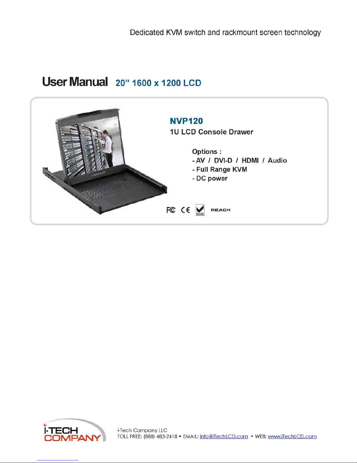
Dedicated KVM switch and rackmount screen technology
User Manual 20” 1600 x 1200 LCD
|-T~E^j|""I
i-Tech
Company LLC
C^DN^RA^TY
Page 2
Legal Information
First English printing, October 2002
Information in this document has been carefully checked for accuracy; however, no guarantee is given to the correctness
of the contents. The information in this document is subject to change without notice. We are not liable for any injury or
loss that results from the use of this equipment.
Safety Instructions
Please read all of these instructions carefully before you use the device. Save this manual for
future reference.
■ Unplug equipment before cleaning. Don't use liquid or spray detergent; use a moist cloth.
■ Keep equipment away from excessive humidity and heat. Preferably, keep it in an air-conditioned environment with
temperatures not exceeding 40° Celsius (104° Fahrenheit).
■ When installing, place the equipment on a sturdy, level surface to prevent it from accidentally falling and causing
damage to other equipment or injury to persons nearby.
■ When the equipment is in an open position, do not cover, block or in any way obstruct the gap between it and the
power supply. Proper air convection is necessary to keep it from overheating.
■ Arrange the equipment's power cord in such a way that others won't trip or fall over it.
■ If you are using a power cord that didn't ship with the equipment, ensure that it is rated for the voltage and current
labeled on the equipment's electrical ratings label. The voltage rating on the cord should be higher than the one listed
on the equipment's ratings label.
■ Observe all precautions and warnings attached to the equipment.
■ If you don't intend on using the equipment for a long time, disconnect it from the power outlet to prevent being
damaged by transient over-voltage.
■ Keep all liquids away from the equipment to minimize the risk of accidental spillage. Liquid spilled on to the power
supply or on other hardware may cause damage, fire or electrical shock.
■ Only qualified service personnel should open the chassis. Opening it yourself could damage the equipment and
invalidate its warranty.
■ If any part of the equipment becomes damaged or stops functioning, have it checked by qualified service personnel.
What the warranty does not cover
■ Any product, on which the serial number has been defaced, modified or removed.
■ Damage, deterioration or malfunction resulting from:
D Accident, misuse, neglect, fire, water, lightning, or other acts of nature, unauthorized product modification, or
failure to follow instructions supplied with the product.
□ Repair or attempted repair by anyone not authorized by us.
□ Any damage of the product due to shipment.
□ Removal or installation of the product.
□ Causes external to the product, such as electric power fluctuation or failure.
□ Use of supplies or parts not meeting our specifications.
□ Normal wear and tear.
□ Any other causes which does not relate to a product defect.
■ Removal, installation, and set-up service charges.
Regulatory Notices Federal Communications Commission (FCC)
This equipment has been tested and found to comply with the limits for a Class B digital device, pursuant to Part 15 of
the FCC rules. These limits are designed to provide reasonable protection against harmful interference in a residential
installation.
Any changes or modifications made to this equipment may void the user's authority to operate this equipment. This
equipment generates, uses, and can radiate radio frequency energy and, if not installed and used in accordance with the
instructions, may cause harmful interference to radio communications.
However, there is no guarantee that interference will not occur in a particular installation. If this equipment does cause
harmful interference to radio or television reception, which can be determined by turning the equipment off and on, the
user is encouraged to try to correct the interference by one or more of the following measures:
■ Re-position or relocate the receiving antenna.
■ Increase the separation between the equipment and receiver.
■ Connect the equipment into an outlet on a circuit different from that to which the receiver is connected.
Page 3
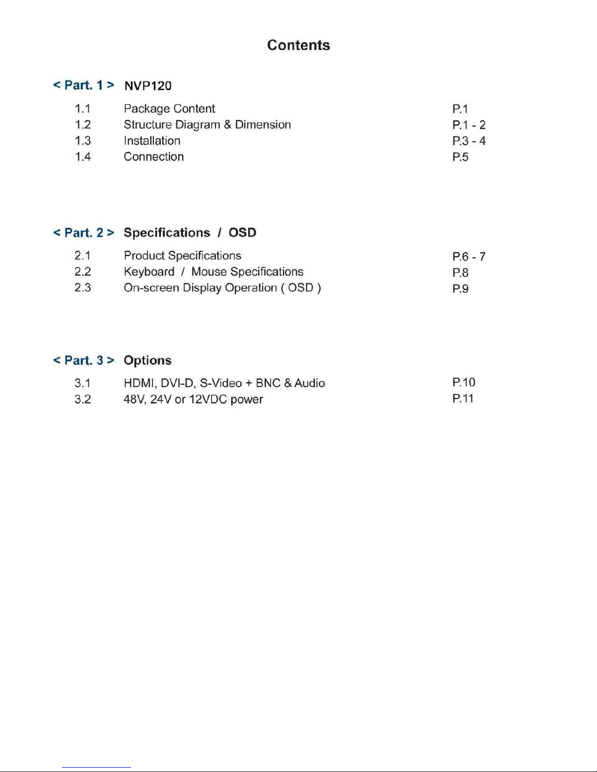
Contents
< Part. 1 >
NVP120
1.1
Package Content
1.2 Structure Diagram & Dimension
1.3
Installation
1.4 Connection
P.1
P.1
P.
3
P.5
< Part. 2 > Specifications / OSD
2.1 Product Specifications P.6
2.2 Keyboard / Mouse Specifications P.8
2.3 On-screen Display Operation (OSD) P.g
< Part. 3 > Options
3.1
HDMI,
DVI-D, S-Video +BNC & Audio P.1
3.2 48V, 24V or 12VDC power P.1
Page 4
Contents
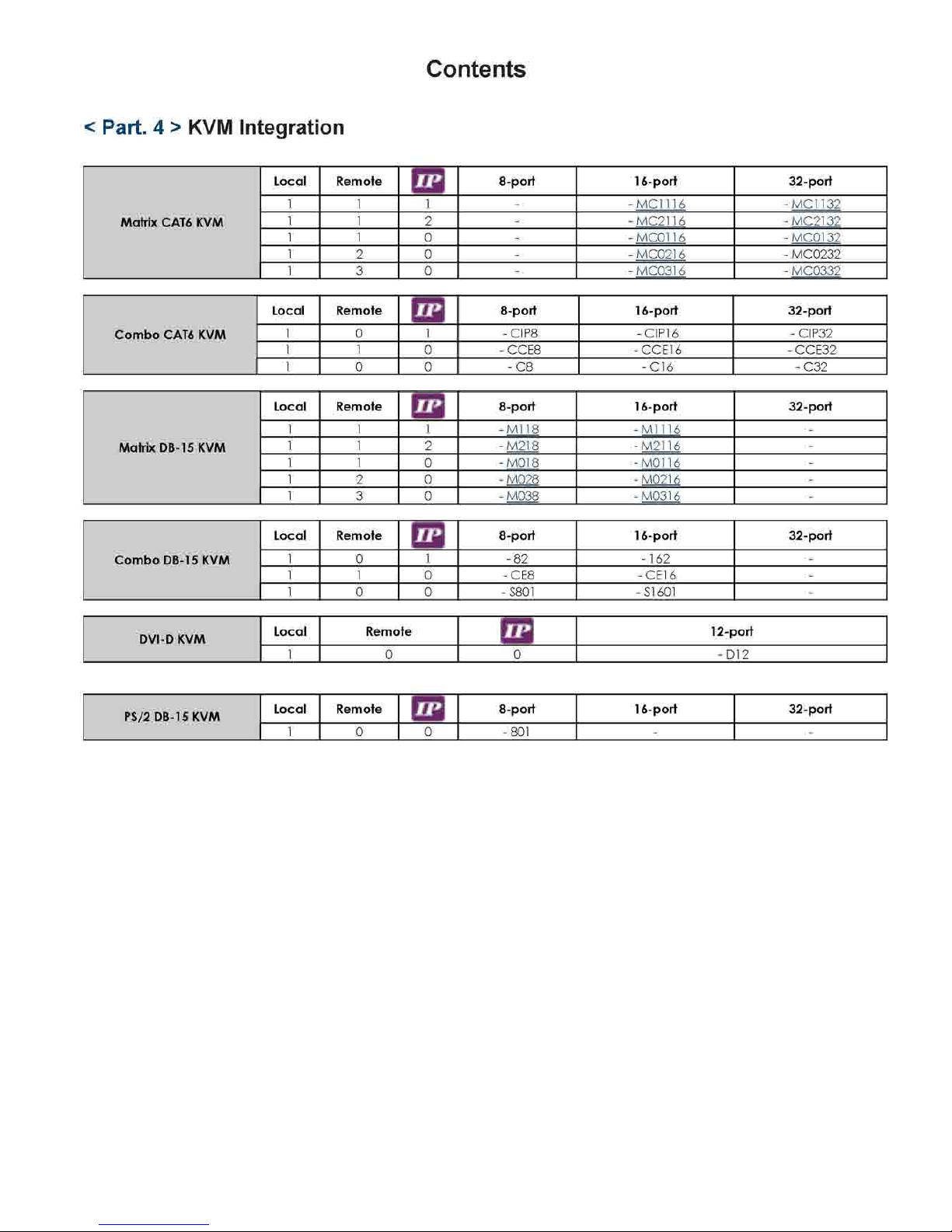
< Part. 4 > KVM Integration
Matrix CAT6 KVM
Local Remote
E3
8-port
16-port
32-port
Matrix CAT6 KVM
1 1 l - - MC1116 - MC1132
Matrix CAT6 KVM
1 1 2 - - MC2116 - MC2132
Matrix CAT6 KVM
1 1 0 - - MC0116 - MC0132
Matrix CAT6 KVM
1 2 0 - - MC0216 - MC0232
Matrix CAT6 KVM
1 3 0 - - MC0316 - MC0332
Combo CAT6 KVM
Local Remote
G3
8-port
16-port 32-port
Combo CAT6 KVM
1 0 l - CIP8 - CIP16 - CIP32
Combo CAT6 KVM
1 1 0 - CCE8 - CCE16 - CCE32
Combo CAT6 KVM
1 0 0 - C8 - C16 - C32
Matrix DB-15 KVM
Local Remote
Eza
8-port
16-port 32-port
Matrix DB-15 KVM
1 1 i - Ml 18 - Ml 116 -
Matrix DB-15 KVM
1 1 2 - M218 - M2116 -
Matrix DB-15 KVM
1 1 0 - M018 - MOl 16 -
Matrix DB-15 KVM
1 2 0 - M028 -
M021 6
-
Matrix DB-15 KVM
1 3 0 - M038 -
M031 6
-
Combo DB-15 KVM
Local Remote
EZ3
8-port
16-port 32-port
Combo DB-15 KVM
1 0 l - 82 - 162 -
Combo DB-15 KVM
1 1 0 - CE8 - CE16 -
Combo DB-15 KVM
1 0 0 - S801 -
SI
601 -
DVI-D KVM
Local Remote
(za
12-port
DVI-D KVM
1 0 0 - D12
PS/2 DB-15 KVM
Local Remote
cza
8-port
16-port 32-port
PS/2 DB-15 KVM
1 0 0 - 801 - -
Page 5
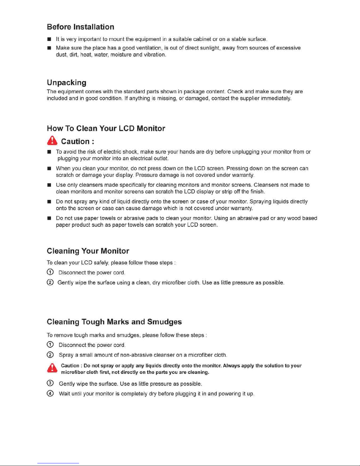
Before Installation
■ It is very important to mount the equipment in a suitable cabinet or on a stable surface.
■ Make sure the place has a good ventilation, is out of direct sunlight, away from sources of excessive
dust, dirt, heat, water, moisture and vibration.
Unpacking
The equipment comes with the standard parts shown in package content. Check and make sure they are
included and in good condition. If anything is missing, or damaged, contact the supplier immediately.
How To Clean Your LCD Monitor
4k Caution :
■ To avoid the risk of electric shock, make sure your hands are dry before unplugging your monitor from or
plugging your monitor into an electrical outlet.
■ When you clean your monitor, do not press down on the LCD screen. Pressing down on the screen can
scratch or damage your display. Pressure damage is not covered under warranty.
■ Use only cleansers made specifically for cleaning monitors and monitor screens. Cleansers not made to
clean monitors and monitor screens can scratch the LCD display or strip off the finish.
■ Do not spray any kind of liquid directly onto the screen or case of your monitor. Spraying liquids directly
onto the screen or case can cause damage which is not covered under warranty.
■ Do not use paper towels or abrasive pads to clean your monitor. Using an abrasive pad or any wood based
paper product such as paper towels can scratch your LCD screen.
Cleaning Your Monitor
To clean your LCD safely, please follow these steps :
® Disconnect the power
cord.
® Gently wipe the surface using a clean, dry microfiber cloth. Use as little pressure as possible.
Cleaning Tough Marks and Smudges
To remove tough marks and smudges, please follow these steps :
© Disconnect the power
cord.
© Spray a small amount of non-abrasive cleanser on a microfiber cloth.
^^ Caution : Do not spray or apply any liquids directly onto the monitor. Always apply the solution to your
•* microfiber cloth first, not directly on the parts you are cleaning.
® Gently wipe the surface. Use as little pressure as possible.
® Wait until your monitor is completely dry before plugging it in and powering it up.
Page 6
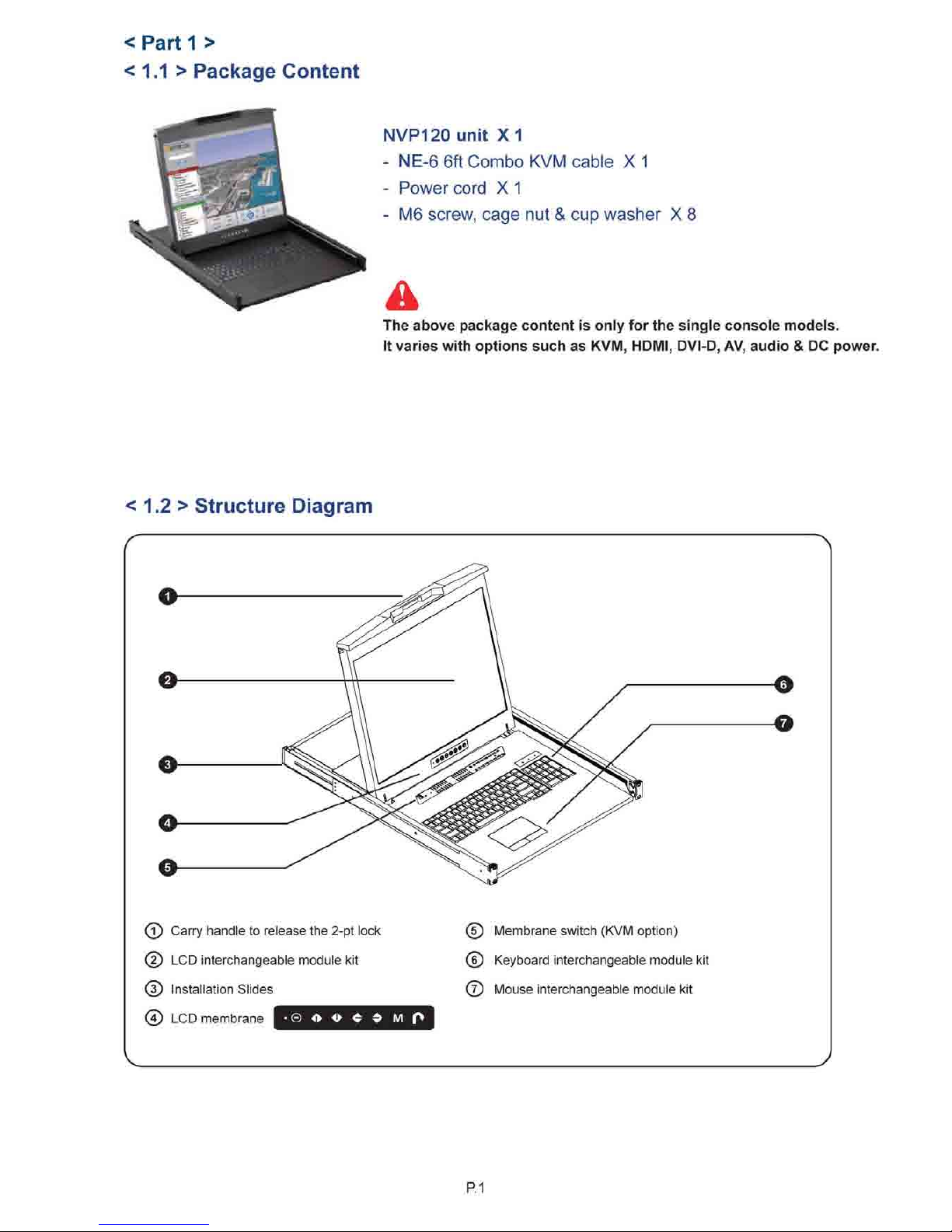
< Part 1 >
< 1.1 > Package Content
NVP120unit
X1
- NE-6
6ft
Combo KVM cable
X 1
- Power cord
X 1
- M6 screw, cage
nut &
cup washer
X 8
The above package content is only for the single console models.
It varies with options such as KVM,
HDMI,
DVI-D, AV, audio & DC power.
<
1.2 >
Structure Diagram
(T) Carry handle
to
release the
2-pt
lock
(5) LCD interchangeable module
kit
(D Installation Slides
(4) LCD membrane
© A <►
< ♦ M O
(5) Membrane switch (KVM option)
© Keyboard interchangeable module
kit
® Mouse interchangeable module
kit
P.1
Page 7
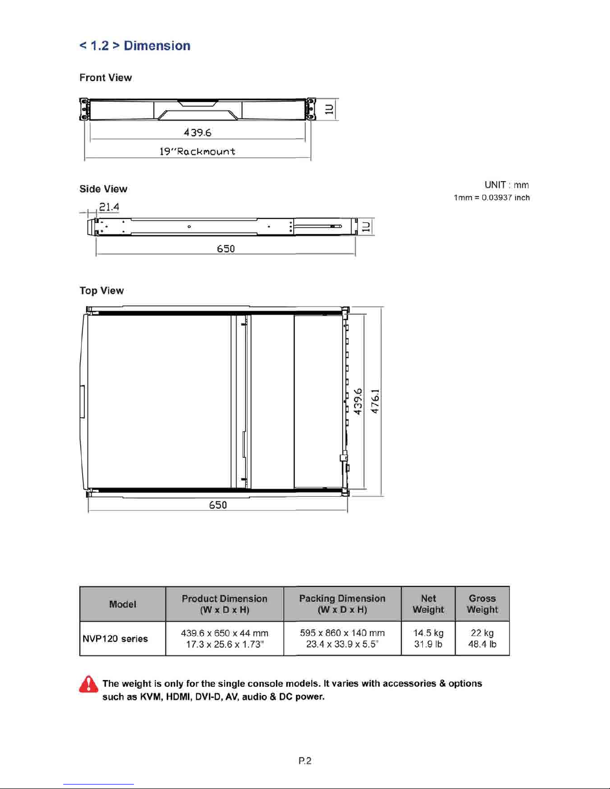
< 1.2 > Dimension
Front View
A
439.6
19"Racknount
Side View
21.4
_
[IF-^
650
UNIT: mm
1mm =
0.03937
inch
Top View
" "
£E
650
ff^
s
5=B
Model
Product Dimension
(W x D x H)
Packing Dimension
(W x D x H)
Net
Weight
Gross
Weight
NVP120 series
439.6x650x44 mm
17.3x25.6x1.73"
595 x 860 x 140 mm
23.4x33.9x5.5"
14.5 kg
31.9
1b
22 kg
48.4 lb
The weight is only for the single console models. It varies with accessories & options
such as KVM, HDMI, DVI-D, AV, audio & DC power.
P.2
Page 8
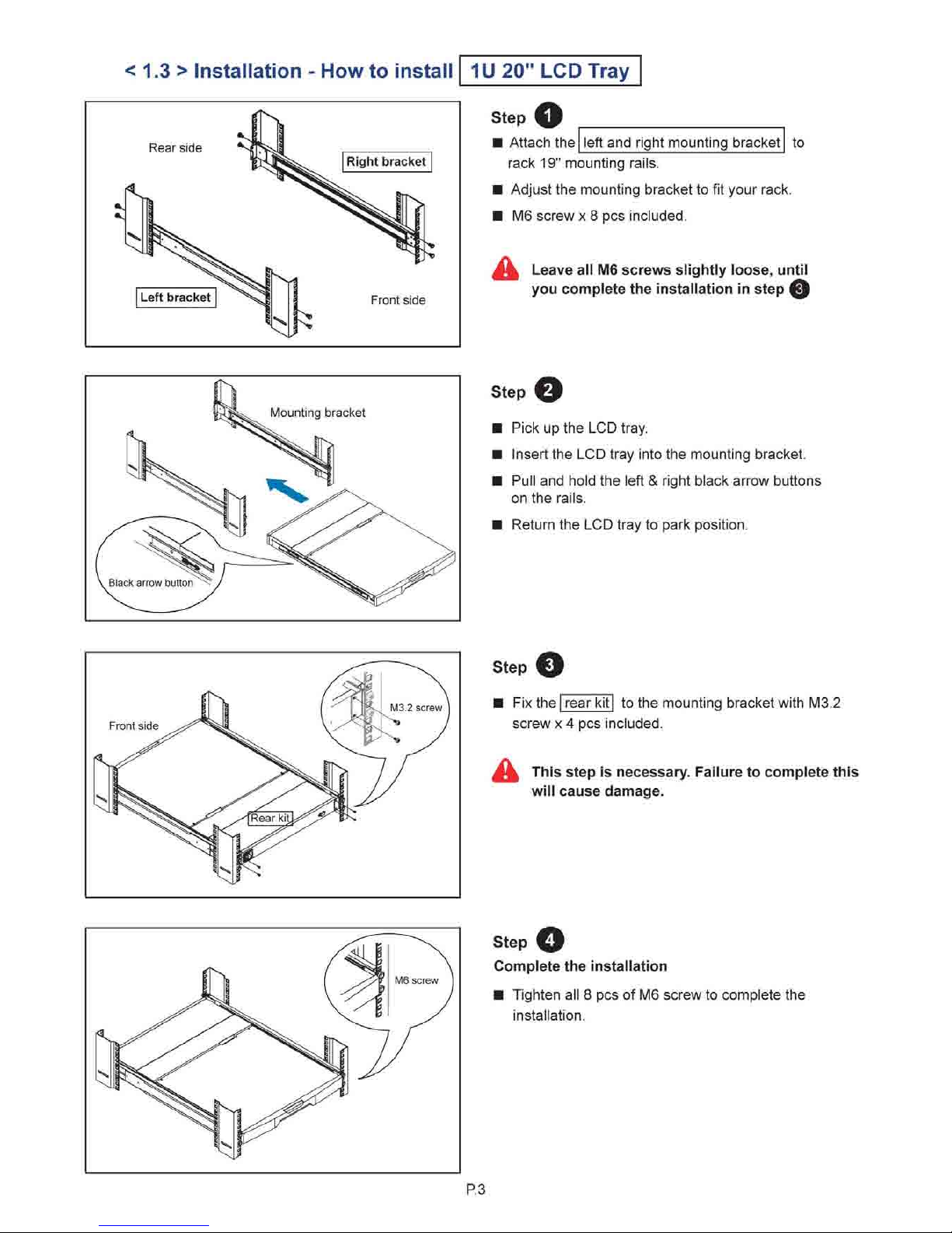
< 1.3 > Installation - How to install
Rear side
Left bracket
Right bracket
Front side
1U 20" LCD Tray
Step O
Attach the left and right mounting bracket
to
rack 19" mounting rails.
■ Adjust the mounting bracket to fit your rack.
■ M6 screw x 8 pcs included.
M± Leave all M6 screws slightly loose, until
you complete the installation in step Q
Mounting bracket
Step O
Pick up the LCD tray.
Insert the LCD tray into the mounting bracket.
Pull and hold the left & right black arrow buttons
on the rails.
Return the LCD tray to park position.
Front side
Step O
Fix the | rear kit| to the mounting bracket with M3.2
screw x 4 pcs included.
^ This step is necessary. Failure to complete this
will cause damage.
Step O
Complete the installation
Tighten all 8 pcs of M6 screw to complete the
installation.
P.3
Page 9
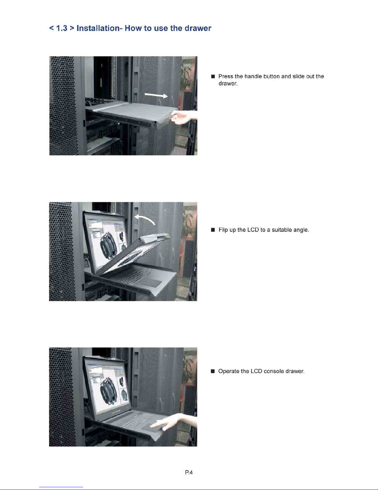
< 1.3 > Installation- How to use the drawer
■
W.7.V.V.7.
••••••»■•••
Press the handle button and slide out the
drawer.
If
.V.VAV.V.V
Flip up the LCD to a suitable angle.
Operate the LCD console drawer.
P. 4
Page 10
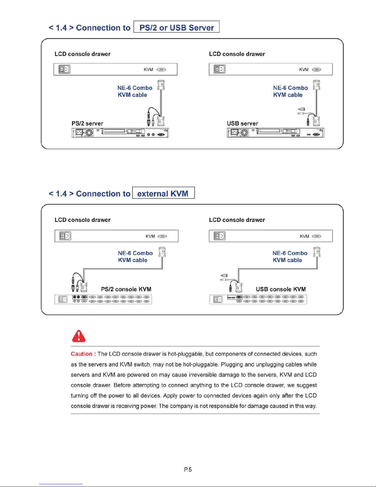
< 1.4 > Connection to PS/2 or USB Server
LCD console drawer
KVM «
LCD console drawer
m
KVM <m
NE-6 Combo
KVM cable
PS/2 server
U lHJ^gTTT;
wm @©
USB server
NE-6 Combo
KVM cable
isnoi w<^—w^urr
^S!
< 1.4 > Connection to external KVM
LCD console drawer
m
KVM *W>
90
£3 PS/2 console KVM
B
VV :'*: <M><Mfr«Q<$m&4M°<»fc«S»5>■^«fr
NE-6 Combo H
KVM cable
LCD console drawer
B
«B
KVM ^M>
NE-6 Combo F?
KVM cable
USB console KVM
Caution : The LCD console drawer is hot-pluggable, but components of connected devices, such
as the servers and KVM switch, may not be hot-pluggable. Plugging and unplugging cables while
servers and KVM are powered on may cause irreversible damage to the servers, KVM and LCD
console drawer. Before attempting to connect anything to the LCD console drawer, we suggest
turning off the power to all devices. Apply power to connected devices again only after the LCD
console drawer is receiving power. The company is not responsible for damage caused in this way.
P. 5
Page 11
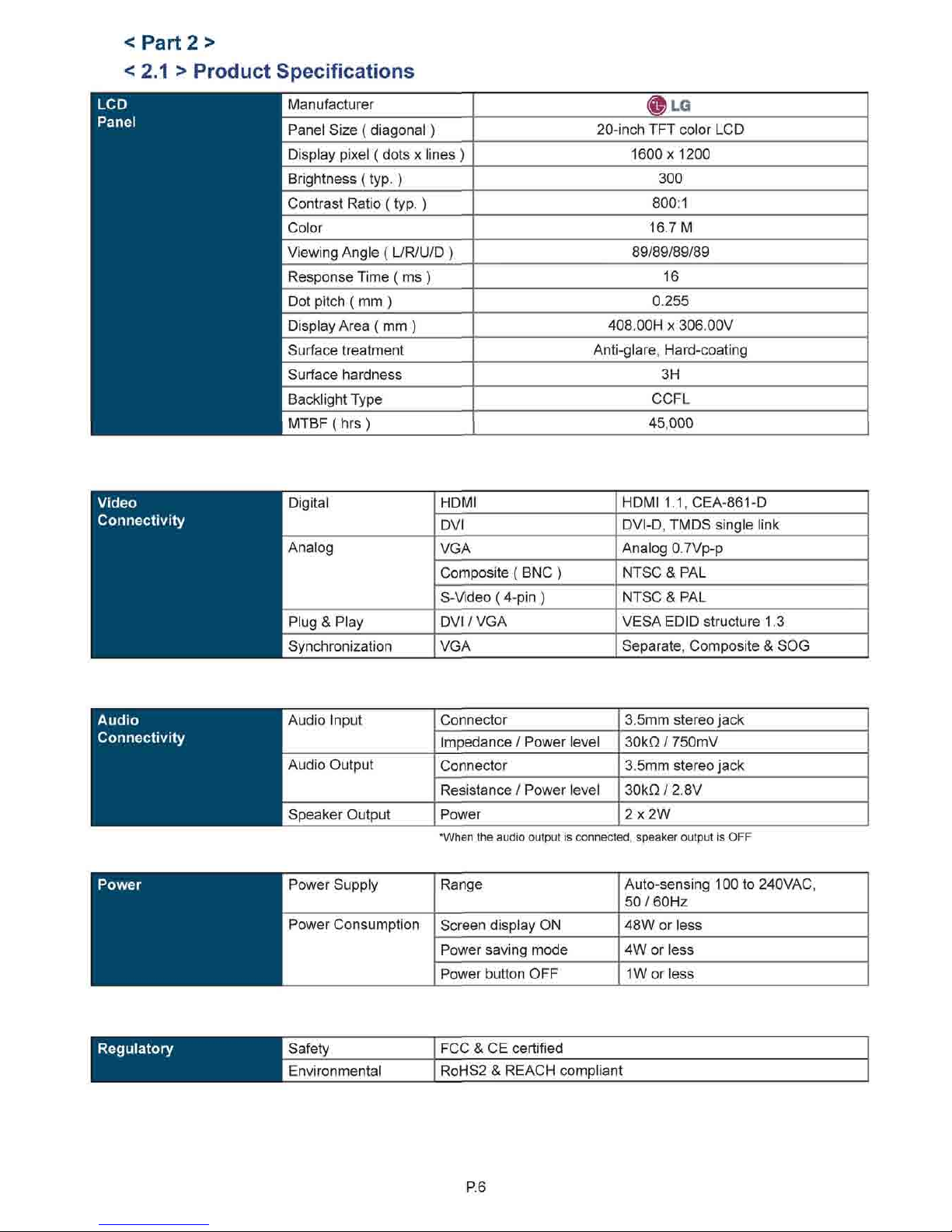
< Part 2 >
< 2.1 > Product Specifications
Manufacturer
®LG
Panel Size ( diagonal)
20-inch TFT color LCD
Display pixel ( dots x lines )
1600x1200
Brightness (typ. )
300
Contrast Ratio (typ. )
800:1
Color
16.7 M
Viewing Angle (
L/R/U/D
)
89/89/89/89
Response Time ( ms )
16
Dot pitch ( mm )
0.255
Display Area ( mm )
408.00H x 306.00V
Surface treatment
Anti-glare, Hard-coating
Surface hardness
3H
Backlight Type
CCFL
MTBF ( hrs )
45,000
Video
Connectivity
Digital
HDMI
HDMI
1.1.CEA-861-D
Digital
DVI
DVI-D,
TMDS single link
Analog
VGA
Analog
0.7Vp-p
Analog
Composite (BNC ) NTSC & PAL
Analog
S-Video(
4-pin
)
NTSC & PAL
Plug & Play
DVI / VGA VESA EDID structure 1.3
Synchronization VGA
Separate, Composite & SOG
Audio
Connectivity
Audio Input
Connector
3.5mm
stereo jack
Audio Input
Impedance / Power level 30kQ / 750mV
Audio Output
Connector
3.5mm
stereo jack
Audio Output
Resistance / Power level 30kO / 2.8V
Speaker Output
Power 2x2W
*When the audio output is connected, speaker output is OFF
Power Supply
Range Auto-sensing 100 to 240VAC,
50/60HZ
Power Consumption
Screen display ON 48W or less
Power Consumption
Power saving mode
4W or less
Power Consumption
Power button OFF 1W or less
Regulatory
I Safety
FCC & CE certified
| Environmental
RoHS2 & REACH compliant
R6
Page 12
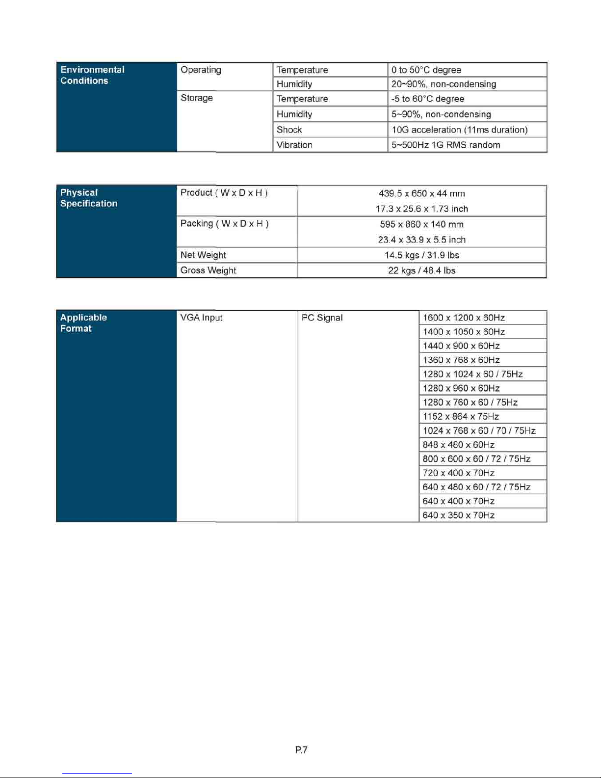
Environmental
Conditions
Operating
Temperature 0 to 50°C degree
Operating
Humidity
20-90%,
non-condensing
Storage
Temperature -5 to 60°C degree
Storage
Humidity 5-90%, non-condensing
Storage
Shock 10G acceleration
(11
ms duration)
Storage
Vibration
5~500Hz
1G RMS random
Physical
Specification
Product ( W x D x H )
439.5x650x44 mm
17.3x25.6x1.73 inch
Physical
Specification
Packing (WxDxH )
595 x 860 x 140 mm
23.4x33.9x5.5 inch
Packing (WxDxH )
595 x 860 x 140 mm
23.4x33.9x5.5 inch
Net Weight 14.5 kgs/31.9 lbs
Gross Weight 22 kgs/48.4 lbs
VGA Input PC Signal 1600 x1200 x60Hz
1400 x1050 x60Hz
1440 x900 x60Hz
1360 x768 x60Hz
1280 x 1024 x 60 / 75Hz
1280 x960 x60Hz
1280x760x60/75Hz
1152 x864 x75Hz
1024x768x60/70/75Hz
848 x 480 x 60Hz
800 x 600 x 60 / 72 / 75Hz
720 x400 x70Hz
640 x 480 x 60 / 72 / 75Hz
640 x 400 x 70Hz
640 x 350 x 70Hz
P. 7
Page 13
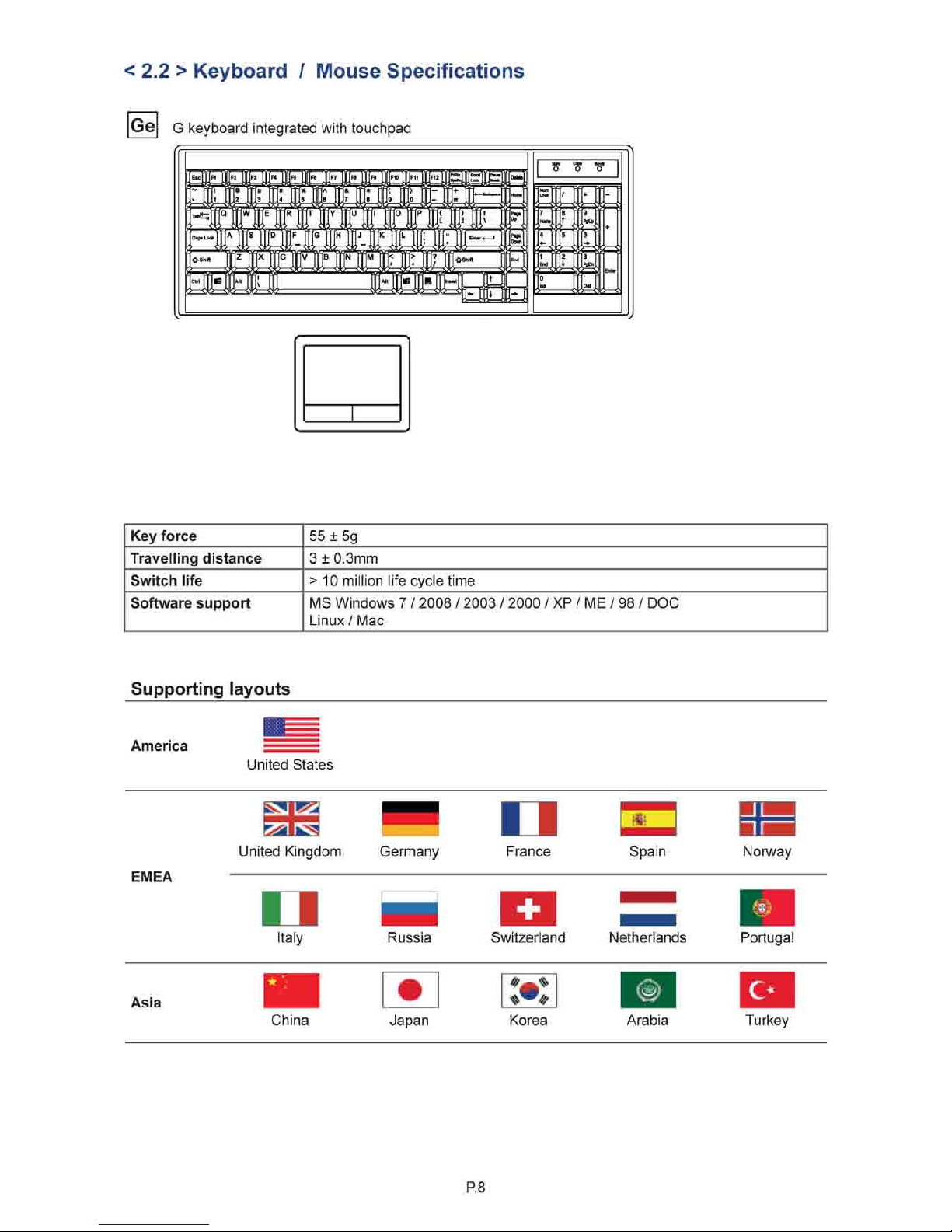
< 2.2 > Keyboard / Mouse Specifications
Ge G
keyboard integrated with touchpad
pEEEEIg
*•
tji tie ¥ #r :*r:% | TA : ■&
T*7ff<y
'
■'! — 1
^^^^^ffl^^n
MttMJJK
■
■
Key force 55 ± 5g
Travelling distance 3 ± 0.3mm
Switch life > 10 million life cycle time
Software support MS Windows
7 /
2008 / 2003 / 2000 / XP / ME / 98 / DOC
Linux/ Mac
Supporting layouts
America
United States
EMEA
United Kingdom
n
Italy
Germany
n
France Spain Norway
Russia Switzerland Netherlands Portugal
Asia
China Japan Korea Arabia Turkey
P. 8
Page 14
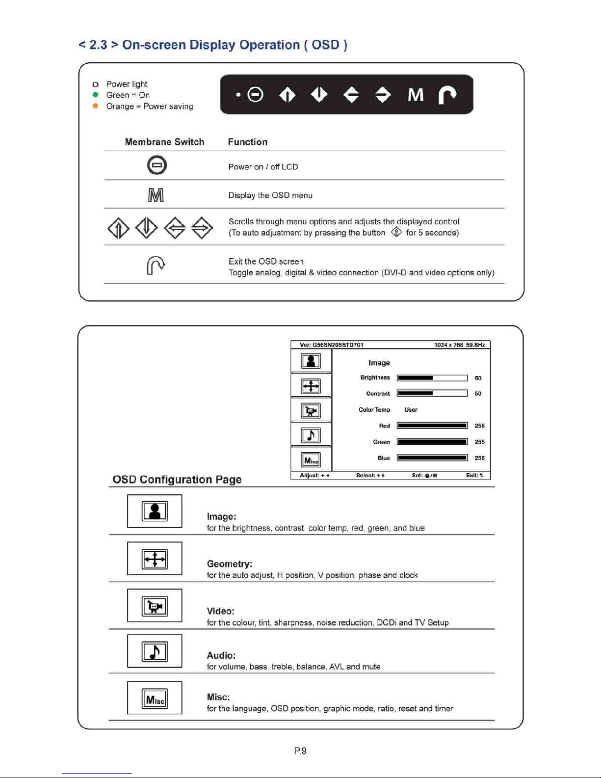
< 2.3 > On-screen Display Operation ( OSD
)
O Power light
• Green
= On
Orange = Power saving
© <►
i> < ♦ M f>
Membrane Switch Function
e
Power on
/ off
LCD
M
Display the OSD menu
4>4»<£#
Scrolls through menu options and adjusts the displayed control
(To auto adjustment by pressing the button
4K
f°r 5 seconds)
(p>
Exit the OSD screen
Toggle analog, digital & video connection (DVI-D and video options only)
^
OSD Configuration Page
Ver: G56SN20SSTD701
1024x768 59.8Hz
Mi
Image
Brightness
[1
]
50
Contrast
|
]
50
Color Temp User
Red
1^^^
[
255
Green
[|
0
255
Blue
]
[
255
Adjust:
Select:**
Set:
®/l=J
Exit: t
IAJ
Image:
for the brightness, contrast, color
temp,
red, green, and blue for the brightness, contrast, color
temp,
red, green, and blue
rrl
Geometry:
for the auto adjust, H position, V position, phase and clock for the auto adjust, H position, V position, phase and clock
*
Video:
for the colour, tint, sharpness, noise reduction, DCDi and TV Setup for the colour, tint, sharpness, noise reduction, DCDi and TV Setup
•h
Audio:
for volume, bass, treble, balance, AVL and mute for volume, bass, treble, balance, AVL and mute
Misc
Misc:
for the language, OSD position, graphic mode, ratio, reset and timer
Misc:
for the language, OSD position, graphic mode, ratio, reset and timer
P. 9
Page 15
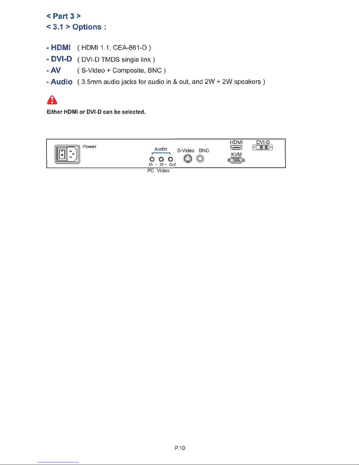
< Part 3 >
< 3.1 > Options :
- HDMI ( HDMI 1.1, CEA-861-D )
- DVI-D ( DVI-D TMDS single link )
- AV ( S-Video + Composite, BNC )
- Audio ( 3.5mm audio jacks for audio in & out, and 2W + 2W speakers )
Either HDMI or DVI-D can be selected.
H
Power
Audio
i 1
© o o
in - in - out
S-Video BNC
HDMI DVI-D
[o|
III'
PC Video
P.10
Page 16
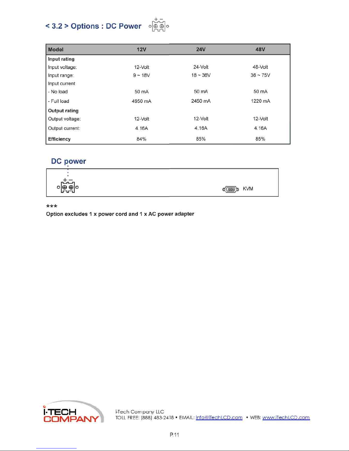
<
3.2 >
Options
: DC
Power
Model
12V
24V 48V
Input rating
Input voltage: 12-Volt
24-Volt 48-Volt
Input range: 9-18V
18-36V 36 ~ 75V
Input current
-
No
load 50 mA
50 mA 50 mA
- Full load 4950
mA
2450
mA
1220 mA
Output rating
Output voltage: 12-Volt
12-Volt 12-Volt
Output current:
4.16A
4.16A 4.16A
Efficiency
84%
85% 85%
DC power
***
Option excludes 1 x power cord and 1 x AC power adapter
l-TECH
COMPANV
i-Tech
Company
LLC
TOLL FREE:
(888)
P.11
 Loading...