

Page 1

Page 2

Page 2
Content
Introduction........................................................................................................... 3
Hardware Installation............................................................................................ 3
The Display Timing...............................................................................................5
The Display Outline Dimensions.......................................................................... 6
The Display Controls............................................................................................ 7
The Screen Adjustment........................................................................................ 8
Troubleshooting Tips..........................................................................................10
Specification........................................................................................................11
Product Safety Precautions................................................................................ 12
Page 3

Page 3
Introduction
Welcome to enjoy the fantastic sightseeing world. This new technology will bring you the whole
new feeling about the “monitor”. We show here some of the major advantages of the LCD
monitor. You will really find some other advantages when you use it.
Hardware Installation
This chapter will guide you the correct installation procedures of your LCD monitor.
Unpacking
After you unpack your LCD Monitor, please make sure that the following items are included in the
carton and in good condition. If you find that any of these items are damaged or missing, please
contact your dealer immediately.
One LCD Monitor
15-pin D-sub Video cable (Option)
AC/DC adapter with 12V DC output (Option)
AC power cord (Option)
Quick installation Guide
Installation
This analog LCD display does not require any special drivers. Necessary drivers are supplied
by the video card manufacturer and may be found on the diskettes supplied with the video card
that came with your computer. Windows 98/2000/XP drivers for both the display and the video
card are supplied on the Windows 98/2000/XP CD or diskettes. Unfortunately, Microsoft did not
provide a complete listing of the displays on the initial retail release. You may use the standard
XGA (1024x768) as the display type. The video card must also be set up correctly in Windows
98/2000/XP and make sure the video output of the VGA card is on list in Section 6.1 or check your
Video Card manual or Windows 98/2000/XP Read me file for further information on Video Card.
After the question listed above is solved, we continue the setup procedure as below.
1. Turn power off both Computer and Display before making any connection.
2. Install Display on the solid horizontal surface such as a table or desk.
3. Connect the power cable and the AC/DC adapter, then connect adapter toe the back of the
LCD monitor.
4. The LCD monitor comes with a 15-pin video cable; you may use this cable for both IBM PC’s
& compatibles and Macintosh.
5. Tighten the screws of the Display cable until the connectors are fastened securely.
6. Switch on power to the Computer system, then to the monitor.
Page 4
Page 4
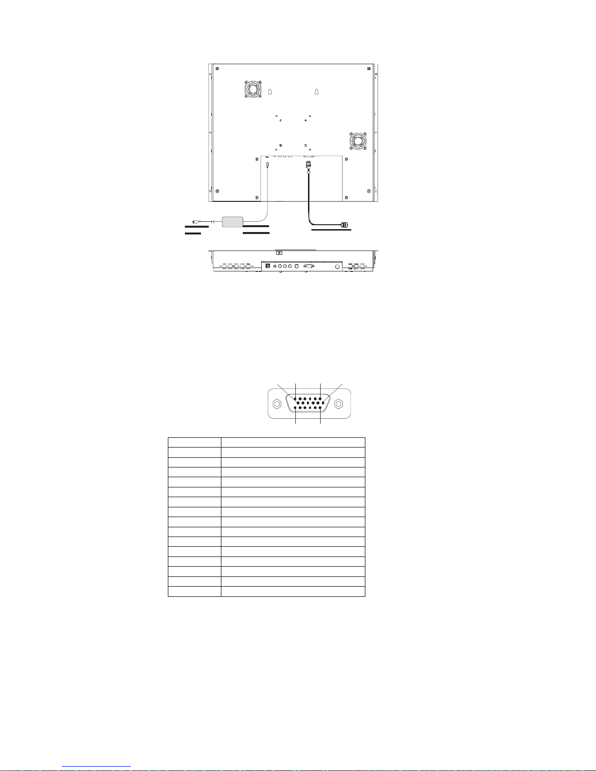
The following picture provides the connection outline
Video Input Pin Assignment
This section describes the pin assignment of the LCD’s video connector. It is called 15pin Mini
D-sub connector.
110 6
11515
Pin No. Signal Connector
1 Red Video Signal
2 Green Video Signal
3 Blue Video Signal
4 N.C.
5 Ground
6 Ground for red video signal
7 Ground for green video signal
8 Ground for blue video signal
9 N.C.
10 Ground
11 N.C.
12 DDC data
13 Horizontal sync signal
14 Vertical sync signal
15 DDC clock
Page 5

Page 5
The Display Timing
Applicable video timing
The following table lists the better display quality modes that the LCD monitor provides. If the
other video modes are input, the monitor will stop working or display unsatisfactory picture quality.
VESA Modes
Mode Resolution Total Nominal
Frequency
±0.5KHz
Nominal
Frequency
±0.5KHz
Nominal
Pixel Clock
(MHz)
DOS 720x400@70Hz 900x449 31.469 70.087 28.322
640x480@60Hz 800x525 31.469 59.940 25.175
640x480@72Hz 832x520 37.861 72.809 31.500
VGA
640x480@75Hz 840x500 37.500 75.000 31.500
800x600@56Hz 1024x625 35.156 56.250 36.000
800x600@60Hz 1056x628 37.879 60.017 40.000
800x600@72Hz 1040x666 48.077 72.188 50.000
SVGA
800x600@75Hz 1056x625 46.875 75.000 49.500
1024x768@60Hz 1344x804 48.363 60.004 65.000
1024x768@70Hz 1328x806 56.476 70.069 75.000
XGA
1024x768@75Hz 1312x800 60.023 75.029 78.750
IBM Modes
EGA 640x350@70Hz 800x449 31.469 70.086 25.175
DOS 720x400@70Hz 900x449 31.469 70.087 28.322
VGA 640x480@60Hz 800x525 31.469 75.000 31.500
XGA 1024x768@72Hz 1304x798 57.515 72.100 75.000
MAC Modes
VGA 640x480@60Hz 800x525 31.469 59.940 25.175
SVGA 832x624@75Hz 1152x667 49.725 74.551 57.2832
XGA 1024x768@75Hz 1328x804 60.927 74.927 80.000
Page 6

Page 6
The Display Outline Dimensions
Unit: mm
Page 7

Page 8

Page 8
The Screen Adjustment
Main Menu
You can adjust the brightness, contrast, display colors, the horizontal and vertical position of the
display and OSD menu, etc. through the main menu display.
The Down Key < and Up Key >are used to scroll through items within the menu. The selected
item is highlighted as the scrolling move along. The SELECT key is used to activate the
highlighted item. During this state, MENU key is used to close the OSD menu from the screen.
Page 9

OSD Control Key
Power key : Power ON/OFF.
Menu key : Enter the main menu of the on-screen display (OSD).
Down key : Decrease item number or item value when OSD is on.
Decrease volume gain when OSD is off.
Up key : Increase item number or value of the selected item when .
Increase volume gain when OSD is off.
Select key : Activate the selected icon or function.
Source key : Input source select (PC, AV, S-Video ,TV, Component).
Channel up key : Increase TV channel number.
Channel down key : Decrease TV channel number.
Page 9
The Screen Adjustment
Page 10

OSD Control Function List
◆ OSD For PC input
Page 10
The Screen Adjustment
Page 11

Main Menu:
Press “Up” or “Down” to locate the item you desire to change, then press “Select”
to make the adjustment, press “Menu” again to go back to previous menu.
Picture Adjust
This item can adjust Auto Adjust, Brightness, Contrast, Pixel
Clock, Phase, H-Position and V-Position for an optimal image.
Color
This item can select 9300/6500 color temperature or adjust
USER color.
Audio
This item can adjust audio function, as Volume, Mute, Treble,
Base, Balance.
PIP
This item can control Picture in Picture (PIP) function.As
picture sub source, audio source, sub source SIZE, H-Position,
V-Position, and change sub picture color setting.
SYSTEM
This item can Select Source input (PC, AV, S-Video, TV,
Component.) and Recall System data.
OSD
This item can control OSD window function.As OSD H-Position,
OSD V-Position, OSD Transparence and OSD Off time.
Picture Adjust
Auto Adjust
Automatically adjusts H-Position, V-Position, Pixel
Clock and Phase for an optimal image.
Press “Select” to execute.
Brightness
Adjusts the Brightness.
Press “Up” or “Down“ to adjust the parameter.
Contrast
Adjusts the difference between the light and dark areas.
Press “Up” or “Down“ to adjust the parameter.
Clock
Adjusts the video distortion. It will appear horizontal
noise on the screen while adjust the Clock.
Press “Up” or “Down“ to adjust the parameter.
Phase
Adjusts the video distortion. It will appear vertical noise
on the screen while adjust the Phase.
Press “Up” or “Down“ to adjust the parameter.
Page 11
The Screen Adjustment
Page 12

Horizontal Position
Moves the display picture.
Press “Up” to the right or press “Down“ to the left.
Vertical Position
Moves the display picture.
Press “Up” to the up or press “Down“ to the down.
Color
9300K
Select 9300 color temperature
Press “Select” to execute.
6500K
Select 6500 color temperature
Press “Select” to execute.
User
Select USER color temperature
Press “Select” to execute.
Red
Adjust gain of the Red color
Press “Up” or “Down“ to adjust the parameter.
Green
Adjust gain of the Green color
Press “Up” or “Down“ to adjust the parameter.
Blue
Adjust gain of the Blue color
Press “Up” or “Down“ to adjust the parameter.
Page 12
The Screen Adjustment
Page 13

Audio
Volume
Adjust Volume gain
Press “Up” to increase or press “Down“ to decrease.
Mute
Set Audio mute.
Press “Up” to execute mute or Press “Down“ to release
mute.
Treble
Adjust audio Treble .
Press “Up” to increase or press “Down“ to decrease.
Bass
Adjust audio bass .
Press “Up” to increase or press “Down“ to decrease.
Balance
Input source select.
Press “Up” to right or press “Down“ to left.
Page 13
The Screen Adjustment
Page 14

PIP
Sub Source
This item can select sub source (Off, AV, S-Video, TV, and
Component)
Press “Select” to execute..
Audio
Select audio come from Main Source or Sub Source.
Press “Up” to come form Main Source
Press “Down” to come form Sub Source.
Size
Change the Sub Picture Size.
It supports 4 step size( 0% ,33% ,66%, 100%)
Press “Up “ to enlarge the sub picture
Press “Down” to reduce the sub picture.
H-Position
Moves the Sub Picture.
Press “Up” to the right or press “Down“ to the left.
V-Position
Moves the Sub Picture.
Page 14
The Screen Adjustment
Page 15

Press “Up” to the up or press “Down“ to the down.
PIP Color
Change the Sub Picture color setting.
Press “Select” to execute.
Five items can be adjusted in PIP color function
Brightness: Adjusts the sub picture brightness.
Contrast: Adjusts the sub picture contrast.
Saturation: Between colorful and colorless.
Hue: Color varying
Sharpness: Adjusts the Sharpness.
Press “Up” to increase or press “Down“ to decrease.
System
Recall
Restore the default value.(The value according to the
factory mode)
Press “Select” to execute.
Source
Input source select. (PC, AV, S-Video, TV, Component)
Press “Select” to execute..
OSD
OSD H-Position
Adjusts the OSD position left or right
Press “Up” to right, press “Down“ to left.
Page 15
The Screen Adjustment
Page 16

OSD V - Position
Adjusts the OSD position up or down
Press “Up” to up, press “Down“ to down.
OSD Transparence
Adjusts the OSD transparency.
Press “Up” or “Down“ to adjust the parameter.
Off Time
Adjusts the OSD exit time.
Press “Up” or “Down“ to adjust the parameter.
◆ OSD For Video input
Press “Up” or “Down” to locate the item you desire to change, then press “Select” to
make the adjustment, press “Menu” again to go back to previous menu.
Page 16
The Screen Adjustment
Page 17

Image Adjust
This item can adjust video color as Brightness, Contrast,
Saturation Hue, Sharpness.
Audio
This item can adjust audio function. As Volume, Mute, Treble,
Base, Balance.
System
This item can Select Source input (PC, AV, S-Video, TV,
Component.) and Recall System data.
OSD
This item can control OSD window function. As OSD
H-Position, OSD V-Position, OSD Transparence and OSD Off
time.
All functions adjustment are same as PC mode
◆ OSD for TV input
Press “Up” or “Down” to locate the item you desire to change, then press “Select”
to make the adjustment, press “Menu” again to go back to previous menu.
Page 17
The Screen Adjustment
Page 18

Page 18
The Screen Adjustment
Page 19

Image Adjust, Audio, System and OSD are same as Video mode
AIR / CATV
Select Air TV or Cable TV system
Press “Up” for Cable TV or press “Down” for Antenna TV
MTS
Set Multi-Channel Television Sound.
STEREO: A primary language and Hi-Fi system broadcast.
SAP: A second language broadcast.
MONO: A primary language and Mono system broadcast.
Press “Up” or “Down” to select then press “Select”
Page 19
The Screen Adjustment
Page 20

Channel
Change the TV Channel .
Press “Up” to next channel or press “Down“ to previous
channel.
CH Memory
Channel memories or erase .
Press “Up” to add a new channel or press “Down“ to erase
a channel.
CH Search
Auto Channel scan .
Press “Select” to execute.
Sleep
Setup the TV Sleep timer for Disable/10/20/30/40/50/60/90
minutes.
Press “Up” to increase sleep timer or press “Down“ to
decrease sleep timer.
Page 20
The Screen Adjustment
Page 21

. Remote Control Function List
1. POWER
Power On/Off.
2. Input Source Select
TV: Select TV video input.
PC: Select PC-VGA input.
AV: Select AV video input.
S-VIDEO: Select S-VIDEO video input.
COMP.: Select Component video input
14 3. MEMORY
Channel memories or erase.
13 4. OSD Control
MENU: Turns On/Off the On-Screen Display.
12 1 SELECT: Execute your selection.
“-“: Select the Item or decrease the value.
“+”: Select the Item or increase the value.
5. MUTE
Sound On or Off.
6. DISPLAY
11 2 Shown a channel number in the screen.
7. CHANNEL
3 Change the channel.
15 8. VOLUME
17 Adjust the volume.
16 9. JUMP
4 Return to last the TV channel.
10. MTS
Multi-Channel Television sound select.
10 5 Stereo→SAP→Mono
11. Digital key from 0 to 9 and above 100.
9 6 Use to select a TV channel.
12. SCAN
Auto scan TV program.
13. AIR/CA TV
Select the input source from Cable TV or
8 7 Antenna TV.
14. SLEEP
Setup the sleep timer.
15. PIP
Enable the PIP function
16. Source
Select the Sub. source of Video
17. Audio
Select the PC/Video audio source
Page 21
The Screen Adjustment
Page 22

Page 22
Quick Installation
Step 1
Step 2
Step 3
Step 4
Step 5
Step 6
Step 7
Plug one terminal of the VGA cable to the signal connector at the rear of the LCD Monitor.
Plug the other terminal of the VGA cable to the signal connector at the rear of PC.
Plug Adapter output to the jack at the rear of LCD Monitor.
Plug the Power cord to the Adapter.
Connect the Power cord to power outlet.
Turn on the LCD Monitor and PC.
You can also plug in RCA jack to connect your video source like DVD or VCR.
You can view video over PC by pressing "PIP" button on remote controller.
Please followthefollowingdescriptionsstepbystep.
(The7diagrams canalsobeyourreferences):
Step 1 Step 2 Step 3 Step 4 Step 5 Step 6 Step 7
Page 23

Page 23
Troubleshooting Tips
In the event that you experience trouble with your Display, check the following items before
contacting the dealer from whom the Display was purchased. The most common problems
usually involve an incorrectly an incorrect connection from the Video Card to the Display. We
recommend that you also consult your Video Card User’s manual during the Troubleshooting
Procedure. Do not exceed the maximum refresh rate recommended for the display.
Problem Troubleshooting Tip
No image on display
screen
1. Check that power cord of the Computer has been
connected securely into wall outlet or grounded
extension cable or strip.
2. Check that power switch of the Display has been
pressed and LED on the front of Display is lit.
3. Check that Video (Signal) cable from the Display
has been securely and correctly connected.
4. Check that Video Card is firmly seated in card slot
of Computer motherboard.
5. Check that the video input from the Video Card
falls within the timing range.
Abnormal image 1. Check that the video input from the Video Card
falls within the timing range.
2. Check that Video (Signal) Cable from the Display
has been securely and correctly connected to the
Video Connector at the rear side of the Computer.
Colors of image on
screen are abnormal
1. Check that Video (Signal) Cable from the displays
has been securely and correctly connected to the
15-pin Video Connector at the rear side of the
computer.
Disturbances on
Screen
1. OSD adjustment is incorrect. Please consult
section for OSD screen adjustment procedures.
※Please contact your local authorized distributors /retailers if you run into other unsolved problems.
Page 24

Page 25

Page 25
Product Safety Precautions
Follow all warnings and instructions marked on the product.
Do not use this product near water.
This display should be installed on a solid horizontal base.
When cleaning, use only a neutral detergent cleaner with a soft damp cloth.
Do not spray with liquid or aerosol cleaners.
Do not expose this display to direct sunlight or heat. Hot air may cause damage to the cabinet
and other parts.
Adequate ventilation must be maintained to ensure reliable and continued operation and to
protect the display from overheating. Do not block ventilation slots and openings with objects or
install the display in a place where ventilation may be hindered.
This display should be operated from the type of power source indicated on the AC/DC adapter.
Do not install this display near a motor or transformer where strong magnetism is generated.
Images on the display will become distorted and the color irregular.
Do not allow metal pieces or objects of any kind fall into the display from ventilation holes.
Do not attempt to service this unit yourself. Removal of the display cover may expose you to
dangerous voltage or other risks. Refer all servicing to qualified service personnel.
Unplug this product from the wall outlet and refer servicing to qualified service personnel in the
event that:
1. Liquid is spilled into the product or the product is exposed to rain or water.
2. The product does not operate normally when the operating instructions are followed.
3. The product has been dropped or the cabinet has been damaged.
4. The product exhibits a distinct change in performance, indicating a need for service.
5. Power cord or plug is damaged or frayed.
General specifications for the LCD
The following items are neither defects nor failures.
Response time, luminance and color gamut may be changed by
ambient temperature.
The LCD may be seemed luminance uniformity, flicker, vertical seam
and/or small spot by display patterns.
Optical characteristics ( e.g. luminance, display uniformity, etc. )
gradually is going to change depending on operating time, and
especially low temperature, because the LCD has cold cathode
fluorescent lamps.
 Loading...