

Page 1

U
p
d
r
m
8
8
M
l
8
o
t
8
O
0
h
M
e
0
Via Acquanera, 29 22100 Como
tel. 031.526.566 (r.a.) fax 031.507.984
info@calpower.it www.calpower.it
IT88
0 User
Manual
DC
Mo
se
rogra
el
IT8
IT8
’s
mab
17/IT88
18/IT8
an
e elec
17B/IT8
18B/IT8
ual
ronic
17C
818C
load
© C
pyright 20
Ver1.2 /
1
10 All Rig
ct, 2013/
t Reserv
IT8800-7
User
d
1
anual
Page 2

E
S
E
C
S
E
O
2
3
R
A
F
O
E
A
U
E
C
P
2
3
4
P
2
Y
O
R
T
T
A/B
2
3
S
A
V
O
E
g
N
C
E
t
s
e
L
N
I
E
N
H
C
A
C
T
M
p
U
U
C
U
O
N
o
o
O
C
A
o
a
T
O
N
P
A
D
O
m
c
o
t
M
)
O
(
g
T
E
A
C
T
C
)
)
C
)
o
C
IT88
0
0 User
Manual
CHAPT
1.1 I
1.2
CL
1.3 A
1.4 I
1.4.
1.4.2 I
CHAPT
2.1 P
2.1.
2.1.
2.1.
2.2 F
2.3R
2.4 V
2.5 K
2.6 C
CHAPT
R1 INSP
N
PECTION
ANING
CESSORY
N
TALLATION
1 Mountin
NPUT CON
R 2 QUI
WER-ON S
1 Introduc
Selftest
If the el
ONT PANE
E
R PANEL I
D
STATUS
E
Y BOARD D
MBINATIO
R3 TEC
CTION
..
................
.....
................
.
................
SITE
Dimensi
ECTIONS
K START
LFTEST
ion ..........
teps .......
ctronic lo
INTRODUC
TRODUCTI
NDICATOR
SCRIPTIO
KEYS
NICAL S
.........
..
....
.......
DIR
ND INST
................
................
................
................
ns ...........
................
................
................
................
................
d can’t po
ION
.........
N
............
LAMP DES
...............
................
ECIFICA
CTO
LLATION
................
................
................
................
................
................
................
................
................
................
wer-on ....
................
................
RIPTION
................
................
ION ........
....
TRY
................
................
................
................
................
................
................
................
................
................
................
................
................
................
................
................
................
................
................
................
................
................
................
................
................
................
................
................
................
................
................
................
................
................
................
................
................
................
................
................
................
................
................
................
................
................
................
................
................
................
................
................
................
................
............ 7
............ 7
............ 7
............ 7
............ 7
............ 7
............ 8
............ 9
............ 9
............ 9
............ 9
............ 9
.......... 10
.......... 11
.......... 12
.......... 12
.......... 13
.......... 14
3.1 M
3.2 S
CHAPT
4.1L
4.2 O
4.2.
4.2.
4.2.
4.2.
4.3 I
4.3.
4.3.
4.4 S
4.5 C
4.6 T
4.6.1
4.6.2
4.7
4.7.
4.7.
4.7.
4.8 L
4.9 S
4.10
4.11
IN TECHNI
PPLEMENT
R4 FUN
O
AL/REMO
ERATION
1Constant
Constan
Constan
Constan
N
UT CONTR
1 Input sw
Short o
STEM MEN
NFIG MEN
IGGER FUN
RIGGER F
RIGGER S
TRANSIE
1 Continu
Pulse m
Toggled
I
T OPERATI
VE AND RE
ON
FUNCT
CP
TEST F
AL SPECIFI
RY CHAR
TION AN
E OPERATI
ODES
.......
current m
t voltage
t resistan
t power m
OL
............
itch opera
eration ....
(S
YSTE
(C
ONFIG
TION
.......
NCTION
URCE
T OPERATI
....
......
us mode
de(Puls
mode (To
N
(LIST) .
ALL FUNC
ION
...........
UNCTION
...
CATION
CTERISTIC
.....
CHARA
N MODE
..
................
ode(CC
ode(CV
e mode(
de(CW
................
ion ..........
................
) ...........
............
................
................
................
NS
..........
Continu
e) ..........
gled) ......
................
ION
..........
................
................
................
.
................
TERISTI
................
................
.............
............
R) .......
.............
................
................
................
................
................
................
................
................
................
us) ........
................
................
................
................
................
................
................
................
..............
................
................
................
................
................
................
................
................
................
................
................
................
................
................
................
................
................
................
................
................
................
................
................
................
................
................
................
................
................
................
................
................
................
................
................
................
................
................
................
................
................
................
................
................
................
................
................
................
................
................
................
................
................
................
................
................
................
................
................
................
................
................
................
................
................
................
................
................
................
................
................
................
.......... 14
.......... 17
.......... 18
.......... 18
.......... 18
.......... 18
.......... 19
.......... 19
.......... 20
.......... 20
.......... 20
.......... 20
.......... 20
.......... 21
.......... 23
.......... 23
.......... 23
.......... 23
.......... 23
.......... 24
.......... 24
.......... 24
.......... 25
.......... 25
.......... 27
User Ma
nual
2
Page 3

4.12
O
B
P
K
T
P
2
3
4
R
2
3
S
U
E
S
U
G
S
N
O
O
E
E
A
A
N
A
M
E
n
n
n
O
R
F
F
N
R
R
T
R
E
N
R
G
I
R
O
C
C
W
c
T
r
r
r
N
T
(
(
O
O
O
O
S
o
u
o
R
P
)
m
d
0
M
4.13
4.14
4.14
4.14
4.14
4.14
4.14
4.15
4.16
4.16
4.16
4.16
4.16
4.16
C
HAP
5.1 O
5.1.
5.1.
5.1.
5.1.
5.2 T
5.2.
5.2.
5.2.
5.3 L
5.4 A
PP
TEST F
ATTERY DI
ROTECTIO
.1 O
VER
.2 O
VER
.3 O
VER
.4 O
VER
.5 R
EVERS
EY LOCK
R
EAR PANEL
.1 R
EMOT
.2 E
XTERN
.3 E
XTERN
.4 V
OLTAG
.5 C
URRE
ER5 OPER
ERATION
1 Constan
Constan
Constan
Constan
ANSIENT T
1 Transie
Transie
Transie
I
T OPERATI
TOMATIC
UNCTION
CHARGING
FUNCTIO
V
LTAGE
C
URRENT
P
WER PRO
T
MPERATU
E VOLTAGE
F
UNCTION
INTERFAC
SENSE FU
L TRIGGE
L ANALO
E FAILURE
T MONITO
TION INTR
ODES
.......
t current
t voltage
t power C
t resistan
ST OPERA
t test ope
t test ope
t test ope
N
............
T
ESTING FU
...
................
TEST
S
.............
P
OTECTION
P
OTECTION
ECTION
E PROTEC
PROTECTI
...
................
S INTRODU
CTION
OPERATI
UE CONTR
NDICATION
ING(I MO
DUCTION
................
C ............
V ............
.............
e CR .......
ION
ation in c
ation in p
ation in T
................
CTION
.......
(
.....
..........
.....
................
................
................
OVP) ..
OCP) .
PP) .....
TION
(OT
N
(LRV
................
CTION
.......
................
N
.............
L
............
...............
NITOR
) ...
...............
................
................
................
................
................
................
ntinuous
lse mode
ggled mo
................
................
................
................
................
................
................
................
) ..........
..............
................
................
................
................
................
................
................
................
................
................
................
................
................
................
ode .......
................
e ............
................
................
IT88
................
................
................
................
................
................
................
................
................
................
................
................
................
................
................
................
................
................
................
................
................
................
................
................
................
................
................
0 User
................
................
................
................
................
................
................
................
................
................
................
................
................
................
................
................
................
................
................
................
................
................
................
................
................
................
................
Manual
.......... 27
.......... 28
.......... 29
.......... 29
.......... 29
.......... 30
.......... 30
.......... 30
.......... 31
.......... 31
.......... 31
.......... 31
.......... 32
.......... 32
.......... 32
.......... 33
.......... 33
.......... 33
.......... 33
.......... 34
.......... 34
.......... 34
.......... 35
.......... 35
.......... 36
.......... 37
.......... 38
CHAPT
6.1 R
6.2
6.3
R 6 COM
232
INTE
SB
INTER
PIB
INTER
MUNICA
FACE
........
ACE
.........
ACE
........
ION INTE
................
................
................
FACES .
................
................
................
................
................
................
................
................
................
................
................
................
................
................
................
.......... 41
.......... 41
.......... 43
.......... 43
3
User
anual
Page 4

r
f
f
a
d
f
e
i
n
y
t
u
y
a
g
a
t
s
v
m
e
y
o
s
r
h
q
r
d
R
r
a
y
n
d
a
t
r
r
c
c
h
O
o
r
e
s
e
e
e
m
e
s
n
i
t
l
S
o
m
r
e
o
9
p
e
d
a
r
e
a
p
m
p
c
o
o
x
a
P
o
m
t
a
r
n
g
o
r
r
n
d
t
a
m
d
n
e
c
n
t
y
n
u
a
e
k
c
c
w
n
p
r
e
e
n
a
r
d
r
o
d
a
t
e
c
w
d
D
t
a
s
u
e
u
f
e
n
w
e
n
v
m
IT88
0
s
o
u
m
c
d
d
h
s
c
W
n
p
e
c
m
i
e
f
w
a
n
p
c
l
b
y
d
r
p
o
o
n
p
s
0 User
Manual
Wa
Certi
We certi
factory.
Warr
This har
period o
hardwar
not to fa
workma
compan
does no
uninterr
For warr
returned
charges
warrant
Limit
The fore
mainten
modifica
product,
rant
icatio
y that this
nty
ware pro
ONE yea
product
l to execu
ship for a
will eithe
warranty
pted or e
anty servi
to a servi
by (and s
service.
tion
oing war
nce by th
ion or mi
or improp
Inf
product
uct is wa
r from dat
nd when
e their pr
period of
repair or
that the o
ror free.
e, with th
e facility
all pay all
ur comp
f War
anty shall
Custom
use, oper
r site pre
rma
et its publ
ranted ag
of delive
properly i
grammin
0 days fr
replace p
eration fo
exceptio
esignate
duty and
ny shall p
anty
not apply
r, Custo
tion outsi
aration a
ion
ished spe
inst defe
y. IT8800
stalled on
instructio
m date of
oducts wh
the soft
of warra
by our co
axes) for
y for retu
to defects
er-suppli
e of the
d mainte
ifications
ts in mat
series ele
that hard
ns due to
delivery.
ich prove
are firmw
ty option
mpany. C
roducts r
n of prod
resulting
d softwar
nvironme
ance.
at time of
rial and w
tronic loa
are prod
efects in
uring the
o be defe
re or har
, this pro
stomer s
turned to
cts to Cu
rom impro
or interfa
tal specifi
hipment
rkmanshi
d for use
ct, are w
aterial a
warranty
tive. Our
ware shal
uct must
all prepa
our place
tomer.
per or ina
ing, unau
cations fo
rom the
p for a
ith a
rranted
d
eriod our
ompany
be
e
shipping
for
equate
thorized
the
Assi
The abo
product
availabl
Safet
The foll
of this in
elsewhe
use of t
these re
Envi
This inst
designe
meters.
ambient
Befo
Verify th
describe
tance
e statem
aintenan
.
Sum
wing gen
trument.
e in this
e instrum
uirement
onme
rument is
to opera
efer to th
operating
e App
t all safet
d under "
nts apply
ce agree
mary
ral safety
Failure to
anual viol
nt .We as
.
tal C
ntended f
e at a ma
e specific
temperatu
ying
y precauti
afety Sy
only to th
ents and
recautio
omply wi
ates safet
sumes no
nditio
r indoor
imum rel
tions tabl
re range.
ower
ns are ta
bols".
standard
ustomer
s must be
h these p
standar
liability fo
s
se. Polluti
tive humi
s for the
en. Note
product
ssistanc
observed
ecautions
s of desig
the custo
n degree
ity of 95%
c mains
he instru
arranty.
agreeme
during all
or with sp
, manufa
mer’s failu
2 environ
and at alt
oltage req
ent's ext
arranty o
ts are als
hases of
cific war
ture, and
re to com
ents. It i
tudes of u
uirements
rnal marki
tions
peration
ings
intended
ly with
p to 2000
and
ngs
User Ma
nual
4
Page 5

n
d
e
d
g
o
h
O
W
n
a
e
s
T
r
g
y
r Alt BoPrCa
R
c
U
c
a
N
T
z
T
a
t
n
r
I
e
t
p
h
E
m
r
b
n
a
e
g
o
n
o
i
s
z
n
m
t
o
e
L
n
o
e
e
e
v
U
a
o
n
m
s
G
e
e
f
m
d
t
e
u
M
e
i
n
y
e
m
N
o
e
n
a
d
r
l
r
s
s
n
c
y
e
h
E
t
f
c
o
e
s
t
t
a
e
t
a
m
e
o
w
f
x
o
e
n
u
f
a
e
t
n
e
y
IT88
0
e
n
e
e
s
e
a
y
i
e
r
u
g
m
A
M
m
o
o
o
u
l
e
r
v
e
a
e
r
s
r
r
g
0 User
Manual
Grou
This pro
minimiz
electrica
grounde
(safety
conduct
hazard t
DO NOT
Do not o
KEEP A
Operati
Guide fo
internal
compon
may exi
discharg
DO NO
Do not t
renderin
d the
uct is a S
shock ha
l ground.
power c
round) at
r or disco
at could
PERATE
perate th
AY FROM
g personn
r installing
djustmen
nts with
t even wit
e circuits,
SERVIC
y to do so
first aid
Instru
afety Clas
ard, the i
he instru
ble, with
he power
nection
esult in p
N AN EXP
instrume
LIVE CIRC
el must n
or removi
s must b
ower cabl
the pow
and remo
OR ADJ
e intern
esuscitati
ment
1 instru
strument
ent must
he groun
outlet. No
f the prot
rsonal inj
OSIVE AT
t in the pr
UITS
t remove
ng electro
made onl
connect
r cable re
e externa
ST ALO
l service
n is pres
ent (provi
chassis a
be conne
wire firml
e: Any int
ctive eart
ry.
OSPHER
sence of
nstrumen
ic load m
by quali
d. Under
oved. T
l voltage s
E
r adjustm
nt.
ded with
d cover
ted to the
connect
rruption
terminal
fumes or
covers e
odules. C
ied servic
ertain co
avoid inj
ources be
nt unless
protectiv
ust be co
ac power
d to an el
f the prot
ill cause
lammable
cept as in
mponent
personn
ditions d
ries alwa
ore touch
another p
earth ter
nected t
mains thr
ctrical gr
ctive (gro
a potentia
gases.
tructed in
replacem
l. Do not
ngerous
s disconn
ng compo
rson cap
inal). To
an
ugh a
und
nding)
shock
this
nt and
eplace
oltages
ct power,
nents.
ble of
Safet
Di
WAR
The WA
like, whi
proceed
met.
CAU
The CA
like, whi
destructi
the indic
Sym
ect curre
ernating c
th direct a
otective e
ution (ref
ING
NING si
h, if not c
beyond a
ION
TION sig
h, if not c
on of part
ted cond
ols
t
urrent
nd alterna
rth (grou
r to acco
n denote
rrectly pe
WARNIN
denotes
rrectly p
or all of th
tions are
ting curre
d) termin
panying
a hazard.
rformed o
sign unti
a hazard.
rformed o
product
ully under
t
l
ocument
It calls at
adhered
the indic
It calls att
adhered
. Do not p
tood and
)
ention to
o, could r
ted condi
ntion to a
o, could r
roceed be
met.
procedur
sult in pe
ions are f
operatin
sult in da
ond a C
e, practic
sonal inju
lly under
procedu
age to o
UTION si
, or the
y. Do not
tood and
e, or the
n until
5
User
anual
Page 6

s
2
m
:
h
r
r
p
e
y
c
k
l
n
C
C
o
e
o
s
s
e
k
u
i
t
n
e
s
r
Vol
0
0
0120
0
0
l
m
c
o
p
e
n
g
s
o
m
o
o
g
e
n
e
e
r
e
s
w
0360450600500600
a
y
IT88
0
e
e
g
l
a
t
0 User
Manual
Intro
IT8800
With RS
provide
Feature
• Highlig
• Measu
• Measu
• Four o
• Rotary
• Remot
• Batter
• Memor
• Short
• With s
• Contro
• Build-i
• Power
Model
IT8817
IT8817B
IT8817
IT8818
IT8818B
IT8818
ducti
eries DC
32 /GPIB
ultiple s
t VFD di
ement re
ement sp
eration m
knob, ma
Sense f
test funct
y capacity
ircuit func
id-resista
led by int
Buzzer a
off memo
12
50
12
50
12
n
lectronic
/USB co
lutions ac
play
olution: 0.
ed: up to
ode:CV(C
ing the o
nction
on
to save/r
ion
t tripod a
lligent fan
alarm si
y function
tage
V
V
V
V
V
V
oads are
municati
ording to
1mV,0.01
50KHZ
nstant V
eration m
call settin
d portabl
s
nal
Current
360A
120A
600A
480A
150A
720A
ingel-cha
n interfac
the requir
ltage),CC
re easie
paramet
firm cha
Po
45
nel progr
s. The se
ments of
,CR,CW
rs:100 se
sis
er
0W
0W
0W
0W
0W
0W
mmable
ries DC el
our desi
ts
lectronic
ctronic lo
n and tes
oads.
ds can
.
User Ma
nual
6
Page 7

s
a
p
e
C
c
o
m
o
o
s
M
o
p
o
v
o
-IT-IT-IT-
g
n
a
u
o
o
z
g
m
I
d
h
r
y
a
t
r
w
e
g
e
n
3
s
w
c
o
o
b
h
e
k
e
n
o
e
o
a
f
w
d
m
p
I
o
e
a
f
IT88
0
l
n
h
U
t
M
n
n
d
0 User
Manual
1.1 In
Make su
been los
Item
Power c
User’
manu
Test re
1.2 cl
Do not c
cover,pl
Cha
specti
re you ha
t,please c
lean any i
Part
ord
l
ort
eanin
ase use
ter1
n
e receive
ntact wit
Numbe
E171
IT
E172
E173
E174
ternal pa
dry cloth
nspe
the follo
your fran
Descriptio
ou can ch
ccording t
including in
information
est report
ts of units
or moistis
ction
ing comp
hiser.
n
ose differ
region
stallation ,
efore ex-f
casually.I
cloth to
and
ntents al
nce power
peration,s
ctory
you want
ipe.
nstal
ng with u
line
lf-test
to clean t
atio
it.If anyo
e outside
e has
1.3 A
Standar
Power c
User’s
Calibrati
1.4 In
The foll
in a rea
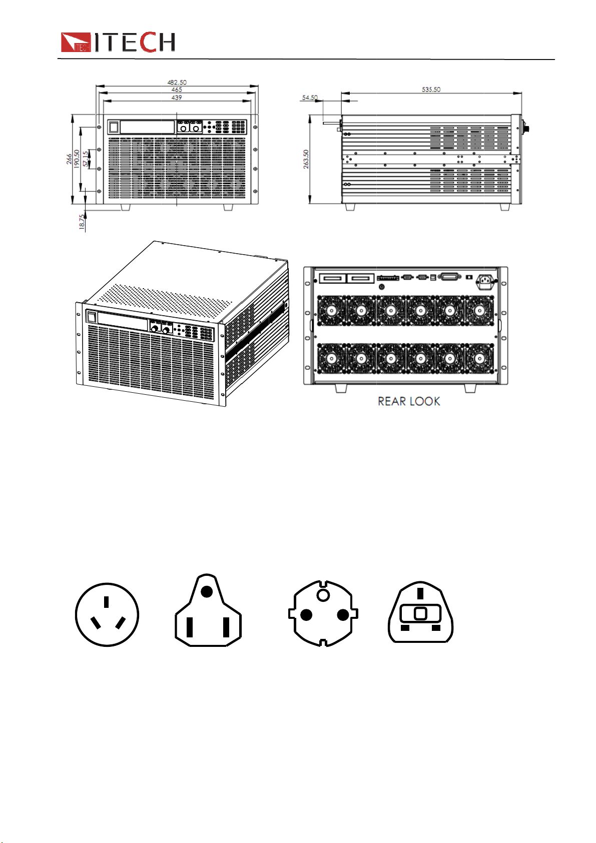
1.4.1
dimensi
Refer to
aution:C
cess
d Access
rd
anual
n testing
stallat
wing outsi
onable si
ountin
n:465
the followi
t the po
ry
ries
report
ionsit
de drawin
e of spac
Dime
mW x 26
ng dimen
er sourc
has mar
and mak
sions
.5mm H x
ion drawi
before
ed the di
sure pro
535.5mm
g:
o the cle
ension in
er ventila
D
ning
ormation.
tion condi
nit shoul
ions.
be fixed
7
User
anual
Page 8
n
o
E
n
r
h
g
n
h
h
a
2
N
0
d
o
d
1
E
t
s
IT88
0
t
n
E
w
e
0 User
Manual
1.4.2 I
Power
Connect
power c
cord. Se
N
Chi
IT-E
put co
Cord
the powe
rd was s
e followin
L
na
171
nectio
cord to t
ipped wit
figure for
E
L
United St
IT-E17
s
e IEC 32
your unit,
the part n
tes ,Cana
connecto
contact y
umber an
N
a Euro
IT-E
Uni
on the re
ur neare
ordering
L
pe
73
:minime
ar of the u
t Agent to
options.
L
United Ki
IT-E174
er(mm)
nit. If the
obtain th
N
gdom
rong
correct
User Ma
nual
8
Page 9

o
n
A
s
d
S
o
e
A
n
A
A
b
f
o
n
f
r
t
V
f
f
o
t
p
s
S
G
a
d
o
l
w
n
e
e
o
w
e
a
t
d
c
VF
O
e
0
W
d
:
X
p
t
e
e
p
o
Y
e
o
p
p
t
c
s
0
0
X
X
X
f
d
o
r
b
n
t
y
d
h
t
u
C
e
u
t
e
w
VVv
i
o
e
u
e
p
k
r
n
S
o
d
f
e
V
V
e
u
v
o
c
/
m
Y
e
.
e
y
a
e
a
IT88
0
c
e
a
s
e
n
v
w
r
i
h
p
m
t
o
o
g
M
d
p
a
c
.
c
w
c
o
u
p
e
c
a
a
s
0 User
Manual
2.1 P
2.1.1 I
succe
operate
2.1.2
Power c
St
fter tur
u
bout
bout
wer-
troduc
sful test
well.
elftest
rd should
ps
n on the
it
1S later
1S later
Ch
n self
ion
rocess in
teps
be conne
B
Syst
0.00
0.00
pter
est
icates tha
ted corre
D display
IS Ver 1.1
m Selfte
0V 0.00
CC=0.0
2 Q
units me
tly.Follo
0
t….
0A
0A
ick
t the fact
ing is the
display so
System s
FD:the fi
current va
FD:the s
power val
current/vo
alue
tart
ry specifi
etailed s
Expl
tware ver
lf check
rst line dis
lue
cond line
e and the
ltage/pow
ations an
lftest ste
nations
ion
play actu
display th
setting
r/resistan
can be
s.
l voltage
e actual
e/imped
nd
nce
Press
num
2.1.3 I
The foll
on the u
1) Veri
First, ve
panel of
the elec
2)
eri
The line
electroni
3) Veri
+
er 7
WARNIN
that has
equippe
being gr
cord is p
supply
the ele
wing mea
its:
y that th
ify that th
the electr
ronic load
y the po
voltage is
c load is s
y that th
Mo
Ver
N:XXXX
:The el
plug ap
with 3-w
unded. T
ugged in
ithout ad
ctronic
s could h
re is AC
power c
nic load.
into is en
er-line v
set to the
hipped fro
correct
el:IT88
1.XX-1.
XXXXXX
ectronic l
ropriate
ire groun
he electr
o an app
quate ca
load ca
lp you so
ower to
rd is firml
ou shoul
rgized. T
ltage set
roper val
m facory.
ower-lin
X
X
XXXXXX
oad is sh
or your l
ing type
nic load i
opriate r
inet gro
’t pow
lve some
he power
plugged i
also ma
en, verify
ing
e for you
hange th
fuse is i
Display pr
press dire
model/SN
pped fro
cation.
power co
s ground
ceptacle
nd conn
-on
roblems
supply.
nto the po
e sure th
that the el
country(1
e line volt
stalled.
ducts’s i
tion butto
software
factory
our elect
rd; the th
d only w
Do not o
ction.
ou may
wer recep
t power s
ctronic l
10VAC or
ge settin
formation
ns to che
ersion
ith a po
onic load
rd condu
en the p
erate yo
eet when
acle on th
urce you
ad is turn
220VAC)
if it’s not
You can
k product’
er cord
is
tor
wer-line
r power
you turn
e rear
lugged
d on.
when the
orrect.
9
User
anual
Page 10

If fuse is
B
C
B
C
m
a
o
g
r
p
A
A
A
A
A
A
s
e
g
a
o
C
C
C
C
C
C
u
r
o
s
t
o
h
t
h
e
n
2
e
h
0
a
t
t
Model
IT8817
IT8817
IT8817
IT8818
IT8818
IT8818
4) The
Use a fl
connect
matchin
blowout,
Fuse
T 5
T 5
T 5
T 5
T 5
T 5
ethod to
t-bladed
r on the r
fuse.(fi
lease rep
specificati
250VA
250VA
250VA
250VA
250VA
250VA
replace f
crewdrive
ar panel
ure show
lace it acc
n(110AC)
se
to open t
f the load
the fuse
rding to t
Fuse sp
T 2.5A
T 2.5A
T 2.5A
T 2.5A
T 2.5A
T 2.5A
e small p
,then you
location)
e followi
cification(
250VAC
250VAC
250VAC
250VAC
250VAC
250VAC
lastic cov
can see t
IT88
g specific
20AC)
r under th
e fuse. Pl
0 User
tion.
e AC inpu
ease use
Fuse
Manual
he
2.2 F
ont p
nel in
roduc
ion
User Ma
nual
10
Page 11

e
D
a
e
e
n
m
e
u
r
m
e
2
I
n
w
d
o
s
/
n
c
e
a
n
n
p
t
r
n
n
t
t
k
i
r
)
s
m
0
0
M
e
Th
VF
Rot
Op
Dir
Fu
power s
display
ry knob
ration mo
ction butt
ction key
itch
e(CC,CV
ns
,CR,CW)
eys
IT88
0 User
Manual
Nu
2.3 R
ber keys
ar pa
Composi
el int
e function
oduct
keys
on
Inp
t terminal
Cu
rent dete
Re
ote sens
Ext
RS
GP
Fa
US
AC
AC
rnal sign
32 comm
B commu
B commu
power sw
power in
s
tion termi
terminal,
l control i
unication i
ication in
ication in
itching(1
ut socket
al
external t
terface
nterface
erface
erface
10V/220V
(with fu
igger ter
e in it)
11
inals, 0-1
V anolog
control int
User
rfaces
anual
Page 12

F
e
t
t
t
t
t
c
m
m
q
a
l
g
e
e
t
t
t
t
r
o
r
d
m
m
e
o
o
u
s
e
e
c
t
d
t
o
v
m
r
u
d
o
e
d
o
w
d
a
r
e
e
p
e
d
y
e
s
a
a
IT88
0
g
n
a
o
s
t
e
t
t
d
l
c
0 User
Manual
2.4 V
OFF
CC
CV
CR
CW
Rmt
Addr
SRQ
2.5 K
D sta
The load
Constan
Constan
Constan
Constan
Remote
Send co
control
Serial re
y bo
us in
is in OFF
current
voltage
resistanc
power m
ontrol m
mand in
ode
uest enq
rd de
icator
state
ode
ode
mode
de
de
remote
ire
cripti
lamp
Error
Trig
Sense
Prot
Rear
Auto
*
shift
n
escri
Someth
Waiting
Remot
enable
Softwar
Externa
is open
Voltage
seleting
The ke
Shift ha
tion
ing wrong
for the tri
sense fu
e OCP st
l analog c
range aut
function i
lock func
s been pr
happene
ger signa
ction is
te
ntrol fun
omatically
open
ion is ope
ssed
tion
n
Shift(
Recal
settin
Set th
Trigg
Set th
Paus
Selec
Selec
Selec
Selec
Ensu
Contr
Up ar
composit
paramet
value
e dynami
r button,o
e parame
if neede
constant
constant
constant
value
constant
e button
l the inpu
ow button
key)
rs that ha
test para
pen trigge
ers of List
during a
current m
voltage m
resistanc
power mo
mode:
,move up
e been s
eters
function
test file
to-test
oe,set cu
de,set th
mode,s
e,set th
n/off
ords in m
ved,such
rent level
voltage l
t the resi
e power v
enu/incre
as curren
vel
tance
lue
se the se
User Ma
nual
12
Page 13

0
o
e
value
e
r
r
e
p
e
y
y
a
C
P
v
v
e
o
a
a
k
)
)
)
)
)
)
o
s
s
s
A
y
h
m
u
y
c
L
e
t
e
e
i
1
1
t
n
i
t
s
e
n
m
n
n
N
h
C
0
s
d
W
M
s
m
e
IT88
0 User
Manual
0
~
×1
2.6 C
Down
Right
mode
×1
Left a
Confi
9
numb
radix
Exit k
Rotar
Rotar
mbin
+ number
+ number
+ number
valu
arrow,mo
arrow,mo
row,mov
m button
r keys
oint key
y,exit fr
knob to
knob to
tion
1(Short
2(pragma
3(Battery
e downw
e the cur
the curso
m any op
djust the
djust the
eys
start or
uto te
)
Batter
rds in m
or to the r
r to the rig
eration co
etups by
etups by
stop shor
st functio
test funct
nu/decrea
ght when
ht when i
ndition
0 steppin
stepping
test funct
on
se the set
in set
set mode
g
ion
(Syst
+ number
+ number
m)
+ number
+ number
+ number
+ number
+CC(O
+CV(Setu
+CW(O
4(Save
5
6(Config
7(Info)
8(Lock
9(Local
P)
p)
P)
Save t
value
Syste
Config
Displa
Key lo
LOCA
OCP t
Set de
OPP t
e current
menu se
re menu
product’s
k function
key,us
st functio
ailed para
st functio
setting val
ting
etting
Model/S
d to switc
eters in
ue,such a
/Version
local an
C/CV/C
current
remote
/CR mod
etting
ode
13
User
anual
Page 14

d
d
d
d
c
e
c
t
k
C
h
c
e
t
m
e
o
c
o
c
o
c
o
c
A
c
A
c
A
c
t
)
e
)
)
r
l
~
~
Ω
%
~
%
0
1
A
≒
c
f
8
2
0
6
0
0
a
0
0
0
r
a
n
~
3
m
0
610m
0
2
m
+
3
m
r
9
t
90V≒4m
e
±0A
±
(60A
0
a
A
A
0
A
%
0
0
0
0
A
A
A
A 1
0
0
F
%
F
%
S
S
%
apte
3 Te
hnic
l Sp
IT88
cific
0 User
tion
Manual
3.1 M
M
Rated val
( 0~40
CV mo
CC mo
CR mo
CW mo
Readba
voltag
Readba
curren
Readbac
power
OPP
OCP
OVP
OTP
Short
Input
User Ma
ain te
odel
Voltag
Curren
ue
power
℃)
Minimu
setting
voltag
range
resoluti
e
accura
range
resoluti
e
accura
range
resoluti
e
accura
range
e
resoluti
accura
Range
Resoluti
k
k
nual
n
ccura
Range
Resoluti
n
ccura
Range
Resoluti
n
ccura
curren
(CC
voltag
(CV
resistan
e(CR
hnica
n 1
y ±(0.025%
n 1
y ±(0.05%
n
y 0.01
n
y
0
o
y ±(0.025
o
y
o
y
c
0.15
0
0.01
≒39.6
≒
speci
0~36A
V/36A
18V
mV
+0.05%FS)
0
36A
mA
+0.1%FS)
~10Ω
+0.08S
0.2%+
18V
1
mV
+0.025%FS
~36A
mA
±(0.05%+
±(0.2%+
≒4550W
≒130V
≒85℃
39.6A
0V
4mΩ
300KΩ
IT
817
0~1
45
0W
±(0.025%+
1
bit
45
0W
100
mW
.2%FS
Me
)
45
0W
100
mW
P
otection
specifica
icatio
0V
0
1.5V/
0~12
10
0~3
±(0.05%+
10Ω~7
0.01%+0
suremen
0~1
10
±(0.025%
0~
10
.05%FS)
.2%FS)
≒3
≒3
14
360A
60A
0V
V
.05%FS)
.1%FS)
.5KΩ
.0008S
t range
0V
V
0.025%F) ±
S
ange
6A
ion
6A
Ω
0~48
0.15V/48
0~18V
1mV
(0.025%+0.
S)
0~48
1mA
(0.05%+0.1
0.005Ω~1
0.01%+0.
0~18V
1 mV
0.025%+0.
S)
0~48
1mA
±(0
≒52.8
≒52.8
0V
≒3mΩ
IT8818
0~120V
6KW
5%F ±(0.
FS)
Ω 1
16bit
8S
6KW
100mW
.2%+0.2%
25%F ±(0.0
.05%+0.05
6KW
100mW
±(
0.2%+0.2%
≒6050W
≒130V
≒85℃
300KΩ
25%+0.05
±(0.
0Ω~7.5KΩ
0.0
1%+0.0008
S
25%+0.025
FS)
0~480A
.5V/480A
0~120V
10mV
S)
0~480A
10mA
5%+0.1%F
0~120V
1 0mV
S)
0~480A
10mA
S)
≒528A
≒528A
0V
≒3mΩ
F
)
F
Page 15

a
c
d
d
d
d
c
e
c
t
c
a
c
e
t
m
e
o
c
o
c
o
c
o
c
A
c
A
c
A
c
t
)
e
)
)
~
V0~
~
+
Ω
%
~
%
A
1
2
0
K
b
K
m
a
0
K
m
0
r
0
0
V
0
A
0
5it
.
0
m
+
)
2
A
r
2
t
2
m
0
IT88
0
5
%
Ω
0
0
M
3
5
0
1
S
5
F
S
S
F
0 User
Manual
termin
impeden
Rated val
( 0~40
CV mo
CC mo
CR mo
CW mo
Readba
voltag
Readba
curren
Readba
power
OPP
OCP
OVP
OTP
Short
Input
termin
impeden
M
odel
ue
℃)
e
e
l
e
e
e
k
k
k
l
e
Voltag
Curren
power
Minimu
setting
voltag
range
resoluti
accura
range
resoluti
accura
range
resoluti
accura
range
resoluti
accura
Range
Resoluti
n
ccura
Range
Resoluti
n
ccura
Range
Resoluti
n
ccura
curren
(CC
voltag
(CV
resistan
e(CR
0
n 1
y ±(0.025%
n 1
y ±(0.05%
n
y 0.01
n
y
0
o
y
0
o
y
o
y
c
0.3
0.03
±(0.025
≒13.2
≒
≒
12A
/12A
50V
mV
+0.05%FS)
0
12A
mA
0.05%FS)
~10Ω
+0.08S
0.2%+0
50V
1
mV
+0.025%FS
)
~12A
1
mA
±(0.05%+
±(0.2%+
≒3650W
≒530V
≒85℃
3.2A
0V
5mΩ
1MΩ
IT88
0~5
3.6
16
3.6
100
Me
3.6
100
P
17B
0V
0~12
W
3V/12
0~50
10m
±(0.025%+
S)
0~12
10m
±(0.05%+0.
10Ω~7.
0.01%+0
W
W
.2%FS
suremen
0~50
10
±(0.025%
FS
0~1
10m
.05%FS)
W
W
.2%FS)
otection
≒13
specifica
≒13
≒25
A
V
.05%F ±(
5%FS)
KΩ
0008S
t range
V
V
0.025% ±(0
0A
ange
A
ion
A
0V
Ω
0.3V/15A
0~50V
.025%+0.0
±(0
.05%+0.05
0.03Ω~10
0.01%+0.08
0~50V
.025%+0.02
≒16.5A
≒16.5A
≒20mΩ
0~15A
1mV
S)
0~15A
1mA
1 mV
S)
0~15A
1mA
±(0.
±(
0V
IT8818B
0~500V
5KW
%F
±(0.02
±(0.0
FS)
1
16bit
S
5KW
100mW
0
.2%+0.2%F
5%F ±(0.02
5%+0.05%
5KW
100W
.2%+0.2%F
≒5050W
≒530V
≒85℃
1MΩ
0~150A
V/150A
0~500V
10mV
5%+0.05%
0~150A
10mA
%+0.05%F
Ω~7.5KΩ
0.0
%+0.0008
0~500V
10 mV
%+0.025%
0~150A
10mA
FS)
S)
≒165A
≒165A
≒20mΩ
S)
)
S
)
0V
15
User
anual
Page 16

d
d
d
d
c
e
c
t
c
a
c
e
t
m
e
o
c
o
c
o
c
o
c
A
c
A
c
A
c
t
)
e
)
)
~
~
~
+
Ω
%
~
1
%
≒
8
2
0
6
0
0
a
+
0
0
r
0
6
m
0
010m
.bit
0
21 m
+
)
0
m
r
6
t
60V≒3m0A
±0A
±
±0A
0
A
0
%
0
8
0
0
C
1
0
1
F
5
F
≒
F
)
S
F
Rated val
( 0~40
CV mo
CC mo
CR mo
CW mo
Readba
voltag
Readba
curren
Readba
power
OPP
OCP
OVP
OTP
Short
Input
termin
impeden
M
odel
ue
℃)
e
e
e
e
k
k
k
l
e
Voltag
Curren
power
Minimu
setting
voltag
range
resoluti
accura
range
resoluti
accura
range
resoluti
accura
range
resoluti
accura
Range
Resoluti
n
ccura
Range
Resoluti
n
ccura
Range
Resoluti
n
ccura
curren
(CC
voltag
(CV
resistan
e(CR
0
n 1
y ±(0.025%
n 1
y ±(0.1 %
n
y 0.01
n
y
0
o
y
0
o
y
o
y
c
±(0.025
≒66A
0.18
0
0.01
0.
≒
600A
V/60A
18V
mV
+0.05%FS)
0
60A
mA
0.1%FS)
~10Ω
+0.08S
0.2%+
18V
mV
+0.025%FS
)
~60A
1
mA
±(0.05%
±(0.2%+
≒4550W
≒130V
≒85℃
66A
0V
3mΩ
300KΩ
IT8
0~1
45
0W
±(0.025%+
1
45
0W
100
mW
Me
0.1%FS)
45
0W
100
mW
P
specifica
17C
0V
0~6
1.8V/
0~12
10
0~6
±(0.1%+0
10Ω~7
0.01%+
.2%FS
suremen
0~1
±(0.025%
0~6
10
.2%FS)
otection
≒6
≒6
00A
0V
V
.05%FS)
.1%FS)
5KΩ
.0008S
t range
0V
V
0.025%F
S
ange
ion
0A
Ω
IT88
0~72A
0.18V/72
0~18V
1mV
(0.025%+0.
FS)
0~72A
1mA
(0.1%+0.1
0.005Ω~1
0.01%+0.0
0~18V
1 mV
(0.025%+0.
%FS)
0~72A
1mA
±(
≒79.2A
≒79.2A
0V
≒2.5mΩ
0 User
IT8818
0~120V
6KW
1
5%
±(0.02
FS)
Ω 1
16bit
S
6KW
100mW
.2%+0.2%
025 ±(0.02
.05%+0.1%
6KW
100mW
±(
0.2%+0.2%
≒6050W
≒130V
≒85℃
300KΩ
.8V/720A
0~120V
5%+0.05%
±(0.
0.0
0~120V
FS)
Manual
0~720A
10mV
0~720A
10mA
%+0.1%FS
Ω~7.5KΩ
%+0.0008
S
10mV
%+0.025%
)
0~720A
10mA
S)
≒792A
≒792A
0V
2.5mΩ
S)
S
User Ma
nual
16
Page 17

u
y
t
e
O
O
n
a
t
n
0
y
s
m
:
a
V
V
e
°
a
r
d
y
u
c
0
0
°
a
a
t
s
°
a
s
r
°
T
p
IT88
0
M
0 User
Manual
3.2 S
Memor
Sugges
AC pow
Option
Option
Cooling
Fans
Fan-co
Temper
Fan sta
Operati
0 to 40 °
Storage
-20 to 7
Humidit
Indoor u
pple
capacity
ed calibr
r input s
pt.1:
220
pt.2: 11
method
trol temp
ture 35
e Sc
g tempe
C
temperat
°C
e,humi
0
entar
100 gro
tion freq
cale(sele
±10% 5
±10% 5
rature
C 50
le 1 sc
ature
ure
ity≤ 80%
char
ups
ency:1
table by
Hz/60Hz
Hz/60Hz
C 70
le 2 Sc
cteri
ime/yea
witch on
C 80
le 3 O
tic
the rear
C
P.load off
anel)
17
User
anual
Page 18

C
n
p
a
s
t
e
f
g
a
o
e
N
P
P
e
e
m
o
p
G
c
a
a
a
a
o
t
h
o
a
n
u
t
n
c
o
a
e
c
y
e
2
o
d
t
e
n
m
e
F
n
m
e
o
i
y
o
e
e
d
p
C
V
(
t
o
s
a
c
i
o
o
t
a
N
m
(
n
p
n
s
o
d
o
t
d
o
c
e
a
e
h
m
m
e
r
o
o
u
IT88
0
t
t
e
t
a
c
e
d
e
o
s
t
0 User
Manual
We will i
several
Loc
Con
Inpu
Syst
Con
Trig
Dyn
List
Sav
VO
OC
OP
Batt
Prot
Key
Ter
lock functi
hap
troduce t
arts.
l/remote
tant oper
control
m menu
ig menu
er functio
mic test f
peration
/Recall fu
function
test func
test funct
ry test fu
ction fun
inal on re
er4
e functio
peration
tion mod
nction
nction
ion
ion
ction
tion
n
r panel
uncti
s and ch
ode swit
s
on a
racteristic
hing
d C
of EL co
arac
pletly in
eristi
his chapt
r from
4.1L
The
can be s
Local op
menu o
via the
panel ca
4.2 O
The ele
1: const
2: const
3: const
4: const
4.2.1C
In this m
program
cal/R
electroni
witched b
eration m
eration. R
PIB、RS
n be used
perati
tronic loa
nt curren
nt voltag
nt resista
nt power
nstant
ode, the e
med valu
mote
load prov
Local ke
ans contr
emote op
32、USB
, In remot
n mo
can be o
mode (C
mode(C
ce mode
ode(CW
curren
lectronic l
regardle
perat
des two c
on the fr
l the elec
ration me
or Ether
control
es
erated in
)
)
CR)
)
mode
ad will si
s of the in
on m
ntrol mo
nt panel
ronic loa
ns contr
et interfa
ode,the k
the followi
CC)
k a const
ut voltag
de
e: Local
r SCPI co
via the k
l the elect
e.in local
ys can n
ng five m
nt current
. See fig
ode and r
mmand.
ys on the
onic load
mode, all
t work.
des:
in accord
re4-1.
mote mo
front pan
through c
he button
nce with
e, which
l and the
mputer
on front
he
User Ma
nual
18
Page 19

C
s
v
C
h
h
r
t
h
t
t
n
d
Lcu
e
m
i
a
i
1
(
l
u
C
o
a
C
r
o
p
e
o
u
R
e
g
u
o
c
t
t
t
IT88
0
n
s
o
t
M
o
s
I
oad
rrent
Load in
CC
Figure 4-
ut volta
mode
CC mod
eV
Set
ing curre
0 User
nt
Manual
4.2.2
In thi
source
4.2.3
In t
below, t
See figu
onstan
mode, t
oltage to t
Loa
input v
onstan
is mode,
e electro
e 4-3.
voltag
e electron
he progra
V
oltage
resist
he electro
ic load wil
mode
ic load wil
med val
Load cu
CV m
F
gure 4-2
nce m
nic load w
l linearly c
CV)
attempt t
e. See fig
rent
de
V mode
de(C
s equival
hange the
sink eno
re 4-2.
Se
vol
I
)
nt to a c
current a
gh curre
ting
age
nstant re
cording t
t to contr
istance, a
the input
l the
shown
voltage.
F
gure 4-3
R mode
19
User
anual
Page 20

C
h
A
n
s
S
t
f
c
s
t
y
U
t
t
t
o
o
m
n
s
a
r
r
o
m
w
n
e
O
n
n
t
e
n
(
e
(
a
e
i
e
u
c
n
e
s
Z
-
a
e
v
d
g
n
n
p
e
o
C
e
E
A
o
a
p
a
m
e
o
t
o
IT88
0
w
S
,
h
o
e
a
g
o
t
t
p
t
o
4
n
r
u
t
a
e
e
0 User
Manual
4.2.4
In t
below.
4.3 In
onstan
is mode,
s the inpu
put C
power
he electro
voltage i
ntrol
mode
nic load w
crease,th
Figure4-
CW)
s equival
current
4 CW mo
nt to a c
alue will d
e
nstant po
ecrease,
er, as sh
ee figure
wn
-4.
4.3.1 I
You
buttoni
If input
4.3.2
The
switch
won’t a
original
The
range a
current i
constan
4.4 S
Press
SYSTE
MEN
User Ma
put sw
can contr
lit,that
have bee
hort op
load can
o short st
fect the p
set state.
actual cu
tive when
120% of
voltage t
stem
+nu
Ini
M
Po
nual
itch op
l the On/
eans the i
opened,i
eration
imulate a
te in local
esent set
rent of th
the short i
the curre
be 0V
menu
ber 5 to
tialize
er-ON
ration
ff state v
put is op
dicator la
short circ
operation
ing. When
electroni
s turned o
t range. I
Syst
nter the
INITIALI
NO
YES
POWER
RST(def
SAV0
a pressin
ned,whe
mp “off” o
it at its in
mode(op
turn off th
in short
n. In CC,
CV mod
m)
ystem me
E SYST
ON PAR
ult)
20
the
b
the VFD
ut. You c
rate with
e short st
peration d
R or CW
, short m
nu
M?
Keep the
Reset all
MENT
Set the l
default s
Set the l
button
utton is lig
display w
n press
ront pan
te, the lo
epend on
ode, the
ans settin
current c
configura
ad’s inpu
ate when
ad’s inpu
when
ted,the i
uld be da
+ n
l). Short o
d returns
the mode
maximum
the load’
nfigure
ion to def
state to b
ower on
state to b
put is off.
k.
mber
1 to
peration
o the
and
short
s
ult
the
that of
Page 21

u
o
o
u
KTrMe
D
m
o
a
F
m
m
o
d
e
F
(
y
V
L
R
u
d
(
(
Y
a
e
e
a
C
C
D
T
s
k
h
g
t
o
M
C
E
N
e
o
0
h
h
S
a
t
r
M
e
-
D
h
h
S
(
o
d
e
t
t
i
o
IT88
0
u
f
o
d
g
e
m
0
1
s
e
n
n
c
r
o
e
v
O
M
n
c
e
i
c
P
,
F
m
o
0 User
Manual
*Knob f
put the l
when yo
B
Com
Pr
nction: re
ad to OF
u turn the
zzer
nob
igger
mory
ispl
unication
tocol
l-time up
state, th
load to O
BUZZE
On(defa
Off
LOAD O
Update(
Old
TRIGGE
Manual
External
Hold
Bus
Timer
MEMOR
Group=
DISPLA
On
Off(def
COMMU
RS232
Move th
direction
select th
comunic
interface
USBTM
GPIB
PROTO
SCPI(
Extend-
ate mean
settings
F state, t
STATE
lt)
N KNOB
efault)
R SOUR
Def)
Y
0-9)
ON TIM
ult)
NICATIO
keys to
tion
OL
efault)
able
after you
eep for th
e settings
SAVE
Enable t
Disable t
ODE
Set to re
No upda
E
Manual t
Trigger b
Trig:IM
GPIB BU
Trigger b
0: repres
group 11
R
Enable t
Disable t
4800,8,
9600
19200
38400
57600
115200
Address
SCPI pr
Extende
with othe
adjust th
latest se
will keep
set when
Set the b
e buzzer
e buzzer
et the kn
l-time up
e
Set the tri
igger
y external
availabl
S trigger
y timer
Operated
to recall 1
memories
nt group
20,and
isplay th
e functio
e functio
elect the
interface
communi
N (no pa
O (odd)
E(even)
0-31)
tocol
SCPI pr
r units
paramet
up. If you
he old set
power on
zzer state
unction
function
b functio
ate
ger sour
signal
ode
with Reca
0 groups
-10;1:r
o on
loading t
communi
when
ate with
ity), 1
CTS/RTS
XON/XO
tocol,co
r by knob
choose “n
tings.
e
ll button
present
me
ation
C
NONE
F
patible
and then
update”,
4.5 C
Press
CONFIG
MENU
nfig
+nu
V
enu
ber 6 ke
n
Confi
to enter
OLTAGE
iving
P
)
he config
ON
V
int= 2V
21
menu.
Set t
n point liv
set the V
he load’s
ng state,
n value
on point
N /OFF
User
anual
Page 22

Pro
t
s
L
-
o
L
P
M A
P
T
MVT T
F
COO
R
S
E
o
A
O
N
VOL
E
E
r
O
S
R
o
e
W
t
e
I
n
a
s
e
1
e
e
o
U
v
e
A
i
e
A
i
l
n
n
s
nDis
n
oDisco
o
w
W
a
u
t
t
u
w
e
O
f
s
o
G
o
o
e
V
e
0
6
a
u
t
f
f
f
n
r
n
0
O
r
d
t
a
w
e
n
n
a
t
a
v
E
n
)
a
n
P
g
e
e
n
c
o
v
e
v
m
m
e
n
g
Mea
CR-
Remote
Ext-Pr
ect
ure
ED
Sense
gram
atch
P
ROTECT
ax-P
M
-Limit
- Limit
ime
EASURE
-Range
imeV1
TIM
imeV2
TIM
ILTER
Ave
R LED M
n
ff
EMOTE
TATE
On
Off
XTNAL P
On
Off
int= 2V
MENU
X PO
CU
RRENT L
On en
Poi
Del
Off di
P
WER L
Point=
Delay=
O
-TIMER
On e
D
Off d
MENU
TAGE A
R VOLT
Po
R VOLT
Po
age Cou
DE
ENSE
OGRAM
V
S
Poin
S
S
S
V
On v
Off
T
T
Fi
E
Di
E
E
c
n point lat
set the V
tup hard
ER
=149.99
tup softw
MIT
able the f
t=30A se
y=3S set
able the f
t the soft
IMIT
50W set t
3S set th
t LOAD
nable the
lay=10S
isable the
ltage aut
TO RAN
oltage aut
oltage aut
st the volt
GE1 s
nt=0.000
st the volt
GE2 s
nt=120.0
ter functio
t=2^(2~1
Imit
able the f
+CV
able this
Rem
able this
able the
Exte
able exte
ntrol funct
ale exter
ntrol funct
IT88
ch state,
n value
are powe
set har
re curren
nction
the softw
he softwa
nction
are powe
he soft po
soft pow
N timer
unction
et LOAD
function
range fu
E
range fu
range fu
age rise/f
t the star
age rise/f
t the end
n
) the e
te the L
nction(i
o set Vd
unction
ote sense
unction
unction
al analog
nal 0-10V
ion
al 0-10V
ion
0 User
N /OFF
protectio
ware OP
protectin
re OCP l
re OCP d
r protectio
er prote
r protecti
ON timer
ction
ction on
nction off
ll time
voltage l
ll time
voltage le
erage nu
D in CR
CR mod
function
signal fu
analog si
nalog sig
Manual
value
state
vel
lay
level
tion level
n delay
alue
vel
el
ber set
ode
,press
ction
nal
nal
User Ma nual
22
Page 23

r
T
g
d
n
T
r
b
l
a
n
n
g
o
/
a
s
s
a
e
s
C
o
f
t
n
t
s
k
n
o
h
n
a
e
a
e
n
o
c
o
e
s
e
n
L
n
g
r
G
o
a
f
t
A
h
d
o
n
h
e
m
h
h
n
h
a
P
v
a
o
m
f
m
n
a
o
r
o
e
l
o
h
h
e
m
p
p
u
s
e
s
k
m
n
g
l
o
y
a
t
r
e
IT88
0
e
r
t
o
a
e
v
l
h
e
e
b
n
e
g
M
e
s
e
b
e
a
o
a
n
e
w
0 User
Manual
4.6 T
4.6.1
Trig
triggere
Synchro
should fi
4.6.2
keyboa
will ena
Externa
of the m
a low pu
Bus trig
comma
Timer tr
operatio
Trigger
the trig
trigger
igger
rigger f
er opera
output a
ously trig
rst select
rigger
d(
le a trigge
trigger s
in frame i
lse(>10u
ger:whe
d(GET
igger:w
periodly.
maintena
er comm
peration.
uncti
unction
ion can b
d list outp
ger the te
rigger sou
ource
ey)trigg
r operatio
ignal(TT
s trigger i
S)to the
bus trig
r *TRG)f
en timer t
ce:when
nd(TRI
n
used in t
ut. The el
ted instru
rce.
r:when t
.
level):t
put termi
internal, t
er is avail
rom the G
igger is a
trigger m
:IMM)fr
e followin
ctronic lo
ent, bef
e keyboa
e 1st pin
al, when
e load wil
ble, as s
IB port, t
ailable, t
intenanc
m the co
g operatio
d have 5
re enable
d trigger
f the 8 pi
xternal tri
enable a
on as the
e load wi
e electron
is availab
municati
ns: transi
inds of tri
the trigge
ode is ac
s connect
ger sign
trigger op
load recei
l enable a
ic load wil
le, only w
n port, th
nt pulse o
gger mod
function,
ive, pre
r on the r
l is availa
ration.
ve a trigg
trigger op
enable a
en the lo
load will
utput,
s to
users
s ,
ar panel
le, input
eration.
trigger
d receive
enable a
4.7 A
Tr
levels, a
the tran
the oper
paramet
The tran
4.7.1
Und
continu
B tran
nsient op
might be
ient oper
tion, you
rs includ
ient testi
ontinu
er the con
usly swit
sient
ration en
required
tion menu
should se
: A level,
g modes
us mo
tinuous m
h betwee
perati
bles the
or testing
from the
the para
width, B
ave 3 kin
e(Co
de, when
the A/B l
T
ons
odule to
power su
ront panel
eters ass
level, B w
ds: contin
tinuou
the transi
evels pre
eriodicall
plies dyn
( by key
ociated wi
idth, and t
ous, puls
)
nt test is
et
switch b
mic prope
),
h transie
ansient t
d, or tog
turned on,
tween tw
rty. We c
efore you
t operatio
sting mod
led.
the load
load
n enter
turn on
. The
s.
ill
23
User
anual
Page 24
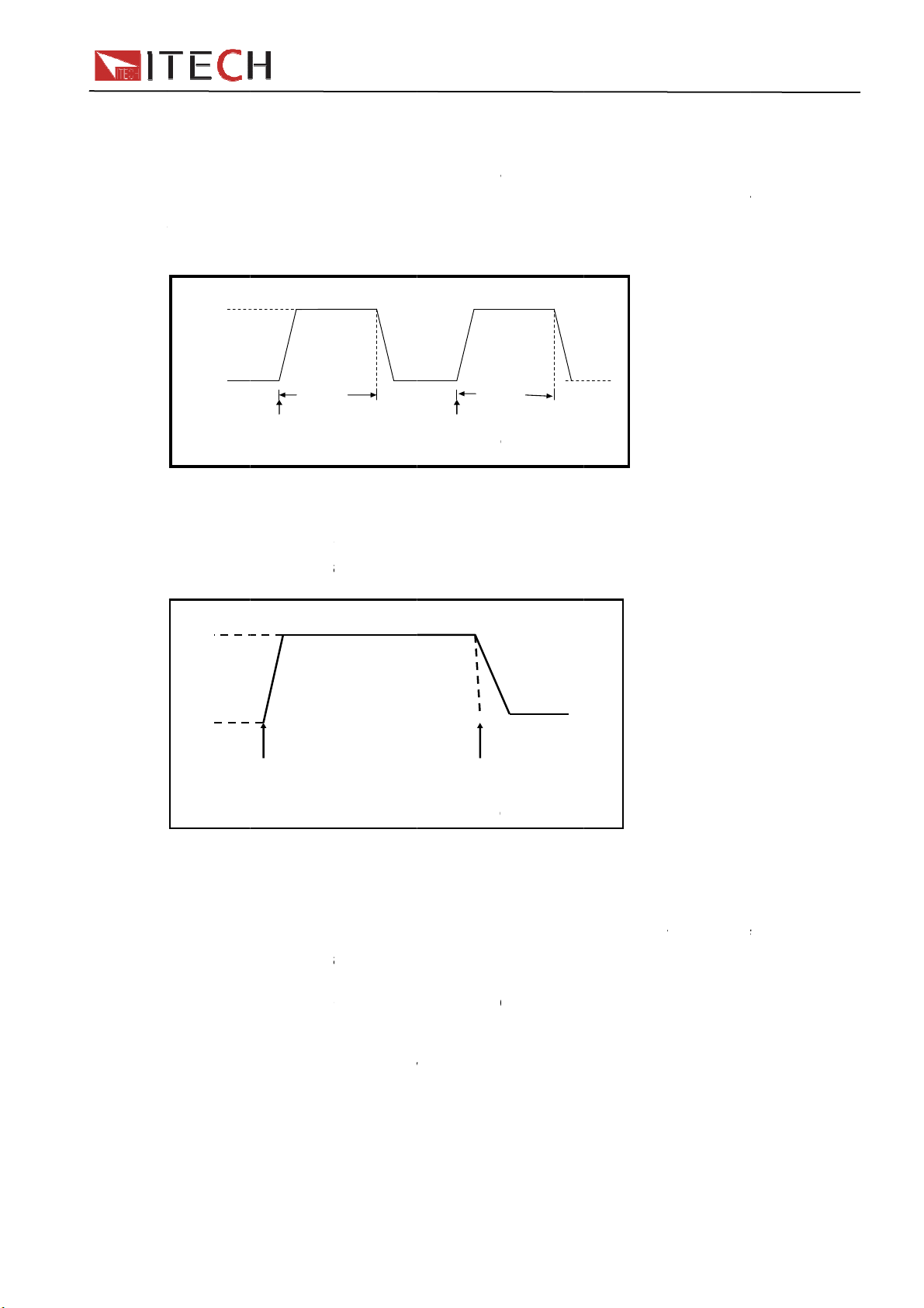
P
d
d
m
t
t
T
o
i
w
w
t
e
e
e
m
o
o
c
w
s
e
a
d
2
i
o
T
u
d
T
t
r
a
c
o
a
e
s
y
a
d
D
T
m
d
p
p
e
h
m
l
e
y
f
o
t
t
t
w
w
o
h
o
o
e
m
u
t
h
o
m
W
G
o
w
e
A
T
h
y
w
d
n
r
t
IT88
0
r
h
f
e
n
h
T
v
2
o
e
m
r
e
f
t
g
h
0 User
Manual
4.7.2
In pulse
keyboar
width ti
receive
transien
4.7.3
In t
a trigger
current
ulse m
mode, y
. The ele
e, then it
he pulse
operation
10A
5A
oggled
ggle mod
ng signal
aveform i
de(P
u can set
tronic loa
ill switch
ignal. The
TW
10m
TRIG
Pulse
mode (
, the elec
fter the t
n toggle tr
lse)
A/B level,
will auto
to B level,
following
s
Transien
oggle
ronic load
ansient o
nsient o
A/B width
atically s
it won’t s
picture sh
T
10
TRIG
Operati
)
will switc
eration is
eration.
and A/B s
itch to A
ith to A l
w the cur
D
s
n
between
enabled.
lew rate vi
level, afte
vel until t
rent wave
level/B l
he followi
a mainfra
maintaini
e the inst
orm in pul
vel when
g picture
e
ng A
ument
se
receiving
show the
4.8 Li
List mod
timing,
running
Generat
trigger r
paramet
width ti
saved in
In list op
signal, u
signal.
User Ma
10A
5A
st ope
e lets you
hich may
est seque
complex
source, e
rs of List
e(0.0000
non-volat
eration m
ntil the list
nual
TRG
oggled
ration
generate
be synchr
nces with
sequenc
iting the
operation
s~3600s)
le memor
de, the lo
operation
ransien
(LIST)
omplex s
nized wit
minimu
s to comp
tep value
include th
and ever
, used to
d begin t
is comple
TR
Operati
quences
internal
amount
ete compl
, width ti
name, n
step’s se
ast recall.
enable t
ed or the
24
n
of input c
r external
f overhea
x tests b
e and sle
mber of s
value an
Users ca
e list ope
instrumen
anges wit
signals.
d.
editing LI
rate of e
teps(max
slew rate
edit up t
ation onc
receive a
rapid, pr
his is use
ST: Selec
ery step.
-84), sin
. The list fi
7 groups
receive t
nother trig
cise
ul when
different
The
le step
le can be
list file.
e trigger
ger
Page 25

a
e
e
a
m
v
s
L
s
Y
r
o
s
m
V
s
f
u
d
e
o
v
m
f
h
d
u
o
u
u
2
u
a
d
e
l
e
c
:
s
f
n
e
e
d
l
.
n
s
o
t
n
t
a
t
A
V
+
(
e
o
a
d
v
G
f
t
q
n
o
4
m
n
0
n
m
r
n
s
n
a
s
n
),
y
G
u
u
h
IT88
0
e
VFD
u
t
e
e
o
o
M
r
A
A
c
o
c
a
u
a
0 User
Manual
4.9 S
W
paramet
capacity
fast rec
Save an
For exa
SAVE
1、set all
9 to sa
2、Pres
RECAL
1、Pres
to recall
Note:
function
Trigg
0
ve an
can save
rs includ
is 100 gr
ll.
d recall o
ple: the
the para
e data to
key
key
the data t
ou shoul
to help yo
r
123
List cou
reca
some oft
s working
ups. You
peration
oltage pro
eter,pre
ile 9
to con
,press
at is save
combin
recall th
Ope
mode,vol
vided is 6
ration
d in the m
45
t=1
List se
l func
n-used p
an use S
s
irm
umber 9
the Mem
saved p
Li
uence
ion
rameters
age/curre
VE key t
and the l
number
recall fro
mory
ry functio
rameters.
t count=2
in the non
t value a
save par
oad work
and the
9th file
(in the s
volatile m
d so on.T
meters, p
in CC 1A
5.8949V
5.89W
5.8949V
5.89W
5.8949V
5.89W
stem men
mory,the
he memo
ress
display
0.99994A
SAVE 9
0.99994A
cc=1.000
0.99994A
cc=1.000
) with Re
y
key to
all
Memo
When y
in the sy
Group0
datas sa
y functi
u want to
tem men
eans yo
ved in 11-
n:
recall the
first.
can reca
0 groups
ata save
l datas sa
Group2-
in the me
ed in 0-1
roup9 ca
mory, you
groups.
be concl
should se
roup1 m
ded in th
the mem
ans you
same m
ry group
an recall
nner.
4.10
Von/Vof
reaches
Voff val
Pre
s
to control
the Von v
e, the loa
ON f
nctio
+number
the input
lue, the l
’s input s
9 to enter
tate on/o
ad’s inpu
ate is off.
configure
f for elect
state is o
25
enu ,yo
onic load.
. When t
can set v
When the
e input v
ltage val
input volt
ltage reac
User
e
ge
hes the
anual
Page 26
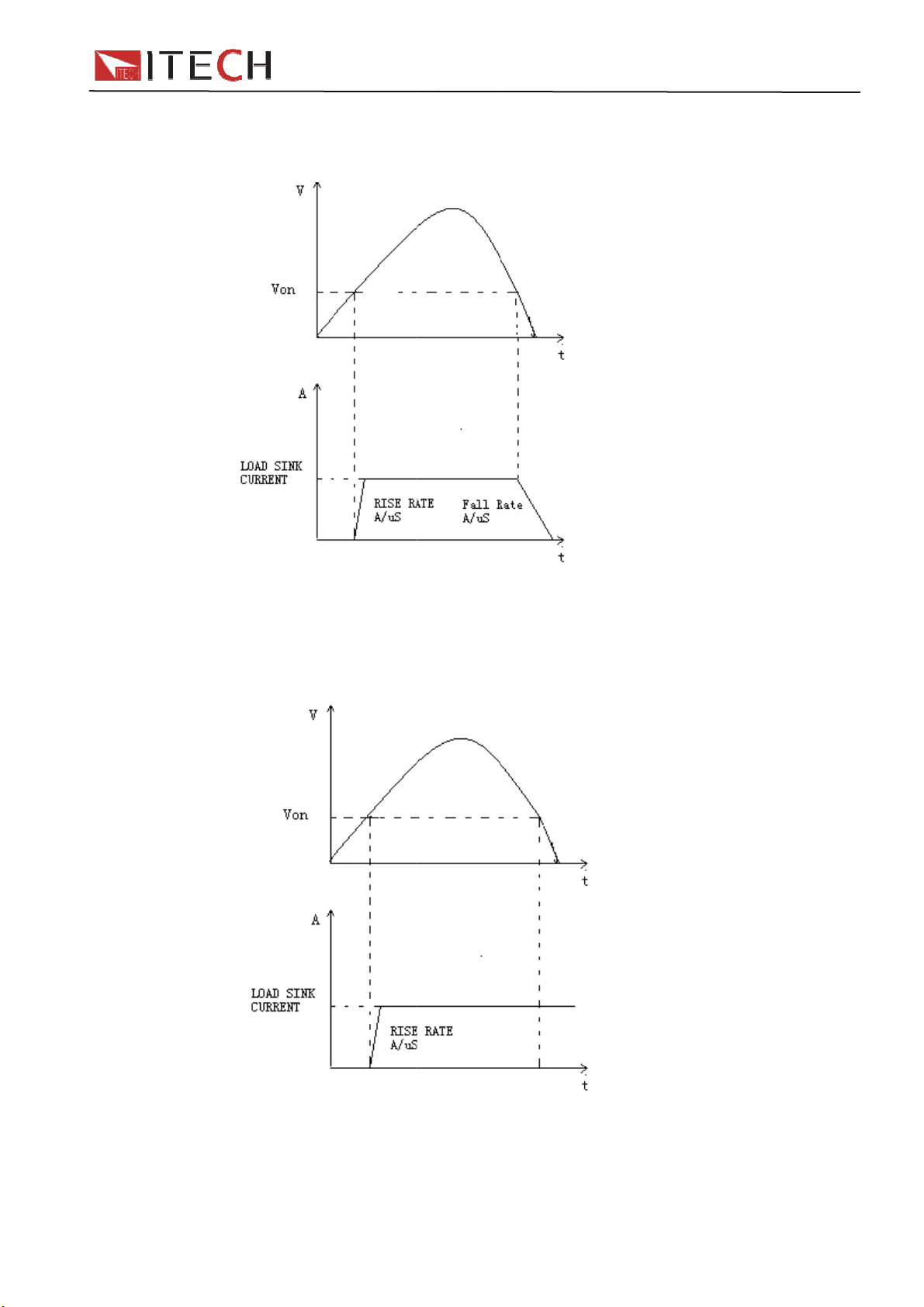
The
e
n
n
y
e
n
N
a
,
t
,
r
O
e
g
W
o
s
v
g
r
d
p
w
L
s
V
d
0
n
V
g
g
d
Wh
it means
re is two t
n you sel
working i
pes of Vo
ct Living
latch sta
n working
that mea
e when th
modes: Li
ns workin
e voltage
ing and
in living
each the
IT88
atch.
tate; whe
on point.
0 User
you sele
Manual
ct Latch,
When e
input of
than Vo
able LIVI
electronic
unload v
VON L
G mode
load is tu
lue, input
IVING stat
as volta
ned on.
is turned
load work
e rise an
hen the
ff.
ing mode
is higher
ower sup
than the
ply’s volta
on loadin
e fall an
voltage,
is lower
V
N LATCH
User Ma
nual
tate load
26
orking mo
e
Page 27

n
o
o
O
s
e
y
,
e
y
e
O
s
e
y
t
m
y
e
s
e
s
t
e
n
n
a
o
l
s
t
e
o
n
P
o
o
n
c
e
c
i
e
n
P
C
a
V2:V3:C
O9:M
M
e
c
e
p
o
w
P
P
h
d
u
n
r
g
e
e
n
n
n
=
g
u
C
=
e
W
o
v
r
e
r
h
u
e
s
0
0
0
)
e
e
e
c
r
e
u
h
o
u
w
o
s
t
e
e
eSeSeSe
e
e
p
o
a
s
t
u
t
e
t
IT88
0
a
u
a
w
c
o
r
u
r
r
p
c
a
o
o
t
o
w
c
r
M
g
b
O
t
t
d
e
e
e
e
P
t
F
e
0 User
Manual
When e
of electr
Von unl
4.11
OCP te
work aft
intervals
voltage(
is in the
contrary
compar
Press ke
Press k
OCP
TEST
able Von
nic load i
ad value,
CP t
t proces
r a delay
.Simultan
ou need t
current ra
the curre
OCP volt
t
y
Run
Reca
Edit
LATCH, v
turned o
input won’
st fun
:When th
ime.The
ously,unit
o set).If it
ge you’v
t will conti
ge with i
start OC
+CC(O
l
OCP
OCP
Rec
OCP
1:
4:S
5:S
6:S
7:E
8:
10:
Sav
ltage rise
. When t
t be turne
tion
input volt
urrent val
will judge
s,then the
set.Withi
nue to inc
put volta
P)to ent
TEST
TEST
ll OCP Fil
TEST
oltage on
oltage on
urrent Ra
tart Curre
tep Curre
tep Delay
nd Curren
CP Volta
ax Trip C
in Trip
OCP File
and is hig
e power s
off.
age has r
e will inc
whether t
present c
this rang
ease with
e too.
r OCP te
Ru
=1
level=0.0
Delay=0.0
ge=0.000
t=0.000A
t=0.000A
0.00S
t=0.000A
e=0.000V
rrent=0.0
urrent=0.
1(1-5
Re
her than t
upply’s vo
ached Vo
ease by a
e input v
rrent val
,the test
in the cut-
t function
n OCP te
call OCP
0V
0S
A
0A
00A
e Von lo
ltage fall a
n point, c
step size
ltage is lo
e will be
ill Pass
ff current
setup inte
t file
est file(1
S
t Von val
S
t voltage
S
t current
t start cu
t step cu
t the ste
S
t cut-off
S
t OCP v
per limit
u
L
wer limit
S
ve OCP
ding volta
nd is lowe
rrent will
t regular
er than
ompared
r will Faul
range.An
rface
-5)
e
on delay t
range
rent valu
rent valu
delay tim
urrent
lue
f OCP val
f OCP va
est file
e, input
r than
egin to
CP
o see if it
.On the
then
ime
ue
lue
4.12
OCP te
work aft
intervals
voltage(
is within
the con
then co
Press ke
Press k
PP te
t proces
r a delay
.Simultan
ou need t
the curre
rary,the c
pare OP
y
st fun
:When th
ime.The
ously,unit
set).If it
t range y
urrent will
voltage
t
start
+
CW(OP
OP
tion
input volt
ower valu
will judge
is,then th
u’ve set.
continue t
ith input
test.
)to ente
age has r
e will incr
wether th
present
ithin this
increas
oltage too
the OPP f
27
ached Vo
ase by a
input vol
urrent val
ange,the
within th
.
nction tes
n point, p
tep size a
age is lo
e will be
est will Pa
cut-off cu
setup inte
wer will b
t regular
er than O
ompared
ss or will
rrent rang
face.
User
gin to
P
o see if it
ault.On
.And
anual
Page 28

P
T
B
y
i
h
r
a
d
s
e
T
o
P
s
F
t
n
aEdi
y
e
u
u
w
o
oCap
T
u
s
c
a
V2:V3:C4:S5:S6:S7:E8:O
M
:
e
h
d
c
e
t
s
b
3
S
S
S
S
S
S
n
p
y
h
e
n
r
r
=
=
g
o
P
g
e
a
n
e
o
g
o
b
o
r
e
e
p
u
e
0
0
0
V
0
)
y
e
n
e
h
a
n
n
h
r
n
s
s
t
U
o
k
s
g
w
w
f
f
a
b
u
,
IT88
0
e
e
r
p
p
P
o
o
t
a
e
a
e
a
b
n
m
a
f
e
t
n
a
a
v
e
e
p
P
p
a
e
0 User
Manual
OPP
Ru
Rec
ll
OP
TES
t
OPP
Rec
OPP
1:
9:
10
Sav
TEST
TEST
ll OPP Fil
TEST
oltage on
oltage on
urrent Ra
tart Powe
tep Powe
tep Delay
nd Power
PP Volta
ax Trip P
Min Trip
OPP File
R
=1
level=0.0
Delay=0.
ge=0.00
=0.000W
=0.000W
0.00S
0.000A
e=0.000
wer =0.0
ower =0.0
=1(1-5
R
n OPP te
call OPP
0V
0S
A
0W
00W
t file
est file(1
S
et Voltag
S
et Voltag
S
et the wor
S
et the sta
S
et the ste
S
et the ste
S
et the cut-
S
et the OP
pper limit
L
wer limit
S
ave OPP
-5)
on value
on delay
king curre
t power v
power v
delay tim
off power
value
f OPP va
f OPP va
est file
ime
t range
lue
lue
e
alue
lue
lue
4.13
Capacit
Electron
in off sta
checks t
procedu
spare c
displaye
it’s nece
Press k
STO
CONDI
Operati
1)
atter
test
c load us
te. The ac
e accum
e, you co
pability of
in windo
sary to d
y
V
P
ION
n :
ress key
disc
s CC mo
cumulator
lator whi
ld see th
accumula
. This te
the test
+number
ltage
ability
imer
to
argin
e to do th
have too l
h is near t
accumul
or. If con
t can refl
efore you
TOP C
top Volta
TOP C
top Capa
TOP C
top Time
turn off th
test
capabilit
ow voltag
o one rati
tor voltag
ecting wit
ct the reli
change a
ndition
e Set
ndition
ility Set
ndition
e load, co
the cut-of
the cut-of
Set
the disch
test. Ma
, electron
g or in in
, dischar
PC soft
bility and
other ne
nect the
e a progr
ic load int
ecurity st
e current,
are, disch
using tim
accumul
voltage
capacity
rge time
attery to
m to set t
rmits test
te. In testi
discharg
arge curv
of accum
tor.
e tested,
he voltag
if system
ng
time and
could be
ulator. So,
ress
+n
mber 3 i
elect on
2)
or the fir
o input off
User Ma
nual
e of the 3
t means:
,V
FD displa
to
state.
onfirm,w
CC mod
testing m
ress key
“Stop Ca
en the ca
to enter t
ans acco
+
pability =
acity fall
28
e battery
ding to yo
umber 3
Ah”,set
to the val
dischargi
r test de
select C
the cut-of
ue set, th
g function
ands.
pability,
capacity,
load will
menu,
ress key
ress key
uto turn
Page 29

F
v
V
a
P
P
P
a
p
e
n
n
i
e
e
n
o
u
o
e
n
s
i
.
r
a
e
r
e
m
o
c
s
e
h
a
a
C
t
(
t
l
m
V
c
O
a
e
r
a
n
C
c
o
e
e
c
e
a
v
n
s
a
s
f
e
u
o
c
o
n
e
e
F
e
a
P
t
i
m
w
e
t
e
t
k
.
o
,
s
s
e
n
r
/
c
o
t
d
t
e
i
s
e
p
t
h
h
d
f
A
w
n
V
e
u
m
d
e
n
h
t
c
V
w
n
v
T
a
d
e
e
r
a
i
e
e
s
w
P
e
r
e
o
g
a
v
p
n
b
r
o
v
d
m
s
e
O
t
C
s
IT88
0
o
s
,
t
r
i
z
i
n
e
t
T
t
t
r
b
v
i
a
M
p
s
t
,
P
e
t
P
e
m
m
E
e
t
w
H
F
3)
or the se
oltage, th
4)
For the t
FD displ
utomatic
5)
ress key
6)
ress “ES
,V
FD will di
to
ond mea
tart the b
load will
ird mean
y ”Stop Ti
lly turn of
to
”, quit th
s:press
play”Stop
ttery test
auto turn
: press
mer= S”
after the
start to te
battery t
ey
Voltage=
When th
ff the inp
+nu
set the
etting tim
t
st mode.
+numbe
”,set th
battery v
t.
ber 3,se
ischargin
.
3,select
cut-off v
ltage fall
lect Timer
time, the
0 User
Voltage,
ltage,pre
to the cu
press
load will
Manual
ress key
s key
-off
key,
4.14
Lo
current
(OTP), r
The mai
press a
electroni
automat
4.14.1
If th
status r
conditio
connect
the outp
Operati
Ch
protecti
under te
(OVP) d
rotec
d has the
rotection
verse vol
frame wil
y button o
c load co
cally shut
Over
OVP cir
gister’s (
will rema
r’s VF pin
t state of
ns to cle
ck wheth
g voltage
t. Press
splayed o
ion F
following
OCP),
age prote
act appr
n front pa
e into ov
down and
oltage
uit has b
V) and (V
in until th
on the re
the power
r the OV
r the inpu
anges, if
ny key on
the front
nctio
protection
ver powe
tion(LRV
priatly on
el to rest
r tempera
VFD will
Protec
en trigger
) bit is se
y are rese
r panel w
supply un
state
voltage i
t is outsid
the front
panel will
s
functions:
protectio
RRV.
e any of t
re the pro
ure prote
isplay OT
ion(O
d, input
t, the mai
t. Once o
ll output
der test vi
in the loa
the rang
anel (or s
disappea
over volt
(OPP), o
e above
tection fu
tion, the
P.
P)
ill be shut
frame sc
er voltage
TL high v
this pin.
’s rated
, please
nd com
, load exit
ge protec
er tempe
rotection
ction. For
uzzer will
down, bu
een will d
protectio
ltage lev
oltage or
isconnect
andPRO
OVP pro
ion(OV
ature prot
is actived.
example,
alarm, the
zer alarm
splay(OV
occur, th
l, you can
he progra
the instru
ection:CL
ection sta
),over
ction
you can
he
input will
, the
), the
8 pins
control
med
ent
ar), the
te.
4.14.2
features
Hardwa
current r
when th
over cur
Softwar
delay ti
value is
The
ent prote
OCP: us
+
number 5
Over
electroni
e OVP: l
nge, onc
hardwar
e before
ver the o
urrent
load inclu
ad’s maxi
the hard
OCP is r
tion won’t
rs can se
>Protect>
larm. Wh
er curren
Protec
des both
um input
are OCP
moved, t
affect loa
load’s so
limit’ set
n the soft
protectio
ion(O
ardware
current w
is trigger
e status r
’s on/off
tware OC
ON, “Apoi
are OC
set valu
29
CP)
nd softwa
ll be limit
d, the stat
gister’s
tate.
P value, s
nt” set O
function i
, load will
re over cu
d at abou
us registe
C bit will
eps:
P current
actived,
automatic
rrent prot
110% of
’s OC bit
e reset.
alue,” Ad
f the load
lly off, V
User
ction
he
ill be set;
ardware
elay” set
current
D
anual
Page 30

displays
a
o
w
n
s
i
c
r
e
e
a
e
o
w
i
h
n
o
t
a
m
t
o
a
a
c
n
f
c
o
e
h
e
a
e
r
a
n
P
d
e
e
o
P
a
e
a
T
a
r
b
a
a
i
s
y
a
a
v
m
e
r
t
c
h
t
o
t
h
P
w
d
a
a
m
s
t
P
p
O
o
a
r
/
o
n
C
e
p
o
w
w
y
f
r
e
e
n
P
r
u
a
C
t
t
r
b
d
e
e
r
s
e
P
t
f
w
i
o
t
e
(
e
c
/
m
s
u
d
a
s
P
t
a
h
o
r
r
P
h
n
o
s
s
s
)
n
d
h
h
0
s
h
T
e
o
n
o
P
m
g
d
P
r
t
s
w
y
n
n
e
b
s
e
m
m
E
a
h
e
r
h
p
r
e
n
r
P
u
o
p
i
will rem
Operati
Check
protecti
under te
(OCP) d
OCP. At t
in until th
ns to cle
hether th
g current
t. Press
splayed o
e same ti
y are res
r the OC
input cur
anges, if i
ny key on
the front
e, the O
t.
P state
ent is with
is outsid
the front
panel will
and PS
in the loa
the rang
anel(or s
disappea
its in the
’s rated c
, please
nd comm
, load exit
IT88
tatus regi
rrent or t
isconnect
nd PRO
OCP pro
0 User
ter will b
e progra
the instru
ection:CL
tection st
Manual
set, they
med
ent
ar), the
te.
4.14.3
The ele
Hardwa
which wi
Softwar
5 >Prot
OPP del
time, th
reset.
Operati
Check
ranges,
key on t
front pa
4.14.4
Each m
internal
85℃, lo
same ti
are rese
Operati
when lo
panel(or
disappe
Over
tronic loa
e OPP: th
ll limit the
OPP: us
ct>Point s
y time, l
OP and
ns to cle
hether th
f it is outsi
e front pa
el will dis
Over
dule has
emperatu
d will ena
e the OT
.
ns to cle
d temper
send com
r, load ex
ower P
includes
electroni
power in t
rs can se
et OPP p
ad will au
S bits in t
r the OP
input po
de the ran
nel(or sen
ppear, lo
emper
n over te
e exceed
le OTP. I
and PS bi
r the OT
ture drop
mand PR
ts OTP pr
rotecti
both hard
load allo
e range
load’s so
wer value
omatically
e status
state
er is in th
ge, pleas
comma
d exits O
ture P
perature
safe limit
nput will a
s in the st
state
ed to the
Tection:
tection s
n(OP
are and
s user to
ou set wh
tware OP
, Plimit se
turned of
egister wil
rated po
disconne
dPROTec
P protect
otectio
protection
s. When l
tomatical
tus regis
protecting
LEar), th
ate.
P)
oftware O
set a pow
n the OP
value, s
alarm del
, VFD will
l be set, t
er range
ct the inst
tion:CLEa
on state.
n(OT
circuit, w
ad’s inter
ly turned
er will be
point, pre
(OTP) di
PP featur
er protecti
conditio
eps:
y. If the l
display O
ey will re
r the pro
ument un
), the (O
)
ich will tu
al circuit
ff, VFD di
et, they
s any ke
played o
s.
n limit in
occur.
+ numb
ad powe
P. At the
ain until t
rammed
er test. P
P) display
n off the i
emperatu
play OT
ill remain
on the fr
the front
ardware
r
value is
same
ey are
rotecting
ess any
d on the
put if the
e is over
. At the
ntil they
nt
anel will
4.14.5
This fun
with wro
turned o
frame s
In this c
the pow
User Ma
Rever
tion prote
g polarit
f, buzzer
reen displ
ndition, th
r supply
nual
e volta
cts the lo
. Once in
larm, stat
ys(LRV
e 8 pins c
ia this sig
ge pro
d module
everse co
us registe
RRV),th
nnector’s
al.
ection
in case th
nnection
’s (LRV
ey will re
VF pin wil
30
LRV
input DC
ondition, i
RRV)an
ain until t
l output a
voltage li
put will b
(VF)
ey are re
igh level,
es are co
immedia
its will be
et.
you can d
nnected
tely
set, main
sconnect
Page 31

o
w
K
s
a
+
r
W
n
s
s
n
s
o
P
V
P
f
i
o
g
a
e
o
g
a
s
s
a
e
c
i
t
f
s
w
n
e
o
n
a
t
e
o
U
+
n
y
y
G
h
c
e
o
n
a
a
s
o
m
l
C
n
d
h
N
v
t
M
r
w
R
d
n
w
c
o
o
e
o
S
e
e
o
o
e
d
m
o
a
d
i
IT88
0
t
w
o
g
m
a
o
g
r
t
m
c
M
a
g
e
n
t
e
t
n
'
p
s
T
0 User
Manual
Operati
Check
4.15
Pre
In this st
4.16
4.16.1
cause o
terminal
terminal
machine
function.
Remote
eliminati
provides
terminal
Before y
is :
ns to cle
hether th
ey L
s
te, settin
number 8
ear p
Remote
hen work
e depres
of Load.
in the re
through it
Sensing:
g the eff
greater a
.
u use this
r the rev
connecti
ck Fu
+number
values c
key again
nel in
ense fun
in CC, CV
ed voltag
In order t
r panel,
. Users sh
SENSE (
ct of the i
curacy b
function,
rse volt
n is rever
ction
8 key to l
n not be
will disab
erface
ction
, CR and
in the co
assure te
sers coul
ould set t
) and SE
evitable
allowing
ou should
ge state
ed, if so
ck the fro
odified,
e this fun
s intr
P mode,
nection li
sting preci
test the
e Load in
SE (–) ar
oltage dro
he load to
first enabl
isconnect
t panel k
oriking m
tion.
ducti
if load con
ne betwe
sion, Loa
utput ter
REMOTE
e the rem
p in the lo
regulate
this funct
the objec
ys, VFD
de can n
n
sumes bi
n tested
provides
inals volt
mode bef
te sensin
d leads,
irectly at
on in the
to be me
ill display
t be chan
gish curr
achine a
one remo
ge of test
re using
inputs.
emote se
he source
enu,the o
ured.
“*” lable.
ed.press
nt, it will
d
e testing
d
he
By
sing
s output
eration
(1)
(2)
(3)
(4)
Wiring d
4.16.2
Bef
first,trig
ress
FD display
ress direct
Press direc
unction ha
agram for
Inp
Se
Extern
re take th
er signal
+
number
s >CONFI
on key to c
ion key to
been set.
remote se
ut port in fro
+
se port in re
+
al trigg
e rear pan
ill input fr
6 into the
, press
oose>RE
hoose>ON,
nse:
t panel
-
r panel
-
r ope
el trigger
m the T
menu
key to c
OTE SEN
press
ation
ay,pleas
IG pin of t
nfirm
E, press
key to co
+
-
UUT
set the tr
he rear pa
key to
nfirm. And t
igger sour
nel.
confirm
he remote
e as EX
ense
ERNAL
31
User
anual
Page 32

o
u
s
t
o
n
e
y
e
d
n
v
V
e
t
o
n
t
r
o
a
e
o
n
o
t
t
c
t
e
n
t
f
o
d
n
o
r
l
d
n
g
a
0
n
b
f
f
+
o
o
n
c
When y
and gro
u choose
nd pins.
external t
igger mod
e,trigger s
ignal shou
IT88
ld be con
0 User
ected to
Manual
TRIG
4.16.3
You can
terminal
the inpu
voltage
4.16.4
When th
level sig
4.16.5
Curr
of 0 - full
to displa
Extern
control th
: EXT an
voltage a
r current
oltag
e load is u
al.
Curren
nt monit
range of i
the inpu
al Anal
voltage
PRG . 0-
d current
alue)
Failur
nder OVP
monit
ring termi
put curre
current’s
gue C
nd curren
10V adjus
of the ele
Indica
or revers
ring
(I
al will out
nt. You ca
changing.
ntrol
setting o
able anal
tronic loa
ion
protectio
Monit
put 0-10V
connect
the elect
gue simu
(10V in
conditio
)
analog si
an extern
onic load
ate the 0-
icate the
, pin 2 VF
nal to acc
l voltmete
y the ana
ullscale t
full range
will outpu
ordingly o
r or an os
logue
regulate
f load
t high
behalf
illoscope
User Ma
nual
32
Page 33

C
a
e
m
m
m
C
v
r
m
m
m
a
o
t
t
e
s
s
o
o
m
m
o
m
h
c
a
a
t
m
e
t
s
s
o
V
u
m
u
o
A
e
5
d
p
h
W
o
+
p
g
f
f
t
e
e
u
a
S
h
t
g
o
f
r
o
v
r
p
C
f
r
e
s
g
v
c
u
e
r
f
n
n
y
,
o
e
u
t
n
o
t
V
C
R
C
R C
H
C
L
C
H
C
R CR1
0
r
t
t
V
C
R
C
R
C
H
CL1
0
IT88
0
i
y
0
0
V
V
0
=
v
s
y
0
3
0
0
M
e
S
A
o
0 User
Manual
5.1 O
5.1.1
set a v
There ar
1.In CC
2.In CC
3.In CC
Steps
1
2
3
4
5
6
7
8
Ch
perati
onstan
lue from
3 means
ode, rotat
ode, pres
ode, pres
Operati
In CC m
the para
Set the
confirm
set the u
button to
set the l
to confir
Set the
Set the
Set the f
The par
pter
n mo
curren
0 to up
o change t
Rotary S
number t
n details
de,press
eter setu
ax workin
pper limit o
confirm
wer limit o
igh /low ra
urrent rise
ll slope,pr
meters are
Ope
es
t CC
er limit
e current
set the cu
CV(Setu
+
interface
current,pr
voltage,p
voltage,pr
e,press
slope,pres
ss
set OK
atio
intr
f current
alue:
rent directl
),to set
V(setup)
ess
ess
ss
to
to confirm
to c
,press
according
to enter
to
button
nfirm
confirm
duct
key to
o the steps
FD displa
onstant
ange=0.0
onstant
ange =1.
onstant
igh=0.00
onstant
ow=0.000
onstant
igh-Rate
onstant
ise up=0.
onstant
ise down
0.0000V
.00W
ons
confirm
below:
Current
0A
Current
00A
Current
Current
Current
Low-Rat
Current
00A/uS
Current
0.000A/u
0.0000A
CC=1.000
5.1.2
set a
There a
1.In CV
2.In CV
3.In CV
Steps
1
2
3
4
5
onstan
alue fro
e three m
ode,rota
ode,pre
ode,pre
Operati
Press C
+CV(set
Set the
confirm
Set the
confirm
Set the l
confirm
ll finish
voltag
minim
ans to ch
e Rotary
s numeric
s
n details
button,t
p),enter
ax workin
pper limit
wer limit o
d
CV
m settin
nge the
W
keys dire
+CV(Set
en press
he param
voltage,p
f current, p
the curre
voltag
oltage val
tly to set
p), to set
ter setup i
ess
resss
t, press
33
to uppe
e:
he curren
according
terface
to
to
to
limit of
value,pre
o the step
FD displa
onstant
ange=12
onstant
ange=2.3
onstant
igh=66.0
onstant
ow=0.000
0.0000V
.00W
oltage
ss
below:
Voltage
.00V
Voltage
V
Voltage
0A
Voltage
A
0.0000A
CV=2.33V
User
t
confirm
anual
Page 34

C
r
s
t
s
C
e
r
s
t
k
s
r
n
o
t
e
e
e
o
W
e
m
u
A
e
t
e
t
a
r
t
o
R
e
m
m
u
o
A
e
n
n
o
u
a
t
s
e
e
g
g
t
a
e
a
e
s
e
g
g
f
t
e
0
p
y
c
+
e
e
e
R
e
e
m
+
e
e
f
r
t
o
m
e
n
c
s
(
t
s
w
t
V
C
R
C
R
C
H
CL1
0
f
s
VF
oRa
o
a
o
oLo100.0
b
u
IT88
0
,
y
0
0
0
V
f
e
n
V
0
C
w
n
W
p
e
e
e
e
e
H
o
0 User
Manual
5.1.3
There a
1.In con
2.In con
confirm
3.In con
Steps
1
2
3
4
5
onstan
e three m
tant pow
ant power
tant pow
Operati
Press C
paramet
Set the
confirm
Set the
confirm
Set the
confirm
ll finish
power
ans to ch
r mode,ro
mode,pre
r mode,pr
n details
key,pre
r setup int
ax workin
pper volta
lower limi
d
CW
nge the
ate Rotar
s numeri
ss
ss
rface
power,pr
e level, pr
of voltag
ower:
SW
keys to s
+CV(S
CV,to e
ss
ss
,press
et the po
tup)to se
ter the
to
to
to
er directly
according
FD displa
onstant
ange=40
onstant
ange =1.
onstant
igh=130.
onstant
ow=0.000
0.0000V
.00W
press
to the step
Power
.00W
Power
0W
Power
0V
Power
0.0000A
CW=1.00
key to
s below:
5.1.4
allow
There a
1.In con
2.In con
3.In con
Steps
1
2
3
4
5
onstan
d setting
e three m
tant resis
ant resist
ey to confi
tant resis
Operati
Press C
paramet
Set the
to confir
Set the
confirm
Set the l
confirm
ll finish
resist
range r
ans to ch
ance mod
nce mod
m
ance mod
n details
key,pre
r setup int
ax workin
pper volta
wer limit o
d
nce C
fer to th
nge the r
e,rotate R
,press nu
e,press
s
rface
resistanc
e level, pr
voltage,p
Techni
sistance:
otary SW
eric key
+CV
CV,to en
,press
ss
ess
al Speci
to set the
Setup)to
er the
to
to
C
C
R
C
Hi
C
ication
resistanc
et accordi
D display
nstant
nge=7500
nstant
nge =2Ω
nstant
gh=130.0
nstant
w=0.000V
.0000V
0W
directly,
g to the st
Resistanc
.0Ω
Resistanc
Resistanc
Resistanc
.0000A
C=2.000Ω
ress
ps below:
5.2 T
Transie
take the
voltage
User Ma
ansie
t operatio
example
f power s
nual
t test
enables
f CC mod
pply is 1
opera
he load t
.For exa
V/3A.
ion
periodica
ple,A/B
34
lly switch
etting val
etween t
e is 1A a
o levels.
d 2A.The
ere we
utput
Page 35

T
s
T
p
n
n
a
n
i
t
h
r
h
m
h
h
e
e
e
o
m
t
“
n
a
F
l
h
p
s
e
m
y
a
r
f
p
p
c
o
e
m
u
o
e
p
t
s
y
(
t
y
m
m
o
n
a
t
p
p
c
”
e
n
s
o
n
g
t
n
(
e
e
o
m
m
f
n
s
p
r
a
t
e
n
VFTROn
RCo
o
R
R
R
RLe
RLe
RFr
(
RDu
ROn100.0 A/co
r
VFTROn
RCoTo
R
R
IT88
0
N
N
N
L
N
0
N
3
N
N
N
0
0
N
%
N
y
e
n
t
N
N
N
L
N
0
M
S
%
a
e
e
0 User
Manual
5.2.1
We can
Steps
1
2
3
4
5
6
7
8
9
10
11
12
ransie
et the tra
Oper
press
Use di
“Conti
“Trig”
Use di
move
Set t
confi
Set t
confir
Set t
Set t
Set th
Set th
Enabl
directi
confir
Then
Press
t test o
sient ope
tion detail
rection key
uous”, pr
ndicater la
rection ke
o “High-R
e current
m
e current
e A leval,
e B level,
frenquen
dutyfact
the transi
n key to
he VFD wil
“On/Off” b
eratio
ration par
to move to
ss
p on VFD
to select h
te”, press
ise slope,
all slope,
ress
ress
y,
press
,press
nt test fun
ove to “On
l display “T
tton to “On
in con
meters a
“On”,and
o confirm.
will then b
igh/low rat
to c
ress
ress
to confir
to confir
to con
to co
tion, use
,
press
RAN”
”,then pres
inuous
d then ru
select
the
lit
,
nfirm
to
to
irm
firm
T
T
T
Hi
T
Ri
T
Ri
T
T
T
T
T
to
ru
at
mode
transient
D display
ANSITIO
Off
ANSITIO
ntinuous
ggle
ANSITIO
gh-Rate
ANSITIO
se up=30.
ANSITIO
se down=
ANSITIO
vel A=1A
ANSITIO
vel B=2A
ANSITIO
equnce=5
0.01-2500
ANSITIO
ty=98%(
ANSITIO
Off
.0000V 0
0W 0 T
B value wi
ntinuousl
nning tim
the lower
test.
Pulse
ow-Rate
00A/uS
0.000A/u
Hz
Hz)
0.1-99.9
.0000A
RAN
ll switch
,the
will displ
right corn
)
y
13
5.2.2
We can
Steps
1
2
3
4
press
again,
ransie
ress
Oper
Press
Use di
the V
Use di
high/
Set t
Esc” butt
please rep
t test o
to se
tion detail
rection ke
to confirm
D will be li
rection ke
ow Rate,
e rising sl
to confir
n will quit t
at 1-12 st
eratio
the tran
to move t
the “Trig”
)
to move,a
ove to “Hi
pe, press
he transien
ps
in puls
ient test
“Pulse”,
indicator l
d to selec
h-Rate”,
p
pr
to c
35
t test,if you
e mode
aramete
ess
mp on
the
ss
onfirm
T
T
Hi
T
Ri
want to co
and run
D display
ANSITIO
Off
ANSITIO
ntinuous
ggle
ANSITIO
gh-Rate
ANSITIO
se up=30.
tinue the t
he test.
Pulse
ow-Rate
00A/uS
User
st
anual
Page 36

5
T
p
h
e
e
t
t
“
n
a
F
l
h
h
e
t
t
e
s
h
t
e
u
o
e
p
s
y
(
t
y
m
m
o
e
s
t
e
u
o
r
o
e
n
e
o
n
g
o
r
o
f
f
s
g
p
a
t
e
f
s
R
RLeTRLe
RPu
(
ROn100.0 A/ev
edisco
o
n
VFTROn
RCoTo
R
R
R
RLeTRLe
ROn100.0 A/
/
0
N
3
N
N
N
6
N
w
a
t
e
n
N
N
N
L
N
0
N
3
N
N
N
m
S
5
,
g
e
S
o
6
7
8
9
10
11
Set t
Set A
Set B
Set th
Enabl
move
Then
Press
e fall slop
level,pres
level, pre
time widt
transient
o “On”
he VFD wil
“On/Off” b
pr
, press
s
to
s
,
press
est, use di
ss
l display “T
tton to “On
to con
confirm
t
confirm
to con
ection key
t
confirm
RAN”
”,then pres
irm
irm
to
IT88
ANSITIO
T
Ri
se down=
T
ANSITIO
vel A=1A
ANSITIO
vel B=2A
ANSITIO
T
lse
0.00002-3
ANSITIO
T
Off
.0000V 0
0W 0 T
B value wi
ery time
tri
gger sign
th
running
play at th
rner
0 User
0.000A/u
Width=
00S)
.0000A
RAN
ll switch
hen there
l received
ime will
lower ri
Manual
S
is
ht
12
5.2.3
We can
Steps
1
2
3
4
5
6
7
8
9
10
press
again,
ransie
ress
Oper
press
Use di
the V
Use di
high/
Set t
Set t
Set A
Set B
Enabl
move
Then
Press
Esc” butt
please rep
t test o
to set
tion detail
rection ke
to confirm
D will be li
rection ke
ow Rate,
to confir
e rising sl
e fall slop
level,pres
level, pre
transient
o “On”
he VFD wil
“On/Off” b
pr
n will quit t
at 1-11 st
eratio
the transi
to move t
the “Trig”
)
to move,a
ove to “Hi
pe, press
, press
s
s
est, use di
ss
l display “T
tton to “On
to
he transien
ps
in Tog
nt test pa
Toggle,
indicator l
d to selec
h-Rate”,
to con
confirm
t
confirm
ection key
t
confirm
RAN”
”,then pres
t test,if you
led m
rameter a
ress
mp on
the
pr
ss
to c
onfirm
irm
to
want to co
de
d run the
D display
ANSITIO
Off
ANSITIO
T
ntinuous
ggle
T
ANSITIO
Hi
gh-Rate
ANSITIO
T
Ri
se up=30.
T
ANSITIO
Ri
se down=
T
ANSITIO
vel A=1A
ANSITIO
vel B=2A
ANSITIO
T
Off
.0000V 0
0W 0 T
B value wi
B
A every ti
tinue the t
test.
Pulse
ow-Rate
00A/uS
0.000A/u
.0000A
RAN
ll switch t
e when
st
User Ma
nual
36
Page 37

o
.
p
“
w
s
a
e
r
f
m
g
o
e
p
s
y
y
o
f
f
t
f
t
r
3
u
e
i
e
e
o
o
t
w
e
p
s
d
e
d
0
s
e
c
r
s
s
n
th
erectimlow
n
h
t
VFLISOn
D
D
u
DFilED
D
a
D
D
D
a
0
g
p
c
n
n
n
h
l
L
g
(
e
S
W
e
S
M
e
o
re is trig
eived,the
e will dis
er right
IT88
0 User
er signal
running
lay at the
orner
Manual
11
5.3 Li
Bef
memory
Exa
mode.
The ste
Steps
1
2
3
4
5
6
7
8
9
press
again,
st ope
re run a li
The follo
mple, the
Tri
s:
Oper
Press
Use di
Use di
press
Set th
key,fo
press
Edit th
to con
Edit th
confir
Edit th
Edit th
Edit th
Esc” butt
please rep
ration
st file,you
ing exam
upply out
ge
0
12
List co
tion detail
rection ke
to confirm
rection ke
list step b
example,i
key”2” ,
e current o
irm
e slope of
e time widt
to confirm
e current o
to confirm
e slope of
to confirm
n will quit t
at 1-10 st
should ed
les will h
put to be t
nt=1
to move t
to move t
to c
nfirm
y pressing
you just
p
ress
the first st
he first ste
h for the fir
the secon
he second
45
List sequ
he transien
ps
t the list fil
lp you un
sted is 1
List cou
nce
“Edit”,
“High-Rat
he numeri
ant 2 steps
step,
pre
to confirm
p,
press
,
press
t step,p
step,
e
pre
press
t test,if you
e firstly a
erstand t
V, curren
t=2
to
E
Hi
E
C
E
St
E
St
R
E
St
E
St
E
St
R
s
”,
, just
s
s
want to co
d save it i
e functio
3A,and t
D display
T
Reca
IT LIST
gh-Rate
IT LIST
rrent Ran
IT LIST
e Step=2
IT LIST
ep 001 L
IT LIST
ep 001
te=0.1A/u
IT LIST
ep 001
IT LIST
ep 002 L
IT LIST
ep 002
te=0.1A/u
tinue the t
a non-v
well.
e load is i
l Edit
ow-Rate
e=3A
2-84)
vel=1A
idth=5S
vel=2A
st
latile
n CC
37
User
anual
Page 38

10
y,af b
u
A
t
0
u
s
t
n
o
e
r
o
f
n
o
t
c
c
a
s
s
T
e
e
o
n
s
h
m
e
r
s
o
e
y
g
o
s
s
8
s
n
A
p
s
0
c
t
t
e
e
s
c
o
o
)
s
o
u
s
E
e
o
a
o
t
w
m
n
d
e
s
m
p
o
o
a
c
e
r
n
c
a
e
y
i
h
t
n
e
o
u
d
D
DRe
DSa
SOn
L
s
y
e
h
RRu
D
Ac
D
Ac
DPa
DShSe
0
W
u
e
l
h
“
f
VFD
a
G
e
G
e
G
e
G
)
r
s
t
7
7
□
X
11
12
13
Edit th
Edit th
Save
pressi
Use di
lamp
will ex
e time widt
to confirm
e repeat c
he file edit
g numeric
rection ke
to confirm
n the VFD
it the settin
h of the se
unt,
press
d to mem
key,
press
to move t
(then the
will be lit
s
ond step,
to c
ry(1-9) by
to c
“On”,
“Trig” indic
, press “Es
pr
ress
nfirm
nfirm
ess
tor
”key
E
IT LIST
ep 002
St
E
IT LIST
apeat Co
IT LIST
E
ve List Fil
T
LI
Reca
IT88
0 User
idth=5S
nt=3
=1(1-9
l Edit
Manual
14
15
Note:if
5.4 A
utomat
various
up to 10
Edit a a
step
1
2
3
4
5
User Ma
Enabl
trigge
Press
ou want t
ter you e
utton to c
toma
ic test fun
est. It can
files whi
tomatic
Pre
Pre
EDI
Sel
wan
ord
If y
the
Pre
In t
e.g.
nu
Edit
det
testi
sho
pre
nual
“On/Off” t
“Esc” to ex
run a list
ter the Li
nfirm.
ic Te
tion of IT
edit up to
h can be
l test file
s
s directio
PROGR
ct the ste
t to test 4
1/2/3/4,
u want to
umeric
s
e 4 steps,
you want
eric key 2
s
the 1
rmine wh
ng for exa
t circuit te
s
st
“On”, pre
it the test if
file you’ve
t menu,m
ting F
800 serie
10 groups
aved in
Op
+ number
key to m
M to edit
s needed
teps, ple
stands f
ancel a s
keys you
to confir
if you wa
o suspen
, press
p of the 2
ther need
mple, if st
ting, pre
to confir
s
you need t
saved,pl
ve the di
nctio
electroni
of testing
EPROM (
rations
2
ve menu
testing fil
to test, if
se press
r the tent
ep, press
ant to ca
t to susp
step 2, p
to c
steps:
short circ
p2 nee
s number
38
to
exit the li
ase recall
ection ke
load is v
files, eac
ddress).
P
to ﹥
s
ou
n
step.
again
cel.
nd,
ress
nfirm
it
s
2.
E
E
E
E
ist test wil
t test
it firstly.T
to select
ry power
file has 1
OGRAM
n Rec
IT PRO
tive Sequ
IT PRO
tive Sequ
IT PRO
use Sequ
IT PRO
ort
quence=□
l run
e steps is
Recall”.P
ul, it can
0 steps, it
display
ll Edi
RAM
nce=098
RAM
nce=098
RAM
nce=□□□
RAM
□□□□□□□X
to press
ess
imulate
can edit
654321
6543XX
□□□□XX
Page 39

6
R
n
R
w
s
m
w
h
s
p
s
h
P
w
o
h
s
g
m
w
t
m
f
c
f
d
w
t
a
p
p
d
y
n
e
e
f
u
u
e
e
m
m
m
o
e
L
t
n
s
o
s
e
t
c
s
,
.
a
t
p
t
k
5
54 5
DSE
DSE
DSE
DSE
DSE
DSE
RCo
RCh
0
G
i
G
G
D
G
i
G
G
D
t
a
M
=
=
u
(
7
8
9
10
11
Set
2S,
press nu
Set
unloading
pre
s numeri
Set
testing del
nu
eric key 1
Tpf
is testing
Set
you
want to lo
2, t
en press
Set
unloading
you
need 2S,
s
pre
Set
testing del
ste
, e.g. 1S,
Tpf
is testing
ith-load
to con
to con
ith-load
ime, if yo
eric key 2
irm
time, if yo
key 2, th
irm
ay time, e
.
elay time.
ime of the
d 2S, pre
to
time of th
ress nu
to confir
ay time of
ress nu
elay time.
want to l
, then pre
need 2S
n press
.g. 1S, pr
second s
ss numeri
confirm
second
eric key 2
the secon
eric key 1
ad
s
,
ss
ep, if
key
tep, if
then
d
E
IT PRO
Q01 On T
E
IT PRO
Q01 Off T
E
IT PRO
Q01 P/F
E
IT PRO
Q02 On T
E
IT PRO
Q02 Off T
E
IT PRO
Q02 P/F
IT88
0 User
RAM
me=2S
RAM
ime=2S
RAM
elay Time
RAM
me=2S
RAM
ime=2S
RAM
elay Time
Manual
1S
1S
12
13
PROG
Seque
Save G
PROG
AM 1
ce
roup
AM 2
Tpf i
Set t
COM
steps
test
key t
Whet
be te
press
linkin
confir
test dela
e conditio
LETE m
are compl
hen the te
time
when st
an stop t
eted, FAI
sting fails.
confirm.
er you ne
ted, if you
number k
to other
.
ed to link
need to li
y 2, 0 sta
iles. Pres
1 2
1 2
1 2
p testing,
st When
URE mea
press
o the nex
k to grou
nds for no
3
3
4
4
3
39
P
OGRAM
ll the
mplete-S
n stop
P
file to
2,
OGRAM
ain Progr
ey to
6
6
6
7
7
7
op Fail
m File=0
re-Stop
0-10)
8 9
8 9
8 9
User
anual
10
10
10
Page 40

Seque
n
R
u
l
o
r
9
u
t
a
e
e
e
A
a
Y
n
G
p
G
t
r
k
e
y
o
t
e
3
n
s
e
a
s
a
n
k
k
n
r
E
e
v
a
n
s
l
u
r
K
o
e
o
r
o
n
o
5
o
e
t
c
r
r
C
p
s
m
b
d
E
t
U
t
n
n
VPR
R
RN PRP
0
M
g
m
y
R
g
O
9
9
1
A
0
M
d
1
d
Save G
PROG
10 Seq
Save G
14
15
16
17
ce
roup
:
:
AM
ence
roup
11 12
1 2
1 92
Save
save
press
group
Press
Selec
the edited
p to 10 g
numeric
1, and th
“ESC” ke
a operati
+CV(set
for ex
mode,
voltag
2V,th
voltag
limitati
0A.
Press
fter
mple,the fi
current set
limitation
second st
value is
on is 5A,a
ll the step
“ESC” key
13
3
93
files in E
oups of fil
ey 1 to sa
n press
to exit.
n mode
up) to set
rst step fu
ing value i
is 10V,the
p works in
V,and the
d the lowe
are set O
to exit setu
14 1
4
94 9
PROM, y
s, e.g pl
e the edi
to
nd then p
related pa
ctions in C
2A,the up
ower limita
CV mode,
pper curre
current li
,
p,and then
5 16
6
5 96
u can
ase
PROGRA
Save Pro
ed file in
onfirm.
ess
ameters
er
tion is
etting
nt
itation is
press
10.0000V
0.00W
IT88
17
7
97
0 User
18 1
Manual
20
8 9
98 9
ram File=
0.0000
CC=1.00
100
(1-10)
A
10
Reca
The foll
re-powe
Steps
1
2
3
4
5
ou n
l testi
wing way
ing.
press
Press
PRO
files.
Press
PRO
Displa
Press
If you
Push
file
+ numb
eed to rec
g file
can make
oper
+
direction
RAM> to
ress
direction
RAM> a
y PRG01
need a pau
he down a
r key 4 to
ll the aut
you fast r
tions
umber 2
eys to m
recall the
to confi
eys to m
d then co
se, please
row can c
save.
-test file
call the e
ve to <R
saved tes
m
ve to <R
firm
press
ntinue the
efore runi
ited testi
CALL
ing
.
esting
g it
g files fro
FD displa
ROGRAM
un Re
ECALL P
ecall Pro
ROGRAM
un Re
RG01 ST
EEPRO
call E
OGRAM
ram File=
call E
P
after
it
it
User Ma
nual
40
Page 41

r
o
S
+
-
R
c
O
T
n
t
2
2
p
u
p
t
t
6
f
2
m
a
Tit
h
Wit
p
n
n
n
w
5
i
i
r
d
r
3
a
e
r
s
t
e
s
l
r
a
h
r
o
u
g
o
c
t
s
n
g
p
e
e
p
w
m
m
r
m
a
a
a
o
h
g
m
n
B
w
o
o
A
T
c
o
o
w
e
0
o
r
o
s
R
d
e
m
r
c
s
h
n
t
a
s
s
e
^
d
b
f
e
t
r
d
o
e
h
n
0
a
n
a
S
e
u
e
h
h
p
e
c
e
h
T
a
e
c
IT88
0
f
、
p
m
n
s
h
r
i
T
a
d
a
s
h
e
M
S
t
8
e
n
E
.
e
e
e
e
t
e
p
O
0 User
Manual
There a
can cho
6.1 R
use a ca
above 9
serial po
through
between
The ele
a PC C
Note:
front pa
You can
multime
RS-23
The RSand sto
Cha
e three ki
se any o
232 i
ble with t
number
pin COM
rt connect
S-232 p
data term
tronic loa
M port th
he RS-2
el system
break dat
er. This cl
data fo
32 data i
bits is no
ter 6
ds of com
e of them
terfa
o COM in
. Note: Th
nterface i
on(exte
ogrammin
inal equei
is design
ough a nu
2 settings
menu. Pr
transmis
ars any
mat
a 10-bit
program
com
municatio
to commu
e
erface(D
ere’re t
RS232 c
ded keyb
. The EI
ment(D
d to be a
ll modem
in your pr
ss
sions by s
ending op
ord with
able. Ho
uni
interface
nicate wit
9)to co
o COM in
mmunica
ard interf
RS-232
E)and d
DTE. It ca
able
gram mu
+ numb
ending a
eration an
ne start
ever ,the
atio
for IT88
PC.
nect load
erfaces o
tion interf
ce). All
tandard d
ata comm
n be conn
t match t
r 5, if you
C or ^X c
discards
it and one
ollowing
inter
0: GPIB
nd PC. It
the rear
ce;the b
CPI com
fines the
nications
cted to a
e setting
need to c
aracter st
any pend
stop bit.
arity optio
aces
USB、R
can be ac
anel of IT
elow 9-pin
ands are
interconn
equipme
other DT
specified
ange the
ing to the
ng output
he numb
ns are sel
232. You
ivated by
800:the
COM is
available
ctions
t(DCE).
such as
in the
ettings.
r of start
ctable in
the men
Parity o
Baudra
The fron
is stored
4800 9
RS-232
The RS-
the front
maximu
load is c
hold-off.
using th
tions are
e
panel
in non-vo
00 19200
low cont
32 interf
panel
of five c
pable of
he electr
s input b
old-off si
hen the i
nstrument
his and st
frongt pa
tored in n
+ nu
atile mem
38400 57
ol
ce suppo
+ nu
aracters
eceiving
nic load
ffer is alm
nal from t
nput queu
issues an
p sendin
nel
on-volatil
ber 5 lets
ory:
600 1152
ts the foll
ber 5. Fo
fter hold-
s many a
sserts its
st full,an
e controll
e of the el
X-OFFco
characte
+ numb
memory.
you selec
0
wing flow
each cas
ff is asse
fifteen a
equest t
it interpr
er.
ctronic lo
mand. T
s until the
41
r 5.
one of th
control op
e, the ele
ted by th
ditional c
Send (R
ts its Cle
ad becom
e control
electroni
following
tions that
tronic loa
controller
aracters
S)line to
r to Send
s more t
program s
load issu
baud rat
re select
will send
. The elec
fter it ass
ignal hold
(CTS)line
an 3/4full,
hould res
s the X-
User
s, which
d using
a
ronic
rts
-off when
as a
the
ond to
N,which
anual
Page 42
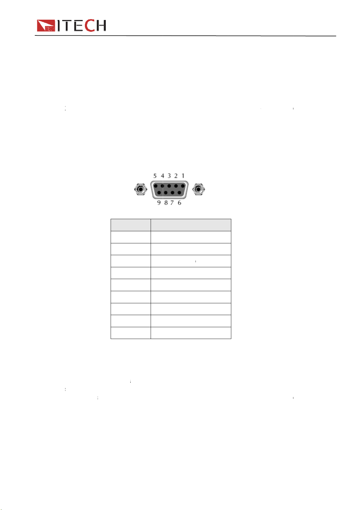
tre N
Flow co
n
c
2
e
a
o
w
t
2
e
T
pis TRs T
(
n
s
e
n
o
e
s
-
o
r
u
m
e
c
e
O
s
u
e
b
2
c
u
m
a
a
N
w
m
a
s
n
v
e
2
o
e
r
s
cTXD
c
c
S
S
c
i
v
n
d
t
e
e
s
h
R
a
n
d
n
n
o
n
o
t
m
c
s
o
d
o
e
n
n
s
c
0
O
-
o
n
n
h
t
e
s
a
e
a
,
b
o
d
s
c
RS-232
The RScomput
not use
If your c
adapter
straight
i
will do o
ecognize
lectronic l
ONE Th
trol optio
onnecti
32 serial
r) using a
null mod
mputer u
ith a DB
hrough(n
ce its inp
X_ON an
oad to sto
re’s no flo
s are stor
ns
port can
straight th
m cable.
es a DB-
25 conne
t null mod
t buffer h
d X_OFF
p outputti
w control.
d in non-
e connect
rough RS-
Table 2-
5connect
tor on on
em).
RS-232
s droppe
ent from
g charact
olatile m
d to the
232 cable
shows t
r for the
end and
connector
below ha
he control
rs until it
mory.
erial port
terminate
e pinout f
S-232int
DB-9 co
pinout
IT88
lf-full. The
ler. An X-
ees an X
f a contr
with DBr the con
rface,you
nector o
0 User
electronic
FF will c
ON.
ller (i.e., p
9 connecti
ector.
will need
the other
Manual
load
use the
rsonal
ors. Do
cable or
wired
RS-23
If you ar
Commu
trouble
having t
he comp
arity, nu
configur
he corre
S-232 co
ystem,th
he interfa
COM1, C
nication
pin n
1
2
3
4
5
6
7
8
9
shootin
ouble co
ter and th
ber of dat
d for 1 st
t interface
nnector.
internal
ce cable
M2,etc.).
etting
mbe
de
no
RX
no
GN
no
CT
RT
no
g:
municatin
e electron
bits,and
rt bit and
cables or
ote that e
iring may
ust be co
cription
onnectio
,transmit
D,receive
onnectio
D,signal g
onnectio
, clear to
, ready t
onnectio
g over the
c load mu
flow contr
1stop bit (
adapters
en if the
be incorre
nected to
data
ata
round
send
send
RS-232 i
st be confi
l options.
hese valu
ust be u
able has t
ct.
the corre
terface,c
gured for
Note that
es are fix
ed, as de
he proper
t serial po
eck the fo
he same
the eledtr
d).
cribed un
connector
rt on your
llowing:
audrate,
nic load
er
for your
omputer
User Ma
nual
42
Page 43

o
t
r
D
S
P
L
N
U
e
s
B
T T
L T
f
B
T T T T
n
t
o
u
o
n
a
t
(
e
:
:
N
D
N
r
n
r
f
O
e
e
e
e
e
B
a
s
s
r
t
a
m
a
0
o
e
(
e
b
2
s
r
s
r
n
a
a
a
a
a
n
o
s
0
t
w
w
w
,
D
o
U
h
O
o
e
n
B
w
e
r
m
c
u
、
r
p
a
r
e
G
R
C
P
e
s
G
B
e
e
1
)
o
P
e
O
C
e
a
E
r
u
e
IT88
0
o
c
d
d
d
e
S
a
u
h
▼▼
M
e
d
e
u
a
a
0 User
Manual
Before c
electroni
Baud ra
menu th
1.
2.
3.
4.
Parity=
6.2
use cabl
function
The US
The US
mmunic
c load ma
e :9600
ough pan
ata bit
top bit
arity :
EVE
OD
NO
ocal add
one
SB i
s with do
are prog
488 inter
he interfa
he interfa
OCAL_L
he interfa
orwards T
488devic
he devic
he devic
he devic
he debic
tion oper
ch that of
4800、96
l to set c
8
1
(none,ev
eight
eight
E eight
ess :
Start Bit
terfac
uble USB
ammable
ace capa
ce is 488.
ce accept
CKOUT
ce accept
RIGGER
capabiliti
understa
is SR1 c
is RL1 c
is DT1 c
tion, plea
PC.
0、1920
mmunica
n,odd)
data bits
data bits
data bits
0 ~31
8
interface t
over the
ilities of t
USB488
REN_C
equests.
MsgID =
equests t
es of the
ds all ma
pable.
pable.
pable.
e make s
、38400
ion baud
ith even
ith odd p
ithout pa
default s
ata Bits
connect
SB.
e electron
interface
NTROL,
TRIGGE
the functi
lectronic l
datory S
re that th
57600、1
ate.
arity
rity
ity
tting is 0
St
load and
ic load ar
O_TO_L
USBTM
on layer.
oad are d
PI comm
following
5200). Y
p Bit
C. All ele
describe
CAL, an
comman
scribed b
nds.
paramete
u can ent
tronic loa
below:
messag
low:
rs of
r system
and
6.3
First co
sufficien
from 0 t
“Comm
confirm.
GPIB ad
When c
commu
GPIB
ncet GPI
contact
31. Pres
nication”,
The elect
dress is s
mmunic
ication
interf
port of lo
nd tighten
+
elect GPI
onic load
ored in no
ting with
ethods a
ce
d to GPI
the scre
umber 5 t
B, and th
perates f
n-volatile
PC, you
bove.
card of
s. And th
o enter sy
n set the
om a GPI
emory.
an just s
43
C with IE
n set add
tem men
PIB addr
address
lect one
E488 BU
ess. The
, press
ss ,and
set from t
method o
. They m
ddress c
key to
se
e front p
f all the
User
st be
n be set
find
to
nel. The
anual
Page 44

t
a
h
c
c
w
C
m
o
r
t
v
a
f
t
6
p
w
c
e
r
o
c
IT88
0
C
m
a
d
0 User
Manual
Suppor
If you h
1 Check
2 Visit t
ITECH
assistan
Fast
Soft
Call ITE
User Ma
process
ve a probl
the docu
e ITECH
ustomers.
e and inc
access to
are and d
H suppo
nual
em, follow
entation
nline ser
It is the f
ludes the
email AE
river upda
t line 400
these ste
hat come
ice Web s
stest sour
ollowing f
es for the
-025-000
s:
ith the p
ite is www
e for up-t
atures:
product
44
oduct
.itechate.
-date pro
om , ITE
duct infor
H is avali
ation an
Via Acquanera, 29 22100 Como
tel. 031.526.566 (r.a.) fax 031.507.984
info@calpower.it www.calpower.it
ble to all
expert
 Loading...