

Page 1

Energy-regenerative DC
Electronic Load
Series IT8300 Programming Guide
Model: IT8311/IT8312/IT8321/IT8322/IT8331/IT8332/
IT8341/IT8342/IT8351/IT8352/IT8361/IT8362/IT8371
/IT8372/IT8381/IT8382/IT8391/IT8392
Revision: V1.0
Page 2

IT8300 Programming Guide
Statement
© Itech Electronic, Co., Ltd. 2017 No
part of this manual may be reproduced
in any form or by any means (including
electronic storage and retrieval or
translation into a foreign language)
without prior permission and written
consent from Itech Electronic, Co., Ltd.
as governed by international copyright
laws.
Manual Part Number
IT8300-402227
Revision
1st Edition: APR 17, 2017
Itech Electronic, Co., Ltd.
Trademarks
Pentium is a registered trademark of
Intel Corporation in the United States.
Microsoft, Visual Studio, Windows and
MS Windows are trademarks of
Microsoft Corporation in the United
States and/or other countries/regions.
Warranty
Materials in the document are provided
talis qualis and may be changed in
future revisions without prior notice. In
addition, within the maximum allowable
extent of laws, ITECH is not committed
to any explicit or implied guarantee for
this manual and all information therein,
including but not limited to the implied
guarantee on marketability and
availability for some special purposes.
ITECH shall not be responsible for any
error or incidental or indirect losses
caused by the provision, use or
application of this documents and
information therein. If some guarantee
clauses in other written agreements
between ITECH and users are not
consistent with clauses herein, those
clauses in other written agreements
shall prevail.
Technology Licenses
Hardware and/or software in this
document cannot be provided without a
license and can only be used or copied
according to the license.
Restricted Rights Legend
Restricted permissions of the U.S.
government. Permissions for software
and technical data which are authorized
to the U.S. Government only include
those for custom provision to end users.
ITECH follows FAR 12.211 (technical
data), 12.212 (computer software).
DFARS 252.227-7015 (technical
data--commercial products) for national
defense and DFARS 227.7202-3
(permissions for commercial computer
software or computer software
documents) while providing the
customized business licenses of
software and technical data.
Safety Notices
A CAUTION sign denotes a
hazard. It calls attention to an
operating procedure or practice
that, if not correctly performed
or adhered to, could result in
damage to the product or loss of
important data. Do not proceed
beyond a CAUTION sign until
the indicated conditions are fully
understood and met.
A WARNING sign denotes
a hazard. It calls attention to
an operating procedure or
practice that, if not correctly
performed or adhered to, could
result in personal injury or death.
Do not proceed beyond a
WARNING sign until the
indicated conditions are fully
understood and met.
NOTE
A NOTE sign denotes important
hint. It calls attention to tips or
supplementary information that
is essential for users to refer to.
Page 3
IT8300 Programming Guide
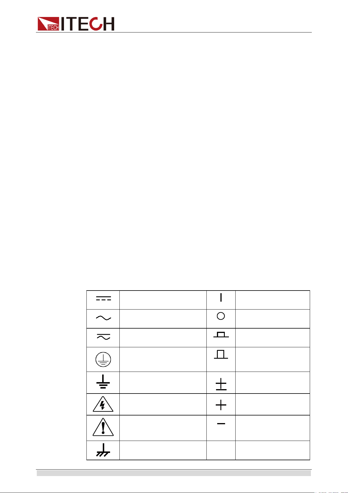
DC power
ON (with the power
switched on)
AC power
OFF (with the power
supply switched off)
Both DC and AC power supply
Power supply
switching-on status
Protective grounding terminal
Power supply
switching-off status
Grounding terminal
Reference terminal
Danger sign
Positive terminal
Warning sign (refer to specific
“Warning” or “Caution”
information in the manual)
Negative terminal
Ground wire connection end
sign
-
-
Certification and Quality Assurance
IT8300 series electronic load completely reaches nominal technical indicators
in the manual.
Warranty service
ITECH Company will provide one-year warranty services for the product
materials and manufacturing (excluding the following limitations).
When warranty service or repair is needed, please send the product to the
service unit specified by ITECH Company.
When the product is sent to ITECH Company for warranty service, the
customer must pay the one-way freight to the maintenance department of
ITECH, and ITECH will be responsible for return freight.
If the product is sent to ITECH for warranty service from other countries,
the customer will be responsible for all the freight, duties and other taxes.
Limitation of Warranty
Warranty service does not apply to the damage caused in the following
circumstances:
Damage resulting from customer-wired circuits or customer-supplied parts
or accessories;
Product which has been modified or repaired by the customer;
Damage caused by the circuit installed by the customer or damage caused
by operation of the product in non-specified environment;
The product model or serial number is altered, deleted, removed or made
illegible by customer;
Damage caused by accidents, including but not limited to lightning, water,
fire, abuse or negligence.
Safety signs
Copyright © ITECH Electronics Co., Ltd. i
Page 4

IT8300 Programming Guide
Environmental conditions
Requirement
Safety Precautions
General safety precautions below must be followed in each phase of instrument
operation. In case of failure to follow these precautions or specific warnings in
other parts of the manual, violation against the safety standards related to the
design, manufacture and purpose of the instrument will occur. If the user does
not follow these precautions, ITECH will bear no responsibility arising there
from.
Do not use the instrument if it is damaged. Before operation, check
the casing to see whether it cracks. Do not operate the instrument in
the presence of inflammable gasses, vapors or dusts.
The electronic load is provided with a power line during delivery and
should be connected to a junction box. Before operation, be sure that
the electronic load is well grounded.
Use electric wires of appropriate load. All loading wires should be
capable of bearing maximum short-circuit of electronic load without
overheating.
Check all marks on the instrument before connecting the instrument
to electronic load.
Ensure the voltage fluctuation of mains supply is less than 10% of the
working voltage range in order to reduce risks of fire and electric
shock.
Do not install alternative parts on the instrument or perform any
unauthorized modification.
Do not use the equipment when the removable cover is dismantled or
loose.
Please use the power adapter supplied by the manufacturer to avoid
accidental injury.
We do not accept responsibility for any direct or indirect financial
damage or loss of profit that might occur when using the instrument.
This instrument is used for industrial purposes, do not apply this
product to IT power supply system.
Do not use the equipment on the life support system or other
equipment with safety requirements.
Environmental conditions
Copyright © ITECH Electronics Co., Ltd. ii
If the equipment is not used in the manner specified by the
manufacturer, its protection may be damaged.
Always use dry cloth to clean the equipment housing. Do not clean
the inside of the instrument.
Do not block the air vent of the equipment.
The IT8300 series electronic load can only be used indoors or in low
condensation areas. The following table shows general environmental
requirements for this instrument.
Page 5

IT8300 Programming Guide
Operating temperature
0°C - 40°C
Operating humidity
20% - 80% (non condensing)
Storage temperature
-20°C - 70 °C
Altitude
Operating up to 2,000 meters
Installation category
Ⅱ
Pollution
Pollution degree 2
The CE tag shows that the product
complies with the provisions of all relevant
European laws (if the year is shown, it
indicates that the year when the design is
approved).
This instrument complies with the WEEE
directive (2002/96/EC) tag requirements.
This attached product tag shows that the
electrical/electronic product cannot be
discarded in household waste.
This symbol indicates that no danger will
happen or toxic substances will not leak or
cause damage in normal use within the
specified period. The service life of the product
is 10 years. The product can be used safely
within the environmental protection period;
otherwise, the product should be put into the
recycling system.
Waste electrical and electronic equipment (WEEE)
directive, 2002/96/EC
The product complies with tag requirements of the
WEEE directive (2002/96/EC). This tag indicates that the
electronic equipment cannot be disposed of as ordinary
household waste.
Product Category
According to the equipment classification in Annex I of
the WEEE directive, this instrument belongs to the
“Monitoring” product.
If you want to return the unnecessary instrument,
please contact the nearest sales office of ITECH.
Note
In order to ensure the accuracy of measurement, it is recommended to operate the
instrument half an hour after start-up.
Regulation tag
Waste electrical and electronic equipment (WEEE) directive
Copyright © ITECH Electronics Co., Ltd. iii
Page 6

IT8300 Programming Guide
IEC 61326-1:2012/ EN 61326-1:2013 ¹²³
Reference Standards
CISPR 11:2009+A1:2010/ EN 55011:2009+A1:2010 (Group 1, Class A)
IEC 61000-4-2:2008/ EN 61000-4-2:2009
IEC 61000-4-3:2006+A1:2007+A2:2010/ EN 61000-4-3:2006+A1:2008+A2:2010
IEC 61000-4-4:2004+A1:2010/ EN 61000-4-4:2004+A1:2010
IEC 61000-4-5:2005/ EN 61000-4-5:2006
IEC 61000-4-6:2008/ EN 61000-4-6:2009
IEC 61000-4-11:2004/ EN 61000-4-11:2004
Compliance Information
Complies with the essential requirements of the following applicable European
Directives, and carries the CE marking accordingly:
Electromagnetic Compatibility (EMC) Directive 2014/30/EU
Low-Voltage Directive (Safety) 2014/35/EU
Conforms with the following product standards:
EMC Standard
1. The product is intended for use in non-residential/non-domestic environments. Use of the
product in residential/domestic environments may cause electromagnetic interference.
2. Connection of the instrument to a test object may produce radiations beyond the specified
limit.
3. Use high-performance shielded interface cable to ensure conformity with the EMC standards
listed above.
Safety Standard
IEC 61010-1:2010/ EN 61010-1:2010
Copyright © ITECH Electronics Co., Ltd. iv
Page 7

IT8300 Programming Guide
Contents
Certification and Quality Assurance .......................................................................................................................... 1
Warranty service ........................................................................................................................................................ 1
Limitation of Warranty .............................................................................................................................................. 1
Safety signs ............................................................................................................................................................... 1
Safety Precautions ..................................................................................................................................................... 2
Environmental conditions .......................................................................................................................................... 2
Regulation tag............................................................................................................................................................ 3
Waste electrical and electronic equipment (WEEE) directive ................................................................................... 3
Compliance Information ............................................................................................................................................ 4
CHAPTER1 REMOTE CONTROL .................................................................................................................... 1
1.1 Overview ............................................................................................................................................................. 1
1.2 SCPI Command Introduction .............................................................................................................................. 1
1.3 Command Type of SCPI ..................................................................................................................................... 1
1.4 Message Type of SCPI ........................................................................................................................................ 3
1.5 Response Data Type ............................................................................................................................................ 4
1.6 Command Format ................................................................................................................................................ 5
1.7 Data Type ............................................................................................................................................................ 7
1.8 SCPI Command Complete .................................................................................................................................. 8
1.9 Remote Operation ................................................................................................................................................ 9
1.9.1 RS232 Interface ........................................................................................................................................... 9
1.9.2 USB Interface ............................................................................................................................................ 10
1.9.3 LAN Interface ............................................................................................................................................ 11
1.9.4 CAN Interface ............................................................................................................................................ 11
1.9.5 RS485 Interface ......................................................................................................................................... 12
1.10 Queue .............................................................................................................................................................. 12
1.11 Status byte and service request (SRQ) ............................................................................................................. 13
1.12 Serial poll and SRQ ......................................................................................................................................... 14
1.13 Trigger Model (GPIB Operation) .................................................................................................................... 14
CHAPTER2 SCPI REGISTER .......................................................................................................................... 16
2.1 Status Register ................................................................................................................................................... 16
2.2 Condition register .............................................................................................................................................. 18
2.3 Event register ................................ ................................ ................................ ..................................................... 18
2.4 Enable register ................................................................................................................................................... 19
CHAPTER3 ESSENTIAL COMMANDS ......................................................................................................... 20
STATus:QUEStionable[:EVENt]? .......................................................................................................................... 20
STATus:QUEStionable:ENABle ............................................................................................................................ 20
STATus:QUEStionable:PTRansition ...................................................................................................................... 21
STATus:QUEStionable:NTRansition ..................................................................................................................... 21
STATus:QUEStionable:CONDition? ...................................................................................................................... 22
STATus:OPERation[:EVENt]? ............................................................................................................................... 22
STATus:OPERation:ENABle ................................................................................................................................. 23
STATus:OPERation:CONDition? ........................................................................................................................... 23
STATus:PRESet ...................................................................................................................................................... 24
CHAPTER4 SYSTEM COMMANDS ............................................................................................................... 25
SYSTem:POSetup ................................................................................................................................................... 25
SYSTem:VERSion? ................................................................................................................................................ 25
SYSTem:ERRor? .................................................................................................................................................... 26
SYSTem:CLEar....................................................................................................................................................... 26
SYSTem:LOCal ...................................................................................................................................................... 26
SYSTem:REMote ................................ ................................ ................................ .................................................... 27
SYSTem:RWLock ................................................................................................................................................... 27
SYSTem:BEEPer:IMMediate ................................................................................................................................. 28
SYSTem:BEEPer[:STATe] ..................................................................................................................................... 28
SYSTem:KEY ................................................................................................................................ ......................... 28
SYSTem:COMMunicate:SELect ............................................................................................................................ 29
SYSTem:COMMunicate:RS232:BAUDrate ........................................................................................................... 29
SYSTem:COMMunicate:RS485:BAUDrate ........................................................................................................... 29
SYSTem:COMMunicate:LAN:CURRent:ADDRess .............................................................................................. 30
Copyright © ITECH Electronics Co., Ltd. v
Page 8

IT8300 Programming Guide
SYSTem:COMMunicate:LAN:CURRent:DGATeway........................................................................................... 30
SYSTem:COMMunicate:LAN:CURRent:SMASk ................................................................................................. 31
SYSTem:COMMunicate:LAN:SOCKetport ........................................................................................................... 31
SYSTem:COMMunicate:LAN:MACaddress? ........................................................................................................ 32
CHAPTER5 MEASURE COMMANDS ................................ ................................ ............................................ 33
FETCh:VOLTage[:DC]? ......................................................................................................................................... 33
MEASure:VOLTage[:DC]? .................................................................................................................................... 33
FETCh:VOLTage:MAX? ........................................................................................................................................ 33
MEASure:VOLTage:MAX? ................................................................................................................................... 33
FETCh:VOLTage:MIN? ......................................................................................................................................... 34
MEASure:VOLTage:MIN? ..................................................................................................................................... 34
FETCh:CURRent[:DC]? ......................................................................................................................................... 34
MEASure:CURRent[:DC]? ..................................................................................................................................... 34
FETCh:CURRent:MAX? ........................................................................................................................................ 34
MEASure:CURRent:MAX? .................................................................................................................................... 34
FETCh:CURRent:MIN? .......................................................................................................................................... 35
MEASure:CURRent:MIN? ..................................................................................................................................... 35
FETCh:POWer[:DC]? ............................................................................................................................................. 35
FETCh:CAPability? ................................................................................................................................................ 36
MEASure:CAPability? ............................................................................................................................................ 36
FETCh:TIME?......................................................................................................................................................... 36
MEASure:TIME? .................................................................................................................................................... 36
FETCh:ACMeter:EACStage? ................................................................................................................................. 36
FETCh:ACMeter:EACTotal? .................................................................................................................................. 37
CHAPTER6 TRIGGER SUBSYSTEM ............................................................................................................. 38
TRIGger[:IMMediate] ............................................................................................................................................. 38
TRIGger:SOURce ................................................................................................................................................... 38
TRIGger:TIMer ....................................................................................................................................................... 39
CHAPTER7 TRACE SUBSYSTEM .................................................................................................................. 40
TRACe:CLEar ......................................................................................................................................................... 40
TRACe:FREE? ........................................................................................................................................................ 40
TRACe:POINts ....................................................................................................................................................... 40
TRACe:FEED ......................................................................................................................................................... 41
TRACe:FEED:CONTrol ......................................................................................................................................... 41
TRACe:DATA?....................................................................................................................................................... 42
TRACe:FILTer[:STATe] ........................................................................................................................................ 42
TRACe:DELay ........................................................................................................................................................ 43
TRACe:TIMer ................................................................ ................................................................ ......................... 43
CHAPTER8 SOURCE SUBSYSTEM ............................................................................................................... 45
[SOURce:]INPut[:STATe] ...................................................................................................................................... 45
[SOURce:]INPut:SHORt[:STATe] ......................................................................................................................... 45
[SOURce:]INPut:TIMer[:STATe]........................................................................................................................... 46
[SOURce:]INPut:TIMer:DELay ............................................................................................................................. 46
[SOURce:]REMote:SENSe[:STATe] ..................................................................................................................... 47
[SOURce:]FUNCtion .............................................................................................................................................. 47
[SOURce:]FUNCtion:MODE ................................................................................................................................. 48
[SOURce:]TRANsient[:STATe] ............................................................................................................................. 49
[SOURce:]PROTection:CLEar ............................................................................................................................... 49
[SOURce:]CURRent[:LEVel][:IMMediate] ........................................................................................................... 49
[SOURce:]CURRent:RANGe ................................................................................................................................. 50
[SOURce:]CURRent:SLEW[:BOTH] ..................................................................................................................... 51
[SOURce:]CURRent:SLEW:POSitive .................................................................................................................... 51
[SOURce:]CURRent:SLEW:NEGative .................................................................................................................. 52
[SOURce:]CURRent:SLEWrate:STATe ................................................................................................................. 53
[SOURce:]CURRent:PROTection:STATe.............................................................................................................. 53
[SOURce:]CURRent:PROTection[:LEVel] ............................................................................................................ 54
[SOURce:]CURRent:PROTection:DELay .............................................................................................................. 54
[SOURce:]CURRent:TRANsient:MODE ............................................................................................................... 55
[SOURce:]CURRent:TRANsient:ALEVel ............................................................................................................. 56
Copyright © ITECH Electronics Co., Ltd. vi
Page 9

IT8300 Programming Guide
[SOURce:]CURRent:TRANsient:BLEVel.............................................................................................................. 56
[SOURce:]CURRent:TRANsient:AWIDth ............................................................................................................. 57
[SOURce:]CURRent:TRANsient:BWIDth ............................................................................................................. 57
[SOURce:]CURRent:HIGH .................................................................................................................................... 57
[SOURce:]CURRent:LOW ..................................................................................................................................... 57
[SOURce:]VOLTage[:LEVel][:IMMediate] ........................................................................................................... 58
[SOURce:]VOLTage:RANGe ................................................................................................................................. 58
[SOURce:]VOLTage[:LEVel]:ON .......................................................................................................................... 59
[SOURce:]VOLTage:LATCh[:STATe] .................................................................................................................. 60
[SOURce:]VOLTage:HIGH .................................................................................................................................... 60
[SOURce:]VOLTage:LOW ..................................................................................................................................... 60
[SOURce:]VOLTage[:LEVel]:ON:HYSTeresis .................................................................................................. 61
[SOURce:]RESistance[:LEVel][:IMMediate] ......................................................................................................... 61
[SOURce:]RESistance:RANGe............................................................................................................................... 62
[SOURce:]RESistance:HIGH .................................................................................................................................. 63
[SOURce:]RESistance:LOW .................................................................................................................................. 63
[SOURce:]POWer[:LEVel][:IMMediate] ............................................................................................................... 63
[SOURce:]POWer:RANGe ..................................................................................................................................... 64
[SOURce:]POWer:HIGH ........................................................................................................................................ 64
[SOURce:]POWer:LOW ......................................................................................................................................... 64
[SOURce:]POWer:PROTection[:LEVel] ................................................................................................................ 65
[SOURce:]POWer:PROTection:DELay.................................................................................................................. 66
[SOURce:]POWer:CONFig[:LEVel] ...................................................................................................................... 66
[SOURce:]INPut:CONTrol <EXTernal/INTernal> ................................................................................................ 67
[SOURce:]ACMeter:EACStage:CLEar .................................................................................................................. 67
CHAPTER9 LIST COMMANDS ....................................................................................................................... 68
[SOURce:]LIST:RANGe ........................................................................................................................................ 68
[SOURce:]LIST:COUNt ......................................................................................................................................... 68
[SOURce:]LIST:STEP ............................................................................................................................................ 69
[SOURce:]LIST:SLOWrate[:STATe] <LOW|HIGH> ............................................................................................ 69
[SOURce:]LIST:LEVel? ......................................................................................................................................... 70
[SOURce:]LIST:SLEW[:BOTH] ............................................................................................................................ 70
[SOURce:]LIST:WIDth .......................................................................................................................................... 71
[SOURce:]LIST:SAV ............................................................................................................................................. 71
[SOURce:]LIST:RCL .............................................................................................................................................. 72
CHAPTER10 CALIBRATION COMMANDS ................................................................................................... 73
CALibrate:SECure[:STATe] ................................................................................................................................... 73
CALibrate:INITial ................................................................................................................................................... 73
CALibrate:SAVe ..................................................................................................................................................... 74
CALibrate:CURRent:POINt ................................................................................................ .................................... 74
CALibrate:CURRent[:LEVel] ................................................................................................................................. 75
CALibrate:CURRent:METEr:POINt ...................................................................................................................... 75
CALibrate:CURRent:METEr[:LEVel] ................................................................................................................... 75
CALibrate:VOLTage:POINt ................................................................................................................................... 76
CALibrate:VOLTage[:LEVel] ................................................................................................................................ 76
CALibrate:VOLTage:METEr:POINt ...................................................................................................................... 77
CALibrate:VOLTage:METEr[:LEVel] ................................................................................................................... 77
CALibration:STRing ............................................................................................................................................... 78
CALibration:STRing? ............................................................................................................................................. 78
CHAPTER11 IEEE488.2 COMMANDS ............................................................................................................. 79
*CLS - Clear Status ................................................................................................................................................. 80
*ESE <NRf> - Event Enable ................................................................................................................................... 80
*ESR? ...................................................................................................................................................................... 81
*IDN? ...................................................................................................................................................................... 81
*OPC ....................................................................................................................................................................... 81
*PSC ................................................................................................................................ ................................ ........ 82
*RCL ....................................................................................................................................................................... 83
*RST ....................................................................................................................................................................... 83
*SAV ....................................................................................................................................................................... 83
*SRE ....................................................................................................................................................................... 84
Copyright © ITECH Electronics Co., Ltd. vii
Page 10

IT8300 Programming Guide
*STB? ...................................................................................................................................................................... 84
*TRG ....................................................................................................................................................................... 85
*TST? ...................................................................................................................................................................... 85
*WAI ....................................................................................................................................................................... 85
CHAPTER12 ERROR INFORMATION ................................................................ ............................................ 87
Copyright © ITECH Electronics Co., Ltd. viii
Page 11

Remote Control
Chapter1 Remote Control
1.1 Overview
This chapter will provide following remote configuration introductions:
SCPI Command Introduction
Command type
Command format
Data format
Remote operation
1.2 SCPI Command Introduction
Standard Command for Programmable Instrumentation (SCPI) is a
programming language for controlling instrument functions via GPIB, RS-232,
USB, and Ethernet interfaces. SCPI is placed on the top of the IEEE 488.2
hardware section. The same SCPI commands and parameters control the
same function of different machines.
1.3 Command Type of SCPI
SCPI has two types of commands, common and subsystem.
Common commands generally are not related to specific operation but to
controlling overallelectronic load functions, such as reset, status, and
synchronization. All commoncommands consist of a three-letter mnemonic
preceded by an asterisk: *RST *IDN? *SRE 8.
Subsystem commands perform specific electronic load functions. They are
organized into an inverted tree structure with the "root" at the top. The
following figure shows a portion of a subsyste command tree, from which
you access the commands located along the various paths.
Multiple commands in a message
Multiple SCPI commands can be combined and sent as a single
message with one message terminator. There are two important
considerations when sending several commands within a single
message:
Use a semicolon to separate commands within a message.
Head paths influence how the instrument interprets commands.
We consider the head path as a string which will be inserted in front of
Copyright © ITECH Electronics Co., Ltd. 1
Page 12

Remote Control
every command of a message. As for the first command of a message,
the head path is a null string; for each subsequent command, the head
path is a string which is defined to form the current command until and
including the head of the last colon separator. A message with two
combined commands: CURR:LEV 3;PROT:STAT OFF
The example indicates the effect of semicolon and explains the concept
of head path. Since the head path is defined to be "CURR" after "curr: lev
3", the head of the second command, "curr", is deleted and the
instrument explains the second command as: CURR:PROT:STAT OFF
If "curr" is explicitly included in the second command, it is semantically
wrong. Since combining it with the head path will become
"CURR:CURR:PROT:STAT OFF", resulting in wrong command.
Movement in the subsystem
In order to combine commands from different subsystems, you need to
be able to reset the header path to a null string within a message. You do
this by beginning the command with a colon (:), which discards any
previous header path. For example, you could clear the output protection
and check the status of the Operation Condition register in one message
by using a root specifier as follows:
PROTection:CLEAr;:STATus:OPERation:CONDition?
The following message shows how to combine commands from different
subsystems as well as within the same subsystem:
POWer:LEVel 200;PROTection 28; :CURRent:LEVel 3;PROTection:STATe ON
Note the use of the optional header LEVel to maintain the correct path
within the voltage and current subsystems, and the use of the root
specifier to move between subsystems.
Including Common Commands
You can combine common commands with subsystem commands in the
same message. Treat the common command as a message unit by
separating it with a semicolon (the message unit separator). Common
commands do not affect the header path; you may insert them anywhere
in the message.
VOLTage:TRIGgered 17.5;:INITialize;*TRG
OUTPut OFF;*RCL 2;OUTPut ONIT872X-3X SCPI Communication protocol 17
Case sensitivity
Common commands and SCPI commands are not case sensitive. You
can use upper or lower, for example:
*RST = *rst
:DATA? = :data?
:SYSTem:PRESet = :system:preset
Long-form and short-form versions
A SCPI command word can be sent in its long-form or short-form version.
The command subsystem tables in Section 5 provide the in the
long-form version. However, the short-form version is indicated by upper
case characters. Examples:
Copyright © ITECH Electronics Co., Ltd. 2
Page 13

Remote Control
:SYSTem:PRESet long-form
:SYST:PRES short form
:SYSTem:PRES long-form and short-form combination
Note that each command word must be in long-form or short-form, and
not something in between.
For example, :SYSTe:PRESe is illegal and will generate an error. The
command will not be executed.
Query
Observe the following precautions with queries:
Set up the proper number of variables for the returned data. For example, if
you are reading back a measurement array, you must dimension the array
according to the number of measurements that you have placed in the
measurement buffer.
Read back all the results of a query before sending another command to
the electronic load. Otherwise a Query Interrupted error will occur and the
unreturned data will be lost.
1.4 Message Type of SCPI
There are two types of SCPI messages, program and response.
Program message: A program message consists of one or more properly
formatted SCPI commands sent from the controller to the electronic load.
The message, which may be sent at any time, requests the electronic load
to perform some action.
Response message: A response message consists of data in a specific
SCPI format sent from the electronic load to the controller. The electronic
load sends the message only when commanded by a program message
called a "query."
The next figure illustrates SCPI message structure:
The Message Unit
The simplest SCPI command is a single message unit consisting of a command
header (or keyword) followed by a message terminator. The message unit may
include a parameter after the header. The parameter can be numeric or a
string.
VOLTage 20<NL>
Copyright © ITECH Electronics Co., Ltd. 3
Page 14

Remote Control
<CRD> Character Response Data. Permits the return of character strings.
<AARD> Arbitrary ASCII Response Data. Permits the return of undelimited 7-bit
ASCII. This data type has an implied message terminator.
<SRD> String Response Data. Returns string parameters enclosed in double quotes
Headers
Headers, also referred to as keywords, are instructions recognized by the
electronic load. Headers may be either in the long form or the short form. In the
long form, the header is completely spelled out, such as VOLTAGE, STATUS,
and DELAY. In the short form, the header has only the first three or four letters,
such as VOLT, STAT, and DEL.
Query Indicator
Following a header with a question mark turns it into a query (VOLTage?,
VOLTage:PROTection?). If a query contains a parameter, place the query
indicator at the end of the last header(VOLTage:PROTection?MAX).
Message Unit Separator
When two or more message units are combined into a compound message,
separate the units with a semicolon (STATus:OPERation?;QUEStionable?).
Root Specifier
When it precedes the first header of a message unit, the colon becomes the
root specifier. It tells the command parser that this is the root or the top node of
the command tree.
Message Terminator
A terminator informs SCPI that it has reached the end of a message. Three
permitted message terminators are:
newline (<NL>),decimal 10 or hexadecimal 0X0A in ASCII.
end or identify (<END>)
both of the above (<NL><END>).
In the examples of this guide, there is an assumed message terminator at the
end of each message.
Command execution rules
Commands execute in the order that they are presented in the program
message.
An invalid command generates an error and, of course, is not executed.
Valid commands that precede an invalid command in a multiple command
program message are executed.
Valid commands that follow an invalid command in a multiple command
program message are ignored.
1.5 Response Data Type
Character strings returned by query statements may take either of the following
forms, depending on the length of the returned string:
Copyright © ITECH Electronics Co., Ltd. 4
Page 15

Remote Control
Response messages
A response message is the message sent by the instrument to the computer in
response to aquery command.
Sending a response message
Afte sending a query command, the response message is placed in the Output
Queue. When the IT8300 series is then addressed to talk, the response
message is sent from the Output Queue to the computer.
Multiple response messages
If you send more than one query command in the same program message (see
the paragraph entitled, “ Multiple Command Messages “), the multiple response
messages for all the queries is sent to the computer when the IT8300 series is
addressed to talk. The responses are sent in the order that the query
commands were sent and are separated by semicolons (;). Items within the
same query are separated by commas (,). The following example shows the
response message for a program message that contains four single item query
commands:
0; 1; 1; 0
Response message terminator (RMT)
Each response is terminated with an LF (line feed) and EOI (end or identify).
The following example shows how a multiple response message is terminated:
0; 1; 1; 0; <RMT>
Message exchange protocol
Two rules summarize the message exchange protocol:
Rule 1.You must always tell the IT8300 series what to send to the computer.
The following two steps must always be performed to send information from the
instrument other computer:
1. Send the appropriate query command(s) in a program message.1.
2. Address the IT8300 series to talk.
Rule 2.The complete response message must be received by the computer
before another program message can be sent to the IT8300 series.
1.6 Command Format
Formats for command display are as follows:
[SOURce[1|2]:]VOLTage:UNIT {VPP|VRMS|DBM}
[SOURce[1|2]:]FREQuency:CENTer
{<frequency>|MINimum|MAXimum|DEFault}
Based on the command syntax, most commands (and certain Parameter) are
expressed in both upper and lower cases. Upper case refers to abbreviation of
commands. Shorter program line may send commands in abbreviated format.
Long-format commands may be sent to ensure better program readability.
For example, both formats of VOLT and VOLTAGE are acceptable in the above
syntax statements. Upper or lower case may be used. Therefore, formats of
VOLTAGE, volt and Volt are all acceptable. Other formats (such as VOL and
VOLTAG) are invalid and will cause errors.
Parameter options with given command strings are included in the brace
({ }). The brace is not sent along with command strings.
Copyright © ITECH Electronics Co., Ltd. 5
Page 16

Remote Control
Vertical stripes (|) separate several parameter options with given command
strings. For example, {VPP|VRMS|DBM} indicates that you may assign
"APP", "VRMS" or "DBM" in the above commands. Vertical stripes are not
sent along with command strings.
Angle brackets (< >) in the second example indicates that a value must be
assigned to the parameter in the brace. For example, the parameter in the
angle bracket is <frequency> in the above syntax statements. Angle
brackets are not sent along with command strings. You must assign a value
(such as "FREQ:CENT 1000") to the parameter, unless you select other
options displayed in the syntax (such as "FREQ:CENT MIN").
Some syntax elements (such as nodes and Parameter) are included in
square brackets ([ ]). It indicates that these elements can be selected and
omitted. Angle brackets are not sent along with command strings. If no
value is assigned to the optional Parameter, the instrument will select a
default value. In the above examples, "SOURce[1|2]" indicates that you
may refer to source channel 1 by "SOURce" or "SOURce1" or "SOUR1" or
"SOUR". In addition, since the whole SOURce node is optional (in the
square bracket), you can refer to the channel 1 by omitting the whole
SOURce node. It is because the channel 1 is the default channel for
SOURce language node. On the other hand, if you want to refer to channel
2, "SOURce2" or "SOUR2" must be used in the program line.
Colon (:)
It is used to separate key words of a command with the key words in next level.
As shown below:
APPL:SIN 455E3,1.15,0.0
In this example, APPLy command assigns a sine wave with frequency of 455
KHz, amplitude of 1.15 V and DC offset of 0.0 V.
Semicolon (;)
It is used to separate several commands in the same subsystem and can also
minimize typing. For example, to send the following command string:
TRIG:SOUR EXT; COUNT 10
has the same effect as sending the following two commands:
TRIG:SOUR EXT
TRIG:COUNT 10
Question mark (?)
You can insert question marks into a command to query current values of most
Parameter. For example, the following commands will trigger to set the count as
10:
TRIG:COUN 10
Then, you may query count value by sending the following command:
TRIG:COUN?
You may also query the allowable minimum or maximum count as follows:
TRIG:COUN?MIN
TRIG:COUN?MAX
Comma (,)
If a command requires several Parameter, then a comma must be used to
separate adjacent Parameter.
Copyright © ITECH Electronics Co., Ltd. 6
Page 17

Remote Control
Space
You must use blank characters, [TAB] or [Space] to separate Parameter with
key words of commands.
Generic commands (*)
Execute functions like reset, self inspection and status operation. Generic
commands always start with a asterisk (*) and occupy 3 character sizes,
including one or more Parameter. Key words of a command and the first
parameter are separated by a space. Semicolon (;) can separate several
commands as follows:
*RST; *CLS; *ESE 32; *OPC?
Command terminator
Command strings sent to the instrument must end with a <Newline> (<NL>)
character. IEEE-488 EOI (End or Identify) information can be used as <NL>
character to replace termination command string of <NL> character. It is
acceptable to place one <NL> after a <Enter>. Termination of command string
always resets current SCPI command path to root level.
NOTE
As for every SCPI message with one query sent to the instrument, the
instrument will use a <NL> or newline sign (EOI) to terminate
response of return. For example, if "DISP:TEXT?" is sent, <NL> will
be placed after the returned data string to terminate response. If an
SCPI message includes several queries separated by semicolon
(such as "DISP?;DISP:TEXT?"), <NL> will terminate response
returned after response to the last query. In all cases, the program
must read <NL> in response before another command is sent to the
instrument, otherwise errors will be caused.
1.7 Data Type
SCPI language defines several data types used for program message and
response messages.
Numerical parameter
Commands requiring numerical Parameter support the notations of all common
decimal notations, including optional signs, decimal points, scientific notation,
etc. Special values of numerical Parameter are also acceptable, such as MIN,
MAX and DEF. In addition, suffixes for engineering units can also be sent
together with numerical Parameter (including M, k, m or u). If the command
accepts only some specific values, the instrument will automatically round the
input Parameter to acceptable values. The following commands require
numerical Parameter of frequency value:
[SOURce[1|2]:]FREQuency:CENTer {<Frequency>|MINimum|MAXimum}
<NR1>: There is an implicit decimal point in the last bit,such as 273
<NR2>: There is an explicit decimal point,such as .273
<NR3>: There are an explicit decimal point and exponential,such as
2.73E+22.73E+2
<Nrf>:The extensible form includes <NR1>, <NR2> and <NR3>,such
as 273 273. 2.73E2273 273. 2.73E2
<Nrf+>: The extensible decimal form includes <NRf> and MIN MAX
DEF, such as 273 273. 2.73E2 MAX. MIN and MAX are the minimum
and maximum finite number. Within the range of the parameter
Copyright © ITECH Electronics Co., Ltd. 7
Page 18

Remote Control
definition, DEF is the default of the parameter.
Discrete parameter
Discrete Parameter are used for settings with limited number of programming
values (such as IMMediate, EXTernal or BUS). They can use short and long
format like key words of commands. They may be expressed in both upper and
lower case. The query response always returns uppercase Parameter in short
format. The following commands require discrete Parameter in voltage unit:
[SOURce[1|2]:]VOLTage:UNIT {VPP|VRMS|DBM}
Boolean parameter
Boolean Parameter refer to true or false binary conditions. In case of false
conditions, the instrument will accept "OFF" or "0". In case of true conditions,
the instrument will accept "ON" or "1". In query of Boolean settings, the
instrument will always return "0" or "1". Boolean Parameter are required by the
following commands:
DISPlay {OFF|0|ON|1}
ASCII string Parameter
String Parameter may actually include all ASCII character sets. Character
strings must start and end with paired quotation marks; and single quotation
marks or double quotation marks are both allowed. Quotation mark separators
may also act as one part of a string, they can be typed twice without any
character added between them. String parameter is used in the following
command:
DISPlay:TEXT <quoted string>
For example, the following commands display message of "WAITING..."
(without quotation marks) on the front panel of the instrument.
DISP:TEXT "WAITING..."
Single quotation marks may also be used to display the same message.
DISP:TEXT 'WAITING...'
1.8 SCPI Command Complete
SCPI commands sent to the electronic load are processed either sequentially
or in parallel. Sequential commands finish execution before a subsequent
command begins. Parallel commands allow other commands to begin
executing while the parallel command is still executing. Commands that affect
trigger actions are among the parallel commands.
*WAI, *OPC, and *OPC:Common commands provide different ways of
indicating when all transmitted commands, including any parallel ones, have
completed their operations. Some practical considerations for using these
commands are as follows:
*WAI: This prevents the electronic load from processing subsequent
commands until all pending operations are completed.
*OPC?: This places a 1 in the Output Queue when all pending operations have
completed. Because it requires your program to read the returned value before
executing the next program statement, *OPC? can be used to cause the
controller to wait for commands to complete before proceeding with its
program.
*OPC: This sets the OPC status bit when all pending operations have
completed. Since your program can read this status bit on an interrupt basis,
*OPC allows subsequent commands to be executed.
Note
The trigger system must be in the Idle state in order for the status OPC bit to be true.
Copyright © ITECH Electronics Co., Ltd. 8
Page 19

Remote Control
Therefore, as far as triggers are concerned, OPC is false whenever the trigger
system is in the Initiated state.
Using Device Clear
You can send a device clear at any time to abort a SCPI command that may be
hanging up the GPIB interface. The status registers, the error queue, and all
configuration states are left unchanged when a device clear message is
received. Device clear performs the following actions:
The input and output buffers of the electronic load are cleared.
The electronic load is prepared to accept a new command string.
The following statement shows how to send a device clear over the GPIB
interface using GW BASIC:
CLEAR 705 IEEE-488 Device Clear
The following statement shows how to send a device clear over the GPIB
interface using the GPIB command library for C or QuickBASIC.
IOCLEAR (705)
1.9 Remote Operation
IT8300 series have five standard communication interfaces: RS232, USB,
RS485, LAN and CAN. The customer can choose any one according to his
demands.
1.9.1 RS232 Interface
Cable connection load with both ends of COM interface (DB9) and computer.
Composite key [Shift] + 8(System) on front board can be used to enter system
menu for activation.
In RS-232 interface, all SCPI commands can be used for programming. If
RS-232 interface is selected, in accordance with internal connection of data
terminal equipment (DTE) and data communication equipment (DCE) as
defined in EIA RS-232, the load is connected to another DTE (e.g., PC COM
interface) with direct-connected Modem cable.
Note
The setup of RS232 in the program must be consistent with the system setup of the instrument.
Press [Shift] + 8(System) to modify the setup of the instrument if they don’t match.
RS-232 data format
RS-232 data comprises start bit, odd and even parity check bit, stop bit and
8-bit data bit. Start bit and stop bit are not editable. However, next odd or even
item can be selected by front board [Shift] + 8(System). The odd and even
items are saved in NVM.
Baud rate
Through front board [Shift] + 8(System), the user may select one Baud rate
saved in NVM: 4800 /9600 /19200 /38400 /57600 /115200
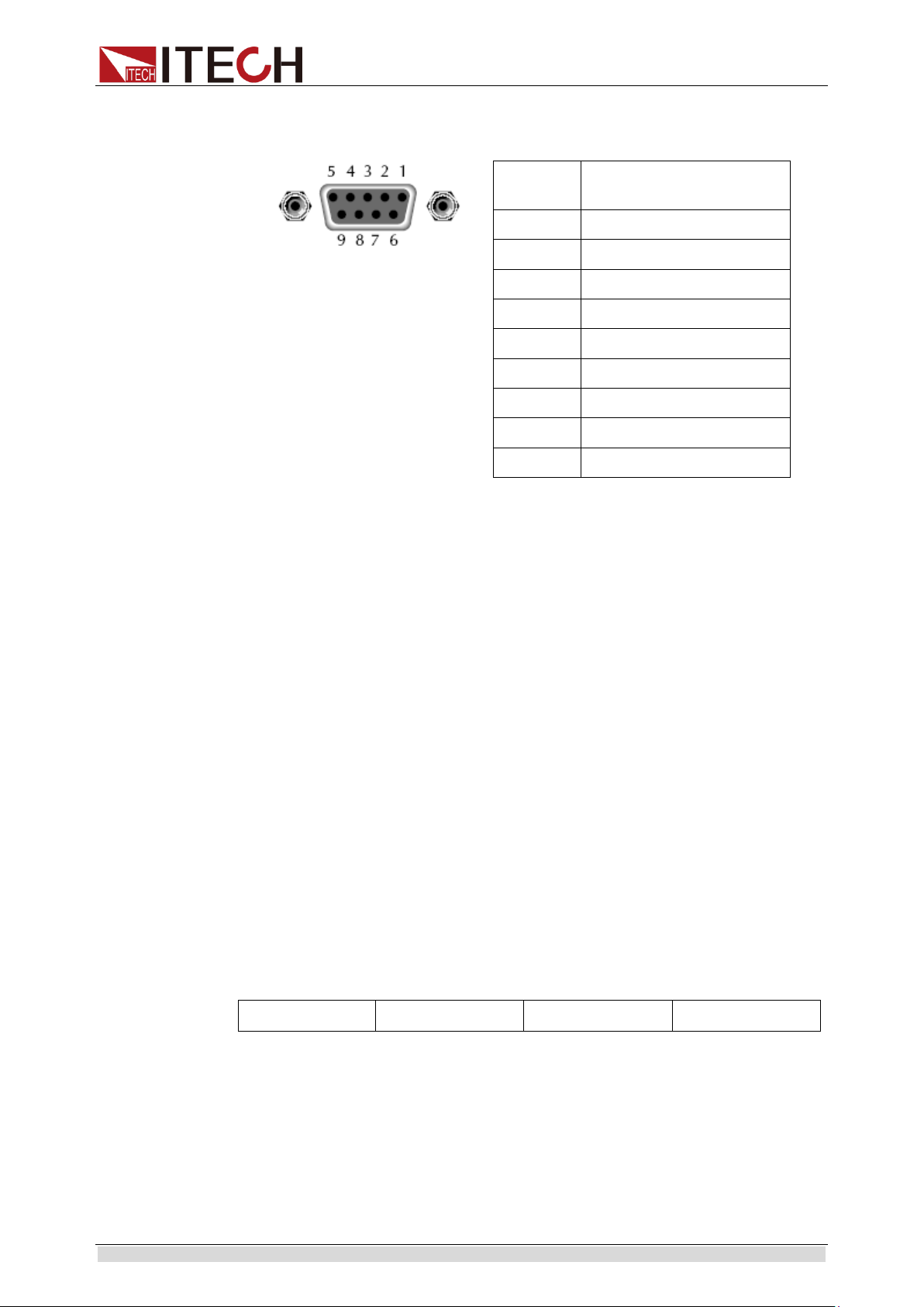
RS-232 Connection
Use RS-232 cable with DB-9 interface because the RS-232 serial port can be
connected controller (e.g. PC) serial port. Do not use modulating cable of
air-conditioner. Refer to Table 2-2 for plug pin.
If your computer is provided with a RS-232 interface with DB-25 plug, a cable
and a adapter with DB-25 plug (one end) and DB-9 plug (the other end) are
Copyright © ITECH Electronics Co., Ltd. 9
Page 20
Remote Control
RS232 Pins of Plug
Base pin
number
Description
1
No conjunction
2
TXD, data transmission
3
RXD, data receiving
4
No conjunction
5
GND, grounding
6
No conjunction
7
CTS, clear to send
8
RTS, request to send
9
No conjunction
Start Bit
Parity=None
8 Data Bits
Stop Bit
required (not the modulating cable of the air-conditioner).
RS-232 troubleshooting:
In case of connection failure of RS-232, perform following check:
Check if the computer and load are provided with same Baud rate, parity
check bit, data bit and flow control. The power shall be configured with one
start bit (fixed) and one stop bit (fixed).
Just as described in the RS-232 connector, correct interface cable or
adapter shall be adopted. Note: even if the cable is equipped with right plug,
internal wiring may be incorrect.
The interface cable must be connected to the correct serial port (COM1,
COM2, etc.) of the computer.
Setting of communication
Before communication operation, be sure to match load and PC parameters (as
follows).
Baud rate: 9600 (4800/9600/19200/38400/57600/15200). You may enter
system menu through the board to set communication Baud rate.
Data bit: 8 bits
Stop bit: 1 bit
Check: (none, even, odd)
EVEN 8 data bits have even-parity check
ODD 8 data bits have odd-parity check
NONE 8 data bits have no check
Local address: (0-31, factory set value: 0)
1.9.2 USB Interface
Copyright © ITECH Electronics Co., Ltd. 10
Connect the load and the computer using a cable with two USB interfaces
(each end). All functions of the load can be programmed via USB.
The functions of load USB488 interface are as follows:
The interface is 488.2 USB488 Interface.
The interface receives requests of REN_CONTROL, GO_TO_LOCAL and
LOCAL_LOCKOUT.
Page 21
Remote Control
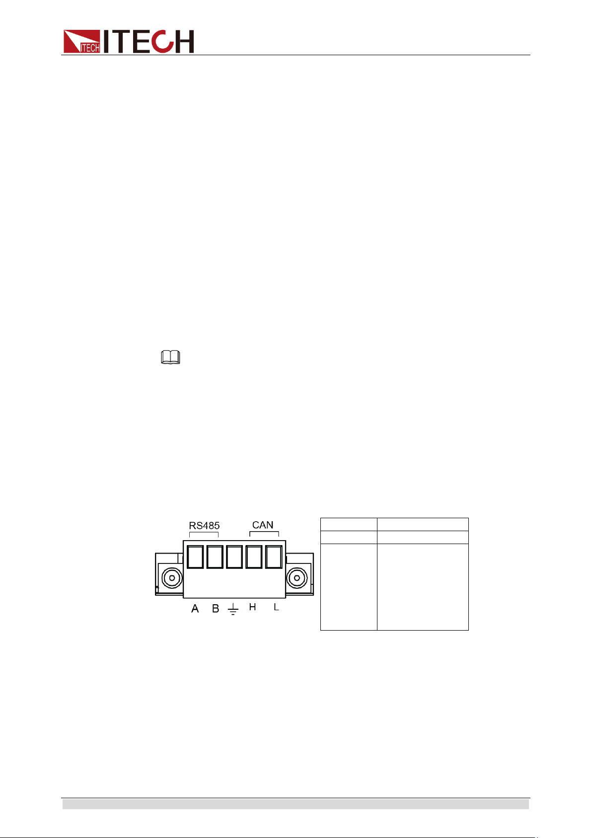
CAN INTERFACE PIN
PIN
DESCRIPTION
H
CAN_H
L
CAN_L
The interface receives the command MsgID=TRIGGER USBTMC and
conveys the TRIGGER command to the functional layer.
The functions of load USB488 device are as follows:
Capable to read all common SCPI commands.
SR1 enabled.
RL1 enabled.
DT1 enabled.
1.9.3 LAN Interface
Press [Shift] + 8(System) button to enter the system set. Please select “LAN”
in the Communication from System and then configure Gateway, IP, Mask and
Socket Port in the LAN option.
Connect the LAN interface of load to the computer with a reticle (crossed). The
gateway address should be consistent with that of the PC, and the IP address
should be at the same network segment with the PC’s IP address.
1.9.4 CAN Interface
There is one CAN interface at the rear panel. The user can use this terminal for
PC connection; to activate connection, be sure that the values set in the
System menu are same as the corresponding values set in PC.
Baud Rate
In the front panel [Shift] + 8(System), under the System menu, the user can
select one Baud rate stored in NVM:
20K|40K|50k|80k|100k|125k|150K|200k|250k|400K|500K|1000K
CAN Pin Definition
CAN interface pin is as follows.
Note
CAN setting in the program shall be consistent with the one set in the System menu of front
panel. To query and change, press the composite key [Shift] + 8(System) to enter the
setting screen in System menu for query and change. For details, refer to 3.6 System Menu.
CAN Troubleshooting:
Copyright © ITECH Electronics Co., Ltd. 11
If CAN connection fails, check that:
1. The PC and load have same Baud rate.
2. Appropriate interface pin or adapter is used, as described in CAN
connector.
3. The interface cable is correctly connected (CAN_H to CAN_H, CAN_L to
CAN_L).
Check whether 120 Ω terminal resistance is connected.
Page 22
Remote Control
BAUD RATE
(PRESCALE)
PTS
PBS
20K
150
10
1
40K
75
10
1
50K
60
10
1
80K
75 4 0
100K
30
10
1
125K
24
10
1
150K
20
10
1
200K
15
10
1
250K
12
10
1
400K
15 4 0
500K
6
10 1 1000K
3
10
1
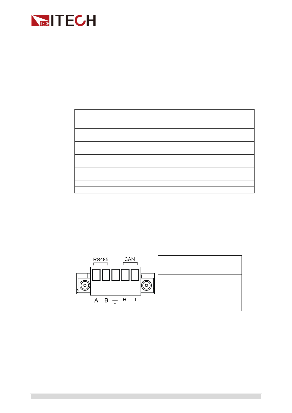
RS485 INTERFACE PIN
PIN
DESCRIPTION
A
A cable of RS485
interface
B
B cable of RS485
interface
Setting Communication
Before running communication, please match the load parameters with the PC
parameters as shown below.
Baud rate: 20K(40K, 50K, 80K, 100K, 125K, 150K, 200K, 250K, 400K, 500K,
1000K). You can enter the System menu through panel and set the
communication Baud rate
Addr.: 1-99
Prescale (Pres): Not settable. Change with Baud rate setting.
PTS (BS1): Not settable. Change with Baud rate setting.
PBS (BS2): Not settable. Change with Baud rate setting.
1.9.5 RS485 Interface
There is one RS485 interface at the rear panel. The user can use this terminal
for PC connection; to activate connection, be sure that the values set in the
System menu are same as the corresponding values set in PC.
Through front board [Shift] + 8(System), the user can set the Baud rate, Data
bit, Stop bit and check. And the operation method is same as RS232.
RS485 interface pin is as follows.
1.10 Queue
Copyright © ITECH Electronics Co., Ltd. 12
The IT8300 series uses two queues, which are first-in, first-out (FIFO) registers:
Output Queue - used to hold reading and response messages
Error Queue - used to hold error and status messages
The IT8300 series status model shows how the two queues are structured with
the other registers.
Page 23

Remote Control
Output queue
The output queue holds data that are related to the normal operation of the
instrument. For example, when a query command is sent, the response
message is placed on the output queue.
When data is placed in the output queue, the Message Available (MAV) bit in
the status byte register sets. A data message is cleared from the output queue
when it is read. The output queue is considered cleared when it is empty. An
empty output queue clears the MAV bit in the status byte register.
You can read a message from the output queue after a query is sent.
Error queue
The error queue holds error and status messages. When an error or status
event occurs, a message that defines the error/status is placed in the error
queue. This queue holds up to 31 messages.
When a message is placed in the error queue, the Error Available (EAV) bit in
the status byte register is set. An error message is cleared from the error/status
queue when it is read. The error queue is considered cleared when it is empty.
An empty error queue clears the EAV bit in the status byte register. Read an
error message from the error queue by sending :SYSTem:ERRor?command.
1.11 Status byte and service request (SRQ)
Service request is controlled by two 8-bit registers: the status byte register and
the service request enable register.
Status byte register
The summary messages from the status registers and queues are used to set
or clear the appropriate bits (B2, B3, B4, B5, and B7) of the status byte
register.These bits do not latch, and their states (0 or 1) are solely dependent
on the summary messages (0 or 1).For example, if the Standard event status
register is read, its register is cleared.As a result, its summary message will
reset to 0, which in turn will clear the ESB bit in the status byte register.Bit B6 in
the status byte register is called the MSS bit.
The Master Summary Status (MSS) bit, sent in response to the *STB?indicates
the enable status of the set bit.The Request for Service (RQS) bit, sent in
response to a serial poll, indicates which device was requesting service by
pulling on the SRQ line.
For a description of the other bits in the status byte register, see *STB?.
When reading the status byte register using the *STB? command, bit B6 is
called the MSS bit.None of the bits in the status byte register are cleared when
using the *STB? command to read them.
The IEEE-488.1 standard has a serial poll sequence that also reads the status
byte register and is better suited to detect a service request (SRQ).When using
the serial poll, bit B6 is called the RQS bit.Serial polling causes bit B6 (RQS) to
reset.Serial polling is discussed in more detail later.
Any of the following operations clear all bits of the status byte register:
Circulation power
Sending the *CLS command
Note: The MAV bit may or may not be cleared.
Service request enable register
This register is programmed by you and serves as a mask for the status
Copyright © ITECH Electronics Co., Ltd. 13
Page 24

Remote Control
summary message bits (B2, B3, B4, B5, and B7) of the status byte
register.When masked, a set summary bit in the status byte register cannot set
bit B6 (MSS/RQS) of the status byte register. Conversely, when unmasked, a
set summary bit in the status byte register sets bit B6.
A status summary message bit in the status byte register is masked when the
corresponding bit in the service request enable register is cleared.When the
masked summary bit in the status byte register sets, it is ANDed with the
corresponding cleared bit in the service request enable register.The logic “1”
output of the AND gate is applied to the input of the OR gate and, thus, sets the
MSS/RQS bit in he status byte register.
The individual bits of the service request enable register can be set or cleared
by using the following common command:
*SRE <NRf>*SRE <NRf>
To read the service request enable register, use the *SRE? query command.
The service request enable register clears when power is cycled or a parameter
(n) value of zero is sent with the *SRE command *SRE 0).
1.12 Serial poll and SRQ
Any enabled event summary bit that goes from 0 to 1 will set RQS and generate
a service request (SRQ). In your test program, you can periodically read the
status byte register to check if a service request (SRQ) has occurred and what
caused it. If an SRQ occurs, the program can, for example, branch to an
appropriate subroutine that will service the request. Typically, service requests
(SRQs) are managed by the serial poll sequence of the electronic load. If an
SRQ does not occur, bit B6 (RQS) of the status byte register will remain cleared
and the program will simply proceed normally after the serial poll is performed.
If an SRQ does occur, bit B6 of the status byte register will set and the program
can branch to a service subroutine when the SRQ is detected by the serial poll.
The serial poll automatically resets RQS of the status byte register. This allows
subsequent serial polls to monitor bit B6 for an SRQ occurrence generated by
other event types. After a serial poll, the same event can cause another SRQ,
even if the event register that caused the first SRQ has not been cleared.
A serial poll clears RQS but does not clear MSS. The MSS bit stays set until all
status byte event summary bits are cleared.
1.13 Trigger Model (GPIB Operation)
This section describes how the electronic load operates over the GPIB bus. It is
called the trigger model because operation is controlled by SCPI commands
from the Trigger subsystem. Key SCPI commands are included in the trigger
model.
Trigger Model Operation
Once the instrument is taken out of idle state, operation proceeds through the
trigger model down to the device action.
A control source is used to hold up operation until the programmed event
occurs. The control source options are explained as follows:
HOLD: only the FORCE:TRIG command will generate a trigger in HOLD
mode. All other trigger commands are ignored.
MANual: event detection is ended by pressing the TRIG key.
TIMer: this generates triggers that are in synchronization with the electronic
load's internal oscillator as the trigger source. The internal oscillator begins
running as soon as this command is executed. Send TRIG:TIM to program
Copyright © ITECH Electronics Co., Ltd. 14
Page 25

Remote Control
the oscillator period.
EXTernal: event detection is ended when an input trigger via the TRIGGER
LINK connector is received by the electronic load.
BUS: event detection is ended when a bus trigger (GET or *TRG) is
received by the electronic load.
Delay: The user can set the timing trigger delay time, the time range 0 to
999999.999S.
Copyright © ITECH Electronics Co., Ltd. 15
Page 26

SCPI Register
Bit
Signal
Description
Operation status group
6 CAL Calibrating: The electronic load iscalculated a new calibration constant.
5
TRG
Waiting:The electronic load is waiting for a trigger
Channel status group/Questionable status group
0
VF
Voltage Fault. Either an overvoltage or a reverse voltage has occurred This bit reflects
the active state of the FLT pin on the back of the unit. The bit remains set until the
condition is removed and PROT:CLE is programmed.
1
OC
Over current: An over-current condition hasoccurred. This occurs if the current exceeds
110% of the rated current or if it exceeds the user-programmed current protection level.
Removing the over-current condition clears the bit. If the condition persists beyond the
user programmable delay time, PS bit is also set and the input is turned off. Both bits
remain set until the condition is removed and PROT:CLE is programmed.
2
RS
Remote Sense: When the real pannel sense is connected, this bit is true or else false.
3
OP
Overpower: An overpower condition has occurred. This occurs if the unit exceeds the
max power or it excees the user-programmed power protection level, removing the
overpower condition clears the bit. If the condition persists beyond the user
programmable delay time, PS bit is also set and the input is turned off. Both bits remain
set until the condition is removed and PROT:CLE is programmed.
4
OT Over temperature: An over-temperature condition has occurred, both this bit and bit PS
are set and the input is turned off. Both bits remain set until the unit is cooled down and
PROT:CLE is programmed.
7
RUN
List run or stop status when list is runnig, this bit is true else false.
8
EPU
Extended Power Unavailable: This bit is not used.
9
RRV
Remote Reverse Voltage: A reverse voltage condition has occurred on the sense
terminals, both this bit and VF bit are set. Removing the reverse voltage clears this bit
but does not clear VF bit.VF Bit remains set until PROT:CLE is programmed.
10
UNR
Unregulated: The input is unregulated, when the input is regulated the bit is cleared.
11
LRV
Local Reverse Voltage: A reverse voltage condition has occurred on the input terminals,
both this bit and VF bit are set. Removing the reverse voltage clears this bit but does not
clear VF bit. VF bit remains set until PROT:CLE is programmed.
12
OV
Over voltage: An over voltage condition has occurred, both this bit and VF bit0 are set
and the load are turned off. Both bits remain set until the condition is removed and
PROT:CLE is programmed.
13
PS
Protection Shutdown: The protection shutdown circuit has tripped because of an
Over-current, over-power, or over-temperature condition. The bit remains set until
PROT:CLE is programmed.
Chapter2 SCPI Register
2.1 Status Register
You can use status register programming to determine the operating condition
of the electronic load at any time.For example, you may program the electronic
load to generate an interrupt (assert SRQ) when an event such as a current
protection occurs.
The Standard Event, Status Byte, Service Request Enable registers, and the
Output Queue perform standard GPIB functions as defined in the IEEE 488.2
Standard Digital Interface for Programmable Instrumentation. The Operation
Status and Questionable Status registers implement functions that are specific
to the electronic load.
The following table explains the status signals.
Copyright © ITECH Electronics Co., Ltd. 16
Page 27

SCPI Register
14
VON
Voltage of sink current on: When the voltage of input exceeds the user-programmed
Von level, this bit is true else false.
15
TBF
Trace Buffer Full.
Standard event status group
0
OPC
Operation Complete: The load has completed all pending operations, *OPC must be
programmed for this bit to be set when pending operations are complete.
2
QYE
Query Error: The output queue was read with no data present or the data was lost. Errors
in the range of -499 through -400 can set this bit.
3
DDE
Device-Dependent Error: Device-Dependent Error. Memory was lost or self test failed.
Errors in the range of -399 through -300, 0 through 99 and 100 through 32767 can set
this bit.
4
EXE
Execution Error: A command parameter was outside its legal range, inconsistent with the
load's operation, or prevented from executing because of an operating condition. Errors
in the range of -299 through -200 can set this bit.
5
CME
Command Error: A syntax or semantic error has occurred or the load received a <get>
within a program message. Errors in the range of 200 through 100 can set this bit.
7
PON
Power-On: The unit has been turned off and then on since this bit was last read.
Status and service request enable register
0
CSUM
Channel Summary.: Indicates whether an enabled channel event has occurred.
2
EAV
Error Available Summary: Indicates if the Error Queue contains data.
3
QUES
Questionable Status Summary: Indicates if an enabled questionable event has occurred.
4
MAV
Message Available Summary: Indicates if the Output Queue contains data.
5
ESB
Event Status Summary: Indicates if an enabled standard event has occurred.
6
RQS/
MSS
Request Service: During a serial poll, RQS is returned and cleared.
Master Status Summary: For an *STB? query, MSS is returned without being cleared.
7
OPER
Operation Status Summary: Indicates if an operation event has occurred.
Copyright © ITECH Electronics Co., Ltd. 17
Page 28

SCPI Register
The following figure shows the status register structure of the electronic load.
2.2 Condition register
As you can see from the figure above, channel statusregister andoperation
status register sets have a condition register. A condition register is a real-time,
read-only register that constantly updates to reflect the current operating
conditions of the instrument.
You can see the :CONDition? command in the STATus Subsystem to read the
condition registers.
2.3 Event register
Each status register set has an event register. An event register is a latched,
read-only register whose bits are set by the corresponding condition register.
Once a bit in an event register is set, it remains set (latched) until the register is
cleared by a specific clearing operation. The bits of an event register are
logically ANDed with the bits of the corresponding enable register and applied
to an OR gate. The output of the OR gate is applied to the status byte register.
Copyright © ITECH Electronics Co., Ltd. 18
Page 29

SCPI Register
Send the *ESR? command to read the standard event register. All other event
registers can be read by sending the :EVENt? query command.
An event register is cleared when it is read. The following operations clear all
event registers:
Cycling power
Sending *CLS
2.4 Enable register
Each status register set has an enable register. An enable register is
programmed by you and serves as a mask for the corresponding event register.
An event bit is masked when the corresponding bit in the enable register is
cleared (0). When masked, a set bit in an event register cannot set a bit in the
status byte register (1 AND 0 = 0).
To use the status byte register to detect events (i.e., serial poll), you must
unmask the events by setting the appropriate bits of the enable registers.
To program and query the Standard Event Status Register, use the *ESE and
*ESE?.
All other enable registers are programmed and queried using the :ENABle
and :ENABLe? Command.
An enable register is not cleared when it is read. The following operations affect
the enable registers:
Circulationpower: Clear all the enable register.
:STATus: PREset clears the following enable registers:
Operation event enable register
Questionable event enable register
Channel overview event enable register
*ESE 0 clears the standard event status enable register.
Copyright © ITECH Electronics Co., Ltd. 19
Page 30

Essential Commands
Chapter3 Essential Commands
Those commands configure the status registers of the electronic load.
STATus:QUEStionable[:EVENt]?
This query returns the value of event register. Event register is read only
register; it keeps all events sent to it. Read the quest event register will clear it.
Query syntax
STATus:QUEStionable[:EVENt]?
Arguments
None
Returns
<NR1> (register value)
Related Command
*CLS
STATus:QUEStionable:ENABle
The command set or read quest enable register. The register can make the
special bit of the quest event register set the query status bit register overview
bit (QUES) of the status byte register. The bit (bit 3) is the logic OR of all query
event register, is enabled by the quest status enable register.
Command syntax
STATus:QUEStionable:ENABle <NR1>
Arguments
0 to 65535
Default value
0
Example
STAT:QUES:ENAB 32
Query syntax
STATus:QUEStionable:ENABle?
Returns
<NR1> (register value)
Copyright © ITECH Electronics Co., Ltd. 20
Page 31

Essential Commands
Related Command
STAT:QUES?
STATus:QUEStionable:PTRansition
The command set or read queries the value of the positve change enable
register, when the query register bit changes from 0 to 1, and the corresponding
bit of positive change enable register is 1, then the corresponding bit of the
quest event register is 1.
Command Syntax
STATus:QUEStionable:PTRansition <NR1>
Parameters
0 to 65535
Default value
0
Examples
STAT:QUES:PTRansition 32
Query Syntax
STATus:QUEStionable:PTRansition?
ReturnedParameters
<NR1> (register value)
Related Commands
STAT:QUES?
STATus:QUEStionable:NTRansition
The command set or read queries the value of the negative change enable
register, when the query register bit changes from 1 to 0, and the corresponding
bit of positive change enable register is 1, then the corresponding bit of the
quest event register is 1.
Command Syntax
STATus:QUEStionable:NTRansition <NR1>
Parameters
0 to 65535
Default value
0
Copyright © ITECH Electronics Co., Ltd. 21
Page 32

Essential Commands
Examples
STAT:QUES:NTRansition 32
Query Syntax
STATus:QUEStionable:NTRansition?
ReturnedParameters
<NR1> (register value)
Related Commands
STAT:QUES?
STATus:QUEStionable:CONDition?
This command can read the parameter from quest condition register. It is a read
only register, keep the real-time(not locked) query status of the load.
Query Syntax
STATus:QUEStionable:CONDition?
Parameters
None
Examples
STAT:QUES:COND?
ReturnedParameters
<NR1> (register value)
Related Commands
STAT:OPER:COND?
STATus:OPERation[:EVENt]?
This command query the query operation event register values. The event
register is read-only register, which holds (latches) all value passed by the NTR
and, or PTR filter. Read channel operation event register will clear it.
Query Syntax
STATus:OPERation[:EVENt]?
Parameters
None
Examples
STAT:OPER:EVEN?
Copyright © ITECH Electronics Co., Ltd. 22
Page 33

Essential Commands
ReturnedParameters
<NR1> (register value)
Related Commands
*CLS
STATus:OPERation:ENABle
The command and its query set and read the parameters of operations enable
register. This register is a mask for enabling specific bits from the Operation
Event register to set the operation summary bit (OPER) of the Status Byte
register. The operation summary bit is the logical OR of all enabled Operation
Event register bits.
Command Syntax
STATus:OPERation:ENABle <NR1>
Parameters
0 to 65535
Default value
0
Examples
STAT:OPER:ENAB 32
Query Syntax
STATus:OPERation:ENABle?
ReturnedParameters
<NR1> (register value)
Related Parameters
STAT:OPER?
STATus:OPERation:CONDition?
This query returns the value of operation condition register. That is a read-only
register that holds the real-time (unlatched) operational status of the electronic
load.
Query Syntax
STATus:OPERation:CONDition?
Parameters
None
Copyright © ITECH Electronics Co., Ltd. 23
Page 34

Essential Commands
Examples
STAT:OPER:COND?
ReturnedParameters
<NR1> (register value)
Related Commands
STAT:QUES:COND?
STATus:PRESet
After executing this command, SCPI event register will get the following
affection: All the bits of below register will be cleared:
Quest event enable register
Channel overview event enable register
Operation event enable register
Note that the register not list above will not be affected by the command.
Command Syntax
STATus:PRESet
Parameters
None
Examples
STAT:PRES
Copyright © ITECH Electronics Co., Ltd. 24
Page 35

System Commands
Chapter4 System Commands
System commands controls the system-level function of the load, and those
function will not affect on the input control or test function.
SYSTem:POSetup
This command is used to select the default value when the load power on. If
RST is selected, then the instrument powers up to the *RST default conditions.
When the SAV0 parameter is selected, the instrument powers-on to the setup
that is saved in the specified location using the *SAV command.
Command Syntax
SYSTem:POSetup <CRD>
Parameters
RST|SAV0
*RST value
RST
Examples
SYST:POS RST
Query Syntax
SYSTem:POSetup?
ReturnedParameters
<CRD>
Related Commands
*RST *SAV
SYSTem:VERSion?
This query returns the SCPI revision of the load used. The format is YYYY.V,
where YYYY is the year and V is the revision number for that year.
Query Syntax
SYSTem:VERSion?
Parameters
None
Examples
SYST:VERS?
Copyright © ITECH Electronics Co., Ltd. 25
Page 36

System Commands
ReturnedParameters
<NR2>
SYSTem:ERRor?
This command return the next error number, followed by a remote
programming error message string.
Sequence is a FIFO (first-in, first-out) buffer, when the error occurres, the
error is stored in the cache. When it is read out, it is deleted from the
sequence.
After reading all the errors, the query Returned "0, No Error". If the error
accumulates too much that is more than the cache can bear, the last
error of the sequence will be "-350, Too Many Errors".
Query Syntax
SYSTem:ERRor?
Parameters
None
ReturnedParameters
<NR1>, <SRD>
Examples
SYST:ERR?
SYSTem:CLEar
This action is used to clear the error sequence information.
Command Syntax
SYSTem:CLEar
Parameters
None
Examples
SYST:CLE
Related Commands
SYST:ERR?
SYSTem:LOCal
The command sets the load to local mode when in RS232 mode. You
can use the buttons on front panel to operate.
Copyright © ITECH Electronics Co., Ltd. 26
Page 37

System Commands
Command Syntax
SYSTem:LOCal
Parameters
None
Examples
SYST:LOC
Related Commands
SYST:REM SYST:RWL
SYSTem:REMote
The command sets the load to remote mode when in RS232 mode. All
the buttons except for the LOCAL button will lose function. In the remote
state, press LOCAL key return to local mode.
Command Syntax
SYSTem:REMote
Parameters
None
Examples
SYST:REM
Related Commands
SYST:LOC SYST:RWL
SYSTem:RWLock
This command can set the load to remote mode when in RS232 mode, the
entire button on front panel will lose function including LOCAL button. Use
SYSTem:LOCal return to local mode.
Command Syntax
SYSTem:RWLock
Parameters
None
Examples
SYST:RWL
Related Commands
SYST:REM SYST:LOC
Copyright © ITECH Electronics Co., Ltd. 27
Page 38

System Commands
SYSTem:BEEPer:IMMediate
This command is used to test the beeper. After executing this command, the
instrument will beeper immediately.
Command Syntax
SYSTem:BEEPer:IMMediate
Parameters
None
Examples
SYST:BEEP:IMM
SYSTem:BEEPer[:STATe]
This command is used to turn on/turn off the beeper, when the arguments is set
to 1/ON, the beeper is enabled and press keyboard will beeper, otherwise, it is
mute.
Command Syntax
SYSTem:BEEPer <bool>
Parameters
OFF|ON|0|1
Examples
SYSTem:BEEP 1
Query Syntax
SYSTem:BEEPer[:STATe]?
Returned Parameters
0|1
SYSTem:KEY
This command is used to simulate the key pressing.
Command Syntax
SYSTem:KEY <NR1>
Examples
SYST:KEY 6
Query Syntax
SYSTem:KEY?
Copyright © ITECH Electronics Co., Ltd. 28
Page 39

System Commands
ReturnedParameters
<NR1> (register value)
SYSTem:COMMunicate:SELect
This command is used to select the communication interface.
Command Syntax
SYSTem:COMMunicate:SELect <CRD>
Arguments
RS232|USB|LAN|RS485
Query syntax
SYSTem:COMMunicate:SELect?
Parameters
None
Returns
< CRD>
SYSTem:COMMunicate:RS232:BAUDrate
This command is used to set the baudrate of RS232.
Command Syntax
SYSTem:COMMunicate:RS232:BAUDrate<4800|9600|19200|38400|57600|11
5200>
Parameters
4800|9600|19200|38400|57600|115200
Examples
SYSTem:COMM:RS232:BAUD 4800
Query syntax
SYSTem:COMMunicate:RS232:BAUDrate?
Returns
<NR1>
SYSTem:COMMunicate:RS485:BAUDrate
This command is used to set the baudrate of RS485.
Command Syntax
SYSTem:COMMunicate:RS485:BAUDrate<4800|9600|19200|38400|57600|11
Copyright © ITECH Electronics Co., Ltd. 29
Page 40

System Commands
5200>
Parameters
4800|9600|19200|38400|57600|115200
Examples
SYSTem:COMM:RS485:BAUD 4800
Query syntax
SYSTem:COMMunicate:RS485:BAUDrate?
Returns
<NR1>
SYSTem:COMMunicate:LAN:CURRent:ADDRess
This command is used to set IP address of electronic load.
Command Syntax
SYSTem:COMMunicate:LAN:CURRent:ADDRess <STR>
Parameters
<STR>
Unit
None
*RST Value
192.168.0.125
Examples
SYST:COMM:LAN:CURR:ADDR “192.168.0.125”
Query Syntax
SYSTem:COMMunicate:LAN:CURRent:ADDRess?
Returned Parameters
<STR>
SYSTem:COMMunicate:LAN:CURRent:DGATeway
This command is used to set gateway of electronic load.
Command Syntax
SYSTem:COMMunicate:LAN:CURRent:DGATeway
Copyright © ITECH Electronics Co., Ltd. 30
Page 41

System Commands
Parameters
<STR>
Unit
None
*RST Value
192.168.0.1
Examples
SYST:COMM:LAN:CURR:DGAT “192.168.0.1”
Query Syntax
SYSTem:COMMunicate:LAN:CURRent:DGATeway?
Returned Parameters
<STR>
SYSTem:COMMunicate:LAN:CURRent:SMASk
This command is used to set the subnet mask of electronic load.
Command Syntax
SYSTem:COMMunicate:LAN:CURRent:SMASk
Parameters
<STR>
Unit
None
*RST Value
255.255.255.0
Examples
SYST:COMM:LAN:CURR:SMAS “255.255.255.0”
Query Syntax
SYSTem:COMMunicate:LAN:CURRent:SMASk?
Returned Parameters
<STR>
SYSTem:COMMunicate:LAN:SOCKetport
This command is used to set socket port of communication.
Copyright © ITECH Electronics Co., Ltd. 31
Page 42

System Commands
Command Syntax
SYSTem:COMMunicate:LAN:SOCKetport <NR1>
Parameters
<NR1>
Unit
None
*RST Value
30000
Query Syntax
SYSTem:COMMunicate:LAN:SOCKetport?
Returned Parameters
<NR1>
SYSTem:COMMunicate:LAN:MACaddress?
This command is used to return the MAC address of LAN communication.
Command syntax
SYSTem:COMMunicate:LAN:MACaddress?
Parameters
<STR>
Copyright © ITECH Electronics Co., Ltd. 32
Page 43

Measure Commands
Chapter5 Measure Commands
This signal measure command is used to get the read back value. You can use
this high level command to control the measurement process.
Note: Both fetch commands and measure commands are able to read all kinds
of measurement values. But, the fetch commands are used to read the last
measurement values, the measure commands are used to read the
remeasurement values. Furthermore, the fetch commands are faster than the
measure commands, but less precise than it.
FETCh:VOLTage[:DC]?
MEASure:VOLTage[:DC]?
This command returns the input voltage stored in the communications buffer of
the electronic load.
Syntax
FETch:VOLTage[:DC]?
MEASure:VOLTage[:DC]?
Parameters
None
Example
FET:VOLT?
MEAS:VOLT?
Returns
<NRf>
FETCh:VOLTage:MAX?
MEASure:VOLTage:MAX?
This command returns the input maximum voltage stored in the
communications buffer of the electronic load.
Syntax
FETCh:VOLTage:MAX?
MEASure:VOLTage:MAX?
Parameter
None
Copyright © ITECH Electronics Co., Ltd. 33
Page 44

Measure Commands
Returns
<NRf>
FETCh:VOLTage:MIN?
MEASure:VOLTage:MIN?
This command returns the input minimum voltage stored in the communications
buffer of the electronic load.
Syntax
FETCh:VOLTage:MIN?
MEASure:VOLTage:MIN?
Parameter
None
Returns
<NRf>
FETCh:CURRent[:DC]?
MEASure:CURRent[:DC]?
This command returns the input current stored in the communications buffer of
the electronic load.
Syntax
FETch:VOLTage[:DC]?
MEASure:CURRent[:DC]?
Parameter
None
Example
FET:CURR?
MEAS:CURR?
Returns
<NRf>
FETCh:CURRent:MAX?
MEASure:CURRent:MAX?
This command returns the input maximum current stored in the
communications buffer of the electronic load.
Copyright © ITECH Electronics Co., Ltd. 34
Page 45

Measure Commands
Syntax
FETCh:CURRent:MAX?
MEASure:CURRent:MAX?
Parameter
None
Returns
<NRf>
FETCh:CURRent:MIN?
MEASure:CURRent:MIN?
This command returns the input minimum current stored in the communications
buffer of the electronic load.
Syntax
FETCh:CURRent:MIN?
MEASure:CURRent:MIN?
Parameter
None
Returns
<NRf>
FETCh:POWer[:DC]?
This command returns the input power stored in the communications buffer of
the electronic load.
Syntax
FETch:POWer[:DC]?
Parameter
None
Example
FET:POW?
Returns
<NRf>
Copyright © ITECH Electronics Co., Ltd. 35
Page 46

Measure Commands
FETCh:CAPability?
MEASure:CAPability?
This command returns the discharging capability stored in the communications
buffer of the electronic load.
Syntax
FETCh:CAPability?
MEASure:CAPability
Parameter
None
Returns
<NRf>
FETCh:TIME?
MEASure:TIME?
This command returns the integration time stored in the communications buffer
of the electronic load.
Syntax
FETCh:TIME? MEASure:TIME?
Parameter
None
Returns
<NRf>
FETCh:ACMeter:EACStage?
This command is used to read the total regenerative energy in stages.
Syntax
FETCh:ACMeter:EACStage?
Parameter
None
Returns
<NRf>
Copyright © ITECH Electronics Co., Ltd. 36
Page 47

Measure Commands
FETCh:ACMeter:EACTotal?
This command is used to read the total regenerative energy in history
operation.
Syntax
FETCh:ACMeter:EACTotal?
Parameter
None
Returns
<NRf>
Copyright © ITECH Electronics Co., Ltd. 37
Page 48

Trigger Subsystem
Chapter6 Trigger Subsystem
Trigger system consists of commands and configuration trigger mode
subsystems.
TRIGger[:IMMediate]
When the trigger system has been initiated, this command generates a trigger
signal regardless of the selected trigger source.
Command Syntax
TRIGger[:IMMediate]
Parameters
None
Examples
TRIG
Related Parameters
TRIG:SOUR TRIG:TIM
TRIGger:SOURce
This command selects the trigger source.
BUS Accepts a GPIB <GET> signal or a *TRG command as the trigger
source. This selection guarantees that all previous commands are complete
before the trigger occur.
HOLD Only TRIG:IMM command will generate a HOLD mode trigger. All the
other trigger commands are not considered.
MANUal The event occurs when the Trig key is pressed.
TIMer The trigger will synchronize with the crystal within the electronic load.
Once the command is executed a synchronous oscillator will start running. Use
the TRIG: TIM to edit crystal cycle.
Command Syntax
TRIGger:SOURce <CRD>
Parameters
BUS|HOLD|MANUal|TIMer
*RST Value
MANUal
Examples
TRIG:SOUR BUS
Copyright © ITECH Electronics Co., Ltd. 38
Page 49

Trigger Subsystem
Query Syntax
TRIGger:SOURce?
Returned Parameters
<CRD>
Related Parameters
ABOR TRIG TRIG:DEL
TRIGger:TIMer
This command specifies the period of the triggers generated by the internal
trigger generator.
Command Syntax
TRIGger:TIMer <NRf+>
Parameters
|MINimum|MAXimum|DEFault
Units
seconds
*RST Value
0.01
Example
TRIG:TIM 0.25 TRIG:TIM MAX
Query Syntax
TRIGger:TIMer? [MINimum|MAXimum|DEFault]
Returned Parameter
<NR3>
Related Commands
ABOR TRIG TRIG:SOUR TRIG:DEL
Copyright © ITECH Electronics Co., Ltd. 39
Page 50

Trace Subsystem
Chapter7 Trace Subsystem
The commands in this subsystem are used to configure and control data
storage into the buffer.
TRACe:CLEar
This action command is used to clear the buffer of readings. If you do not clear
the buffer, a subsequent store will overwrite the old readings. If the subsequent
store is aborted before the buffer becomes full, you could end up with some “old”
readings still in the buffer.
Command Syntax
TRACe:CLEar
Parameters
None
Example
STAT:PRES
TRACe:FREE?
This command is used to read the status of storage memory. After sending this
command and addressing the electronic to talk, two values separated by
commas are sent to the computer. The first value indicates how many bytes of
memory are available, and the second value indicates how many bytes are
reserved to store readings.
Query Syntax
TRACe:FREE?
Returned Parameters
<NR1>, <NR1>
Examples
TRAC:FREE?
TRACe:POINts
This command is used to specify the size of the buffer.
Command Syntax
TRACe:POINts <NRf+>
Parameters
2 to 2000|MINimum|MAXimum|DEFault
Copyright © ITECH Electronics Co., Ltd. 40
Page 51

Trace Subsystem
*RST Value
2000
Examples
TRAC:POIN 10
Query Syntax
TRACe:POINts? [MINimum|MAXimum|DEFault]
Returned Parameters
<NR1>
Related Commands
TRAC:FEED
TRACe:FEED
This command is used to select the source of readings to be placed in the
buffer. With VOLTage selected, voltage readings are placed in the buffer,
TRAC:POIN maximum values is 2000. With CURRent selected, current
readings are placed in the buffer, TRAC:POIN maximum values is 2000 . With
TWO selected, voltage and current are placed in the buffer when storage is
performed, TRAC:POIN maximum values is 1000.
Command Syntax
TRACe:FEED <CRD>
Parameters
VOLTage|CURRent|TWO
*RST Value
TWO
Examples
TRAC:FEED VOLT
Query Syntax
TRACe:FEED?
Returned Parameters
<CRD>
Related Commands
TRAC:POIN
TRACe:FEED:CONTrol
This command is used to select the buffer control. With NEVer selected,
Copyright © ITECH Electronics Co., Ltd. 41
Page 52

Trace Subsystem
storage into the buffer is disabled. When NEXT is selected, the storage process
starts, fills the buffer and then stops. The buffer size is specified by the :POINts
command.
Command Syntax
TRACe:FEED:CONTrol <CRD>
Parameters
NEVer|NEXT
*RST Value
NEVer
Examples
TRAC:FEED:CONT NEXT
Query Syntax
TRACe:FEED:CONT?
Returned Parameters
<CRD>
Related Commands
TRAC:FEED
TRACe:DATA?
When this command is sent and the electronic load is addressed to talk, all the
readings stored in the buffer are sent to the computer.
Query Syntax
TRACe:DATA?
Returned Parameters
{<NR3>}
TRACe:FILTer[:STATe]
This command is used to select whether the data in cache is the data filtered.
Command Syntax
TRACe:FILTer[:STATe] <BOOL>
Parameters
0|1|ON|OFF
*RST Value
OFF
Copyright © ITECH Electronics Co., Ltd. 42
Page 53

Trace Subsystem
Examples
TRAC:FILT 1
Query Syntax
TRACe:FILTer[:STATe]?
Returned Parameters
<NR1>
TRACe:DELay
This command is used to select the delay time for the trigger in cache.
Command Syntax
TRACe:DELay <NRf>
Parameters
0 to 3600s|MINimum|MAXimum|DEFault
UNIT
S (second)
*RST Value
0
Examples
TRAC:DEL 1
Query Syntax
TRACe:DELay? [MINimum|MAXimum|DEFault]
Returned Parameters
<NR3>
TRACe:TIMer
This command is used to select the interval of the cache.
Command Syntax
TRACe:TIMer <NRf>
Parameters
0.00002 to 3600s|MINimum|MAXimum|DEFault
UNIT
S (second)
Copyright © ITECH Electronics Co., Ltd. 43
Page 54

Trace Subsystem
*RST Value
1
Examples
TRAC:TIM 0.1
Query Syntax
TRACe:TIMer? [MINimum|MAXimum|DEFault]
Returned Parameters
<NR3>
Copyright © ITECH Electronics Co., Ltd. 44
Page 55

Source Subsystem
Chapter8 Source Subsystem
These commands control the input of the electronic load. The INPut, CURRent,
RESistance and VOLTage commands program the actual input current,
resistance, and voltage.
[SOURce:]INPut[:STATe]
These commands enable or disable the electronic load inputs. The state of a
disabled input is a high impedance condition.
Command Syntax
[SOURce:]INPut[:STATe] <bool>
Parameters
0|1|OFF|ON
*RST Value
OFF
Examples
INP 1
Query Syntax
[SOURce:]INPut[:STATe]?
Returned Parameters
0|1
Related Commands
*RCL *SAV
[SOURce:]INPut:SHORt[:STATe]
This command programs the specified electronic load module to the maximum
current that it can sink in the present operating range.
Command Syntax
[SOURce:]INPut:SHORt[:STATe] <bool>
Parameters
0|1|OFF|ON
*RST Value
OFF
Copyright © ITECH Electronics Co., Ltd. 45
Page 56

Source Subsystem
Examples
INP:SHOR 1
Query Syntax
[SOURce:]INPut:SHORt:STATe?
Returned Parameters
0|1
Related Commands
INP
[SOURce:]INPut:TIMer[:STATe]
These commands enable or disable the load on timer.
Command Syntax
[SOURce:]INPut:TIMer[:STATe] <bool>
Parameters
0|1|OFF|ON
*RST Value
OFF
Examples
INP:TIM 1
Query Syntax
[SOURce:]INPut:TIMer[:STATe]?
Returned Parameters
0|1
Related Commands
INP:TIM:DEL
[SOURce:]INPut:TIMer:DELay
This command specifies the load on timer.
Command Syntax
[SOURce:]INPut:TIMer:DELay <NRf+>
Parameters
1 to 60000s|MINimum|MAXimum|DEFault
Copyright © ITECH Electronics Co., Ltd. 46
Page 57

Source Subsystem
Unit
seconds
*RST Value
10
Examples
INP:TIM:DEL 5
Query Syntax
[SOURce:]INPut:TIMer:DELay? [MINimum|MAXimum|DEFault]
Returned Parameters
<NR3>
Related Commands
INP:TIM
[SOURce:]REMote:SENSe[:STATe]
This command is used to select the remote measure state of the electronic
load.
Command Syntax
[SOURce:]REMote:SENSe[:STATe] <BOOL>
Parameters
0|1|OFF|ON
*RST Value
0
Examples
REM:SENS 0
Query Syntax
[SOURce:]REMote:SENSe[:STATe]?
Returned Parameters
<CRD>
[SOURce:]FUNCtion
These equivalent commands select the input regulation mode of the electronic
load.
CC constant current mode
CR constant resistance mode
Copyright © ITECH Electronics Co., Ltd. 47
Page 58

Source Subsystem
CV constant voltage mode
CW constant power mode
Command Syntax
[SOURce:]FUNCtion <function>
Parameters
CC|CR|CV|CW
*RST Value
CC
Examples
FUNC CR
Query Syntax
[SOURce:]FUNCtion?
Returned Parameters
<CRD>
[SOURce:]FUNCtion:MODE
This command determines whether the input regulation mode is controlled by
values in a list or by the command FUNCtion settings.
FIXed The regulation mode is determined by the FUNCtion or MODE
command.
LIST The regulation mode is determined by the active list.
Command Syntax
[SOURce:]FUNCtion:MODE <mode>
Parameters
FIXed|LIST
*RST Value
FIXed
Examples
FUNC:MODE FIX
Query Syntax
[SOURce:]FUNCtion:MODE?
Returned Parameters
<CRD>
Copyright © ITECH Electronics Co., Ltd. 48
Page 59

Source Subsystem
Related Commands
FUNC
[SOURce:]TRANsient[:STATe]
This command turns the transient generator on or off.
Command Syntax
[SOURce:]TRANsient[:STATe] <bool>
Parameters
0|1|OFF|ON
*RST Value
OFF
Examples
TRAN 1
Query Syntax
[SOURce:]TRANsient[:STATe]?
Returned Parameters
0|1
Related Commands
CURR:TRAN:CURR:MODE CURR:TRAN:ALEV
[SOURce:]PROTection:CLEar
This command clear the latch that disables the input when a protection
condition such as overvoltage (OV) or overcurrent (OC) is detected. All
conditions that generated the fault must be removed before the latch can be
cleared. The input is then restored to the state it was in before the fault
condition occurred.
Command Syntax
[SOURce:]PROTection:CLEar
Parameters
None
Examples
INP:PROT:CLE
[SOURce:]CURRent[:LEVel][:IMMediate]
This command sets the current that the load will regulate when operating in
constant current mode.
Copyright © ITECH Electronics Co., Ltd. 49
Page 60

Source Subsystem
Command Syntax
[SOURce:]CURRent[:LEVel][:IMMediate] <NRf+>
Parameters
0 through MAX|MINimum|MAXimum|DEFault
Unit
A (amperes)
*RST Value
MINimum
Examples
CURR 5 CURR:LEV 0.5
Query Syntax
[SOURce:]CURRent[:LEVel][:IMMediate]? [MINimum|MAXimum|DEFault]
Returned Parameters
<NR3>
Related Commands
CURR:RANG
[SOURce:]CURRent:RANGe
This command sets the current range of the electronic load module. There are
two current ranges.
High Range: model dependent, see Table 4-1
Low Range: model dependent, see Table 4-1
When you program a range value, the load automatically selects the range that
corresponds to the value that you program. If the value falls in a region where
ranges overlap, the load selects the range with the highest resolution.
NOTE: When this command is executed, the IMMediate, TRANsient,
TRIGgered, and SLEW current settings are adjusted as follows:
If the existing settings are within the new range: No adjustment is made.
If the existing settings are outside the new range: The levels are set to the
maximum value of the new range.
Command Syntax
[SOURce:]CURRent:RANGe <NRf+>
Parameters
0 through MAX|MINimum|MAXimum|DEFault
Copyright © ITECH Electronics Co., Ltd. 50
Page 61

Source Subsystem
Unit
A (amperes)
*RST Value
MAXimum (high range)
Examples
SOUR:CURR:RANGE MIN
Query Syntax
[SOURce:]CURRent:RANGe? [MINimum|MAXimum|DEFault]
Returned Parameters
<NR3>
Related Commands
CURR CURR:SLEW
[SOURce:]CURRent:SLEW[:BOTH]
This command sets the slew rate for all programmed changes in the input
current level of the electronic load. This command programs both positive and
negative going slew rates. MAXimum sets the slew to the fastest possible rate.
MINimum sets the slew to the slowest rate.
Command Syntax
[SOURce:]CURRent:SLEW[:BOTH] <NRf+>
Parameters
MINimum to MAXimum|MAXimum|MINimum|DEFault
Unit
A (amps per micro second)
*RST Value
MAXimum
Examples
CURR:SLEW MAX
Related Commands
CURR:SLEW:NEG CURR:SLEW:POS
[SOURce:]CURRent:SLEW:POSitive
This command sets the slew rate of the current for positive going transitions.
MAXimum sets the slew to the fastest possible rate. MINimum sets the slew to
the slowest rate.
Copyright © ITECH Electronics Co., Ltd. 51
Page 62

Source Subsystem
Command Syntax
[SOURce:]CURRent:SLEW:POSitive <NRf+>
Parameters
MINimum to MAXimum|MAXimum|MINimum|DEFault
Unit
A (amps per micro second)
*RST Value
MAXimum
Examples
CURR:SLEW:POS MAX
Query Syntax
[SOURce:]CURRent:SLEW:POSitive? [MINimum|MAXimum|DEFault]
Returned Parameters
<NR3>
Related Commands
CURR:SLEW
[SOURce:]CURRent:SLEW:NEGative
This command sets the slew rate of the current for negative going transitions.
MAXimum sets the slew to the fastest possible rate. MINimum sets the slew to
the slowest rate.
Command Syntax
[SOURce:]CURRent:SLEW:NEGative <NRf+>
Parameters
MINimum to MAXimum|MAXimum|MINimum|DEFault
Unit
A (amps per micro second)
*RST Value
MAXimum
Examples
CURR:SLEW:NEG MAX
Query Syntax
[SOURce:]CURRent:SLEW:NEGative? [MINimum|MAXimum|DEFault]
Copyright © ITECH Electronics Co., Ltd. 52
Page 63

Source Subsystem
Returned Parameters
<NR3>
Related Commands
CURR:SLEW
[SOURce:]CURRent:SLEWrate:STATe
This command enables or disables the over-current slow rise mode.
Command Syntax
[SOURce:]CURRent:SLEWrate:STATe <Bool>
Parameters
0|1|OFF|ON
*RST Value
OFF
Examples
CURR:SLEW:STAT 1
Query Syntax
[SOURce:]CURRent:SLEWrate:STATe?
Returned Parameters
<NR3>
Related Commands
CURR:SLEW
[SOURce:]CURRent:PROTection:STATe
This command enables or disables the over-current protection feature.
Command Syntax
[SOURce:]CURRent:PROTection:STATe <Bool>
Parameters
0|1|OFF|ON
*RST Value
OFF
Examples
CURR:PROT:STAT 1
Copyright © ITECH Electronics Co., Ltd. 53
Page 64

Source Subsystem
Query Syntax
[SOURce:]CURRent:PROTection:STATe?
Returned Parameters
<NR3>
Related Commands
CURR:PROT
[SOURce:]CURRent:PROTection[:LEVel]
This command sets the soft current protection level. If the input current exceeds
the soft current protection level for the time specified by CURR:PROT:DEL, the
input is turned off.
NOTE: Use CURR:PROT:DEL to prevent momentary current limit conditions
caused by programmed changes from tripping the overcurrent protection.
Command Syntax
[SOURce:]CURRent:PROTection[:LEVel] <NRf+>
Parameters
0 through MAX|MINimum|MAXimum|DEFault
Unit
A (amperes)
*RST Value
MAXimum
Examples
CURR:PROT 2
Query Syntax
[SOURce:]CURRent:PROTection[:LEVel]? [MINimum|MAXimum|DEFault]
Returned Parameters
NR3
Related Commands
CURR:PROT:DEL CURR:PROT:STAT
[SOURce:]CURRent:PROTection:DELay
This command specifies the time that the input current can exceed the
protection level before the input is turned off.
Copyright © ITECH Electronics Co., Ltd. 54
Page 65

Source Subsystem
Command Syntax
[SOURce:]CURRent:PROTection:DELay <NRf+>
Parameters
0 to 60 seconds|MINimum|MAXimum|DEFault
Unit
seconds
*RST Value
3
Examples
CURR:PROT:DEL 5
Query Syntax
[SOURce:]CURRent:PROTection:DELay? [MINimum|MAXimum|DEFault]
Returned Parameters
<NR1>
Related Commands
CURR:PROT CURR:PROT:STAT
[SOURce:]CURRent:TRANsient:MODE
This command selects the operating mode of the transient generator as follows
in constant current mode.
CONTinuous The transient generator puts out a continuous pulse
stream after receipt a trigger singnal.
PULSe The transient generator puts out a single pulse upon receipt of a
trigger.
TOGGle The transient generator toggles between two levels upon
receipt of a trigger.
Command Syntax
[SOURce:]CURRent:TRANsient:MODE <mode>
Parameters
CONTinuous|PULSe|TOGGle
*RST Value
CONTinuous
Examples
CURR:TRAN:MODE TOGG
Copyright © ITECH Electronics Co., Ltd. 55
Page 66

Source Subsystem
Query Syntax
[SOURce:]CURRent:TRANsient:MODE?
Returned Parameters
<CRD>
Related Commands
CURR:TRAN:ALEV TRAN
[SOURce:]CURRent:TRANsient:ALEVel
[SOURce:]CURRent:TRANsient:BLEVel
This command specifies the transient level of the input current. The transient
function switches between the level a and level b.
Command Syntax
[SOURce:]CURRent:TRANsient:ALEVel <NRf+>
[SOURce:]CURRent:TRANsient:BLEVel <NRf+>
Parameters
0 through MAX|MINimum|MAXimum|DEFault
Unit
A (amperes)
*RST Value
ALEVEL MAXimum , BLEVel MINnum
Examples
CURR:TRAN:ALEV 5 CURR:TRAN:BLEV 0.5
Query Syntax
[SOURce:]CURRent:TRANsient:ALEVel? [MINimum|MAXimum|DEFault]
[SOURce:]CURRent:TRANsient:BLEVel? [MINimum|MAXimum|DEFault]
Returned Parameters
<NR3>
Related Commands
CURR
Copyright © ITECH Electronics Co., Ltd. 56
Page 67

Source Subsystem
[SOURce:]CURRent:TRANsient:AWIDth
[SOURce:]CURRent:TRANsient:BWIDth
This command specifies the transient pulse width of the input current.
Command Syntax
[SOURce:]CURRent:TRANsient:AWIDth <NRf+>
[SOURce:]CURRent:TRANsient:BWIDth <NRf+>
Parameters
0.001 to 3600
Unit
S (second)
*RST Value
0.2
Examples
CURR:TRAN:AWID 0.001 CURR:TRAN:BLEV 0.02
Query Syntax
[SOURce:]CURRent:TRANsient:AWIDth? [MINimum|MAXimum|DEFault]
[SOURce:]CURRent:TRANsient:BWIDth? [MINimum|MAXimum|DEFault]
Returned Parameters
<NR3>
[SOURce:]CURRent:HIGH
[SOURce:]CURRent:LOW
This command sets the high and low level of the voltage when in constant
current mode.
Command Syntax
[SOURce:]CURRent:HIGH <NRf+>
[SOURce:]CURRent:LOW <NRf+>
Parameters
MINimum through MAX|MINimum|MAXimum|DEFault
Unit
V (volts)
Copyright © ITECH Electronics Co., Ltd. 57
Page 68

Source Subsystem
*RST Value
MAXimum
Examples
CURR:HIGH 5
Query Syntax
[SOURce:]CURRent:HIGH? [MINimum|MAXimum|DEFault ]
[SOURce:]CURRent:LOW? [MINimum|MAXimum|DEFault ]
Returned Parameters
<NR3>
[SOURce:]VOLTage[:LEVel][:IMMediate]
This command sets the voltage that the load will regulate when operating in
constant voltage mode.
Command Syntax
[SOURce:]VOLTage[:LEVel][:IMMediate] <NRf+>
Parameters
MINimum through MAX|MINimum|MAXimum|DEFault
Unit
V (volts)
*RST Value
MAXimum
Examples
VOLT 5
Query Syntax
[SOURce:]VOLTage[:LEVel][:IMMediate]? [MINimum|MAXimum|DEFault]
Returned Parameters
<NR3>
Related Commands
VOLT:RANG
[SOURce:]VOLTage:RANGe
This command sets the voltage range of the electronic load module. There are
only one voltage ranges.
Copyright © ITECH Electronics Co., Ltd. 58
Page 69

Source Subsystem
Command Syntax
[SOURce:]VOLTage:RANGe <NRf+>
Parameters
MINimum through MAX|MINimum|MAXimum|DEFault
Unit
V (volts)
*RST Value
MAXimum
Examples
VOLT:RANG 15
Query Syntax
[SOURce:]VOLTage:RANGe? [MINimum|MAXimum|DEFault]
Returned Parameters
<NR3>
Related Commands
VOLT
[SOURce:]VOLTage[:LEVel]:ON
This command sets the start load voltage of the load.
Command Syntax
[SOURce:]VOLTage[:LEVel]:ON <NRf+>
Parameters
0 through MAX|MINimum|MAXimum|DEFault
Unit
V (volts)
*RST Value
MINimum
Examples
VOLT:ON 5
Query Syntax
[SOURce:]VOLTage[:LEVel]:ON? [MINimum|MAXimum|DEFault]
Copyright © ITECH Electronics Co., Ltd. 59
Page 70

Source Subsystem
Returned Parameters
<NR3>
Related Commands
VOLT:LATCh
[SOURce:]VOLTage:LATCh[:STATe]
This command sets the VON voltage unloading type.
Command Syntax
[SOURce:]VOLTage:LATCh[:STATe] <b>
Parameters
0|1|ON|OFF
*RST Value
ON
Examples
VOLT:LATC 1
Query Syntax
[SOURce:]VOLTage:LATCh[:STATe]?
Returned Parameters
0|1
Related Commands
VOLT:ON
[SOURce:]VOLTage:HIGH
[SOURce:]VOLTage:LOW
This command sets the high and low level of the current when in constant
voltage mode.
Command Syntax
[SOURce:]VOLTage:HIGH <NRf+>
[SOURce:]VOLTage:LOW <NRf+>
Parameters
MINimum through MAX|MINimum|MAXimum|DEFault
Unit
A (amps)
Copyright © ITECH Electronics Co., Ltd. 60
Page 71

Source Subsystem
*RST Value
MAXimum
Examples
VOLT:HIGH 5
Query Syntax
[SOURce:]VOLTage:HIGH? [MINimum|MAXimum|DEFault ]
[SOURce:]VOLTage:LOW? [MINimum|MAXimum|DEFault ]
Returned Parameters
<NR3>
[SOURce:]VOLTage[:LEVel]:ON:HYSTeresis
This command sets the hysteresis value in the Living mode of the load.
Command Syntax
[SOURce:]VOLTage[:LEVel]:ON:HYSTeresis <NRf+>
Parameters
0 through MAX|MINimum|MAXimum|DEFault
Unit
V (volts)
*RST Value
MINimum
Examples
VOLT:ON:HYST 5
Query Syntax
[SOURce:]VOLTage[:LEVel]:ON:HYSTeresis? [MINimum|MAXimum|DEFault]
Returned Parameters
<NR3>
Related Commands
VOLT:LATCh
[SOURce:]RESistance[:LEVel][:IMMediate]
This command sets the resistance of the load when operating in constant
resistance mode.
Copyright © ITECH Electronics Co., Ltd. 61
Page 72

Source Subsystem
Command Syntax
[SOURce:]RESistance[:LEVel][:IMMediate] <NRf+>
Parameters
MINimum through MAX|MINimum|MAXimum|DEFault
Unit
R(ohms)
*RST Value
MAXimum
Examples
RES 5 RES:LEV 3.5
Query Syntax
[SOURce:]RESistance[:LEVel][:IMMediate]? [MINimum|MAXimum|DEFault]
Returned Parameters
<NR3>
Related Commands
RES:RANG
[SOURce:]RESistance:RANGe
This command sets the resistance range of the electronic load module.
Command Syntax
[SOURce:]RESistance:RANGe <NRf+>
Parameters
MINimum through MAX|MINimum|MAXimum|DEFault
Unit
R(ohms)
*RST Value
MAXimum (high range)
Examples
RES:RANG 15 SOUR:RES:RANGE MIN
Query Syntax
[SOURce:]RESistance:RANGe? [MINimum|MAXimum|DEFault]
Copyright © ITECH Electronics Co., Ltd. 62
Page 73

Source Subsystem
Returned Parameters
<NR3>
[SOURce:]RESistance:HIGH
[SOURce:]RESistance:LOW
This command sets the high and low level of the voltage when in constant
resisrence mode.
Command Syntax
[SOURce:]RESistance:HIGH <NRf+>
[SOURce:]RESistance:LOW <NRf+>
Parameters
MINimum through MAX|MINimum|MAXimum|DEFault
Unit
V (volts)
*RST Value
MAXimum
Examples
RES:HIGH 5
Query Syntax
[SOURce:]RESistance:HIGH? [MINimum|MAXimum|DEFault ]
[SOURce:]RESistance:LOW? [MINimum|MAXimum|DEFault ]
Returned Parameters
<NR3>
[SOURce:]POWer[:LEVel][:IMMediate]
This command sets the power of the load when operating in constant power
mode.
Command Syntax
[SOURce:]POWer[:LEVel][:IMMediate] <NRf+>
Parameters
MINimum through MAX|MINimum|MAXimum|DEFault
Unit
W (power)
Copyright © ITECH Electronics Co., Ltd. 63
Page 74

Source Subsystem
*RST Value
MINinum
Examples
POW 5 POW:LEV 3.5
Query Syntax
[SOURce:]POWer[:LEVel][:IMMediate]? [MINimum|MAXimum|DEFault]
Returned Parameters
<NR3>
Related Commands
POW:RANG
[SOURce:]POWer:RANGe
This command sets the power range of the electronic load module.
Command Syntax
[SOURce:]POWer:RANGe <NRf+>
Parameters
MINimum through MAX|MINimum|MAXimum|DEFault
Unit
W (power)
*RST Value
MAXimum (high range)
Examples
POW:RANG 15 SOUR:POW:RANGE MIN
Query Syntax
[SOURce:]POWer:RANGe? [MINimum|MAXimum|DEFault]
Returned Parameters
<NR3>
[SOURce:]POWer:HIGH
[SOURce:]POWer:LOW
This command sets the voltage high and low level in constant power mode.
Copyright © ITECH Electronics Co., Ltd. 64
Page 75

Source Subsystem
Command Syntax
[SOURce:]POWer:HIGH <NRf+>
[SOURce:]POWer:LOW <NRf+>
Parameters
MINimum through MAX|MINimum|MAXimum|DEFault
Unit
V (volts)
*RST Value
MAXimum
Examples
POW:HIGH 5
Query Syntax
[SOURce:]POWer:HIGH? [MINimum|MAXimum|DEFault]
[SOURce:]POWer:LOW? [MINimum|MAXimum|DEFault]
Returned Parameters
<NR3>
[SOURce:]POWer:PROTection[:LEVel]
This command sets the soft power protection level. If the input power exceeds
the soft power protection level for the time specified by POW:PROT:DEL, the
input is turned off.
Note: Use POW:PROT:DEL command to stop the protection of instantaneous
power, which is caused by stopping edit over power protection.
Command Syntax
[SOURce:]POWer:PROTection[:LEVel] <NRf+>
Parameters
0 through MAX|MINimum|MAXimum|DEFault
Unit
W (power)
*RST Value
MAXimum
Examples
POW:PROT 100
Copyright © ITECH Electronics Co., Ltd. 65
Page 76

Source Subsystem
Query Syntax
[SOURce:]POWer:PROTection[:LEVel]? [MINimum|MAXimum|DEFault]
Returned Parameters
<NR3>
Related Commands
POW:PROT:DEL
[SOURce:]POWer:PROTection:DELay
This command specifies the time that the input power can exceed the
protection level before the input is turned off.
Command Syntax
[SOURce:]POWer:PROTection:DELay <NRf+>
Parameters
0 to 60 seconds|MINimum|MAXimum|DEFault
Unit
seconds
*RST Value
0
Examples
POW:PROT:DEL 5
Query Syntax
[SOURce:]POWer:PROTection:DELay? [MINimum|MAXimum|DEFault]
Returned Parameters
<NR1>
Related Commands
POW:PROT
[SOURce:]POWer:CONFig[:LEVel]
This command sets the hard power protection level.
Command Syntax
[SOURce:]POWer:CONFig[:LEVel] <NRf+>
Parameters
0 through MAX|MINimum|MAXimum|DEFault
Copyright © ITECH Electronics Co., Ltd. 66
Page 77

Source Subsystem
Unit
W (power)
*RST Value
MAXimum
Examples
POW:CONFig 100
Query Syntax
[SOURce:]POWer:CONFig[:LEVel]? [MINimum|MAXimum|DEFault]
Returned Parameters
<NR3>
Related Commands
POW:PROT
[SOURce:]INPut:CONTrol <EXTernal/INTernal>
This command is used to set the input control to be external or internal.
Command Syntax
[SOURce:]INPut:CONTrol <EXTernal/INTernal>
Parameters
EXTernal/INTernal
Query Syntax
[SOURce:]INPut:CONTrol?
Returned Parameters
EXTernal/INTernal
[SOURce:]ACMeter:EACStage:CLEar
This command is used to clear the total regenerative energy in stages.
Command Syntax
[SOURce:]ACMeter:EACStage:CLEar
Parameters
None
Copyright © ITECH Electronics Co., Ltd. 67
Page 78

List Commands
Chapter9 List Commands
List commands let you program complex sequences of input changes with rapid,
precise timing, and command allows you to edit fast, accurate timing and
complex input changes list that can synchronized with trigger signal.
Each function for which lists can be generated has a list of values that specify
the input at each list step.
[SOURce:]LIST:RANGe
This command sets the current range for list mode.
Command Syntax
[SOURce:]LIST:RANGe <NRf>
Parameters
MIN through MAX
Unit
None
Examples
LIST:RANGE 30
Query Syntax
[SOURce:]LIST:RANGe?
Returned Parameters
<NR3>
Related Commands
LIST:LEV
[SOURce:]LIST:COUNt
This command sets the number of times that the list is executed before it is
completed. The command accepts parameters in the range 1 through 65535.
Command Syntax
[SOURce:]LIST:COUNt <NRf+>
Parameters
1 to 65535|MINimum|MAXimum
Examples
LIST:COUN 3
Copyright © ITECH Electronics Co., Ltd. 68
Page 79

List Commands
Query Syntax
[SOURce:]LIST:COUNt? [MINimum|MAXimum]
Returned Parameters
<NR3>
Related Commands
LIST:STEP
[SOURce:]LIST:STEP
This command sets the steps of the list.
Command Syntax
[SOURce:]LIST:STEP <NRf+>
Parameters
2 to 84|MINimum|MAXimum
Examples
LIST:STEP 5
Query Syntax
[SOURce:]LIST:STEP? [MINimum|MAXimum]
Returned Parameters
<NR3>
Related Commands
LIST:LEV
[SOURce:]LIST:SLOWrate[:STATe] <LOW|HIGH>
This command is used to set the LIST mode: high speed or low speed.
Command Syntax
[SOURce:]LIST:SLOWrate[:STATe] <LOW|HIGH>
Parameters
LOW|HIGH
Query Syntax
[SOURce:]LIST:SLOWrate[:STATe]?
Returned Parameters
LOW|HIGH
Copyright © ITECH Electronics Co., Ltd. 69
Page 80

List Commands
[SOURce:]LIST:LEVel?
This command specifies the setting for each list step.
Command Syntax
[SOURce:]LIST:LEVel <NR1>, <NRf>
Parameters
1 to steps, MIN to MAX
Unit
NONE, NONE
Examples
LIST:LEV 1, 10 LIST:LEV 2, 15.2
Query Syntax
[SOURce:]LIST:LEVel? <NR1>
Returned Parameters
<NR3>
Related Commands
LIST:RANG
[SOURce:]LIST:SLEW[:BOTH]
This command sets the slew rate for each step. This command programs both
positive and negative going slew rates. MAXimum sets the slew to its fastest
possible rate. MAXimum MINimum sets the slew to its slowest rate. LIST:SLEW?
returns the number of points programmed.
Command Syntax
[SOURce:]LIST:SLEW[:BOTH] <NR1> ,<NRf>
Parameters
1 to steps, MIN to MAX
Unit
NONE, NONE
Examples
LIST::SLEW1, 1.5 LIST:SLEW 2, MAX
Query Syntax
[SOURce:]LIST:SLEW[:BOTH]? <NR1>
Copyright © ITECH Electronics Co., Ltd. 70
Page 81

List Commands
Returned Parameters
<NR3>
Related Commands
CURR:SLEW VOLT:SLEW RES:SLEW
[SOURce:]LIST:WIDth
This command sets the time width of each step of a LIST. Each value
represents the time in seconds that the input will remain at the particular list
step point before completing the step. If times exceed 16383S, the input
remains at the present level until a trigger sequences the next point in the list.
Else at the end of the dwell time, the input automatically changes to the next
point in the list.
Command Syntax
[SOURce:]LIST:WIDth <NR1>, <NRf>
Parameters
1 to steps, 20uS to max
Unit
NONE, s (seconds)
Examples
LIST:WID 1, 0.02 LIST:WID 2, 0.5
Query Syntax
[SOURce:]LIST:WIDth? <NR1>
Returned Parameters
<NR3>
[SOURce:]LIST:SAV
This command stores the present list file of the electronic load to a specified
location in memory. Up to 7 files can be stored. File in saved in locations 1-7
are volatile, the data are nonvolatile, and the data will be saved when power is
removed.
Command Syntax
[SOURce:]LIST:SAV <NR1>
Parameters
1 to 7
Example
LIST:SAV 3
Copyright © ITECH Electronics Co., Ltd. 71
Page 82

List Commands
Related Commands
[SOURce:]LIST:RCL
[SOURce:]LIST:RCL
This command restores a list file that was previously stored in memory with a
LIST:SAV command to the specified location.
Command Syntax
[SOURce:]LIST:RCL <NR1>
Parameters
1 to 7
Example
LIST:RCL 3
Related Commands
[SOURce:]LIST:SAV
Copyright © ITECH Electronics Co., Ltd. 72
Page 83

Calibration Commands
Chapter10 Calibration Commands
CALibration Subsystem
Calibration commands’ function:
Enable or disable calibration mode
Calibrate input function,current offset or gain,and save the newest
calibration constant in nonvolatile memory.
CALibrate:SECure[:STATe]
This command can enable or disable the calibration mode.You must enable
calibration mode so that you can receive other calibration commands.The first
parameter defines enable or disable status.The second parameter represents
the code.If the calibration mode is enabled while the current code is not 0,in this
circumstance,you need to configure the second parameter.If the code is not set
or incorrect,a error will be generated and calibration mode remains
disabled.Query command can only return the status of calibration mode but
code.Everytime,when calibration status changed from enabled status to
disabled status,any new calibration constants will be lost after power-down
unless you have utilized the save command CALibrate:SAVE.
Command Syntax
CALibrate:SECure[:STATe] <bool> [,<SRD>]
Parameters
0|1|OFF|ON [,<password>]
*RST Value
ON
Examples
CAL:SEC 0, “8311” CAL:SEC ON
Query Syntax
CALibrate:SECure[:STATe]?
Returned Parameters
<NR1>
Related Commands
CAL:SAVE CAL:INIT
CALibrate:INITial
This command only be used in calibration mode. It re-saves the factory
calibration constants in nonvolatile memory.
Copyright © ITECH Electronics Co., Ltd. 73
Page 84

Calibration Commands
Command Syntax
CALibrate:INITial
Parameters
None
Examples
CAL:INIT
Related Commands
CAL:STAT CAL:INIT
CALibrate:SAVe
This command only be used in calibration mode. Save the new calibration
constants in nonvolatile memory (after finishing the voltage or current
calibration process).
Command Syntax
CALibrate:SAVE
Parameters
None
Examples
CAL:SAVE
Related Commands
CAL:STAT CAL:INIT
CALibrate:CURRent:POINt
This command is only used for calibration mode. Used to set the CC mode
calibration point. P1, P2, P3, P4 for the host calibration, P1, P2 used in the host
low current range, P3, P4 used in the host high current range. P5, P6 for slave
calibration.
Command Syntax
CALibrate:CURRent:POINt <point>
Parameters
P1|P2|P3|P4|P5|P6
Examples
CAL:CURR:POIN P2
Related Commands
CAL:STAT CAL:SAV
Copyright © ITECH Electronics Co., Ltd. 74
Page 85

Calibration Commands
CALibrate:CURRent[:LEVel]
This command is only used in calibration mode.Input the calibration current
value according to the external measuring meter. But you must select a
calibration grade as a reference to the value you just input.These constants do
not exsist in the nonvolatile memory before you send the save command
CALibrate:SAVE.
Command Syntax
CALibrate:CURRent[:LEVel] <NRf>
Parameters
<external reading>
Unit
A (amps)
Examples
CAL:CURR 3.2223
Related Commands
CAL:STAT CAL:SAV
CALibrate:CURRent:METEr:POINt
This command is used to set the calibration point in CC mode, only effective in
calibration mode. P1, P2 are used in low current range. P3, P4 are used in high
current range.This can only calibrate the ammeter that selected through
command CONF:CURR.
Command Syntax
CALibrate:CURRent:METEr:POINt <point>
Parameters
P1|P2|P3|P4
Examples
CAL:CURR:METEr:POIN P2
Related Commands
CAL:STAT CAL:SAV
CALibrate:CURRent:METEr[:LEVel]
This command is only effective in calibration mode. Input the calibration current
value according to reading of external measuring meter. Before you input this
value, please select a calibration grade firstly (using the command
CAL:CURR:METE:POIN). These constans do not exsist in the nonvolatile
memory unless you send the command CALibrate:SAVE.
Copyright © ITECH Electronics Co., Ltd. 75
Page 86

Calibration Commands
Command syntax
CALibrate:CURRent:METEr[:LEVel] <NRf>
Parameters
<external reading>
Unit
A (amps)
Examples
CAL:CURR 3.2223
Related Commands
CAL:STAT CAL:SAV
CALibrate:VOLTage:POINt
This command is only effective in calibration mode, is used to set the calibration
point in CV mode. P1, P2 are used in low voltage range, P3, P4 are used in
high voltage range. Only be used to calibrate voltage source and voltmeter.
Command Syntax
CALibrate:VOLTage:POINt <point>
Parameters
P1|P2|P3|P4
Examples
CAL:VOLT:POIN P2
Related Commands
CAL:STAT CAL:SAV
CALibrate:VOLTage[:LEVel]
This command is only effective in calibration mode. According to the reading of
external measuring meter to input the calibration voltage. Please select a
calibration grade before you input a calibration value (using the command
CALibrate:VOLTage:POIN). These constans do not exsist in the nonvolatile
memory unless you have sent the command CALibrate:SAVE.
Command Syntax
CALibrate:VOLTage[:LEVel] <NRf>
Parameters
<external reading>
Copyright © ITECH Electronics Co., Ltd. 76
Page 87

Calibration Commands
Unit
V (volts)
Examples
CAL:VOLT 3.2223
Related Commands
CAL:STAT CAL:SAV
CALibrate:VOLTage:METEr:POINt
This command is only effective in calibration mode, is used to set the calibration
point in CV mode. P1, P2 are used in low voltage range, P3, P4 are used in
high voltage range. Only be used to calibrate voltage source and voltmeter.
Command Syntax
CALibrate:VOLTage:METEr:POINt <point>
Parameters
P1|P2|P3|P4
Examples
CAL:VOLT:METEr:POIN P2
Related Commands
CAL:STAT CAL:SAV
CALibrate:VOLTage:METEr[:LEVel]
This command only be effective in calibration mode. According to the reading of
external measuring meter to input the calibration voltage.Before you input the
value, you should firstly select a calibration grade (with command
CALibrate:VOLTage:POINt). All these constans do not exsist in the nonvolatile
memory unless you have send the command CALibrate:SAVE to save them.
Command Syntax
CALibrate:VOLTage:METEr[:LEVel] <NRf>
Parameters
<external reading>
Unit
V (volts)
Examples
CAL:CURR 3.2223
Copyright © ITECH Electronics Co., Ltd. 77
Page 88

Calibration Commands
Related Commands
CAL:STAT CAL:SAV
CALibration:STRing
Set the calibration information for calibration.
Command Syntax
CALibration:STRing ‘str’
Parameters
Indicates the information recorded during user calibration, such as the time of
calibration, the number of times, and so on. This information is a string of up to
24 characters long.
Examples
CAL:STR "2005-1-9 20:12"
CALibration:STRing?
Check the calibration information.
Query Syntax
CALibration:STRing?
Returned Parameters
The calibration information stored in the instrument.
Examples
CAL:STR?
Copyright © ITECH Electronics Co., Ltd. 78
Page 89

IEEE488.2 Commands
Menmonic
Name
Description
*CLS
Clear status
Clear all event registers and Error Queue
*ESE
<NRf>
Event enable command
Edit Standard Event Enable Register.
*ESE?
Event enable query
Read Standard Event Enable Register.
*ESR?
Event status query
Read Standard Event Status Regsister and clear it
*IDN?
Identification query
Return the manufacture, model number, serial
number and the firmware revisions of the
instrument.
*OPC
Operation complete
command
Set the Operation Complete bit in the Standard
Event Status Register after all pending commands
have been executed.
*OPC?
Operation complete query
Places an ASCII “1” into the output queue when all
pending selected device operations have been
completed.
*RCL
<NRf>
Recall Command
Returns the Load the setup configuration
stored in the specified memory location.
*RST
Reset Command
Returned the Load to the *RST default conditions
*SAV
<NRf>
Save Command
Saves the current setup to the specified memory
location.
*SRE
<NRf>
Service request enable
command
Programs the Service Request Enable register.
*SRE?
Service request enable
query
Read Service Request Enable register
*STB?
Read status byte query
Read Status Byte Register
*TRG
Trigger Command
Send a trigger to Load.
*TST?
Self-test query
Performs a self-test and returns the result.
*WAI
Wait to continue command
Wait until all previous commands are executed.
Chapter11 IEEE488.2 Commands
Common commands begin with an * and consist of three letters (command) or
three letters and a ?(query). They are defined by the IEEE 488.2 standard to
perform common interface functions. Common commands and queries are
categorized under System, Status, or Trigger functions and are listed at the end
of this chapter.
Common Commands
Common commands begin with an * and consist of three letters (command)
IEEE 488.2 standard to perform some common interface functions. The
electronic loads respond to the required common commands that control status
reporting, synchronization, and internal operations. The electronic loads also
respond to optional common commands that control triggers, power-on
conditions, and stored operating parameters.
Common commands and queries are listed alphabetically. If a command has a
corresponding query that simply returns the data or status specified by the
command, then both command and query are included under the explanation
for the command. If a query does not have a corresponding command or is
functionally different from the command, then the query is listed separately. The
description for each common command or query specifies any status registers
affected. Refer to chapter “Programming the Status Registers”, which explains
how to read specific register bits and use the information that they return.
Copyright © ITECH Electronics Co., Ltd. 79
Page 90

IEEE488.2 Commands
*CLS - Clear Status
This command clears the registers:
_ Standard Event Register
_ Operation Event Register
_ Questionable Event Register
_ Error Queue
Command syntax
*CLS
Parameters
None
*ESE <NRf> - Event Enable
This command programs the Standard Event Status Enable register bits. The
programming determines which events of the Standard Event Status Event
register (see *ESR?) are allowed to set the ESB (Event Summary Bit)
of the Status Byte register. A "1" in the bit position enables the corresponding
event. All of the enabled events of the Standard Event Status Event Register
are logically ORed to cause the Event Summary Bit (ESB) of the Status Byte
Register to be set. See chapter “Programming the Status Registers” for
descriptions of the Standard Event Status registers.
The query reads the Standard Event Status Enable register.
Command Syntax
*ESE <NRf>
Parameters
0 to 255
Powe-on Value
see *PSC
Examples
*ESE 129
Query Syntax
*ESE?
Returned Parameters
<NR1>
Related Commands
*ESR? *PSC *STB?
Copyright © ITECH Electronics Co., Ltd. 80
Page 91

IEEE488.2 Commands
*ESR?
This query reads the Standard Event Status Event register. Reading the
register clears it. The bit configuration of this register is the same as the
Standard Event Status Enable register (see *ESE). See chapter “Programming
the Status Registers” for a detailed explanation of this register.
Query Syntax
*ESR?
Parameters
None
Returned Parameters
<NR1> (register value)
Related Commands
*CLS *ESE *ESE? *OPC
*IDN?
This query requests the electronic load to identify itself, It returns the data in
four fields separated by commos.
Query Syntax
*IDN?
Parameters
None
Examples
ITECH Ltd, IT83XX, XXXXXXXXXXXXXXXXXX, 1.21-1.28
Returned Parameters
<AARD> Field Information
ITECH Ltd Technologies Manufacturer
IT83XX Model
XXXX….. Serial Number
1.21-1.28 Firmware Revision
*OPC
This command causes the interface to set the OPC bit (bit 0) of the Standard
Event Status register when the electronic load has completed all pending
operations. (See *ESE for the bit configuration of the Standard Event Status
registers.) Pending operations are complete when:
All commands sent before *OPC have been executed. This includes
overlapped commands. Most commands are sequential and are completed
before the next command is executed. Overlapped commands are
executed in parallel with other commands. Commands that affect trigger
Copyright © ITECH Electronics Co., Ltd. 81
Page 92

IEEE488.2 Commands
actions are overlapped with subsequent commands sent to the electronic
load. The *OPC commandprovides notification that all overlapped
commands have been completed.
All triggered actions are completed and the trigger system returns to the
Idle state.
*OPC does not prevent processing of subsequent commands but Bit 0 will not
be set until all pending operations are completed. The query causes the
interface to place an ASCII "1" in the Output Queue when all pending
operations are completed.
Command Syntax
*OPC
Parameters
None
Query Syntax
*OPC?
Returned Parameters
<NR1>
Related Commands
*TRIG *WAI
*PSC
This command is used to control whether the electronic load will generate a
service request when power on again.
1 OR ON: When the load power on, status byte enable register, operater event
enable register, query event enable register and standard event enable register
will be cleared.
0 OR OFF: The value of status byte enable register, operater event enable
register, query event enable register and standard event enable register will be
stored in the none-volatile storage, which will be recalled when power on.
Command Syntax
*PSC <bool>
Parameters
0|1|ON|OFF
Query Syntax
*PSC?
Returned Parameters
0|1
Copyright © ITECH Electronics Co., Ltd. 82
Page 93

IEEE488.2 Commands
*RCL
This command restores the electronic load to a state that was previously stored
in memory with a *SAV command to the specified location. All states are
recalled with the following exceptions:
CAL:STATe is set to OFF
The trigger system is set to the Idle state by an implied ABORt command (this
cancels any uncompleted trigger actions)
NOTE: The device state stored in location 0 is automatically recalled at power
turn-on.
Command Syntax
*RCL <NRf>
Parameters
1 to 10
Examples
*RCL 3
Related Commands
*PSC *RST *SAV
*RST
This command reset the electronic load to the factory-defined states.
Command Syntax
*RST
Parameters None
*SAV
This command stores the present state of the electronic load to a specified
location in memory. Up to 100 states can be stored. If a particular state is
desired at power-on, it should be stored in location 0. It then will be recalled at
power-on if the power-on state is set to RCL0. Use *RCL to retrieve instrument
states.
NOTE: *SAV does not save the programmed trigger values
([SOURce:]CURRent:TRIGGer, [SOURce:]RESistance:TRIGGer,
[SOURce:]VOLTage:TRIGGer). Programming an *RCL or a *RST command
causes the triggered settings to revert to their [IMMediate] settings.
Command Syntax
*SAV <NRf>
Parameters
0 to 100
Copyright © ITECH Electronics Co., Ltd. 83
Page 94

IEEE488.2 Commands
Examples
*SAV 3
Related Commands
*PSC *RST *RCL
*SRE
This command sets the condition of the Service Request Enable Register. This
register determines which bits from the Status Byte Register (see *STB for its
bit configuration) are allowed to set the Master Status Summary (MSS) bit and
the Request for Service (RQS) summary bit. A 1 in any Service Request Enable
Register bit position enables the corresponding Status Byte Register bit and all
such enabled bits then are logically ORed to cause Bit 6 of the Status Byte
Register to be set.
When the controller conducts a serial poll in response to SRQ, the RQS bit is
cleared, but the MSS bit is not. When *SRE is cleared (by programming it with
0), the electronic load cannot generate an SRQ to the controller. The query
returns the current state of *SRE.
Command Syntax
*SRE <NRf>
Parameters
0 to 255
Default value
see *PSC
Examples
*SRE 128
Query Syntax
*SRE?
Returned Parameters
<NR1> (register binary value)
Related Commands
*ESE *ESR *PSC
*STB?
This query reads the Status Byte register, which contains the status summary
bits and the Output Queue MAV bit. Reading the Status Byte register does not
clear it. The input summary bits are cleared when the appropriate event
registers are read (see chapter “Programming the Status Registers” for more
information). A serial poll also returns the value of the Status Byte register,
except that bit 6 returns Request for Service (RQS) instead of Master Status
Summary (MSS). A serial poll clears RQS, but not MSS. When MSS is set, it
Copyright © ITECH Electronics Co., Ltd. 84
Page 95

IEEE488.2 Commands
indicates that the electronic load has one or more reasons for requesting
service.
Query Syntax
*STB?
Parameters
None
Returned Parameters
<NR1> (register value)
Related Commands
*SRE *ESR *ESE
*TRG
This command generates a trigger to any system that has BUS selected as its
source (for example, TRIG:SOUR BUS). The command has the same affect as
the Group Execute Trigger (<GET>) command.
Command Syntax
*TRG
Parameters
None
Related Commands
ABOR INIT TRIG:IMM
*TST?
This command causes the electronic load to do a self-test and report any error.
Command Syntax
TST?
Parameters
None
Returned Parameters
<NR1> 0 indicates the electronic load has passed selftest.
Non-zero indicates an error code (see appendix C)
*WAI
This command instructs the electronic load not to process any further
commands until all pending operations are completed. Pending operations are
complete when:
Copyright © ITECH Electronics Co., Ltd. 85
Page 96

IEEE488.2 Commands
All commands sent before *WAI have been executed. This includes overlapped
commands. Most commands are sequential and are completed before the next
command is executed. Overlapped commands are executed in parallel with
other commands. Commands that affect input voltage or state, relays, and
trigger actions are overlapped with subsequent commands sent to the
electronic load. The *WAI command prevents subsequent commands from
being executed before any overlapped commands have been completed.
All triggered actions are completed and the trigger system returns to the Idle
state. *WAI can be aborted only by sending the electronic load a GPIB DCL
(Device Clear) command.
Command Syntax
WAI?
Parameters
None
Related Commands
*OPC
Copyright © ITECH Electronics Co., Ltd. 86
Page 97

Error Information
Chapter12 Error Information
Error Number List
This appendix describes the error numbers and descriptions that are returned
by the electronic load.Error numbers are returned on the front panel in two
ways:
Error number withmessages after the SYSTem:ERRor? query
Error number with an NR1 and a string after the SYSTem:ERRor? query
Errors from 100 to 199 (Set bit #5 of standard event status resgister) are
explained as follows.
(0) No error
(101) DESIGN ERROR: Too many numeric suffices in Command Spec
(110) No Input Command to parse
(114) Numeric suffix is invalid value
(116) Invalid value in numeric or channel list, e.g. out of range
(117) Invalid number of dimensions in a channel list
(120) Parameter overflowed
(130) Wrong units for parameter
(140) Wrong type of parameter(s)
(150) Wrong number of parameters
(160) Unmatched quotation mark (single/double) in parameters
(165) Unmatched bracket
(170) Command keywords were not recognized
(180) No entry in list to retrieve (number list or channel list)
(190) Too many dimensions in entry to be returned in parameters
(191) Too many char
(-150) String data error
(-151) Invalid string data [e.g., END received before close quote]
(-158) String data not allowed
(-160) Block data error
(-161) Invalid block data [e.g., END received before length satisfied]
(-168) Block data not allowed
(-170) Expression error
(-171) Invalid expression
(-178) Expression data not allowed
Execute errors from -200 to -299 (Set bit #4 of standard event resgister) are
explained as follows.
(-200) Execution error [generic]
(-221) Settings conflict [check current device state]
(-222) Data out of range [e.g., too large for this device]
(-223) Too much data [out of memory; block, string, or expression too long]
(-224) Illegal parameter value [device-specific]
Copyright © ITECH Electronics Co., Ltd. 87
Page 98

Error Information
(-225) Out of memory
(-230) Data Corrupt or Stale
(-270) Macro error
(-272) Macro execution error
(-273) Illegal macro label
(-276) Macro recursion error
(-277) Macro redefinition not allowe
System errors from -300 to -399 (Set bit 3 of standard event resgister) are
explained as follows.
(-310) System error [generic]
(-350) Too many errors [errors beyond 9 lost due to queue overflow]
Query errors from -400 to -499 (Set Bit2 of standard event resgister) are explained
as follows.
(-499) (sets Standard Event Status Register bit #2)
(-400) Query error [generic]
(-410) Query INTERRUPTED [query followed by DAB or GET before
response complete]
(-420) Query UNTERMINATED [addressed to talk, incomplete programming
message received]
(-430) Query DEADLOCKED [too many queries in command string]
(-440) Query UNTERMINATED [after indefinite response]
Checking errors from 0 to 99 (Set bit 3 of standard event resgister) are explained
as follows.
0 No error
1 Module Initialization Lost
2 Mainframe Initialization Lost
3 Module Calibration Lost
4 Non-volatile RAM STATE section checksum failed
5 Non-volatile RAM RST section checksum failed
10 RAM selftest
11 CVDAC selftest 1
12 CVDAC selftest 2
13 CCDAC selftest 1
14 CCDAC selftest 2
15 CRDAC selftest 1
16 CRDAC selftest 2
20 Input Down
40 Flash write failed
41 Flash erase failed
80 Digital I/O selftest error
Equipment related errors from 100 to 32767 (Set bit 3 of standard event resgister)
are explained as follows.
213 RS-232 buffer overrun error
216 RS-232 receiver framing error
217 RS-232 receiver parity error
218 RS-232 receiver overrun error
Copyright © ITECH Electronics Co., Ltd. 88
Page 99

Error Information
220 Front panel uart overrun
221 Front panel uart framing
222 Front panel uart parity
223 Front panel buffer overrun
224 Front panel timeout
225 Front Crc Check error
226 Front Cmd Error
401 CAL switch prevents calibration
402 CAL password is incorrect
403 CAL not enabled
404 Computed readback cal constants are incorrect
405 Computed programming cal constants are incorrect
406 Incorrect sequence of calibration commands
407 CV or CC status is incorrect for this command
408 Output mode switch must be in NORMAL position
600 Lists inconsistent [lists have different list lengths]
601 Too many sweep points
602 Command only applies to RS-232 interface
603 FETCH of data that was not acquired
604 Measurement overrange
605 Command not allowed while list initiated
610 Corrupt update data
611 Not Updating
Copyright © ITECH Electronics Co., Ltd. 89
Page 100

Contact Us
Thanks for purchasing ITECH products. In case of any doubts, please contact us as follows:
1. Refer to accompanying data disk and relevant manual.
2. Visit ITECH website: www.itechate.com.
3. Select the most convenient contact method for further information.
 Loading...