

Page 1

High power and Prog rammable
Switching Power supply
IT6500D Series User Manual
Model: IT6512D/IT6513D/IT6514D/IT6515D/IT6516D/IT6517D/
IT6522D/IT6523D/IT6524D/IT6525D/IT6526D/IT6527D/
IT6532D/IT6533D/IT6534D/IT6535D/IT6536D/IT6537D
/IT6542D/IT6543D/IT6544D/IT6545D/IT6546D/IT6547D
/IT6552D/IT6553D/IT6554D/IT6555D/IT6556D/IT6557D
/IT6562D/IT6563D/IT6564D/IT6565D/IT6566D/IT6567D
/IT6572D/IT6573D/IT6574D/IT6575D/IT6576D/IT6577D
/IT6582D/IT6583D/IT6584D/IT6585D/IT6586D/IT6587D/
IT6592D/IT6593D/IT6594D/IT6595D/IT6596D/IT6597D
Version: 2.0
Page 2
IT6500D User Manual
Notices
© Itech Electronic, Co., Ltd. 2017
No part of this manual may be
reproduced in any form or by any means
( including electronic storage a nd
retrieval or translation into a foreign
language) without prior permission and
written consent from Itech Electronic,
Co., Ltd. as governed by international
copyright laws.
Manual Par t Number
IT6500D-402248
Revision
2nd Edition: Aug 15, 2017
Itech Electronic, Co., Ltd.
Trademarks
Pentium is U.S. registered trademarks
of Intel Corporation.
Microsoft, Visual Studio, Windows and
MS Windows are registered trademarks
of Microsoft Corporation in the United
States and/or other countries and
regions.
Warranty
The materials contained in this
document are provided “ as is” ,
and is subject to change, without
prior notice, in future editions.
Further, to the maximum extent
permitted by applicable laws,
ITECH disclaims all warrants, either
express or implied, with regard to
this manual and any information
contained herein, including but not
limited to the implied warranties of
merchantability and fitness for a
particular purpose. ITECH shall
not be held liable for errors or for
incidental or indirect damages in
connection with the furnishing, use
or application of this document or of
any information contained herein.
Should ITECH and the user enter
into a separate written agreement
with warranty terms covering the
materials in this document that
conflict with these terms, the
warranty terms in the separate
agreement shall prevail.
Technology Licenses
The hardware and/or software
described herein are furnished under a
license and ma y be used or copied only
in accordance with the terms of such
license.
Restricted Rights Legend
Restricted permissions of the U.S.
government. Permissions for software
and technical data which are authorized
to the U.S. Government only include
those for custom provision to end users.
ITECH provides this customary
commercial license in software and
technical data pursuant to FAR 12.21 1
( Technical Data) and 12.212
( Computer Software) and, for the
Department of Defense, DFARS
252.227-7015 ( Technical Data –
Commercial Items) and DFARS
227.7202-3 ( Rights in Commercial
Computer Software or Computer
Software Documentation).
Safety Notices
A CAUTION sign denotes a
hazard. It calls attention to an
operating procedure or practice
that, if not correctly performed
or adhered to, could result in
damage to the product or loss of
important data. Do not proceed
beyond a CAUTION sign until
the indicated conditions are fully
understood and met.
A WARNING sign denotes a
hazard.
It calls attention to an
operating procedure or practice
that, if not correctly performed
or adhered to, could result in
personal injury or death. Do not
proceed beyond a WARNING
sign until the indicated
conditions are fully understood
and met.
NOTE
A NOTE sign denotes important
hint. It calls attention to tips or
supplementary information that
is essential for users to refer to.
Page 3

IT6500D User Manual
Copyright ©ITECH Electronics Co., Ltd. i
Quality Certification and Assurance
We certify that IT6500D series power supply meets all the published
specifications at time of shipment from the factory.
Warranty
ITECH warrants that the product will be free from defects in material and
workmanship under normal use for a period of one (1) year from the date of
delivery (except those d escribed in the Limitation of Warranty below).
For warranty service or repair, the product must be returned to a service center
designated by ITECH.
The product returned to ITECH for warranty service must be shipped
PREPAID. And ITECH will pay for return of the product to cust omer.
If the product is returned to ITECH for warranty service from overseas, all
the freights, duties and other taxes shall be on the account of customer.
Limitation of Warranty
This War ranty wi ll be rendered i nvalid if the product is:
Damaged resulting from customer-w i r ed ci rcui t s or custo mer-s uppl ied parts
or accessories;
Modified or repaired by customer without authori zation;
Damaged resulting from customer-wired circuits or use in an env ironment
not designated by us;
The product model or serial number is altered, deleted, r emov ed o r ma de
illegi ble by customer;
Damaged as a result of accidents, including but not limited to lightning,
moisture, fire, improper us e or negligence.
Safety Symbols
Direct current
ON ( power)
Alternating current
OFF ( power)
Both direct and alternating
current
Power-on state
Chassis ( earth ground) symbol.
Power-off stat e
Earth ( ground) terminal
Reference
terminal
Caution
Positive terminal
Warning ( refer to this manual for
specific Warning or Caution
information)
Negati ve terminal
A chassis terminal
-
-
Page 4

IT6500D User Manual
Copyright ©ITECH Electronics Co., Ltd. ii
Safety Precautions
The following safety precautions must be observed during all phases of
operation of this instr ument . F ail ur e t o compl y with t hese pre caut i ons or specific
warnings elsewhere in this manual will constitute a default under safety
standards of design, manufacture and intended use of the instrument. ITECH
assumes no l iability for the customer’s failure to comply with these precautions.
Do not use the instrum ent if it is dam aged. Before operat ion, check
the casing to see whether it cracks. Do n ot operate the instrument in
the presence of inflammable gasses, vapors or dusts.
The power supply is provided with a power line during delivery and
should be connected to junction box. Before operation, be sure that
the power supply is well gr ounded. Make sure to use the power cord
supplied by ITECH.
Check all marks on t he instrument before connecting the instrument
to power supply.
Use electric wires of appropriate load. All loading wires should be
capable of b earing maximum short-circuit of electronic load wit hout
overheating. If there are multiple loads, each pair of the load power
cord must be carr y out t he ful l rat ed short -cir cui t out put cur r ent of the
power securel y.
Make sure to follow the manual description for wiring.
Ensure the voltage fl uct uati on of mai ns supply i s less t han 10% of the
working voltage range in ord er to reduce ri sks of fire and electric
shock.
Do not install alternative parts on the instrum ent or perform any
unauthorized modificat ion.
Do not use the instrument if the detachable cover is removed or
loosen.
To prevent the possibility of acci dental injur ies, be sure to use the
power adapter supplied by the manufacturer only.
Never use the instrument with a life-support system or any other
equipment subject to safety requirements.
Failure to use the i n strument as di rected by t h e manufacturer may
render its protective features void.
Always clean the ca sing with a dry cloth. Do not clean the internals.
Make sure the vent hole is always unblocked.
Environmental Conditions
The instrument is designed for indoor use and an area with low condensation.
The table below shows the general environmental requirements for the
instrument.
Environmental Conditions
Requirements
Operating tem perature
0°C to 40°C
Operating humidity
20%-80% ( non-condensation)
Storage temper ature
-10°C to 70 °C
Altitude
Operating up to 2,000 meters
Installation category
II
Page 5

IT6500D User Manual
Copyright ©ITECH Electronics Co., Ltd. iii
Pollution degree
Pollution degree 2
Note
To make accurate measurements, allow the instrument to warm up for 30 min.
Regulatory Markings
The CE mark indicates that the product
complies with all the relevant European
legal directives. The specific year ( if any)
affixed refers to the year when the design
was approved.
The instrument complies with the WEEE
Directive ( 2002/96/EC) marking
requirement. This affix product label
indicates that you must not discard the
el
ectrical/electronic product in domestic
househol d waste.
This symbol indicates the time period
during which no hazardous or toxic
substances are expected to leak or
deteriorate during normal use. The
expected useful life of the product is 10
years. The
product can be used safely
during the 10-
year Environment Friendly
Use Period ( EFUP)
. Upon expiration of
the EFUP,
the product must be
immediately recycled.
Waste Electrical and Electronic Equiment ( WEEE)
Directive
2002/96/E C Waste Electrical and Electronic Equi pment
( WEEE) Directive
This product complies w ith the WEEE Directive ( 2002/96/EC)
marking requirement. This affix product label indicates that you
must not discard the electrical/electronic pr oduct in domestic
househol d waste.
Product Category
With reference to the equipment classifications described in the
Annex 1 of the WEEE Directive, this instrument is classified as
a “ Monitoring and Control Instrument” .
To return thi s unw anted i nst rum ent, contact y our ne ar est I T ECH
office.
Page 6

IT6500D User Manual
Copyright ©ITECH Electronics Co., Ltd. iv
Compliance Information
Complies with the essential requirements of the following applicable European
Directives, and carries the CE marking accordingly:
Electromagnetic Compatibili ty (EMC) Dir ective 2014/3 0/EU
Low-Voltage Directive (Saf ety) 2014/35/EU
Conforms with the following product standards:
EMC Standard
IEC 61326-1:2012/ EN 61326-1:2013 ¹²³
Reference Standards
CISPR 11:2009+A1:2010/ EN 55011:2009+A1:2010 (Group 1, Class A)
IEC 61000-4-2:2008/ EN 61000-4-2:2009
IEC 61000-4-3:2006+A1:2007+A2:2010/ EN 61000-4-3:2006+A1:2008+A2:2010
IEC 61000-4-4:2004+A1:2010/ EN 61000-4-4:2004+A1:2010
IEC 61000-4-5:2005/ EN 61000-4-5:2006
IEC 61000-4-6:2008/ EN 61000-4-6:2009
IEC 61000-4-11:2004/ EN 61000-4-11:2004
1. The product is intended for use in non-residential/non-domestic environments. Use of the
product in residential/domestic environments may cause electromagnetic interference.
2. Connection of the instrument to a test object may produce radiations beyond the specified
limit.
3. Use high-performance shielded interface cable to ensure conformity with the EMC standards
listed above.
Safety Standard
IEC 61010-1:2010/ EN 61010-1:2010
Page 7

IT6500D User Manual
Copyright ©ITECH Electronics Co., Ltd. v
Content
Quality Certification and Assurance .......................................................................................................... 1
Warranty ................................................................................................................................................... 1
Limitation of Warranty ............................................................................................................................... 1
Safety Symbols ......................................................................................................................................... 1
Safety Precautions ................................................................................................................................... 2
Environmental Conditions ......................................................................................................................... 2
Regulatory Markings ................................................................................................................................. 3
Waste Electrical and Electronic Equiment ( WEEE) Directive................................................................... 3
Compliance Information ............................................................................................................................ 4
Chapter1 Inspection and Installation .................................................................................................. 1
1.1 Verifying the Shipment ........................................................................................................................ 1
1.2 Instrument Size Introduction ............................................................................................................... 1
1.3 Connecting the Power Cord ................................................................................................................ 6
1.4 Connecting Test Lines ( Optional) ....................................................................................................... 8
Chapter2 Quick Start .......................................................................................................................... 10
2.1 Brief Introduction............................................................................................................................... 10
2.2 Front Panel Introduction ................................................................................................................... 12
2.3 Keyboard Introduction....................................................................................................................... 12
2.4 VFD Indicator Lamps Description ..................................................................................................... 13
2.5 Rear Panel Introduction .................................................................................................................... 14
2.6 Power-on Selftest ............................................................................................................................. 14
Chapter3 Function and Feature s ...................................................................................................... 16
3.1 Setting Voltage ................................................................................................................................. 16
3.2 Setting Current ................................................................................................................................. 16
3.3 Setting Power ................................................................................................................................... 16
3.4 Output On/Off Button ........................................................................................................................ 17
3.5 Switching Setting Value and Actual Value ......................................................................................... 17
3.6 Switching Local/Remote Mode ......................................................................................................... 17
3.7 Key Lock Function ............................................................................................................................ 17
3.8 Save/Recall Operation ...................................................................................................................... 17
3.9 System Menu .................................................................................................................................... 18
3.10 Setup Menu .................................................................................................................................... 22
3.11 Setting Output Rise Edge/Fall Edge ............................................................................................... 23
3.12 Protection Function ......................................................................................................................... 23
3.13 Setting Maximum and Minimum Values .......................................................................................... 25
3.14 Charge Protection ........................................................................................................................... 26
3.15 LIST Operation ............................................................................................................................... 26
3.16 Parallel Operation ........................................................................................................................... 29
3.17 Rear Panel Terminal Functions ....................................................................................................... 30
3.23 Analogue Interface (Enhanced Isolation) ........................................................................................ 32
Chapter4 Remote Control .................................................................................................................. 38
4.1 RS232 Interface ................................................................................................................................ 38
4.2 USB Interface ................................................................................................................................... 39
4.3 GPIB Interface .................................................................................................................................. 39
4.4 LAN Interface .................................................................................................................................. 40
4.5 CAN Communication Port ................................................................................................................. 40
Chapter5 Specification....................................................................................................................... 42
5.1 Main technical parameters ................................................................................................................ 42
5.2 Supplemental characteristics .......................................................................................................... 109
Appendix ................................................................................................................................................. 110
Specifications of Red and Black Test Lines .......................................................................................... 110
Page 8

Inspection and Installation
Copyright ©ITECH Electronics Co., Ltd. 1
Chapter1 Inspection and Installation
1.1 Verifying the Shipment
Unpack the box and check the contents before operating the instrument. If
wrong items have been delivered, if ite ms are mis sing , or if there is a defect
with the appearance of the items, contact the dealer f rom which you pur chased
the instr ume nt immediat ely. T he package contents include:
Checklist of Package Con tents
Item
Qty.
Model
Remarks
IT6500D power
supply
x1
IT6500D series
IT6500D series include
IT6512D/IT6513D/IT6514D/IT65
15D/IT6516D/IT6517D/
IT6522D/IT6523D/IT6524D/IT65
25D/IT6526D/IT6527D/
IT6532D/IT6533D/IT6534D/IT65
35D/IT6536D/IT6537D
/IT6542D/IT6543D/IT6544D/IT6
545D/IT6546D/IT6547D
/IT6552D/IT6553D/IT6554D/IT6
555D/IT6556D/IT6557D
/IT6562D/IT6563D/IT6564D/IT6
565D/IT6566D/IT6567D
/6572D/IT6573D/IT6574D/IT657
5D/IT6576D/IT6577D
/IT6582D/IT6583D/IT6584D/IT6
585D/IT6586D/IT6587D/
IT6592D/IT6593D/IT6594D/IT65
95D/IT6596D/IT6597D
Power cord
xN
-
Number of the power cords vary
depending on the model,
See the Section Connecting
the Power Cord for power
cord connection.
USB cable
x1
- -
CD x1
- It contains power supply User’s
Manual, Programming Guide
and other user documentations.
Ex-factory Test
Report
x1
- It is the test report of the
instrument before delivery.
NOTE
Upon verification of the shipment, keep the package and relevant contents thereof in a
safe place. When returning the instrument for warranty service or repair, the specified
packing requirements shall be met.
1.2 Instrument Size Introduction
The instrument should be installed at well-ventilated and rational-sized space.
Please select appropri ate spac e for installat ion based on t he power suppl y size.
IT6500D series power supply different models are not the same size, the detail
size of the power supply are shown as bel ow.
Page 9

Inspection and Installation
Copyright ©ITECH Electronics Co., Ltd. 2
2U
Detailed Dimension Drawing
Page 10

Inspection and Installation
Copyright ©ITECH Electronics Co., Ltd. 3
4U
Dimension:
Width: 483mm
Height: 194mm
Depth: 640.8mm
Detailed Dimension Drawing
Page 11

Inspection and Installation
Copyright ©ITECH Electronics Co., Ltd. 4
Page 12

Inspection and Installation
Copyright ©ITECH Electronics Co., Ltd. 5
15U
Page 13

Inspection and Installation
Copyright ©ITECH Electronics Co., Ltd. 6
1.3 Connecting the Power Cord
Before connecting the power cord, please ensure the power switch of the
instrument is turned OFF. Only use the power cord supplied as a standard
accessory. A summary of connection procedures is given below.
NOTE
IT6500D Series power supply can also work in 110V voltage circumstances. However, the
output power is limited. For full-power output, please use 220V±10% voltage.
The power cords supplied with this product is certified for safety. In case
the supplied lines assembly needs to be replaced, or an extension lines
must be added, be sure that it can meet t he required power r atings of this
product. Any misuse voids the warranty of this product.
IT6512D~IT6527D series power supply provides the standard power cords
as below.
24U
Page 14

Inspection and Installation
Copyright ©ITECH Electronics Co., Ltd. 7
Take the IT6522D model as an example, the power supply AC input
connecting as follows.
In the above illustration, one end of the AC power cord is connected to the
AC input terminal in the rear board of the power supply. Connect the fire
wire, zero line and ground to the corresponding terminal of the device.
Before inserting, please loosen the screw, lock the screw when it is
inserted.
Connect the thr e e ter mi nal s r ed to l i ne ( L), black t o neutr al ( N), and yellow
to ground ( G) on the other end of the power cord to your AC distribution
panel.
IT6532D-IT6537D Series power supply reserv es an AC input interface for
single power supply unit. The user needs to insert it to the 380V
three-phase power supply. When it is inserted to the three-phase
distribution box, all AC power supply lines of the single unit should be
averagely connected to one phase of the three phases to meet the
220V±10% voltage input of each unit .
Page 15

Inspection and Installation
Copyright ©ITECH Electronics Co., Ltd. 8
IT6542D-IT6597D series power supply connects the end of power cords
with cabinet, and the other end of power cord need to connect to AC
distri buti on pan el by user. the power s up ply AC input connecti ng as follows:
Connect the five terminals gray to line (L1), brown to line (L2), black to line
(L3), blue to neutral (N), and yellow to ground (G) on the other end of the
power cord to your AC distri bution panel.
1.4 Connecting Test Lines ( Optional)
Test lines are not standard accessories of the instrument. Please select
optional red and black test lines for individual sales based on the maximum
current value. For specificati ons of t est l i nes and max i mum curr e nt val ues, r efer
to “ Specificati on s of Red and Black Test Lines” in “ Appendix” .
Before connecting test lines, be sure to switch off the instrument.
Power switch is in Off position. Otherwise, contact with output
termi nals in rear panel may cause electrical shock.
To avoid electrical shock, before testing, please make sure the rating
values of t he test ing l i nes, and do n ot m easur e the cur r ent t hat hi gh er
than the rating value. All test lines shall be capable of withstanding
the maxim um short circui t out put curr ent of the pow er suppl y w it hout
Page 16

Inspection and Installation
Copyright ©ITECH Electronics Co., Ltd. 9
causing overheat.
If several loads are provided, each pair of load wires shall safely
withstand the rated short circuit output current of the power supply
under full load.
T o av oi d batt er y shor t ci r cuit , be sur e t o check t hat the t est li ne en d is
not connected when connecting or disassembling the test line. When
the test line end is connected with battery, short circuit may cause
severe acci dent.
Always use test lines provided by ITECH to connect the equipment. If
test lines f rom other facto ri es are used , please check t hat t he t est l ine
can withstand maximum current.
During wiring, check that the anode and cathode of the test lines are
properly and tightly connected; anode ON and cathode OFF are
prohibited.
Test line connection is given below taking local measurement as example.
For details of local and remote measurements, refer to “ Functions of
Rear Panel Terminal” .
1. Before connecting the test lines, be sure that the instrument Power is
in Of f position.
2. Check whether the shorting clip of Sense terminal is correctly
mounted.
3. Unscrew the screws of the output terminals and connect the red and
black test l ines to the output terminals. Re-tighten the screws.
When maximum current that one test line can withstand fails to meet
the current rated curr ent, use several pieces of red an d black test lines.
For example, the maximum current is 1,200A, then 4 pieces of 360A
red and black lines are required.
4. Directly connect the other end of the red and black lines to the DUT
terminal.
Page 17

Quick Start
Copyright ©ITECH Electronics Co., Ltd. 10
Chapter2 Quick Start
This chapter introduces power-on check steps of IT6500D series to ensure
normal start-up and usage under initialization status. This part also introduces
the front panel, the rear panel, key functions and VFD display function of the
power supply, make sure that you can quickly know the appearance, instruction
and the key function before you operate the power supply. Help you make
better use of this series of power supply.
2.1 Brief Introduction
With ITECH latest technology, the IT6500D series offers a full-featured
high-performance power test solution. With fast response these DC power
supplies provide users with a new level of power supply performance. it also
has a super wide range of voltage and current applications. Users can choose
the power su pply that fits their testing requirements perfectly.
IT6500D Series power supply is featured with:
Auto-Range functi on
Low ripple and low noise
High Resol ution Display
High visibility vacuum fluorescent display ( VFD)
Support CV, CC and CP operating m odes
Adjustable rising time and falling time speed and independent time setting
in various mode
parallel function, active current averaging and expandable power output
capacity up to 30kW
Sequence programming ( List mode)
OVP, current limit protection, OCP, OHP and Vsense battery reverse
protection
RS232/USB/GPIB /LAN/CAN standard interfaces
Analog Cont rol Interface and remote sense.
Intelligent fans control
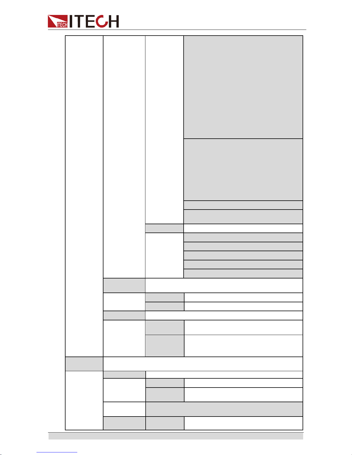
Model
Voltage
Current
Power
Height
IT6512D
80V
120A
1800W
2U
IT6513D
200V
60A
1800W
IT6514D
360V
30A
1800W
IT6515D
500V
20A
1800W
IT6516D
750V
15A
1800W
IT6517D
1000V
10A
1800W
IT6522D
80V
120A
3KW
IT6523D
200V
60A
3KW
IT6524D
360V
30A
3KW
IT6525D
500V
20A
3KW
IT6526D
750V
15A
3KW
IT6527D
1000V
10A
3KW
IT6532D
80V
240A
6KW
4U
IT6533D
200V
120A
6KW
IT6534D
360V
60A
6KW
IT6535D
500V
40A
6KW
IT6536D
750V
30A
6KW
IT6537D
1000V
20A
6KW
Page 18

Quick Start
Copyright ©ITECH Electronics Co., Ltd. 11
Model
Voltage
Current
Power
Height
IT6542D
80V
360A
9KW
15U
IT6543D
200V
180A
9KW
IT6544D
360V
90A
9KW
IT6545D
500V
60A
9KW
IT6546D
750V
45A
9KW
IT6547D
1000V
30A
9KW
IT6552D
80V
480A
12KW
IT6553D
200V
240A
12KW
IT6554D
360V
120A
12KW
IT6555D
500V
80A
12KW
IT6556D
750V
60A
12KW
IT6557D
1000V
40A
12KW
IT6562D
80V
600A
15KW
IT6563D
200V
300A
15KW
IT6564D
360V
150A
15KW
IT6565D
500V
100A
15KW
IT6566D
750V
75A
15KW
IT6567D
1000V
50A
15KW
IT6572D
80V
840A
21KW
24U
IT6573D
200V
420A
21KW
IT6574D
360V
210A
21KW
IT6575D
500V
140A
21KW
IT6576D
750V
105A
21KW
IT6577D
1000V
70A
21KW
IT6582D
80V
960A
24KW
IT6583D
200V
480A
24KW
IT6584D
360V
240A
24KW
IT6585D
500V
160A
24KW
IT6586D
750V
120A
24KW
IT6587D
1000V
80A
24KW
IT6592D
80V
1200A
30KW
IT6593D
200V
600A
30KW
IT6594D
360V
300A
30KW
IT6595D
500V
200A
30KW
IT6596D
750V
150A
30KW
IT6597D
1000V
100A
30KW
Page 19

Quick Start
Copyright ©ITECH Electronics Co., Ltd. 12
2.2 Front Panel Introduction
The 2U models of IT6500D Seri es power supply have same front panels. Other
models, have same panels as 2U Model. The front panel diagram and function
key diagram of 2U Model ar e as follows.
2.3 Keyboard Introduction
IT6500D series power supply different models are same the key function in
front board, schematic graph as follow.
Detailed description of keys
keys
Name and functions
0-9
Numeric button
Shift
Composite key
P-set( Menu)
Power s etting button, used to s et the output power value/menu
functio
n button which used to set the related parameters of
power supply.
V-set( Setup)
Voltage setting button, used to s et the ouput voltag e value/set
the rising tim e and fall time of voltage.
I-set( Function)
Current setting button,used to set the output current value/set
the List function.
Recall( Save)
Callback button, used to r ecall a saved setting par ameter/save
button,used to save a setting parameter.
IT6512D/IT6513D/IT6514D/IT6515D/IT6516D/IT6517D/IT6522D/IT6523D/IT6524D/
IT6525D/IT6526D/IT6527D
1 Power Switch
2 VFD Screen
3 pulsating knob to control voltage, coarse button,fine
botton
4 pulsating knob to control current, coarse button,fine
botton
5 directioin key and OK key
6 function keys and composite key
7 numeric key and Esc key
8 Ventle hole
Page 20

Quick Start
Copyright ©ITECH Electronics Co., Ltd. 13
keys
Name and functions
Meter/( Local)
Meter button,used to switch the display between actual value
and setting value /switch to the loacl mode.
Enter/( Trigger)
Confirm button,to confirm the setting numbers or
functions/trigger button
On/Off( Lock)
Ouput on/off button,used to control the output stat us of power
supply/kelock function button,used to lock the front panel
buttons
Left and right direction button,used t o adjust the location of the
cursor
Up and down direction button,used to select the items of the
menu or increase( decrease)
the output voltage and current
value
OK Confirm button
Esc Return k ey
Dot
2.4 VFD Indicator Lamps Description
IT6500D series power supply VFD i ndicator lamps description as follows:
Flag
Function Description
Flag
Function Description
OFF
Power supply in off mode
Timer
none
CV
Power supply in CV mode
Sense
none
CC
Power supply in CC mode
Ext
none
*
Open the keylock function
Addr
When received command
successfully,
the flag will
display 3 seconds.
Meter
“ Meter” butt ion in on mode
Rmt
Remote control mode
Shift
using composite function
Error
Error occur
Rear
Analog function begin to work
Prot
Protections for OV or OT
SRQ
Serial request query
Trig
waiting for triggering signal
OFF
Power supply in off mode
Timer
none
CW
Power supply in CP mode
-
-
Page 21

Quick Start
Copyright ©ITECH Electronics Co., Ltd. 14
2.5 Rear Panel Introduction
Different models of IT6500D Series power supply have different rear panels.
The 2U rear panel is as shown below. Other models have same rear panels as
2U Model except systemb us ans AC input terminal.
IT6512D/IT6513D/IT6514D/IT6515D/IT6516D/IT6517D/IT6522D/IT6523D/IT6524D/
IT6525D/IT6526D/IT6527D
1 GPIB interface
2 RS232 interface
3 LAN interface
4 USB interface
5 Fan
6 Not for user
7 Earth ( ground) terminal
8 AC power input terminals
9 Not for user
10 Not for user
11 The positive terminal of output
12 Sense terminals
13 The negative terminal of output
14 System bus
15
Analog interface and CAN
interface
2.6 Power-on Selftest
A successful selftest indicates that the purchased power product meets delivery
standards and is available for normal usage.
Before operation, please confirm that you have fully understood the safety
instructions.
To avoid burning out, be sure t o confirm that power voltage match es
with supply voltage.
Be sure to connect the main power socket to the power outlet of
protective grounding. Do not use terminal board without protective
grounding. Before operation, be sure that the power supply is well
grounded.
To avoid burning out, pay at tention to marks of positive and negative
polarities before wiring.
Power Switch Introduction
User can pr ess t he pow er sw i t ch of IT6500D ser i es pow er supply directly to turn
on or turn off the instrument.
The status of Powe switch are as follows.
OFF ON
ON OFF
Page 22

Quick Start
Copyright ©ITECH Electronics Co., Ltd. 15
Selftest steps
Normal selftest procedures:
1. Correctly connect the power cord. Press Power key to start up.
2.
After selftest, VFD displays the output voltage and current status as below:
Error Information References
The following error information may occur when an error occurs during Power
On self-test:
If the EEPROM was damaged, the VFD wil l display “ Eeprom Failure” .
If the syst em s etting data in EEPROM is lost,the VFD wil l display “ Main
frame Init ializ e Lost” .
If the calibr ati on dat a in EEP ROM is l ost , then VF D wi ll displ ay “ Calibration
Data Lost” .
If the lastest operation data in EEPROM is lost, then V FD will display
“ Config Dat a Lost” .
In case of parallel networking faul t, networking will be failed and
“ NETWORKING…” will be prompted.
Exception handling
If the power supply can not st art normally, please check as below steps.
1. Check whether the pow er cord is corr ectl y connected and conf i r m whether
the power su pply is powered.
Correct wiring of power cord = > 2
Incorrect wiring of power cord = > Re-connect the power cord and check
whether the exception is removed.
2. Check whether the pow er turn On. Power key is under “ ” “ ON”
status.
Yes = > 3
No = > Please check the Power key to start power and check whether the
exception is removed.
3. Check whether the terminal resistance (plug) of the syste m b us is correctly
installed.
Yes => 4
No => Please r e-install the terminal resistance. For 2U model , insert the
terminal resistance at any end of the system bus int erface. For other
models, insert the ter minal resistance to the bus Input of the first power
supply system and the bus Output of the l ast power supply system. Restart
the power su pply to see whether the fault isPress [Esc] key to see whether
present fault state can be clear ed. Or, the user can at te mpt t o cl ear the f a ul t
state by rest arting the instrument. Do not restart the instrument until it is
complet ely powered down. If not, contact ITECH engineer.
OFF
0.000V 0.000A
0.0W
Page 23

Function and Features
Copyright ©ITECH Electronics Co., Ltd. 16
Chapter3 Function and Features
This chapter describes in detail the use of the front-panel keys and shows how they
are used to accomplish power supply operation.
3.1 Setting Voltage
The constant voltage range is from 0V to the maximum voltage value. It is very
easy for you to set the constant voltage output. You have 3 solutions to set the
constant voltage value.And when you press[V-set], this button will be lit.
directly input through nu m ber keys
Input the value you want to set and then please press [Enter] or [OK]
button to conf irm.
using knob to set value
Press [V-set] button
Press [Coarse] button( coarse adjustment,change the value in integer bit)
or [Fine] button( fine adjustment,change the value in decimal bit),and then
rotate the knob to set the value
using left and right direction key to set value
Press [V-set] button
Press [Coarse] button( coarse adjustment,change the value in integer bit)
or [Fine] button( fine adjustment,cha nge the value in decimal bi t), move the
cursor by left and right keys, then to adjust values through ▲and▼.
3.2 Setting Current
The constant current range is from 0A to the maximum current value. It is very
easy for you to set the constant current output. You have 3 solutions to set the
constant current value. A nd when you press [I-Set], thi s button will be lit.
directly input through nu m ber keys.
Input the value you want to set and then please press [Enter] or [OK]
button to conf irm.
using knob to set value
Press [I-Set] button
Press [Coarse] button ( coarse adjustment,change the value in integer bit)
or [Fine] button( fine adjustment,change the value in decimal bit),and then
rotate the knob to set the value
using left and right direction key to set value
Press [I-Set] button
Press [Coarse] button ( coarse adjustment,change the value in integer bit)
or [Fine] button( fine adjustment,cha nge the value in decimal bi t), move the
cursor by left and right keys, then to adjust values through ▲and▼.
3.3 Setting Power
The constant current range is from 0W to the maximum power value. It is very
easy for you to set the constant power output. When you press [P-set], this
button will be lit. then you can input the power value by numeric and press
[Enter] or [OK] button to confi rm.
Page 24

Function and Features
Copyright ©ITECH Electronics Co., Ltd. 17
3.4 Output On/Off Button
[On/Off] button is used to control the output state of power supply. If [On/Off]
button is lit,this represents output is open.And in on mode,the indicator
lamp( CC/CV/CW) will be lit.
NOTE
please ensure that the DC source and product under test have been
connected well before you press [On/Off] button.
3.5 Switching Setting Value and Actual Value
[Meter] button is used to switch the display between actual value and setting
value.When [Meter] button is lit,this represents that VFD bo ard display is actual
value.Reversely,if [Meter] button is dark,VFD board display is corresponding to
setting value.
This option allows users to enable an internal fixed timer delay ( 5 seconds) for
the power supply to automatically switch from setting display to measured
display. When enabled, if the power supply output state is ON ( enabled) and if
the display shows setting voltage and current, it will automatically switch to
measured voltage and current display after 5 seconds. Factory default is Off
status.
3.6 Switching Local/Remote Mode
Power supply provides local and remote modes. The two modes can be
switched through communication commands. The d efault setting is local mode.
Local mode: use press keys o n the power supply front panel to operate.
Remote mode: connect the power supply with PC, and operate power
supply through PC. When it’s remote mode, only [Meter],
[Shift]+[Meter]( Local )work, with all the other panel keys not working. It
can be switched to local mode by [Shift]+[Meter]( Local ).The power
supply ’s output parameters won’t be influenced when mode is switched.
3.7 Key Lock Function
[Shift]+[On/Off] ( Lock) button can enable you to lock the front panel buttons,then
VFD will display “ *” . In keylock mode,all buttons will not work except for
[On/Off],
[Meter] and [Shift] buttons. Re-press [Shift]+[On/Off] (Lock) button will release
the keylock function.
3.8 Save/Recall Operation
IT6500D can enable you to save some frequently-used parameters in
nonvolatile memory up to 100 sets.So that you can recall the parameters
quickly.The foll owi ng w ays can help you achieve the save a nd r e cal l oper ati ons:
by pressing composite button [Shift] +[Recall] (Save) button or through
command *SAV,*RCL.Save operation should work in with GROUP.Each
GROUP can save 10set s, IT6500D includes 10 GROUP from 0-9.
Save parameters include setting voltage, setting current, setting power and the
limit val ue of voltage, cur rent and power.
Save method:
Using composite button [Shift]+[Recall] (Save) + number keys 1…9,and then
pressing [Enter] button to save the pre set value into specified memory region.
Page 25

Function and Features
Copyright ©ITECH Electronics Co., Ltd. 18
Using [Recall] (Save) button +number keys 1-9,and then pressing [Enter] button
to recall the saved parameters from specified memory region.
3.9 System Menu
Press the com posite key [Shift] + [P-set] (Menu) to enter the menu function. At
this tim e, VFD displays optional menus. Scroll the VFD screen with Left/Right
key or knob, and the following functions will appear in sequence. Press [Enter]
to enter fun ction options where the scr ee n display locates. Press [Esc] to ret urn
to previous menu.
Menu Menu setting
SYSTEM
System menu
Reset
Restore to factor y default s
Power-On
Set power on parameters
Rst( Def)
Initialize the system
Sav0
Remain last shutdown param eters
Trigger
Set the trigger mode
Manual( Def)
Manual trigger
Bus
Bus trigger
Ext
External trigger
Memory
Work with Recall(Save) button to recall 100 sets saved
parameters
Group = 0
0: represents 0-9sets;
1: represents: 10-19sets,
by parity of reasoning
Buzzer
Set the buzzer function
On( Def)
enable the buzzer funct ion
Off
disable the buzzer f unction
Communicati
on
Select the communication interface
RS232( Def
)
Select RS232 communication interface
Baud rate :
4800/9600/19200/38400/57600/115200
Data bit: 8 O Odd parity 2
Parity bit: None/ E ( Even parity)/ O (Odd
parity)
Stop bit: 1/2
Addr: Addres s=1
USB
Select USB communicatio n inter face
GPIB
Select GPIB communicat ion interface
Address= 0
set the communication
address( 0-31)
LAN
Select LAN communication interface
Page 26
Function and Features
Copyright ©ITECH Electronics Co., Ltd. 19
Info: The information of LAN.
LAN Status: Down
IP Mode: D isconnect
IP Addr: 0.0.0.0
SubNet: 0.0.0.0
Gateway: 0.0.0.0
DNS1: 0.0.0.0
DNS2: 0.0.0.0
MAC: 8C:C8:F4:40:01:E1
MDNS Status:
HostName:
HostDesc:
Domain:
TCPIP::INSTR:
Socket Port: 30000
Config:
IP-Mode: Auto/M anual
Server-Config:
MDNS: On/Off
PING: On/Off
telnet-scpi: On/Off
Web: On/Off
VX-11: On/Off
Raw-socket: On/Off
Restore: R estore to factory defaul ts
Reset: Sa ve all of setting, and the settings
take effect after restart.
CAN
Select CAN communicatio n inter face
250K:
Baud rate
Addr: address of power suppl y
Prescaler: Prescaler
BS1 Value: Not set table
BS2 Value:
Not settable
ReturnMeter
Enables automatic delay to switch display from setting
to measured value ( meter).
Off( Def)
Auto return Meter function disabled.
On
Auto return Meter function enabled
P-Out
Power whether power supply was on
Off( Def)
After power on,the instrument will be in
the off state.
Last
If output was on prior to turning the
power off,the ON state will be resumed
after power on.
CONFIG
Config menu
Load-Status
Setting the internal load status.
Off( Def)
Disables the dummy load ( default).
On
Enables the dummy load.
Static-Curr setting t he static curr ent when output is Off status
Off
Turn off static current function (avoid current
flow-backward)
Page 27

Function and Features
Copyright ©ITECH Electronics Co., Ltd. 20
On( Def )
Tur n on static curr ent function (clear
voltage manti ssa)
Ext- Ctrl
External control mode and related parameter setting
Voltage( D
ef )
Voltage setting mode selection
10V(Def)/5
V
10V or 5V setting mode selection. select by
left/right key.
Resistance
Resistance setting mode selection. 10K or 5K
setting mode selection, select by left/right
key.
10k/5k
Off
Disable or enable this function. Select by
up/down key.
On
Parallel
Parallel mode set up
Single
Single mode
Master
Act as a master mode
Master Mount: total number of instruments
in parallel.
Slave
Act as a slave mode
Filter
Set the display filter frequency of the power supply
Low
Low speed fr equency
Mid( Def )
Middl e speed frequency
Fast
High speed frequency
Sense-Protec
t
Enable sense reversed protection function
Disable
Disable sense reversed protection function
Enable( D
ef)
V = 5V: T he pr ote ct volt age val ue. D i ff er ence
between sense voltage and output voltage.
When exceeds the value, the protection will
be activated.
Delay = 0.1ms( Def ): Protect delay time.
INFO
Product information
Model
Model of power supply
Ver
Software version
SN
Serial number
Last Cal
calibration information for last time
Note
Press
[Shift]+[P-set]( Menu) to view the menu items,press [Esc] to quit menu
operation.Besides,press
[Esc] button can enable you quit the function operation state.
Restored to Factory Setting( >Reset)
This option is used to restore all settings in the system menu to factory setting
values. Press [Enter] to restore to factory setting values. In this case, all set
values in the system will be restored to factory setting values, i.e., the (Def)
mark values.
Configure Power-On State( >Power-on)
When the power-on parameter is set as Rst, at each time of power on, the set
parameters of the power supply will be 0V, 0A and the power rated value. The
parameter setting val ues under Setup and Function menus will also be rest ored
to initial values.
Page 28

Function and Features
Copyright ©ITECH Electronics Co., Ltd. 21
Rst will not initialize the system setting and configuration setting. If Sav0 is
selected, the parameters will be all setting values at the time of last power-off,
including output and input setting values of the power supply.
Trigger Mode ( >Trigger)
Trigger is used for trigger the output of voltage, current and power, and there’re
three kinds of trigger options: Manual, Bus, and Ext. The default settings is
Manual
Manual: the trigger signal will be given by composite keys
[Shift]+[Enter]( Trigger )
Bus: bus trigger mode.
Ext: external signal trigger.
Save Group Operation ( Memory)
Power source can save 100s ets parameters in nonvolatile memory by the save
group setting.This operation provides the customer with a convenient and quick
save/recall using condition.
GRP0: save( recall) power source parameters in 0-9 sets.Press
[Shift]+
[Recall]
( Save)+0-9 numeric keys( [Recall] +0-9 numeric keys to recall the
parameters)
GRP1: save( recall) parameters in 10
th
-19th sets.Press [Shift]+
[Recall]
( Save)+numbers1-9 to save the parameters( [Recall] +numbers1-9 to
recall parameters).Under this condition,number “ 1” represents to save or
recall the 10
th
parameters.Number “ 2” represents to save or recall the
eleventh parameter.GRP2-GRP9 can be understood in the same manner .
Key Sound Set( >Buzzer)
This item can set the buzzer state.On option indicates that when you push
buttons,the buzzer will sound.Off option indicates that the buzzer function is
disabled.Factory default is On option.
Communication Set( >Communication )
Under this item,you can set the concrete communication mode.This unit has
provided multiple communication interfaces: RS232/USB/GPIB/LAN/CAN.Of
which,the GPIB are addressable from 0-31.The baudrate options of RS232 are
4800,9600,19200,38400,57600,115.2K.Data bit is 8bits.Parity bit has three
options: NONE,ODD,EVEN.Please ensure the configuration consistency
between our instrunment and PC,so that you could have a successful
communication.
Return to Meter state( > Return Meter)
This option allows users to enable an internal fixed timer delay ( 5 seconds) for
the power supply to automatically switch from setting display to measured
display. When enabled, if the power supply output state is ON ( enabled) and if
the display shows setting voltage and current, it will automatically switch to
measured voltage and current display after 5 seconds.
Power On Output State (> P-OUT)
This item can set the power on output state. If you select Last item, that
indicates the power on output state is the same with output state before this
item is set. If yo u select Off item, unit will automatically in off mode when you
Page 29

Function and Features
Copyright ©ITECH Electronics Co., Ltd. 22
power on. Default setting is Off item.
Load Setup Option (> Load)
The power supply has an internal dummy load that can be enabled to increase
the speed of the vol tage fal l ti me for high speed t est appli cati ons. Default setting
is Off status.
Load status must be set to On when use adjustable rise time and fall time
speed function.
Setting Filter
This options sets the display filter frequency of the power supply. The filter
function of this series of power supply is averaging calculation. The average
values of different frequencies are different, as shown below: Low: 2
^
16; Mid:
2^14; High: 2^8.
3.10 Setup Menu
Related power supply parameters can be set in Configuring Menu. Details are
as follows:
Voltage/current/power slope
OVP/OCP/OPP
Maximum and mini mum val ues of volt age/ cur rent /pow er
Press [Setup] in the front panel to enter the Source menu for setting.
Setup
Source
Configure menu
Slope
Set the slope
V-Rise: voltage rise slope
V-Fall: voltage fall slope
I-Rise: current rise slope
I-Fall: current fall slope
P-Rise: power rise slope
P-Fall power fall slope
OVP
Over voltage protection
On
Enable over voltage protection
function
V: OVP value
Delay: delay time of protection
Off
Disable over
voltage
protection
function
OCP
Over current protection
On
Enable over current protection
function
I: OCP value
Delay: delay time of protection
Off
Disable over current protection
function
OPP
Over power protection
On( Def)
Enable over power protection
function
P: OPP value
Page 30

Function and Features
Copyright ©ITECH Electronics Co., Ltd. 23
Delay: delay time of protection
Off
Disable over power protection
function
Limit
V-Max
Maximum voltage setting
V-Min
Mini mum voltage setting
I-Max
Maximum current setting
I-Min
Mini mum curr ent setting
P-Max
Maximum power setting
P-Min
Minimum power setting
3.11 Setting Output Rise Time/Fall Time
Rise/fal l ti me i s t he ti me tak en for on e vol t age point to rise/fall to t he ot her und er
the output status is ON. When view the fall time that voltage falls to 0V, set 0V
through [V-set]. Afte r pre s s [Enter] to confirm, voltage will fall based on the set
fall time.
1. Press [Shift] + [V-set](Setup) to enter pow er supply setting screen.
2. Select “ Source” .
3. Select “ Slope” .
You can set the rise/fall times for voltage, current and power. The unit is
second ( S). Each setting can be selected through the Up/Down key. Adjust
the rise edge time through the numeric key, Up/Down key or knob. After
input, press [Enter] or [OK] for confirmation.
V-Rise/ V-Fall: Voltage ri se/fall slope.
I-Rise/ I-Fall: Current rise/fall slope.
P-Rise/P-Fall: Power rise/fall slope.
Note
The drop rate of the voltage is affected by the internal load. Enable the internal load to get
the drop rate of the voltage up. Please refer to 3.9 System Menu for more detailed setting.
3.12 Protection Function
OVP, OCP, OPP and OT P are provided in the IT6500D Series power supply.
IT6500D Series provides OVP, OCP, OPP. In addition, this power supply also
provides OTP, Sense reverse protection, power-down protection and input
under-voltage protection. In case of protection, please check fault reason and
remove fault. Press the [Esc] key to disarm protection status.
OVP
User can enable the over voltage protection function and set the protection
value i n setup men u, Over V ol t age Prot ec ti on wi ll be tri ggered when the voltage
exceeds the protection value. Many reasons could cause a over voltage
protection. For example, caused by internal defect, misoperation, or too high
external voltage.
Once the power supply is over voltage protect ed,will the output b e shut down at
once,and “ Prot” indicator lamp will be lit, and prompt “ Over Voltage” will
be displayed on VFD screen. Please avoid inputing a external voltage higher
than 120% rated value, or the instrument will be damaged.
When the power source is in OVP state, you should check the external cause
Page 31

Function and Features
Copyright ©ITECH Electronics Co., Ltd. 24
firstly. When the external factors are excluded, please press [On/Off]
button.Then the unit could have a output voltage again.If in remote control
mode,you should clear the OVP state,then could you open the output by OUTP
ON command.
Set the OVP voltage value as follows:
1. Press the composite key [Shift] + [V-set] (Setup) to enter t he setup Menu.
2. Select “ Source” in the menu and press [Enter] for confirmation.
The power supply can set i ts OVP.
3. Select OVP with Left/Right key and press [Enter] for confirmation.
4. Select On to enable OVP function and press [Enter].
5. Set OVP voltage value with numeric key and press [Enter] for confirmation.
6. Set OVP delay time with numeric key and press [Enter] for confirmation.
Press [Esc] to exit menu setting.
OCP
User can enable the over current protection function and set the protection
value in setup menu, Over Current Protection will be triggered when the current
in circuit exceeds the protecti on val ue.
Once the power supply is over voltage protect ed,will the output b e shut down at
once,and “ Prot” indicator lamp will be lit, and prompt “ Over Current” will
be displayed on VFD screen. At same time, t he beeper will be on.
Set the OCP current val ue as follows:
1. Press the composite key [Shift] + [V-set] (Setup) to enter t he setup Menu.
2. Select “ Source” in the menu and press [Enter] for confirmation.
3. Select OCP with Left/Right key and press [Enter] for confirmation.
4. Select On to enable O CP function and press [Enter].
5. Set OCP current value wi t h numeri c key and pr es s [Enter] for confirmation.
6. Se t OCP delay tim e with numeric key and press [Enter] for confirmation.
Press [Esc] to exit menu setting.
OPP
OPP is a protection measure taken when the actual power exceeds the rated
power of the power supply. Under OPP, the power supply output will be
switched off and VFD indicator “ Prot” will be lighted on. In addition, the VFD
display screen will display “ Over Power” .
This series of power supply can set OPP.
Set the OPP current val ue as follows:
1. Press the composite key [Shift] + [V-set] (Setup) to enter t he setup Menu.
2. Select “ Source” in the menu and press [Enter] for confirmation.
3. Select OPP with Left/Right key and press [Enter] for confirmation.
4. Select On to enable OPP function and press [Enter].
5. Set OPP power value with numeric key and press [Enter] for confirmation.
6. Set OPP delay time with numeric key and press [Enter] for confirmation.
Press [Esc] to exit menu sett ing.
Page 32

Function and Features
Copyright ©ITECH Electronics Co., Ltd. 25
Over-temperature protection
When internal power device of instrument is higher than about 90 °C, the
instrument is under temperature protection. At this time, the instrument will
automatically be O FF and VFD will display “ Over Temperature” .
Power down protection
With power-down protection, when the instrument power supply is switched off
and the instrument detec ts power-down status, the instrument will immediately
execute output switch-off and the instrument interface will display
“ power-down” .
Under Voltage Protection
When inter nal vol t age i s low due t o i nt ernal fault or when AC i nput vol t age i s l ow,
the instrument will initiate the under-voltage protection. Or when 110V AC
power supply is connected, the instrument output function is limited. When the
set output power exceeds limit value, the instrument will also initiate
under-voltage protection status. In the case of under-voltage protection, the
instrument interf ace w ill display “ Under Voltage Prot” .
Sense Reverse Protection
When the dif fer ence bet wee n out put t er minal voltage and sens e r e mote vol tage
exceeds the specified v oltage and lasts for 10ms, sense reverse protection will
be enabled. The power supply output will be immediately switched to Off and
the buzzer will sound if the sense terminals are reversed. The display screen
will display “ Sense Reverse Prot” . Press [Esc] to clean the protection.
When the power sour ce is in Sense Re ver se Pr ote ct i on st ate, y ou shoul d che ck
the whether the polarities are connected reversely or not firstly. When the
polarities c onnect correctly, please press [On/Off] button. Then the unit could
have a output voltage again.
The voltage difference between output terminal and remote sense terminal of
each model is not the same. The detailed value is shown in the next table.
When the remote sense terminal is connected reversely, the maximum voltage
will not ex ceed the sum of set voltage and the difference voltage.
IT6512D~IT6592D
5V
IT6513D~IT6593D
5V
IT6514D~IT6594D
7V
IT6515D~IT6595D
10V
IT6516D~IT6596D
15V
IT6517D~IT6597D
20V
3.13 Setting Maximum and Minimum Values
The maximum voltage of the power supply ranges from V-min to full-rated
output voltage. Press the composite key [Shift] + [V-set] (Setup) to enter the
Configuring Menu for setting maxim um and minimum values of power supply
voltage, cur rent and power.
Set the maximum and minimum voltages as f ollows:
Page 33

Function and Features
Copyright ©ITECH Electronics Co., Ltd. 26
1. Press the composite key [Shift] + [V-set] (Setup) to enter the Configuring
Menu.
2. Select “ Source” in the menu and press [Enter] for confirmation.
3. Select Limit with Left/Right key and press [Enter] for confirmation.
4. Set the V-Max with numeric key and press [Enter].
5. Set the V-Min with numeric key and press [Enter] for conf irmation.
Or, select the maximum/minimum curr ent or power with Arrow key.
6. Set maximum/minimum current or power with numeric key or press [Esc]
to exit menu setting.
After the maxim um/minimum voltage is set, the output voltage can only be
set within this range. Vmax factory setting is the rated output voltage of
corresponding model of the power supply. V-Min is 0V.
3.14 Charge Protection
This power supply is applicable to battery charge test and provides charge
protection during battery charge test. Even when the internal load is activated,
the UUT will not be discharged. During charge protection, the power supply
switches off output as f ollows.
1. Power output is switched off ( On/Off key is lighted off) and power supply
will stop output.
2. The internal l oad discharges the capacit y energy at power output through a
small current.
When abnormal capacity energy discharge is detected, the UUT connected
at the output t ermi nal i s a batt ery or ot her energy stor ag e de vice s. Step 3
When capacity energy discharge of the power supply is normal, it means
that no energy st ora ge de vice i s f oun d. C ont i nue t o di sch arge t h e curr e nt t o
0V. End
3. The power supply will automatically switch off the internal load.
This protection function forbids UUT d ischarge to guarantee device safety.
It also avoi ds insufficient charge during battery charge test.
3.15 LIST Operation
IT6500D LIST mode comprises 10 files ( File1-File10) in total, and each has 10
waves. Each wave has 10 steps. You need to edit the voltage, current, pulse
width and rise/fall slope of each step. Each wave can set repetition, so does
each list file. Ten wave files can be linked in sequence under one list.
Relationship between List file and wave file i s shown below.
Page 34

Function and Features
Copyright ©ITECH Electronics Co., Ltd. 27
List file can select any one from 100 waves. Each List file can select 10 wave
files at most and combine them into a List fil e based on sequ ence.
Each wave file has ten steps. The List file can select the wave file and set the
count of repetitions to be executed.
List funct ion menu is as follows.
List
List funct ion menu
On/Off
List funct ion switch
Recall
List file recall
Recall List File: Need to recall list fi le
number.
EditFile
List file edit
Repeat: count of List file repetitions
Wave Count: total count of waves
contained in this List fi le.
1st Wave Select: number of the first wave
selected
1
st
Wave Repeat: count of repetitions of the
first wave select ed
Yes/No: save to the file or not
EditWave
Wave fi le edit
Recall W ave: Need to recall Wave file
number.
Step Count: total count of steps contained
in the Wave file
Step1 Voltage: Voltage setting of step 1
Step1 Current: Current setting of step 1
Step1 Width: Width setting of st ep 1
Step1 Slope: Slope sett ing of step 1
Save to Wave: save to the Wave file
Wave edit and List edit have no order of priority.
Editing Wave
List file can arrange and link several Wave files. The user can pre-edit
several Wave files and select edited wave file that meets requirements
during usage. In this series of power supply, at most 100 wave files can be
edited.
Take an example for 3 steps, the steps of editing Wave file are as follows:
1. Press [Shift]+[I-set]( Function) to enter List operation.
2. Press to select EditWave from the menu, and press [Enter] for
confirmation.
3. Press numeric key to input the number of Wave file under edit, where
Recall W ave= 01, and press [Enter] for confi rmation.
4. Press numeric key to input total count of steps for the current Wave file,
where Step Count=03, and pr ess [Enter] for confirmation.
5. Press the numeric key to set the voltage, current, slope and width of the
Wave step 1 in seque nce.
Step1 Voltage = 1V
Step1 Current = 1A
Page 35

Function and Features
Copyright ©ITECH Electronics Co., Ltd. 28
Step1 Width = 1s
Step1 Slope = 0.1s
6. After editing the above parameters in step 1, continue to edit the same
parameters for step 2 and step 3. Count of steps is up to customer
requirements. At most 10 steps can be edited. The edited Step Count shall
be consistent with the one defined by the customer.
7. Select Yes. After editing, select Yes or No. Select Yes to save to the Wave
file. Select No not to save and return back to the List Setting screen.
8. Select Save to Wa ve to save, an d press [Enter] for confirmation.
Editing List File
List file editing means to arrange and link several Waves in certain
sequence.
Take an example f or 3 wave files, the steps of editing list file are as follow s:
1. Press [Shift]+ [I-set]( Function) to enter List operati on.
2. Press to select EditFile from the menu.
3. Press the numeric key to set the count of repetitions in executing this List
file. For example, if t here are 2 repetitions, Repeat = 2.
4. Press the numeric key to set the count of Waves contained in this List. For
example, Wave Cont = 3.
5. Press the numeric key to input the number and count of repetitions of the
first Wave selected.
1
st
Wa ve Select = 02
1
st
Wave Repeat = 1
6. Press the numeric key to input the number and count of repetitions of the
second Wa ve sel ecte d.
2
nd
Wave Select = 02
2
nd
Wave Repeat = 1
7. Select the Wave arranged and count of repetitions in sequence. The Wave
count and arrangement sequence of each List file can be defined by the
customer ba sed on r equi r ement s. A List fil e can link 10 Waves at most. T he
edited Wave count shall be consistent with the one defined by the
customer.
8. Select Yes. After editi ng, sel ect Yes or No. Select Yes to save t o t he Li st fi l e.
Select No not to save and return back to the List Setting screen.
9. Select Save to Fil e = 01 to save, and press [Enter] for confirmation.
Run List File
After editi ng List file, the user needs to set the tri gger mode and run Li st f unction.
Return to the main screen for triggering. Detailed steps are as follows:
Before starting up List function, please set trigger mode first. See Section
3.9 for trigger source.
1. Press the composite key [Shift]+[P-set](Menu) to enter the System Menu.
2. Select SY STEM and press left and right key to select Trigger.
Set the required tri gger mode. Defaul t trigger mode is Manual.
Trigger the List file as follows
Page 36
Function and Features
Copyright ©ITECH Electronics Co., Ltd. 29
1. Press [Shift]+ [I-set]( Function) to enter List operati on.
2. Press to select Recall from the menu, and press [Enter] for
confirmation.
Recall File Name = 01
3. Press Arrow key to select Off. Press [Enter] for confirmation. Then, Off is
changed to On. List function is switched on.
On Recall EditFile E ditWave
4. Press [Esc] back to the main screen. Press [On/Off] to switch on power
output. The screen is displayed as follows.
0.00V 0.00A
0.0W List
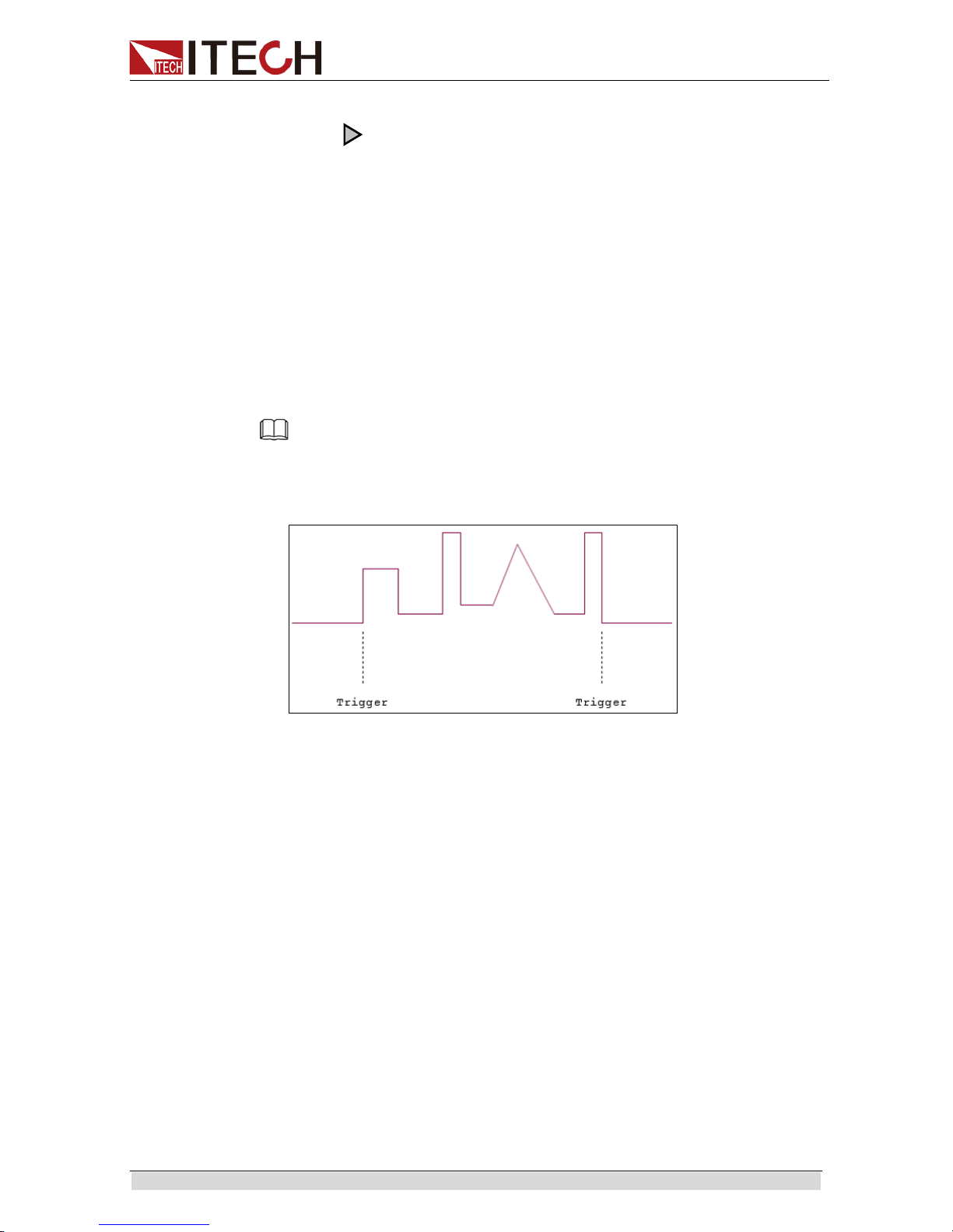
5. Press [Shift]+ [I-set]( Trigger) for triggering. The VFD Trig is lighted up.
NOTE
If On Recall EditFile EditWave is displayed under LIST MENU or the external analog control
function is switched on, neither List nor Wave file editing is accessable. In this case, change
On Recall EditFile EditWave to Off Recall EditFile EditWave before operation.
Diagram of LIST Output Wave
3.16 Parallel Operation
This series of power supply supports mutual parallel operation of same models
and to increase output power and output current. In addition, active current
sharing is provided for parallel instruments.
The figure below shows 3 pcs power supplies in parallel, in which, the system
bus is used for master-sl ave connection.
Fig.1 Schematic Diagram of 3 Pcs Power Supplies in Parallel
Page 37

Function and Features
Copyright ©ITECH Electronics Co., Ltd. 30
The master-slave connection for configuring 3 pcs power supplies is as follows:
1. Configure one power supply as the Master and the other power supplies as
Slave. Press the composite key
[Shift]+[P-set](Menu) to enter the System
Menu.
Press the Right key to select “ CONFIG” and press
[Enter] to enter the
Configuring Menu.
2. Press the Right key to select “ Parallel” and press [Enter] for parallel
setting.
Single: Single mode.
Slave: Salve mode.
Master: Master mode. If Master mode is selected, you need to set the
number of Salves for the Master.
Mount: total number of instruments in parallel. For example, Mount=3.
3. After setting of host and slave, switch off the power supply. Connect the
networking.
Connect the networking as shown above. Please connect the network after
parallel setup. Otherwise, at start up, the power supply will detect parallel setup
fault and f ail to start up.
When connecting the system bus, please note the built-in terminal
matching resistance at the rear panel. If the resistance is removed,
the instrument may not work properly. The user can install the
terminal matching resistance on the Input end of the first system bus
and the Output end of the last system bus.
The system bus interface is not isolated from the output electrode.
After power on, it is not allowed to insert or pull out the bus and
termi nal matching resistance.
3.17 Rear Panel Terminal Functions
If the tested instrument consumes large current, a large voltage drop will be
detected in connection line between tested instrument and power supply
Page 38
Function and Features
Copyright ©ITECH Electronics Co., Ltd. 31
terminal. To ensure measurement accuracy, a remote sense measurement
terminal is provi ded at pow er suppl y rear panel to compensat e vol t age drop l ost
in wir e.
When the power supply is used for measuring battery charge in actual
applications, the voltage drop of the wire will lead to voltage inconsistency of
both ends and inconsistency of the cutoff voltage of power supply and the
actual voltage of battery, resulting in inaccurate measur ement.
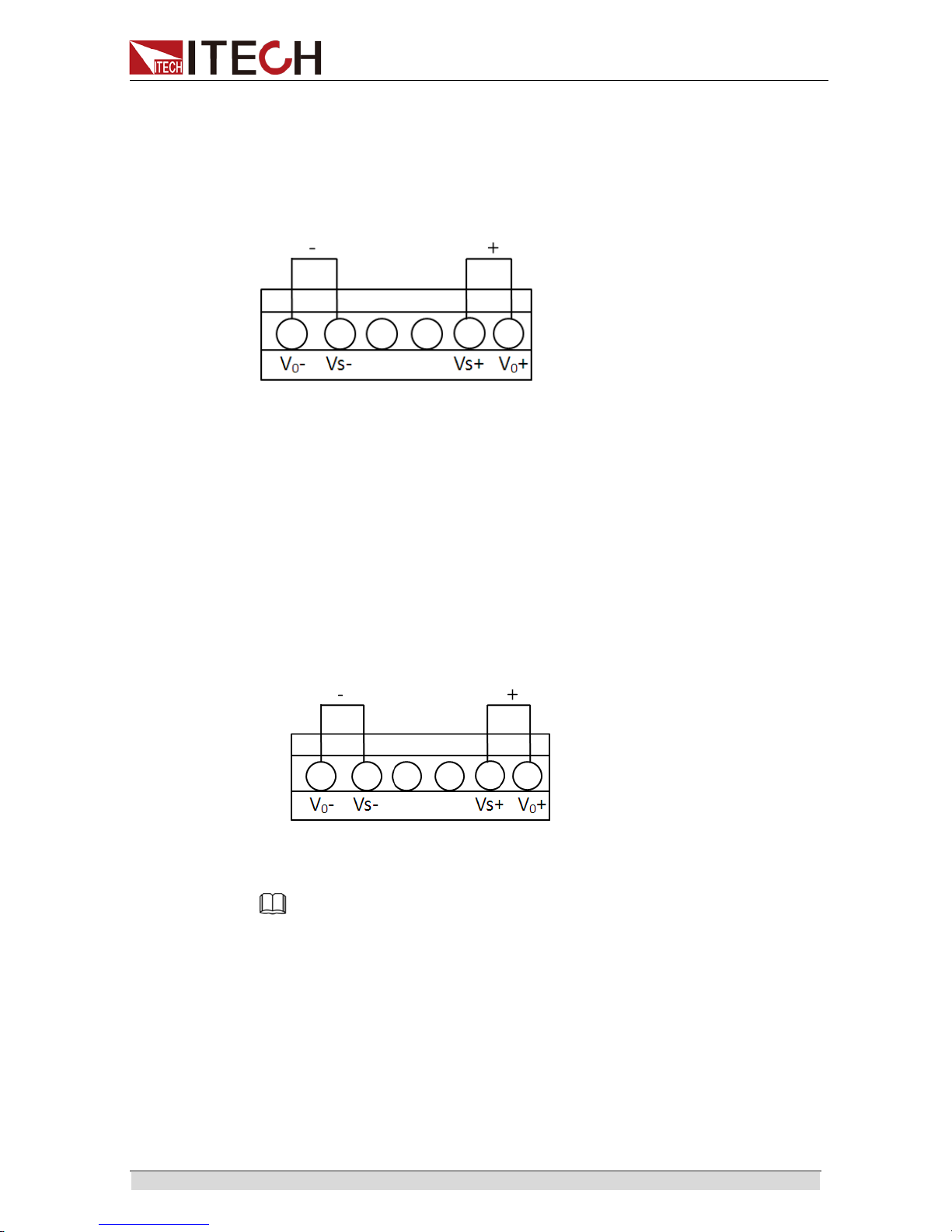
Vo+,Vo-: output terminals
Vs+,Vs-: remote sense termi nal
When using the remote sense function,please cut off the connection wire
between Vo+ and Vs+,so will the li ne between Vo- and Vs- terminals.Then
extending lines from Vs+ to the positive terminal of undertested product
and line fr om Vs- to the negat ive ter minal of undertested product.
Use local sense:
Local sense doesn’t compensate the voltage drop on the connection wire, the
operation is:
1. Connect the V o+ an d Vs+ , Vo- and Vs- for short ci r cuit usi ng t he short cli ps
on the back pa nel of t he i nst r ument or el ect ri c w ir e. Whe n using local sense,
the romote sense terminal can not be disconnected.
illustrated below.
2. Connect the the positive and negative ter minals of the rear panel to the
DUT.
Note
DO not disconnect the wires if remote sense is not used. Doing so will cause erratic behavior
and may damage the power supply under certain conditions
Use remote sense:
Disconnect the wires between Vo+ and Vs+, and Vo- and Vs- pins if you want
to use remote sense function.Then lead a wire from Vs+, Vs- pins and connect
to the DUT.
1. Disconnect the wires/short clips between Vo+ an d Vs+, Vo- and Vs-.
2. Connect the VS+ to the DUT’s positive ( +) terminal, and connect the
VS- to the DUT’s negative ( -) terminal.
3. Connect wires from Vo+ , Vo- to the device under test.
Page 39

Function and Features
Copyright ©ITECH Electronics Co., Ltd. 32
NOTE
In order to ensure the stability of the system, using armored twisted pair cable between
the remote sense terminal of IT6500D and DUT.
Please note that the positive and negative polarity when wiring, otherwise it will damage
the instrument!
Remote Sense Protection( >Sense-Protect)
The power supply output will be immediately switched to Off and the buzz er will
sound if the sense terminals are reversed. The VFD display screen will display
“ Sense Reverse Prot” . And please pre ss [On/Off] to clean the protection.
When power supply in sense reverse protection state, please check the anode
and cathode of the sense terminal must be connected properly.
3.23 Analogue Interface (Enhanced Isolation)
A DB25 analog interface is set at the rear panel of the power supply, through
which, you can connect the external voltage (0V-5V/0V-10V) or external
resistance (0KΩ-5KΩ/0KΩ-10KΩ) to program output voltage or current on 0-full
range. At the same time, with analog monitoring function (0V-5V/0V-10V), you
can monit or the output vol tage or current on 0-full range.
Analog signal bandwidth is less than 100Hz,. support any waveform within
signal bandwidth. When the program signal frequency or amplitude exceeds
output capacity, the output amplitude will be auto m aticall y limited.
In parallel operation, you can program or monitor output through the host
analog interface. The 0V-5V/0V-10V program and monitoring range is changed
to 0-full range of paralle l machine. Safe electrical isolation is set between this
analog interface and output electr ode.
To run this funct ion, you need to set the para meters below :
Monitor
10V(Def)
10V monitoring mode options
5V
5V monitoring mode options
Ext- Ctrl
External control mode and related p arameter setting
Voltage (Def)
Voltage setting mode selection
10V(Def)/5V
10V or 5V setting mode selection, select
by Left/Right key.
Page 40

Function and Features
Copyright ©ITECH Electronics Co., Ltd. 33
Resistance
Resistance setting mode selection
10k(Def)/5k
10K or 5K setting mode selection, select
by Left/Right key.
Off
Disable or enable this function. Select by
up/down key.
On
The above parameters can be selected through the co nfiguration menu.
1. Press the[Shift]+[P-set] ( Menu) to enter the menu.
2. Press the Right Key to select CONFIG and press [Enter] to enter the
configurat ion menu;
3. Press the Right Key to select the Ext-Ctrl and press [Enter] to enter the
configuration of external analog parameters. When setting every item,
please use the Up/Down Key for selection.
After selecting the Ext-Ctrl as “ On” , exit the Menu. At this time, the R ear
indicator on the VFD status bar will be lighted on and the right corner will
display “ Analog” .
DB25
Pin
Name
Instruction
Pin 1 and Pin
14
CANH
CANL
Pin 1 used for CAN H interface, and Pin 14 used for
CAN L interface.
Pin 2
+12V
Power supply output 12V, driving capacity 0.1A
Pin 3
Shut Off
Used for switching off the function under emergency
status (In general circumstances, the pin is suspended,
and defaulted to low level); when external high level is
connected, output is off.
Pin 15
EXT ON
Used for controlling output On/Off of the power supply;
default setting is high level. Output is controlled by
On/Off; when external low level is connected, or when it
is short circuited to DGND, output is switched off. At this
time, setting of output On/Off fails.
Pin 16
Power OK
Used for indicating whether the power output is normal;
if so, output 5V; in case of power supply failure, output
0V.
Pin 17
TrigIN
Input signal of reverse protection mode. When input is
low level, alarm "OutPut Reverse Protect” fault.
At the mean while, in external trigger mode, when input
is low level, then actualize trigger function.
Page 41

Function and Features
Copyright ©ITECH Electronics Co., Ltd. 34
Pin 6
TrigOUT
Output signal of reverse protection mode. When power
supply output is On, this pin outputs high level; when
this power supply output is Off, this pin outputs low level;
it can be used for synchronous control of On/Off for
other devices with driving capacity of 5V/5mA
Pin 18
+5V
The power supply outputs 5V voltage, which is used for
digital power supply with driving capacity of 0.1A.
Pin 19 and
Pin 20
CV_CC+
CV_CC-
The output between these tw o pins is used for ind icating
the working status of power supply; under CV mode, the
output between these two pins is 5V; and under CC
mode, - 5V.
Pin 21
Voltage
Program
( Voltage
setting)
Output voltage of analog control:
In setting the Voltage and 10v, the input analog range
should be 0-10V voltage,
and the regulated output
voltage should be from 0 to full range;
In setting the Voltage and 5v, the
input analog range
should be 0-5V voltage,
and the regulated output
voltage should be from 0 to full range;
In setting the Resistance and 10K,
the input analog
range should be 0-10K resistance, and the regulated
output voltage should be from 0 to full range;
In setting the Resistance and 5K,
the input analog
range should be 0-5K resistance,
and the regulated
output voltage should be from 0 to full range;
Pin 22
REF_10V
The 10V reference voltage output by the power supply
can be connected to a resis
tance subdivision for analog
control.
Pin 23
Current
Program
( Current
Setting)
Output current of analog control:
In setting the Voltage and 10v,
the input analog range
should be 0-10V voltage,
and the regulated output
current should be from 0 to full range;
In setting the Voltage and 5v,
the input analog range
should be 0-5V voltage, and the regu late d o ut put current
should be from 0 to full range;
In setting the Resistance and 10K,
the input analog
range should be 0-10K resistance, and the regulated
output current should be from 0 to full range;
In setting the Resistance and 5K,
the input analog
range should be 0-5K resistance,
and the regulated
output current should be from 0 to full range;
Pin 24
Voltage
Monitor
( Voltage
monitoring)
The actual value from moni toring is the corresponding
monitor voltage value. For example,
when the analog
voltage is 10V, power supply control voltage 0~80V and
the power supply output voltage 20V, this pin will output
2.5V voltage. Similarly, when the analog voltage is 5V,
control voltage 0~80V and the power supply output
voltage 20V, this pin will output 1.25V voltage.
Pin 25
Current
Monitor
( Current
monitoring)
The actual value from moni toring is the corresponding
monitor voltage value. For example, when th
e analog
voltage is 10V, power supply control current 0~120A
and the power supply output current 12A, this pin will
output 1V voltage. Similarly, when the analog voltage
is 5V, control current 0~120A and the power supply
output voltage 12A, this pin will output 0.5V voltage.
Pins 9, 10,
11, 12 and
13
Connection
to AGND
Ground wires for analog interfaces ( including Pin 21
VPRG, Pin 22 REF_10V, Pi n 23 IPRG, Pi n 24 VMON,
Pin 25 IMON).
Pins 4, 5, 7,8
Internal
connection
to DGND
Ground wires for Pin 15 EXT ON, Pin 3 SHUT OFF, Pin
16 POWER OK, Pin 17 TrigIN, Pin 6 TrigOUT,Pin 19
CV_CC+ and Pin 20 CV_CC-.
Page 42

Function and Features
Copyright ©ITECH Electronics Co., Ltd. 35
Voltage Setting ( Voltage Program)
This function enables change of voltage output through external analog signal
by connecti ng ex ter nal DC volt age ( under voltage mode) or an external r esi st or
( under resistor mode) to Pin 21. To enable this function, the output control
should be under the external analog control mode. Used for controlling the
external voltage range of full-scale output voltage or the resistor can be
selected fr om 0~5V/0~10V or 0~5KΩ/0~10KΩ. To switch on the voltage setting,
open the MENU ( Menu) → CONFIG ( Configure) → Ext-Ctrl ( External Analog
Control). Press the Right Key to select Voltage ( or Resistance). Press the
Up/Down Key to select the voltage mode or resistor mode.
Voltage Mode
Under voltage mo de, the user can set the voltage output value of power supply
through Pin 21.
Resistor Mode
Pin 2 1 and Pin 13 ( GND wire) can be connected to a resistor for setting the
output voltage value of t he power supply.
To set the 0~5V/0~10V or 0~5KΩ/0~10KΩ external analog setting range, open
the MENU ( Menu) → CONFIG ( Configure) → Ext-Ctrl ( External Analog
Control). Press the Right Key to select Vol tage ( or Resistance).
Press the Right Key to select 5V/10V or 5KΩ/10KΩ within the full scale scope.
Current Setting ( Current Program)
This function enables change of current output through external analog signal
by connecti ng ex ter nal DC volt age ( under vol tage mode) or an exter nal r esi st or
( under resistor mode) to Pin 23. To enable this function, the output control
should be under the external analog control mode. Used for controlling the
external voltage range of full-scale output voltage or the resistor can be
selected fr om 0~5V/0~10V or 0~5KΩ/0~10KΩ. To switch on the curr ent setting,
open the MENU ( Menu) → CONFIG ( Configure) → Ext-Ctrl ( External Analog
Control). Press the Right Key to select Voltage( or Resistance). Press the
Up/Down Key to select the voltage mode or resistor mode.
Voltage Mode
Under the voltage mode, t he user can set the voltage output value of the power
supply thr ough P in 23.
Page 43

Function and Features
Copyright ©ITECH Electronics Co., Ltd. 36
Resistor Mode
Pin 2 3 and Pin 13 ( GND wire) can be connected to a resistor for setting the
output voltage value of t he power supply.
To set the 0~5V/0~10V or 0~5KΩ/0~10KΩexternal analog setting range, open
the MENU ( Menu) → CONFIG ( Configure) → Ext-Ctrl ( External Analog
Control).
Press the Right Key to select Voltage( or Resistance).
Press the Right Key to select 5V/10V or 5KΩ/10KΩ within the full scale scope.
Voltage monitoring
This function enables monitoring of voltage output via Pin 24 or the GND pin
( i.e., Pin 13), which can be co nnected to a digital voltmeter ( DVM). To use this
function, the output control should be under the external analog control mode.
The output voltage monitoring range ( which reflects the power supply output
voltage fr o m zero t o ful l scal e) can be sel ected f ro m 0-1 0V or 0-5 V. To switch on
the monitoring range setting, open the MENU ( Menu) → CONFIG ( Configure)
→ Monitor ( External m onitor mode). Press the Right Key to select Voltage( or
Resistance).
Press the Right Key to select the output voltage monitoring range ( 0~10V or
0~5V).
The connect ion setting of digital voltmeter is shown below.
Current monitoring
This function enables monitoring of current output via Pin 25 or the GND pin
( i.e., Pin 13), which can be co nnected to a digital voltmeter ( DVM). To use this
Page 44

Function and Features
Copyright ©ITECH Electronics Co., Ltd. 37
function, the output control should be under the external analog control mode.
The output current monitoring range ( which reflects the power supply output
current fr om zero t o f ull scal e) can be selected from 0-10V or 0-5V. To switch on
the monitoring range setting, open the MENU ( Menu) → CONFIG ( Configure)
→Monitor ( External monitor mode).
Press the Right Key to select the output current monitoring range ( 0~10V or
0~5V).
The connect ion setting of digital voltmeter is shown below.
Page 45

Remote Control
Copyright ©ITECH Electronics Co., Ltd. 38
Chapter4 Rem ot e Cont r ol
IT6500D hav e five standard com munication interfaces: RS232, USB, GPIB,
LAN and CAN. The customer can choose any one accor ding to his demands.
4.1 RS232 Interface
Using a cable with two COM ports to connect power supply and PC.Then
please press [Shift] +[P-set] ( Menu) button to enter the menu to configure the
communication parameters.You could do the secondary development with all
SCPI commands.
Note
The setup about RS232 in the program should agree with the configuration in the system
set.If you want to change the communication parameters,please press [Shift] +[P-set]
( Menu) button to enter the system set.
RS-232 Data style
RS232 with start bit and stop bit.The start bit and stop bit can not be
edited.While you could select the odd parity or even parity under the system
set.
Odd or EVEN options have been saved i n the nonvolatile memory.
Baudrate
Edit baudrate: press [Shift] +[P-set] ( Menu) t o enter the menu setu p,you could
select the baudrate amon g the following options:
4800/ 9600/ 19200/ 38400/ 57600/ 115200
RS-232 connection
Please use a straight-through RS232 cable w ith DB9 interf ace and connect the
RS232 serial port with the controller’s serial port( for example.PC). Form 2-2
gives a detailed description for each pin.
RS-232 pins description
Pin
description
1
connectionless
2
TXD,transmit data
3
RXD,receive data
4
connectionless
5
GND
6
connectionless
7
connectionless
8
connectionless
9
connectionless
RS-232 Troubleshooting:
If you meet some problems when communicating with PC by RS232
Page 46

Remote Control
Copyright ©ITECH Electronics Co., Ltd. 39
interface,please check the following items:
Please chec k the paramet ers setting
PC and power supply must have the same configuration in the following
items: baudrate, parity bit,data bit and flow control.Please note that
power supply has been configured with a start bit and stop bit( the two
values are fixed).
Check the cable
Ensure you have used the correct communication cable.Please pay
attention that some cable may not have a correct internal wiring even it is
with a appropriate DB9 interface.
The RS232 communication cable should have b een connected to a correct
serial por t of the PC.
Communication Setup
Please ensure the PC and power supply have the same configuration in the
following items.
baudrate: 9600( 4800, 9600, 19200, 38400, 57600, 115200).You could enter
the system me nu to set the baudrate.
Data bit: 8
Stop bit: 1
Parity bit: ( none, even, odd)
EVEN 8 data bits have even parity
ODD 8 data bi ts have odd parity
NONE 8 data bits have no par ity
Native machine addr es s: ( 0 ~31, factory default is 0)
Parity=
None
Start Bit 8 Data Bits Stop Bit
4.2 USB Interface
Use a cable with two USB ports to connect power supply and PC.You can
program through USB interface to achieve all functions of power supply.
The functions of USB488 interface are as foll ow s :
Interface is 488.2 USB488 interface
Receive the following request: REN_CONTROL, GO_TO_LOCAL, and
LOCAL_LOCKOUT
When the interface receives MsgID = TRIGGER USBTMC command,it
will tr ansmit the TR IGGER command to t he function layer
The functions of power supply’s USB488 are as follows:
receive all SCPI commands
device is SR1 enabled
device is RL1 enabled
device is DT1 enabled
4.3 GPIB Interface
Use a IEEE488 bu s t o conne ct GPI B i nt erface s of pow er suppl y and PC. Pl ease
ensure that the screws have been screwed down in order to have a full
Page 47

Remote Control
Copyright ©ITECH Electronics Co., Ltd. 40
connecti on. T hen press [Shift] +[P-set] ( Menu) t o enter t he syst em menu t o set
the address.The address range of power supply is 0-31.After you set the
address,please press [Enter] button to confirm.GPIB address is saved in
nonvolatile memory.
4.4 LAN Interface
Press [Shift] +[P-set] ( Menu) button to enter the system set. Please select
“ LAN” in the Communication from System and then configure Gateway, IP,
Mask and SocketPort in the LAN option.
Connect the LAN interface of power supply to the computer with a reticle
( crossed). The gateway address should be consistent with that of the PC, and
the IP address should be at the same network segment with the PC’s IP
address.
4.5 CAN Communication Port
There is one DB25 interface at the rear panel, and the pin definition is shown
below. The user can use this terminal for PC connection; to activate
connection, be sure that the values set in the System menu are same as the
corresponding values set in PC.
Note
CAN setting in the program shall be consistent with the one set in the System menu of front
panel. To query and change, press the c omposite key [Shift] + [P-set]( Menu) to enter the
setting screen in System menu for query and change. For details, refer to 3.9 System Menu.
Baud Rate
In the front panel [Shift] + [P-set]( Menu), und er the Sy stem men u, the user can
select one Baud rate stored in NVM:
20K|40K|50k|80k|100k|125k|150k|200k|250k|400K|500K|1000K
CAN Pin Definition
Use DB25 interface for connection. CAN interface pin is as follows.
CAN interface pin
Pin No.
Description
1
CANH
14
CANL
CAN Troubleshooting:
If CAN connection fails, check that:
1. The PC and power supply have same Baud rate.
2. Appropriate interface pin or adapter is used, as described in CAN
connector.
3. The interface cable is correctly connected ( CAN_H to CAN_H, CAN_L to
CAN_L).
Check whether 120 Ω terminal resistance is connected.
Setting Communication
Before running communication, please match the power supply parameters
with the PC parameters as s hown below.
Baud rate: 10K( 20K, 40K, 50K, 80K, 100K, 125K, 200K, 250K, 400K, 500K,
500K). You can enter the System menu through panel and set the
Page 48

Remote Control
Copyright ©ITECH Electronics Co., Ltd. 41
communication Baud rate
Addr.: 1-127
Prescale ( Pres): Not settable. Change with Baud rate setting.
PTS ( BS1): Not settable. Change wit h Baud rate setting.
PBS ( BS2): Not settable. Change with Baud rate set ting.
Baud rate
( Prescale)
PTS
PBS
10k
300
1
6
20k
150
1 6 40K
75 1 6
50K
60 1 6
80K
75 1 1
100K
30 1 6
125K
30 0 5
200K
15 1 6
250K
15 1 5
400K
15 1 1
500K
6 1 6
1000K
3 1 6
Page 49
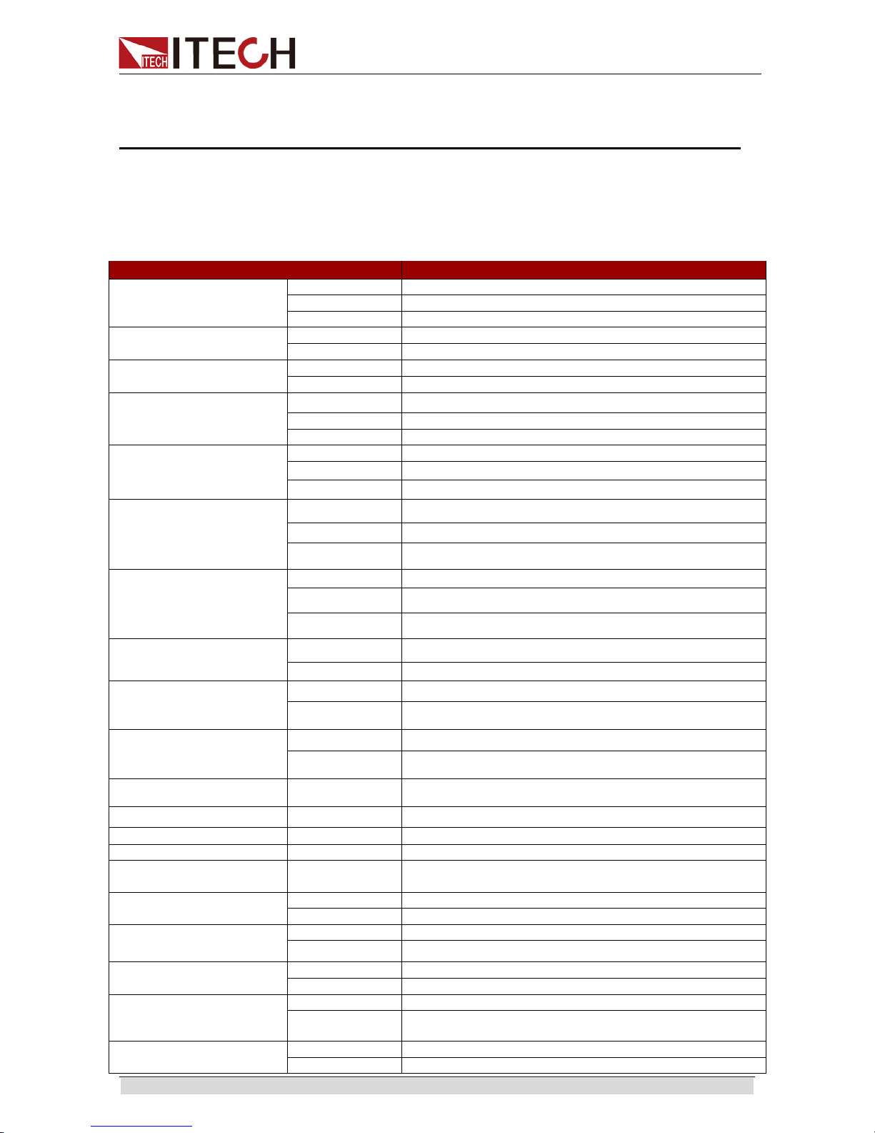
Specification
Copyright ©ITECH Electronics Co., Ltd. 42
Chapter5 Specification
This chapter will introduce the rat ed voltage, current, power and many other main
parameters of IT6500D series.
5.1 Main technical parameters
Parameter
IT6512D Version: V1.4
Output Rating
( 0 ℃ -40 ℃ )
Output Voltage
0-80V
Output Current
0-120A
Output Power
0-1800W
Line regulation
±(%of Output+Offset)
Voltage
≤0.01%+10mV
Current
≤0.01%+60mA
Load regulation
±(%of Output+Offset)
Voltage
≤0.01%+30mV
Current
≤0.05%+120mA
Setup Resolution
Voltage 10mV
Current
10mA
Power
0.1W
Read Back Resolution
Voltage
10mV
Current
10mA
Power 0.1W
Setup Accuracy1
( within 12 months, 25
℃
±5℃ )
±
(%of Output+Offset)
Voltage ≤0.05%+30mV
Current ≤0.2%+120mA
Power 1%+30W
Read Back Accuracy2
( within 12 mo nths, 25
℃
±5℃ )
±(%of Output+Offset)
Voltage ≤0.05%+30mV
Current ≤0.2%+120mA
Power 1%+30W
Ripple
(20Hz -20MHz)
Voltage ≤80mVp-p
Current ≤0.05%+60mArms
Setup Temperature
Coefficient
(%of Output/
℃
+Offset)
Voltage ≤0.01%+30mV
Current ≤0.02%+120mA
Read Back Tem peratu r e
Coefficient
(%of Output/℃ +Offset)
Voltage ≤0.01%+30mV
Current ≤0.02%+120mA
Rise time( no load ) Voltage ≤30ms
Rise time( full load ) Voltage ≤30ms
Fall time( no load )
Voltage
≤200ms
Fall time( full load )
Voltage
≤40ms
Transient Response
Time
Voltage ≤3ms
AC Input3
Voltage
220Vac±10%
Frequency
47Hz-63Hz
Setup stability-30min
( %of Output +Offset )
Voltage
≤0.05%+30mV
Current ≤0.1%+120mA
Setup stability-8h
( %of Output +Offset )
Voltage
≤0.05%+30mV
Current
≤0.1%+120mA
Readback
stability-30min
( %of Output +Offset )
Voltage
≤0.05%+30mV
Current ≤0.1%+120mA
Readback stability-8h
( %of Output +Offset )
Voltage
≤0.05%+30mV
Current
≤0.1%+120mA
Page 50

Specification
Copyright ©ITECH Electronics Co., Ltd. 43
efficiency
80%
Remote Sense
Compensation Voltage
3V
Command Response
Time
20mS
Power Factor
0.99
Maximum input current4
12A
Maximum input apparent
power
2300VA
Storage temperature
-10℃ -70℃
Protective function
OVP, OCP, OPP, OTP,Vsense reversed protect
standard Interface
USB/RS232/CAN/GPIB/LAN
Isolation ( output to
ground)
500V
Series Number
≤2
Parallel Number
≤8
Working te mperature
0-40℃
Dimensio n ( mm)
483mmW×105.4mmH×640.8mmD
Weight( net)
17Kg
Parameter
IT6522D Version: V1.4
Output Rating
( 0 ℃ -40 ℃ )
Output Voltage
0-80V
Output Current
0-120A
Output Power
0-3000W
Line regulation
±(%of Output+Offset)
Voltage
≤0.01%+10mV
Current
≤0.01%+60mA
Load regulation
±(%of Output+Offset)
Voltage
≤0.01%+30mV
Current
≤0.05%+120mA
Setup Resolution
Voltage 10mV
Current
10mA
Power
0.1W
Read Back Resolution
Voltage
10mV
Current 10mA
Power
0.1W
Setup Accuracy1
( within 12 months, 25
℃
±5℃ )
±
(%of Output+Offset)
Voltage ≤0.05%+30mV
Current ≤0.2%+120mA
Power 1% + 30W
Read Back Accuracy2
( within 12 months, 25
℃
±5℃ )
±(%of Output+Offset)
Voltage ≤0.05%+30mV
Current ≤0.2%+120mA
Power 1%+30W
Ripple
(20Hz -20MHz)
Voltage ≤80mVp-p
Current
≤0.05%+60mArms
Setup Temperature
Coefficient
(%of Output/
℃
+Offset)
Voltage ≤0.01%+30mV
Current ≤0.02%+120mA
Read Back Tem perature
Coefficient
(%of Output/℃ +Offset)
Voltage ≤0.01%+30mV
Current ≤0.02%+120mA
Rise time( no load ) Voltage ≤30ms
Rise time( full load ) Voltage ≤30ms
Fall time( no load )
Voltage
≤200ms
Fall time( full load )
Voltage
≤20ms
Transient Response
Time
Voltage ≤3ms
AC Input3
Voltage
220Vac±10%
Page 51

Specification
Copyright ©ITECH Electronics Co., Ltd. 44
Frequency
47Hz-63Hz
Setup stability-30min
( %of Output +Offset )
Voltage
≤0.05%+30mV
Current ≤0.1%+120mA
Setup stability-8h
( %of Output +Offset )
Voltage
≤0.05%+30mV
Current
≤0.1%+120mA
Readback
stability-30min
( %of Output +Offset )
Voltage
≤0.05%+30mV
Current ≤0.1%+120mA
Readback stability-8h
( %of Output +Offset )
Voltage
≤0.05%+30mV
Current
≤0.1%+120mA
efficiency
80%
Remote Sense
Compensation Voltage
3V
Command Response
Time
20mS
Power Factor
0.99
Maximum input current4 19A
Maximum input apparent
power
3800VA
Storage temperature
-10℃ -70℃
Protective function
OVP, OCP, OPP, OTP,Vsense reversed protect
standard Interface
USB/RS232/CAN/GPIB/LAN
Isolation ( output to
ground)
500V
Series Number
≤2
Parallel Number
≤8
Working te mperature
0-40℃
Dimensio n ( mm)
483mmW×105.4mmH×640.8mmD
Weight( net)
17Kg
Parameter
IT6532D Version: V1.4
Output Rating
( 0 ℃ -40 ℃ )
Output Voltage
0-80V
Output Current
0-240A
Output Power
0-6KW
Line regulation
±(%of Output+Offset)
Voltage
≤0.01%+10mV
Current
≤0.01%+120mA
Load regulation
±(%of Output+Offset)
Voltage
≤0.01%+30mV
Current
≤0.05%+240mA
Setup Resolution
Voltage 10mV
Current
100mA
Power
0.1W
Read Back Resolution
Voltage
10mV
Current 100mA
Power 0.1W
Setup Accuracy1
( within 12 months, 25
℃
±5℃ )
±(%of Output+Offset)
Voltage ≤0.05%+30mV
Current ≤0.2%+240mA
Power 1%+60W
Read Back Accuracy2
( within 12 months, 25
℃
±5℃ )
±(%of Output+Offset)
Voltage
≤0.05%+30mV
Current ≤0.2%+240mA
Power 1%+60W
Ripple
(20Hz -20MHz)
Voltage ≤80mVp-p
Current ≤0.05%+120mArms
Setup Temperature
Coefficient
Voltage ≤0.01%+30mV
Current ≤0.02%+240mA
Page 52

Specification
Copyright ©ITECH Electronics Co., Ltd. 45
(%of Output/℃ +Offset)
Read Back Tem peratu r e
Coefficient
(%of Output/℃ +Offset)
Voltage ≤0.01%+30mV
Current ≤0.02%+240mA
Rise time( no load ) Voltage ≤30ms
Rise time( full load ) Voltage ≤30ms
Fall time( no load )
Voltage
≤200ms
Fall time( full load )
Voltage
≤20ms
Transient Response
Time
Voltage ≤3ms
AC Input3
Voltage
220Vac±10%
Frequency
47Hz-63Hz
Setup stability-30min
( %of Output +Offset )
Voltage
≤0.05%+30mV
Current ≤0.1%+240mA
Setup stability-8h
( %of Output +Offset )
Voltage
≤0.05%+30mV
Current
≤0.1%+240mA
Readback
stability-30min
( %of Output +Offset )
Voltage
≤0.05%+30mV
Current ≤0.1%+240mA
Readback stability-8h
( %of Output +Offset )
Voltage
≤0.05%+30mV
Current
≤0.1%+240mA
efficiency
80%
Remote Sense
Compensation Voltage
3V
Command Response
Time
20mS
Power Factor
0.99
Maximum input current4
38A
Maximum input apparent
power
7600VA
Storage temperature
-10℃ -70℃
Protective function
OVP, OCP, OPP, OTP,Vsense reversed protect
standard Interface
USB/RS232/CAN/GPIB/LAN
Isolation ( output to
ground)
500V
Series Number
≤2
Parallel Number
≤8
Working te mperature
0-40℃
Dimensio n ( mm)
483mmW×194mmH×640.8mmD
Weight( net)
35Kg
Parameter
IT6542D Version: V1.4
Output Rating
( 0
℃
-40 ℃ )
Output Voltage
0-80V
Output Current
0-360A
Output Power
0-9KW
Line regulation
±(%of Output+Offset)
Voltage
≤0.01%+10mV
Current
≤0.01%+180mA
Load regulation
±(%of Output+Offset)
Voltage
≤0.01%+30mV
Current
≤0.05%+360mA
Setup Resolution
Voltage 10mV
Current
100mA
Power
0.1W
Read Back Resolution
Voltage
10mV
Current 100mA
Power 0.1W
Setup Accuracy1
( within 12 months, 25
℃
Voltage ≤0.05%+30mV
Current ≤0.2%+360mA
Page 53
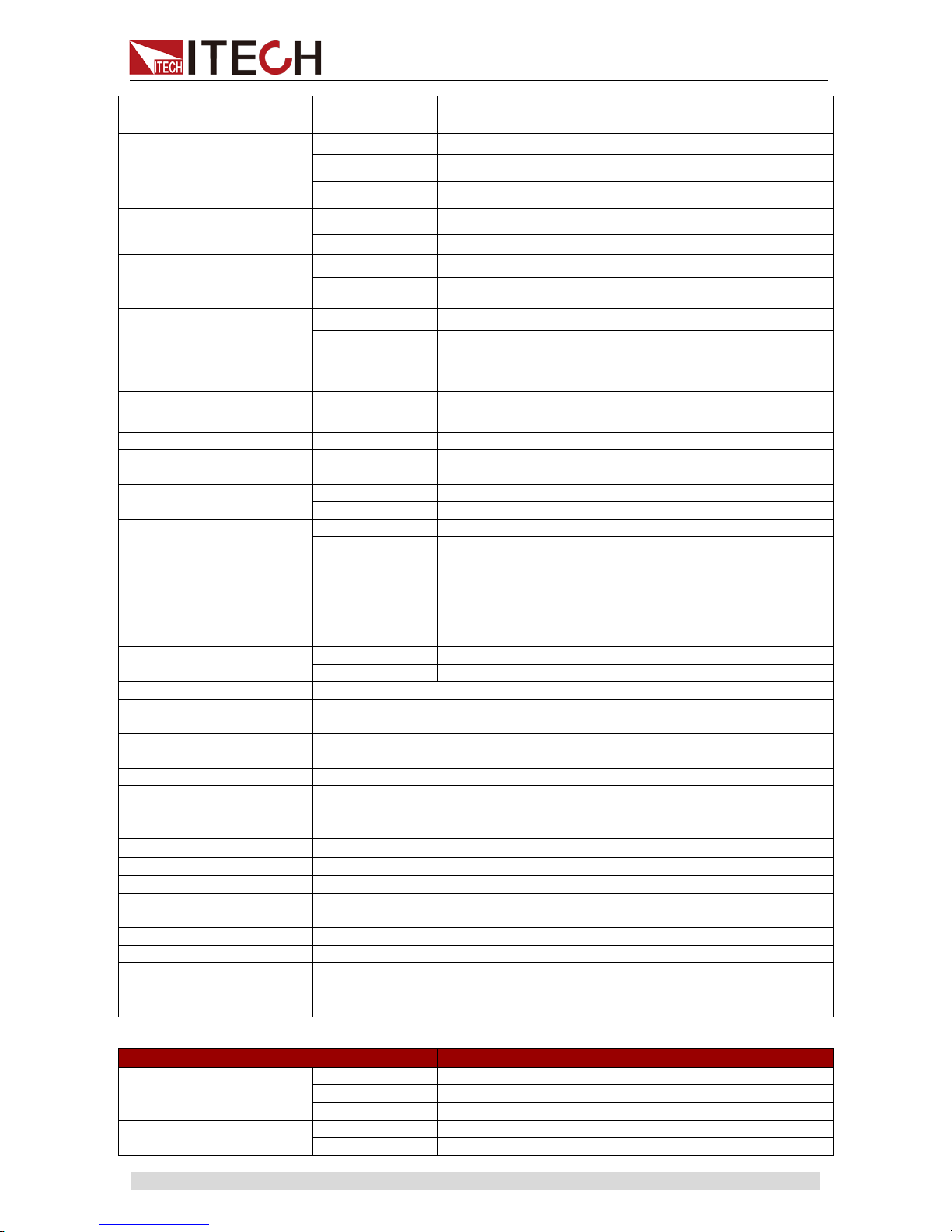
Specification
Copyright ©ITECH Electronics Co., Ltd. 46
±5℃ )
±(%of Output+Offset)
Power 1%+90W
Read Back Accuracy2
( within 12 months, 25
℃
±5℃ )
±(%of Output+Offset)
Voltage ≤0.05%+30mV
Current ≤0.2%+360mA
Power 1%+90W
Ripple
(20Hz -20MHz)
Voltage ≤80mVp-p
Current ≤0.05%+180mArms
Setup Temperature
Coefficient
(%of Output/℃ +Offset)
Voltage ≤0.01%+30mV
Current ≤0.02%+360mA
Read Back Tem peratu r e
Coefficient
(%of Output/℃ +Offset)
Voltage ≤0.01%+30mV
Current ≤0.02%+360mA
Rise time( no load ) Voltage ≤30ms
Rise time( full load ) Voltage ≤30ms
Fall time( no load )
Voltage
≤200ms
Fall time( full load )
Voltage
≤20ms
Transient Response
Time
Voltage ≤3ms
AC Input3
Voltage
220V±10%
Frequency
47Hz-63Hz
Setup stability-30min
( %of Output +Offset )
Voltage
≤0.05%+30mV
Current ≤0.1%+360mA
Setup stability-8h
( %of Output +Offset )
Voltage
≤0.05%+30mV
Current
≤0.1%+360mA
Readback
stability-30min
( %of Output +Offset )
Voltage
≤0.05%+30mV
Current ≤0.1%+360mA
Readback stability-8h
( %of Output +Offset )
Voltage
≤0.05%+30mV
Current
≤0.1%+360mA
efficiency
80%
Remote Sense
Compensation Voltage
3V
Command Response
Time
20mS
Power Factor
0.99
Maximum input current4
19A
Maximum input apparent
power
11400VA
Storage temperature
-10℃ -70℃
Protective function
OVP, OCP, OPP, OTP,Vsense reversed protect
standard Interface
USB/RS232/CAN/GPIB/LAN
Isolation ( output to
ground)
500V
Series Number
≤2
Parallel Number
≤8
Working temperature
0-40℃
Dimensio n ( mm)
483mmW×283.2mmH×640.8mmD
Weight( net)
53Kg
Parameter
IT6552D Version: V1.4
Output Rating
( 0 ℃ -40 ℃ )
Output Voltage
0-80V
Output Current
0-480A
Output Power
0-12KW
Line regulation
±(%of Output+Offset)
Voltage
≤0.01%+10mV
Current
≤0.01%+240mA
Page 54
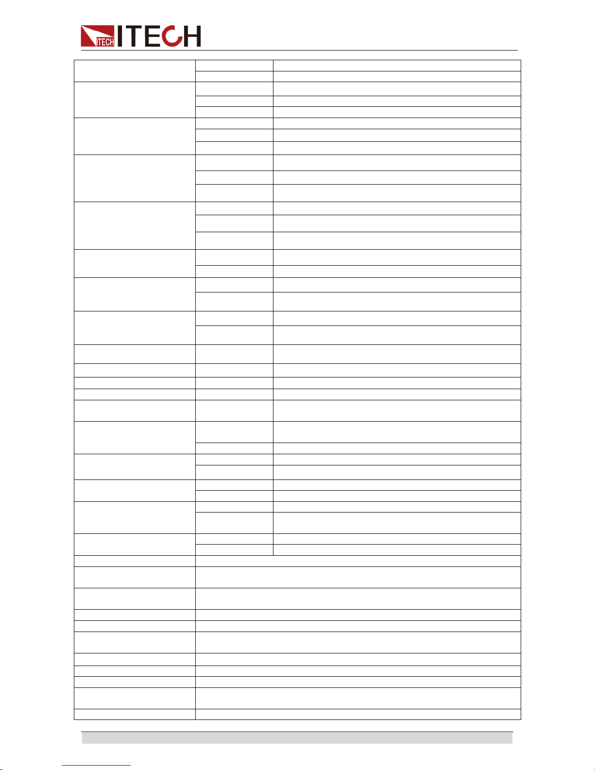
Specification
Copyright ©ITECH Electronics Co., Ltd. 47
Load regulation
±(%of Output+Offset)
Voltage
≤0.01%+30mV
Current
≤0.05%+480mA
Setup Resolution
Voltage 10mV
Current
100mA
Power
0.1W
Read Back Resolution
Voltage
10mV
Current 100mA
Power
0.1W
Setup Accuracy1
( within 12 months, 25℃
±5℃ )
±(%of Output+Offset)
Voltage ≤0.05%+30mV
Current ≤0.2%+480mA
Power 1%+120W
Read Back Accuracy2
( within 12 months, 25℃
±5℃ )
±(%of Output+Offset)
Voltage ≤0.05%+30mV
Current ≤0.2%+480mA
Power 1%+120W
Ripple
(20Hz -20MHz)
Voltage ≤80mVp-p
Current
≤0.05%+240mArms
Setup Temperature
Coefficient
(%of Output/℃ +Offset)
Voltage ≤0.01%+30mV
Current ≤0.02%+480mA
Read Back Tem peratu r e
Coefficient
(%of Output/℃ +Offset)
Voltage ≤0.01%+30mV
Current ≤0.02%+480mA
Rise time( no load ) Voltage ≤30ms
Rise time( full load ) Voltage ≤30ms
Fall time( no load )
Voltage
≤200ms
Fall time( full load )
Voltage
≤20ms
Transient Response
Time
Voltage ≤3ms
AC Input3
Voltage
380Vac±10%(Three-phase five
wires)
Frequency
47Hz-63Hz
Setup stability-30min
( %of Output +Offset )
Voltage
≤0.05%+30mV
Current ≤0.1%+480mA
Setup stability-8h
( %of Output +Offset )
Voltage
≤0.05%+30mV
Current
≤0.1%+480mA
Readback
stability-30min
( %of Output +Offset )
Voltage
≤0.05%+30mV
Current ≤0.1%+480mA
Readback stability-8h
( %of Output +Offset )
Voltage
≤0.05%+30mV
Current
≤0.1%+480mA
efficiency
80%
Remote Sense
Compensation Voltage
3V
Command Response
Time
20mS
Power Factor
0.99
Maximum input current4
38A
Maximum input apparent
power
15200VA
Storage temperature
-10℃ -70℃
Protective function
OVP, OCP, OPP, OTP,Vsense reversed protect
standard Interface
USB/RS232/CAN/GPIB/LAN
Isolation ( output to
ground)
500V
Series Number
≤2
Page 55

Specification
Copyright ©ITECH Electronics Co., Ltd. 48
Parallel Number
≤8
Working te mperature
0-40℃
Dimensio n ( mm)
554mmW×902mmH×807.5mmD( ITECH 15U Cabinet )
Weight( net)
119Kg
Parameter
IT6562D Version: V1.4
Output Rating
( 0 ℃ -40 ℃ )
Output Voltage
0-80V
Output Current
0-600A
Output Power
0-15KW
Line regulation
±(%of Output+Offset)
Voltage
≤0.01%+10mV
Current
≤0.01%+300mA
Load regulation
±(%of Output+Offset)
Voltage
≤0.01%+30mV
Current
≤0.05%+600mA
Setup Resolution
Voltage 10mV
Current
100mA
Power
0.1W
Read Back Resolution
Voltage
10mV
Current 100mA
Power
0.1W
Setup Accuracy1
( within 12 months, 25
℃
±5℃ )
±
(%of Output+Offset)
Voltage ≤0.05%+30mV
Current ≤0.2%+600mA
Power 1%+150W
Read Back Accuracy2
( within 12 months, 25
℃
±5℃ )
±(%of Output+Offset)
Voltage ≤0.05%+30mV
Current ≤0.2%+600mA
Power 1%+150W
Ripple
(20Hz -20MHz)
Voltage ≤80mVp-p
Current
≤0.05%+300mArms
Setup Temperature
Coefficient
(%of Output/
℃
+Offset)
Voltage ≤0.01%+30mV
Current ≤0.02%+600mA
Read Back Tem peratu r e
Coefficient
(%of Output/℃ +Offset)
Voltage ≤0.01%+30mV
Current ≤0.02%+600mA
Rise time( no load ) Voltage ≤30ms
Rise time( full load ) Voltage ≤30ms
Fall time( no load )
Voltage
≤200ms
Fall time( full load )
Voltage
≤20ms
Transient Response
Time
Voltage ≤3ms
AC Input3
Voltage
380Vac±10%(Three-phase five
wires)
Frequency
47Hz-63Hz
Setup stability-30min
( %of Output +Offset )
Voltage
≤0.05%+30mV
Current ≤0.1%+600mA
Setup stability-8h
( %of Output +Offset )
Voltage
≤0.05%+30mV
Current
≤0.1%+600mA
Readback
stability-30min
( %of Output +Offset )
Voltage
≤0.05%+30mV
Current ≤0.1%+600mA
Readback stability-8h
( %of Output +Offset )
Voltage
≤0.05%+30mV
Current
≤0.1%+600mA
efficiency
80%
Remote Sense
Compensation Voltage
3V
Page 56

Specification
Copyright ©ITECH Electronics Co., Ltd. 49
Command Response
Time
20mS
Power Factor
0.99
Maximum input current4
38A
Maximum input apparent
power
19000VA
Storage temperature -10℃ -70℃
Protective function
OVP, OCP, OPP, OTP,Vsense reversed protect
standard Interface
USB/RS232/CAN/GPIB/LAN
Isolation ( output to
ground)
500V
Series Number
≤2
Parallel Number
≤8
Working te mperature 0-40℃
Dimensio n ( mm)
554mmW×902mmH×807.5mmD( ITECH 15U Cabinet )
Weight( net)
137Kg
Parameter
IT6572D Version: V1.4
Output Rating
( 0 ℃ -40 ℃ )
Output Voltage
0-80V
Output Current
0-840A
Output Power
0-21KW
Line regulation
±(%of Output+Offset)
Voltage
≤0.01%+10mV
Current
≤0.01%+420mA
Load regulation
±(%of Output+Offset)
Voltage
≤0.01%+30mV
Current
≤0.05%+840mA
Setup Resolution
Voltage 10mV
Current
100mA
Power
0.1W
Read Back Resolution
Voltage
10mV
Current 100mA
Power
0.1W
Setup Accuracy1
( within 12 months, 25
℃
±5℃ )
±(%of Output+Offset)
Voltage ≤0.05%+30mV
Current ≤0.2%+840mA
Power 1%+210W
Read Back Accuracy2
( within 12 months, 25
℃
±5℃ )
±
(%of Output+Offset)
Voltage ≤0.05%+30mV
Current ≤0.2%+840mA
Power 1%+210W
Ripple
(20Hz -20MHz)
Voltage ≤80mVp-p
Current ≤0.05%+420mArms
Setup Temperature
Coefficient
(%of Output/℃ +Offset)
Voltage ≤0.01%+30mV
Current ≤0.02%+840mA
Read Back Tem peratu r e
Coefficient
(%of Output/
℃
+Offset)
Voltage ≤0.01%+30mV
Current ≤0.02%+840mA
Rise time( no load ) Voltage ≤30ms
Rise time( full load ) Voltage ≤30ms
Fall time( no load ) Voltage ≤200ms
Fall time( full load )
Voltage
≤20ms
Transient Response
Time
Voltage ≤3ms
AC Input3
Voltage
380Vac±10%(Three-phase five
wires)
Frequency
47Hz-63Hz
Setup stability-30min
Voltage
≤0.05%+30mV
Page 57
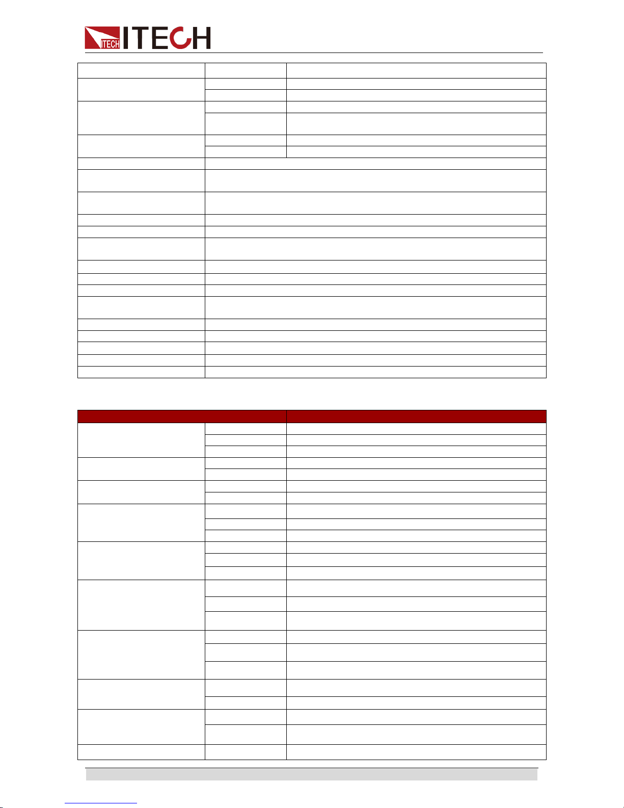
Specification
Copyright ©ITECH Electronics Co., Ltd. 50
( %of Output +Offset )
Current ≤0.1%+840mA
Setup stability-8h
( %of Output +Offset )
Voltage
≤0.05%+30mV
Current
≤0.1%+840mA
Readback
stability-30min
( %of Output +Offset )
Voltage
≤0.05%+30mV
Current ≤0.1%+840mA
Readback stability-8h
( %of Output +Offset )
Voltage
≤0.05%+30mV
Current
≤0.1%+840mA
efficiency
80%
Remote Sense
Compensation Voltage
3V
Command Response
Time
20mS
Power Factor
0.99
Maximum input current4
57A
Maximum input apparent
power
26600VA
Storage temperature
-10℃ -70℃
Protective function
OVP, OCP, OPP, OTP,Vsense reversed protect
standard Interface
USB/RS232/CAN/GPIB/LAN
Isolation ( output to
ground)
500V
Series Number
≤2
Parallel Number
≤8
Working te mperature
0-40℃
Dimensio n ( mm)
554mmW×902mmH×807.5mmD( ITECH 15U Cabinet )
Weight( net)
180Kg
Parameter
IT6582D Version: V1.4
Output Rating
( 0 ℃ -40 ℃ )
Output Voltage
0-80V
Output Current
0-960A
Output Power
0-24KW
Line regulation
±(%of Output+Offset)
Voltage
≤0.01%+10mV
Current
≤0.01%+480mA
Load regulation
±(%of Output+Offset)
Voltage
≤0.01%+30mV
Current
≤0.05%+960mA
Setup Resolution
Voltage 10mV
Current
100mA
Power
0.1W
Read Back Resolution
Voltage
10mV
Current 100mA
Power 0.1W
Setup Accuracy1
( within 12 months, 25
℃
±5℃ )
±(%of Output+Offset)
Voltage ≤0.05%+30mV
Current ≤0.2%+960mA
Power 1%+240W
Read Back Accuracy2
( within 12 months, 25
℃
±5℃ )
±(%of Output+Offset)
Voltage
≤0.05%+30mV
Current ≤0.2%+960mA
Power 1%+240W
Ripple
(20Hz -20MHz)
Voltage ≤80mVp-p
Current ≤0.05%+480mArms
Setup Temperature
Coefficient
(%of Output/℃ +Offset)
Voltage ≤0.01%+30mV
Current ≤0.02%+960mA
Read Back Tem peratu r e Voltage ≤0.01%+30mV
Page 58

Specification
Copyright ©ITECH Electronics Co., Ltd. 51
Coefficient
(%of Output/℃ +Offset)
Current ≤0.02%+960mA
Rise time( no load ) Voltage ≤30ms
Rise time( full load ) Voltage ≤30ms
Fall time( no load )
Voltage
≤200ms
Fall time( full load )
Voltage
≤20ms
Transient Response
Time
Voltage ≤3ms
AC Input3
Voltage
380Vac±10%(Three-phase five
wires)
Frequency
47Hz-63Hz
Setup stability-30min
( %of Output +Offset )
Voltage
≤0.05%+30mV
Current ≤0.1%+960mA
Setup stability-8h
( %of Output +Offset )
Voltage
≤0.05%+30mV
Current
≤0.1%+960mA
Readback
stability-30min
( %of Output +Offset )
Voltage
≤0.05%+30mV
Current ≤0.1%+960mA
Readback stability-8h
( %of Output +Offset )
Voltage
≤0.05%+30mV
Current
≤0.1%+960mA
efficiency
80%
Remote Sense
Compensation Voltage
3V
Command Response
Time
20mS
Power Factor
0.99
Maximum input current4
57A
Maximum input apparent
power
30400VA
Storage temperature
-10℃ -70℃
Protective function
OVP, OCP, OPP, OTP,Vsense reversed protect
standard Interface
USB/RS232/CAN/GPIB/LAN
Isolation ( output to
ground)
500V
Series Number
≤2
Parallel Number
≤8
Working te mperature
0-40℃
Dimensio n ( mm)
550mmW×1289.3mmH×834.8mmD
Weight( net)
248Kg
Parameter
IT6592D Version: V1.4
Output Rating
( 0
℃
-40 ℃ )
Output Voltage
0-80V
Output Curr ent
0-1200A
Output Power
0-30KW
Line regulation
±(%of Output+Offset)
Voltage
≤0.01%+10mV
Current
≤0.01%+600mA
Load regulation
±(%of Output+Offset)
Voltage
≤0.01%+30mV
Current
≤0.05%+1200mA
Setup Resolution
Voltage 10mV
Current
100mA
Power
0.1W
Read Back Resolution
Voltage
10mV
Current 100mA
Power 0.1W
Setup Accuracy1
( within 12 months, 25
℃
Voltage ≤0.05%+30mV
Current ≤0.2%+1200mA
Page 59

Specification
Copyright ©ITECH Electronics Co., Ltd. 52
±5℃ )
±(%of Output+Offset)
Power 1%+300W
Read Back Accuracy2
( within 12 months, 25
℃
±5℃ )
±(%of Output+Offset)
Voltage ≤0.05%+30mV
Current ≤0.2%+1200mA
Power 1%+300W
Ripple
(20Hz -20MHz)
Voltage ≤80mVp-p
Current ≤0.05%+600mArms
Setup Temperature
Coefficient
(%of Output/℃ +Offset)
Voltage ≤0.01%+30mV
Current ≤0.02%+1200mA
Read Back Tem perature
Coefficient
(%of Output/℃ +Offset)
Voltage ≤0.01%+30mV
Current ≤0.02%+1200mA
Rise time( no load ) Voltage ≤30ms
Rise time( full load ) Voltage ≤30ms
Fall time( no load )
Voltage
≤200ms
Fall time( full load )
Voltage
≤20ms
Transient Response
Time
Voltage ≤3ms
AC Input3
Voltage
380Vac±10%(Three-phase five
wires)
Frequency
47Hz-63Hz
Setup stability-30min
( %of Output +Offset )
Voltage
≤0.05%+30mV
Current ≤0.1%+1200mA
Setup stability-8h
( %of Output +Offset )
Voltage
≤0.05%+30mV
Current
≤0.1%+1200mA
Readback
stability-30min
( %of Output +Offset )
Voltage
≤0.05%+30mV
Current ≤0.1%+1200mA
Readback stability-8h
( %of Output +Offset )
Voltage
≤0.05%+30mV
Current
≤0.1%+1200mA
efficiency
80%
Remote Sense
Compensation Voltage
3V
Command Response
Time
20mS
Power Factor
0.99
Maximum input current4
76A
Maximum input apparent
power
38000VA
Storage temperature
-10℃ -70℃
Protective function
OVP, OCP, OPP, OTP,Vsense reversed protect
standard Interface
USB/RS232/CAN/GPIB/LAN
Isolation ( output to
ground)
500V
Series Number
≤2
Parallel Number
≤8
Working te mperature
0-40℃
Dimensio n ( mm)
550mmW×1289.3mmH×834.8mmD
Weight( net)
284Kg
Parameter IT6513D Version: V1.4
Output Rating
( 0 ℃ -40 ℃ )
Voltage
0-200V
Current
0-60A
Power
0-1800W
Line regulation
Voltage
≤0.01%+20mV
Page 60

Specification
Copyright ©ITECH Electronics Co., Ltd. 53
±(%of Output+Offset)
Current ≤0.01%+30mA
Load regulation
±(%of Output+Offset)
Voltage
≤0.01%+50mV
Current
≤0.05%+60mA
Setup Resolution
Voltage 10mV
Current
10mA
Power
0.1W
Read Back Resolution
Voltage
10mV
Current 10mA
Power 0.1W
Setup Accuracy1
( within 12 months, 25
℃
±5℃ )
±
(%of Output+Offset)
Voltage ≤0.05%+100mV
Current ≤0.2%+60mA
Power ≤1%+30W
Read Back Accuracy2
( within 12 months, 25
℃
±5℃ )
±
(%of Output+Offset)
Voltage ≤0.05%+100mV
Current ≤0.2%+60mA
Power ≤1%+30W
Ripple
(20Hz -20MHz)
Voltage ≤200mVp-p
Current
≤50mArms
Setup Temperature
Coefficient
(%of Output/℃ +Offset)
Voltage ≤0.05%+100mV
Current ≤0.2%+60mA
Read Back Tem peratu r e
Coefficient
(%of Output/
℃
+Offset)
Voltage ≤0.05%+100mV
Current ≤0.2%+60mA
Rise time( no load ) Voltage ≤100ms
Rise time( full load ) Voltage ≤100ms
Fall time( no load )
Voltage
≤200ms
Fall time( full load )
Voltage
≤40ms
Transient Response
Time
≤2ms
AC Input3
Voltage
220V±10%
Frequenc
y
47Hz-63Hz
Setup
stability-30min
( %of Output +Offset )
Voltage
≤0.05%+100mV
Current ≤0.2%+60mA
Setup stability-8h
( %of Output +Offset )
Voltage
≤0.05%+100mV
Current
≤0.2%+60mA
Readback
stability-30min
( %of Output +Offset )
Voltage
≤0.05%+100mV
Current ≤0.2%+60mA
Readback stability-8h
( %of Output +Offset )
Voltage
≤0.05%+100mV
Current
≤0.2%+60mA
efficiency
89%(30V/60A)-90.5%(200V/9A)
Remote Sense
Compensation Voltage
2V
Command Response
Time
20mS
Power Factor
0.99
Maximum input current4
10A
Maximum input
apparent power
2100VA
Storage temperature -10℃ -70℃
Protective function
OVP, OCP, OPP, OTP, Vsense reversed protect
standard Interface
USB/RS232/CAN/GPIB/LAN
Page 61

Specification
Copyright ©ITECH Electronics Co., Ltd. 54
Isolation ( output to
ground)
500V
Series Number
≤2
Parallel Number
≤8
Working te mperature 0-40℃
Dimensio n ( mm)
483mmW×105.4mmH×640.8mmD
Weight( net)
17Kg
Parameter
IT6523D Version: V1.4
Output Rating
( 0 ℃ -40 ℃ )
Voltage
0-200V
Current
0-60A
Power
0-3000W
Line regulation
±
(%of Output+Offset)
Voltage
≤0.01%+20mV
Current
≤0.01%+30mA
Load regulation
±(%of Output+Offset)
Voltage
≤0.01%+50mV
Current
≤0.05%+60mA
Setup Resolution
Voltage 10mV
Current
10mA
Power
0.1W
Read Back Resolution
Voltage
10mV
Current 10mA
Power
0.1W
Setup Accuracy1
( within 12 months, 25
℃
±5℃ )
±
(%of Output+Offset)
Voltage ≤0.05%+100mV
Current ≤0.2%+60mA
Power ≤1%+30W
Read Back Accuracy2
( within 12 months, 25
℃
±5℃ )
±
(%of Output+Offset)
Voltage ≤0.05%+100mV
Current ≤0.2%+60mA
Power ≤1%+30W
Ripple
(20Hz -20MHz)
Voltage ≤200mVp-p
Current ≤50mArms
Setup Temperature
Coefficient
(%of Output/℃ +Offset)
Voltage ≤0.05%+100mV
Current ≤0.2%+60mA
Read Back Tem peratu r e
Coefficient
(%of Output/℃ +Offset)
Voltage ≤0.05%+100mV
Current ≤0.2%+60mA
Rise time( no load ) Voltage ≤100ms
Rise time( full load ) Voltage ≤100ms
Fall time( no load )
Voltage
≤200ms
Fall time( full load )
Voltage
≤20ms
Transient Response
Time
≤2ms
AC Input3
Voltage
220V±10%
Frequenc
y
47Hz-63Hz
Setup
stability-30min
( %of Output +Offset )
Voltage
≤0.05%+100mV
Current ≤0.2%+60mA
Setup stability-8h
( %of Output +Offset )
Voltage
≤0.05%+100mV
Current
≤0.2%+60mA
Readback
stability-30min
( %of Output +Offset )
Voltage
≤0.05%+100mV
Current ≤0.2%+60mA
Page 62

Specification
Copyright ©ITECH Electronics Co., Ltd. 55
Readback stability-8h
( %of Output +Offset )
Voltage
≤0.05%+100mV
Current
≤0.2%+60mA
efficiency
89%(50V/60A)-90.5%(200V/15A)
Remote Sense
Compensation Voltage
2V
Command Response
Time
20mS
Power Factor
0.99
Maximum input current4 19A
Maximum input
apparent power
3800VA
Storage temperature
-10℃ -70℃
Protective function
OVP, OCP, OPP, OTP, Vsense reversed protect
standard Interface
USB/RS232/CAN/GPIB/LAN
Isolation ( output to
ground)
500V
Series Number
≤2
Parallel Number
≤8
Working te mperature
0-40℃
Dimensio n ( mm)
483mmW×105.4mmH×640.8mmD
Weight( net)
17Kg
Parameter
IT6533D Version: V1.4
Output Rating
( 0 ℃ -40 ℃ )
Voltage
0-200V
Current
0-120A
Power
0-6KW
Line regulation
±(%of Output+Offset)
Voltage ≤0.01%+20mV
Current
≤0.01%+60mA
Load regulation
±(%of Output+Offset)
Voltage
≤0.01%+50mV
Current
≤0.05%+120mA
Setup Resolution
Voltage 10mV
Current
10mA
Power
0.1W
Read Back Resolution
Voltage
10mV
Current 10mA
Power
0.1W
Setup Accuracy1
( within 12 months, 25
℃
±5℃ )
±
(%of Output+Offset)
Voltage ≤0.05%+100mV
Current ≤0.2%+120mA
Power ≤1%+60W
Read Back Accuracy2
( within 12 months, 25
℃
±5℃ )
±
(%of Output+Offset)
Voltage ≤0.05%+100mV
Current ≤0.2%+120mA
Power ≤1%+60W
Ripple
(20Hz -20MHz)
Voltage ≤200mVp-p
Current ≤100mArms
Setup Temperature
Coefficient
(%of Output/℃ +Offset)
Voltage ≤0.05%+100mV
Current ≤0.2%+120mA
Read Back Tem peratu r e
Coefficient
(%of Output/℃ +Offset)
Voltage ≤0.05%+100mV
Current ≤0.2%+120mA
Rise time( no load ) Voltage ≤100ms
Rise time( full load ) Voltage ≤100ms
Page 63

Specification
Copyright ©ITECH Electronics Co., Ltd. 56
Fall time( no load )
Voltage
≤200ms
Fall time( full load )
Voltage
≤20ms
Transient Response
Time
≤2ms
AC Input3
Voltage
220V±10%
Frequenc
y
47Hz-63Hz
Setup
stability-30min
( %of Output +Offset )
Voltage
≤0.05%+100mV
Current ≤0.2%+120mA
Setup stability-8h
( %of Output +Offset )
Voltage
≤0.05%+100mV
Current
≤0.2%+120mA
Readback
stability-30min
( %of Output +Offset )
Voltage
≤0.05%+100mV
Current ≤0.2%+120mA
Readback stability-8h
( %of Output +Offset )
Voltage
≤0.05%+100mV
Current
≤0.2%+120mA
efficiency
89%(50V/120A)-90.5%(200V/30A)
Remote Sense
Compensation Voltage
2V
Command Response
Time
20mS
Power Factor
0.99
Maximum input current4
38A
Maximum input
apparent power
7600VA
Storage temperature
-10℃ -70℃
Protective function
OVP, OCP, OPP, OTP, Vsense reversed protect
standard Interface
USB/RS232/CAN/GPIB/LAN
Isolation ( output to
ground)
500V
Series Number
≤2
Parallel Number
≤8
Working te mperature
0-40℃
Dimensio n ( mm)
483mmW×194mmH×640.8mmD
Weight( net)
35Kg
Parameter
IT6543D Version: V1.4
Output Rating
( 0 ℃ -40 ℃ )
Voltage
0-200V
Current
0-180A
Power
0-9KW
Line regulation
±(%of Output+Offset)
Voltage ≤0.01%+20mV
Current
≤0.01%+90mA
Load regulation
±(%of Output+Offset)
Voltage
≤0.01%+50mV
Current
≤0.05%+180mA
Setup Resolution
Voltage 10mV
Current
10mA
Power
0.1W
Read Back Resolution
Voltage
10mV
Current
10mA
Power 0.1W
Setup Accuracy1
( within 12 months, 25
℃
±5℃ )
±
(%of Output+Offset)
Voltage ≤0.05%+100mV
Current ≤0.2%+180mA
Power ≤1%+90W
Read Back Accuracy2
Voltage ≤0.05%+100mV
Page 64

Specification
Copyright ©ITECH Electronics Co., Ltd. 57
( within 12 months, 25
℃
±5℃ )
±(%of Output+Offset)
Current ≤0.2%+180mA
Power ≤1%+90W
Ripple
(20Hz -20MHz)
Voltage ≤200mVp-p
Current ≤150mArms
Setup Temperature
Coefficient
(%of Output/℃ +Offset)
Voltage ≤0.05%+100mV
Current ≤0.2%+180mA
Read Back Tem peratu r e
Coefficient
(%of Output/℃ +Offset)
Voltage ≤0.05%+100mV
Current ≤0.2%+180mA
Rise time( no load ) Voltage ≤100ms
Rise time( full load ) Voltage ≤100ms
Fall time( no load )
Voltage
≤200ms
Fall time( full load )
Voltage
≤20ms
Transient Response
Time
≤2ms
AC Input3
Voltage
220V±10%
Frequenc
y
47Hz-63Hz
Setup
stability-30min
( %of Output +Offset )
Voltage
≤0.05%+100mV
Current ≤0.2%+180mA
Setup stability-8h
( %of Output +Offset )
Voltage
≤0.05%+100mV
Current
≤0.2%+180mA
Readback
stability-30min
( %of Output +Offset )
Voltage
≤0.05%+100mV
Current ≤0.2%+180mA
Readback stability-8h
( %of Output +Offset )
Voltage
≤0.05%+100mV
Current
≤0.2%+180mA
efficiency
89%(50V/180A)-90.5%(200V/45A)
Remote Sense
Compensation Voltage
2V
Command Response
Time
20mS
Power Factor
0.99
Maximum input current4
19A
Maximum input
apparent power
11400VA
Storage temperature
-10℃ -70℃
Protective function
OVP, OCP, OPP, OTP, Vsense reversed protect
standard Interface
USB/RS232/CAN/GPIB/LAN
Isolation ( output to
ground)
500V
Series Number
≤2
Parallel Number
≤8
Working temperature
0-40℃
Dimensio n ( mm)
483mmW×283.2mmH×640.8mmD
Weight( net)
53Kg
Parameter
IT6553D Version: V1.4
Output Rating
( 0 ℃ -40 ℃ )
Voltage
0-200V
Current
0-240A
Power
0-12KW
Line regulation
±
(%of Output+Offset)
Voltage
≤0.01%+20mV
Current
≤0.01%+120mA
Load regulation
Voltage
≤0.01%+50mV
Page 65
Specification
Copyright ©ITECH Electronics Co., Ltd. 58
±(%of Output+Offset)
Current ≤0.05%+240mA
Setup Resolution
Voltage 10mV
Current
100mA
Power
0.1W
Read Back Resolution
Voltage
10mV
Current 100mA
Power 0.1W
Setup Accuracy1
( within 12 months, 25
℃
±5℃ )
±
(%of Output+Offset)
Voltage ≤0.05%+100mV
Current ≤0.2%+240mA
Power ≤1%+120W
Read Back Accuracy2
( within 12 months, 25
℃
±5℃ )
±
(%of Output+Offset)
Voltage ≤0.05%+100mV
Current ≤0.2%+240mA
Power ≤1%+120W
Ripple
(20Hz -20MHz)
Voltage ≤200mVp-p
Current ≤200mArms
Setup Temperature
Coefficient
(%of Output/
℃
+Offset)
Voltage ≤0.05%+100mV
Current ≤0.2%+240mA
Read Back Tem peratu r e
Coefficient
(%of Output/
℃
+Offset)
Voltage ≤0.05%+100mV
Current ≤0.2%+240mA
Rise time( no load ) Voltage ≤100ms
Rise time( full load ) Voltage ≤100ms
Fall time( no load )
Voltage
≤200ms
Fall time( full load )
Voltage
≤20ms
Transient Response
Time
≤2ms
AC Input3
Voltage
380Vac±10%(Three-phase five
wires)
Frequenc
y
47Hz-63Hz
Setup
stability-30min
( %of Output +Offset )
Voltage
≤0.05%+100mV
Current ≤0.2%+240mA
Setup stability-8h
( %of Output +Offset )
Voltage
≤0.05%+100mV
Current
≤0.2%+240mA
Readback
stability-30min
( %of Output +Offset )
Voltage
≤0.05%+100mV
Current ≤0.2%+240mA
Readback stability-8h
( %of Output +Offset )
Voltage
≤0.05%+100mV
Current
≤0.2%+240mA
efficiency
89%(50V/240A)-90.5%(200V/60A)
Remote Sense
Compensation Voltage
2V
Command Response
Time
20mS
Power Factor
0.99
Maximum input current4
38A
Maximum input
apparent power
15200VA
Storage temperature
-10℃ -70℃
Protective function
OVP, OCP, OPP, OTP, Vsense reversed protect
standard Interface
USB/RS232/CAN/GPIB/LAN
Isolation ( output to
500V
Page 66

Specification
Copyright ©ITECH Electronics Co., Ltd. 59
ground)
Series Number
≤2
Parallel Number
≤8
Working te mperature
0-40℃
Dimensio n ( mm)
554mmW×902mmH×807.5mmD( ITECH 15U Cabinet )
Weight( net)
119Kg
Parameter
IT6563D Version: V1.4
Output Rating
( 0 ℃ -40 ℃ )
Voltage
0-200V
Current
0-300A
Power
0-15KW
Line regulation
±(%of Output+Offset)
Voltage
≤0.01%+20mV
Current
≤0.01%+150mA
Load regulation
±(%of Output+Offset)
Voltage
≤0.01%+50mV
Current
≤0.05%+300mA
Setup Resolution
Voltage 10mV
Current
100mA
Power
0.1W
Read Back Resolution
Voltage
10mV
Current 100mA
Power 0.1W
Setup Accuracy1
( within 12 months, 25
℃
±5℃ )
±
(%of Output+Offset)
Voltage ≤0.05%+100mV
Current ≤0.2%+300mA
Power ≤1%+150W
Read Back Accuracy2
( within 12 months, 25
℃
±5℃ )
±
(%of Output+Offset)
Voltage ≤0.05%+100mV
Current ≤0.2%+300mA
Power ≤1%+150W
Ripple
(20Hz -20MHz)
Voltage ≤200mVp-p
Current ≤250mArms
Setup Temperature
Coefficient
(%of Output/
℃
+Offset)
Voltage ≤0.05%+100mV
Current ≤0.2%+300mA
Read Back Tem peratu r e
Coefficient
(%of Output/℃ +Offset)
Voltage ≤0.05%+100mV
Current ≤0.2%+300mA
Rise time( no load ) Voltage ≤100ms
Rise time( full load ) Voltage ≤100ms
Fall time( no load )
Voltage
≤200ms
Fall time( full load )
Voltage
≤20ms
Transient Response
Time
≤2ms
AC Input3
Voltage
380Vac±10%(Three-phase five wires)
Frequenc
y
47Hz-63Hz
Setup
stability-30min
( %of Output +Offset )
Voltage
≤0.05%+100mV
Current ≤0.2%+300mA
Setup stability-8h
( %of Output +Offset )
Voltage
≤0.05%+100mV
Current
≤0.2%+300mA
Readback
stability-30min
( %of Output +Offset )
Voltage
≤0.05%+100mV
Current ≤0.2%+300mA
Readback stability-8h
Voltage
≤0.05%+100mV
Page 67

Specification
Copyright ©ITECH Electronics Co., Ltd. 60
( %of Output +Offset )
Current
≤0.2%+300mA
efficiency
89%(50V/300A)-90.5%(200V/75A)
Remote Sense
Compensation Voltage
2V
Command Response
Time
20mS
Power Factor
0.99
Maximum input current4
38A
Maximum input
apparent power
19000VA
Storage temperature
-10℃ -70℃
Protective function
OVP, OCP, OPP, OTP, Vsense reversed protect
standard Interface
USB/RS232/CAN/GPIB/LAN
Isolation ( output to
ground)
500V
Series Number
≤2
Parallel Number
≤8
Working te mperature
0-40℃
Dimensio n ( mm)
554mmW×902mmH×807.5mmD( ITECH 15U Cabinet )
Weight( net)
137Kg
Parameter
IT6573D Version: V1.4
Output Rating
( 0 ℃ -40 ℃ )
Voltage
0-200V
Current
0-420A
Power
0-21KW
Line regulation
±(%of Output+Offset)
Voltage
≤0.01%+20mV
Current
≤0.01%+210mA
Load regulation
±(%of Output+Offset)
Voltage
≤0.01%+50mV
Current
≤0.05%+420mA
Setup Resolution
Voltage 10mV
Current
100mA
Power
0.1W
Read Back Resolution
Voltage
10mV
Current 100mA
Power 0.1W
Setup Accuracy1
( within 12 months, 25
℃
±5℃ )
±
(%of Output+Offset)
Voltage ≤0.05%+100mV
Current ≤0.2%+420mA
Power ≤1%+210W
Read Back Accuracy2
( within 12 months, 25
℃
±5℃ )
±
(%of Output+Offset)
Voltage ≤0.05%+100mV
Current ≤0.2%+420mA
Power ≤1%+210W
Ripple
(20Hz -20MHz)
Voltage ≤200mVp-p
Current
≤350mArms
Setup Temperature
Coefficient
(%of Output/
℃
+Offset)
Voltage ≤0.05%+100mV
Current ≤0.2%+420mA
Read Back Tem peratu r e
Coefficient
(%of Output/℃ +Offset)
Voltage ≤0.05%+100mV
Current ≤0.2%+420mA
Rise time( no load ) Voltage ≤100ms
Rise time( full load ) Voltage ≤100ms
Fall time( no load )
Voltage
≤200ms
Fall time( full load )
Voltage
≤20ms
Page 68

Specification
Copyright ©ITECH Electronics Co., Ltd. 61
Transient Response
Time
≤2ms
AC Input3
Voltage
380V±10%(Three-phase five wires)
Frequenc
y
47Hz-63Hz
Setup
stability-30min
( %of Output +Offset )
Voltage
≤0.05%+100mV
Current ≤0.2%+420mA
Setup stability-8h
( %of Output +Offset )
Voltage
≤0.05%+100mV
Current
≤0.2%+420mA
Readback
stability-30min
( %of Output +Offset )
Voltage
≤0.05%+100mV
Current ≤0.2%+420mA
Readback stability-8h
( %of Output +Offset )
Voltage
≤0.05%+100mV
Current
≤0.2%+420mA
efficiency
89%(50V/420A)-90.5%(200V/105A)
Remote Sense
Compensation Voltage
2V
Command Response
Time
20mS
Power Factor
0.99
Maximum input current4 57A
Maximum input
apparent power
26600VA
Storage temperature
-10℃ -70℃
Protective function
OVP, OCP, OPP, OTP, Vsense reversed protect
standard Interface
USB/RS232/CAN/GPIB/LAN
Isolation ( output to
ground)
500V
Series Number
≤2
Parallel Number
≤8
Working te mperature
0-40℃
Dimensio n ( mm)
554mmW×902mmH×807.5mmD( ITECH 15U Cabinet )
Weight( net)
180Kg
Parameter
IT6583D Version: V1.4
Output Rating
( 0
℃
-40 ℃ )
Voltage
0-200V
Current
0-480A
Power
0-24KW
Line regulation
±(%of Output+Offset)
Voltage
≤0.01%+20mV
Current
≤0.01%+240mA
Load regulation
±(%of Output+Offset)
Voltage
≤0.01%+50mV
Current
≤0.05%+480mA
Setup Resolution
Voltage 10mV
Current
100mA
Power
0.1W
Read Back Resolution
Voltage
10mV
Current 100mA
Power 0.1W
Setup Accuracy1
( within 12 months, 25
℃
±5℃ )
±
(%of Output+Offset)
Voltage ≤0.05%+100mV
Current ≤0.2%+480mA
Power ≤1%+240W
Read Back Accuracy2
( within 12 months, 25
℃
±5℃ )
±
(%of Output+Offset)
Voltage ≤0.05%+100mV
Current ≤0.2%+480mA
Power ≤1%+240W
Page 69

Specification
Copyright ©ITECH Electronics Co., Ltd. 62
Ripple
(20Hz -20MHz)
Voltage ≤200mVp-p
Current
≤400mArms
Setup Temperature
Coefficient
(%of Output/℃ +Offset)
Voltage ≤0.05%+100mV
Current ≤0.2%+480mA
Read Back Tem peratu r e
Coefficient
(%of Output/℃ +Offset)
Voltage ≤0.05%+100mV
Current ≤0.2%+480mA
Rise time( no load ) Voltage ≤100ms
Rise time( full load ) Voltage ≤100ms
Fall time( no load )
Voltage
≤200ms
Fall time( full load )
Voltage
≤20ms
Transient Response
Time
≤2ms
AC Input3
Voltage
380V±10%(Three-phase five wires)
Frequenc
y
47Hz-63Hz
Setup
stability-30min
( %of Output +Offset )
Voltage
≤0.05%+100mV
Current ≤0.2%+480mA
Setup stability-8h
( %of Output +Offset )
Voltage
≤0.05%+100mV
Current
≤0.2%+480mA
Readback
stability-30min
( %of Output +Offset )
Voltage
≤0.05%+100mV
Current ≤0.2%+480mA
Readback stability-8h
( %of Output +Offset )
Voltage
≤0.05%+100mV
Current
≤0.2%+480mA
efficiency
89%(50V/480A)-90.5%(200V/120A)
Remote Sense
Compensation Voltage
2V
Command Response
Time
20mS
Power Factor
0.99
Maximum input current4
57A
Maximum input
apparent power
30400VA
Storage temperature
-10℃ -70℃
Protective function
OVP, OCP, OPP, OTP, Vsense reversed protect
standard Interface
USB/RS232/CAN/GPIB/LAN
Isolation ( output to
ground)
500V
Series Number
≤2
Parallel Number
≤8
Working te mperature
0-40℃
Dimensio n ( mm)
550mmW×1289.3mmH×834.8mmD
Weight( net)
248Kg
Parameter
IT6593D Version: V1.4
Output Rating
( 0
℃
-40 ℃ )
Voltage
0-200V
Current
0-600A
Power
0-30KW
Line regulation
±(%of Output+Offset)
Voltage ≤0.01%+20mV
Current
≤0.01%+300mA
Load regulation
±(%of Output+Offset)
Voltage
≤0.01%+50mV
Current
≤0.05%+600mA
Setup Resolution
Voltage 10mV
Current
100mA
Page 70

Specification
Copyright ©ITECH Electronics Co., Ltd. 63
Power
0.1W
Read Back Resolution
Voltage
10mV
Current 100mA
Power
0.1W
Setup Accuracy1
( within 12 months, 25
℃
±5℃ )
±
(%of Output+Offset)
Voltage ≤0.05%+100mV
Current ≤0.2%+600mA
Power ≤1%+300W
Read Back Accuracy2
( within 12 months, 25
℃
±5℃ )
±
(%of Output+Offset)
Voltage ≤0.05%+100mV
Current ≤0.2%+600mA
Power ≤1%+300W
Ripple
(20Hz -20MHz)
Voltage ≤200mVp-p
Current
≤500mArms
Setup Temperature
Coefficient
(%of Output/℃ +Offset)
Voltage ≤0.05%+100mV
Current ≤0.2%+600mA
Read Back Tem peratu r e
Coefficient
(%of Output/℃ +Offset)
Voltage ≤0.05%+100mV
Current ≤0.2%+600mA
Rise time( no load ) Voltage ≤100ms
Rise time( full load ) Voltage ≤100ms
Fall time( no load )
Voltage
≤200ms
Fall time( full load )
Voltage
≤20ms
Transient Response
Time
≤2ms
AC Input3
Voltage
380V±10%(Three-phase five wires)
Frequenc
y
47Hz-63Hz
Setup
stability-30min
( %of Output +Offset )
Voltage
≤0.05%+100mV
Current ≤0.2%+600mA
Setup stability-8h
( %of Output +Offset )
Voltage
≤0.05%+100mV
Current
≤0.2%+600mA
Readback
stability-30min
( %of Output +Offset )
Voltage
≤0.05%+100mV
Current ≤0.2%+600mA
Readback stability-8h
( %of Output +Offset )
Voltage
≤0.05%+100mV
Current
≤0.2%+600mA
efficiency
89%(50V/600A)-90.5%(200V/150A)
Remote Sense
Compensation Voltage
2V
Command Response
Time
20mS
Power Factor
0.99
Maximum input current4
76A
Maximum input
apparent power
38000VA
Storage temperature
-10℃ -70℃
Protective function
OVP, OCP, OPP, OTP, Vsense reversed protect
standard Interface
USB/RS232/CAN/GPIB/LAN
Isolation ( output to
ground)
500V
Series Number
≤2
Parallel Number
≤8
Working te mperature
0-40℃
Page 71

Specification
Copyright ©ITECH Electronics Co., Ltd. 64
Dimensio n ( mm)
550mmW×1289.3mmH×834.8mmD
Weight( net)
284Kg
Parameter IT6514D Version: V1.4
Output Rating
( 0 ℃ -40 ℃ )
Output Voltage
0-360V
Output Current
0-30A
Output Power
0-1800W
Line regulation
±(%of Output+Offset)
Voltage
≤0.01%+40mV
Current
≤0.01%+15mA
Load regulation
±(%of Output+Offset)
Voltage
≤0.01%+135mV
Current
≤0.05%+30mA
Setup Resolution
Voltage 10mV
Current
10mA
Power
0.1W
Read Back Resolution
Voltage
10mV
Current 10mA
Power 0.1W
Setup Accuracy1
( within 12 months, 25
℃
±5℃ )
±
(%of Output+Offset)
Voltage ≤0.05%+135mV
Current ≤0.2%+30mA
Power 1%+30W
Read Back Accuracy2
( within 12 months, 25
℃
±5℃ )
±(%of Output+Offset)
Voltage ≤0.05%+135mV
Current ≤0.2%+30mA
Power 1%+30W
Ripple
(20Hz -20MHz)
Voltage ≤360mVp-p
Current ≤0.05%+30mArms
Setup Temperature
Coefficient
(%of Output/℃ +Offset)
Voltage ≤0.01%+135mV
Current ≤0.02%+30mA
Read Back Tem peratu r e
Coefficient
(%of Output/℃ +Offset)
Voltage ≤0.01%+135mV
Current ≤0.02%+30mA
Rise time( no load ) Voltage ≤250ms
Rise time( full load ) Voltage ≤250ms
Fall time( no load )
Voltage
≤850ms
Fall time( full load )
Voltage
≤140ms
Transient Response
Time
Voltage ≤3ms
AC Input3
Voltage
220Vac±10%
Frequency
47Hz-63Hz
Setup stability-30min
( %of Output +Offset )
Voltage
≤0.05%+135mV
Current ≤0.1%+30mA
Setup stability-8h
( %of Output +Offset )
Voltage
≤0.05%+135mV
Current
≤0.1%+30mA
Readback
stability-30min
( %of Output +Offset )
Voltage
≤0.05%+135mV
Current ≤0.1%+30mA
Readback stability-8h
( %of Output +Offset )
Voltage
≤0.05%+135mV
Current
≤0.1%+30mA
efficiency
80%
Remote Sense
Compensation Voltage
3V
Command Response
Time
20mS
Power Factor
0.99
Page 72

Specification
Copyright ©ITECH Electronics Co., Ltd. 65
Maximum input current4
12A
Maximum input apparent
power
2300VA
Storage temperature
-10℃ -70℃
Protective function
OVP, OCP, OPP, OTP,Vsense reversed protect
standard Interface
USB/RS232/CAN/GPIB/LAN
Isolation ( output to
ground)
500V
Parallel Number
≤8
Working te mperature
0-40℃
Dimensio n ( mm)
483mmW×105.4mmH×640.8mmD
Weight( net)
17Kg
Parameter
IT6524D Version: V1.4
Output Rating
( 0 ℃ -40 ℃ )
Output Voltage
0-360V
Output Current
0-30A
Output Power
0-3000W
Line regulation
±(%of Output+Offset)
Voltage
≤0.01%+40mV
Current
≤0.01%+15mA
Load regulation
±(%of Output+Offset)
Voltage
≤0.01%+135mV
Current
≤0.05%+30mA
Setup Resolution
Voltage 10mV
Current
10mA
Power
0.1W
Read Back Resolution
Voltage
10mV
Current
10mA
Power
0.1W
Setup Accuracy1
( within 12 months, 25
℃
±5℃ )
±
(%of Output+Offset)
Voltage ≤0.05%+135mV
Current ≤0.2%+30mA
Power 1%+30W
Read Back Accuracy2
( within 12 months, 25
℃
±5℃ )
±(%of Output+Offset)
Voltage ≤0.05%+135mV
Current ≤0.2%+30mA
Power 1%+30W
Ripple
(20Hz -20MHz)
Voltage ≤360mVp-p
Current
≤0.05%+30mArms
Setup Temperature
Coefficient
(%of Output/
℃
+Offset)
Voltage ≤0.01%+135mV
Current ≤0.02%+30mA
Read Back Tem peratu r e
Coefficient
(%of Output/℃ +Offset)
Voltage ≤0.01%+135mV
Current ≤0.02%+30mA
Rise time( no load ) Voltage ≤250ms
Rise time( full load ) Voltage ≤250ms
Fall time( no load )
Voltage
≤850ms
Fall time( full load )
Voltage
≤70ms
Transient Response
Time
Voltage ≤3ms
AC Input3
Voltage
220Vac±10%
Frequency
47Hz-63Hz
Setup stability-30min
( %of Output +Offset )
Voltage
≤0.05%+135mV
Current ≤0.1%+30mA
Setup stability-8h
( %of Output +Offset )
Voltage
≤0.05%+135mV
Current
≤0.1%+30mA
Readback
Voltage
≤0.05%+135mV
Page 73
Specification
Copyright ©ITECH Electronics Co., Ltd. 66
stability-30min
( %of Output +Offset )
Current ≤0.1%+30mA
Readback stability-8h
( %of Output +Offset )
Voltage
≤0.05%+135mV
Current
≤0.1%+30mA
efficiency
80%
Remote Sense
Compensation Voltage
3V
Command Response
Time
20mS
Power Factor
0.99
Maximum input current4
19A
Maximum input apparent
power
3800VA
Storage temperature -10℃ -70℃
Protective function
OVP, OCP, OPP, OTP,Vsense reversed protect
standard Interface
USB/RS232/CAN/GPIB/LAN
Isolation ( output to
ground)
500V
Parallel Number
≤8
Working te mperature 0-40℃
Dimensio n ( mm)
483mmW×105.4mmH×640.8mmD
Weight( net)
17Kg
Parameter
IT6534D Version: V1.4
Output Rating
( 0
℃
-40 ℃ )
Output Voltage
0-360V
Output Current
0-60A
Output Power
0-6KW
Line regulation
±(%of Output+Offset)
Voltage
≤0.01%+40mV
Current
≤0.01%+30mA
Load regulation
±(%of Output+Offset)
Voltage
≤0.01%+135mV
Current
≤0.05%+60mA
Setup Resolution
Voltage 10mV
Current
10mA
Power
0.1W
Read Back Resolution
Voltage
10mV
Current 10mA
Power
0.1W
Setup Accuracy1
( within 12 months, 25
℃
±5℃ )
±(%of Output+Offset)
Voltage ≤0.05%+135mV
Current ≤0.2%+60mA
Power 1%+60W
Read Back Accuracy2
( within 12 months, 25
℃
±5℃ )
±
(%of Output+Offset)
Voltage ≤0.05%+135mV
Current ≤0.2%+60mA
Power 1%+60W
Ripple
(20Hz -20MHz)
Voltage ≤360mVp-p
Current ≤0.05%+60mArms
Setup Temperature
Coefficient
(%of Output/℃ +Offset)
Voltage ≤0.01%+135mV
Current ≤0.02%+60mA
Read Back Tem perature
Coefficient
(%of Output/℃ +Offset)
Voltage ≤0.01%+135mV
Current ≤0.02%+60mA
Rise time( no load ) Voltage ≤250ms
Rise time( full load ) Voltage ≤250ms
Fall time( no load ) Voltage ≤850ms
Fall time( full load )
Voltage
≤70ms
Page 74

Specification
Copyright ©ITECH Electronics Co., Ltd. 67
Transient Response
Time
Voltage ≤3ms
AC Input3
Voltage
220Vac±10%
Frequency
47Hz-63Hz
Setup stability-30min
( %of Output +Offset )
Voltage
≤0.05%+135mV
Current ≤0.1%+60mA
Setup stability-8h
( %of Output +Offset )
Voltage
≤0.05%+135mV
Current
≤0.1%+60mA
Readback
stability-30min
( %of Output +Offset )
Voltage
≤0.05%+135mV
Current ≤0.1%+60mA
Readback stability-8h
( %of Output +Offset )
Voltage
≤0.05%+135mV
Current
≤0.1%+60mA
efficiency
80%
Remote Sense
Compensation Voltage
3V
Command Response
Time
20mS
Power Factor
0.99
Maximum input current4
38A
Maximum input apparent
power
7600VA
Storage temperature -10℃ -70℃
Protective function
OVP, OCP, OPP, OTP,Vsense reversed protect
standard Interface
USB/RS232/CAN/GPIB/LAN
Isolation ( output to
ground)
500V
Parallel Number
≤8
Working te mperature 0-40℃
Dimensio n ( mm)
483mmW×194mmH×640.8mmD
Weight( net)
35Kg
Parameter
IT6544D Version: V1.4
Output Rating
( 0
℃
-40 ℃ )
Output Voltage
0-360V
Output Current
0-90A
Output Power
0-9KW
Line regulation
±(%of Output+Offset)
Voltage
≤0.01%+40mV
Current
≤0.01%+45mA
Load regulation
±(%of Output+Offset)
Voltage
≤0.01%+135mV
Current
≤0.05%+90mA
Setup Resolution
Voltage 10mV
Current
10mA
Power
0.1W
Read Back Resolution
Voltage
10mV
Current
10mA
Power
0.1W
Setup Accuracy1
( within 12 months, 25
℃
±5℃ )
±(%of Output+Offset)
Voltage ≤0.05%+135mV
Current ≤0.2%+90mA
Power 1%+90W
Read Back Accuracy2
( within 12 months, 25
℃
±5℃ )
±(%of Output+Offset)
Voltage ≤0.05%+135mV
Current ≤0.2%+90mA
Power 1%+90W
Ripple
(20Hz -20MHz)
Voltage ≤360mVp-p
Current ≤0.05%+90mArms
Setup Temperature Voltage ≤0.01%+135mV
Page 75

Specification
Copyright ©ITECH Electronics Co., Ltd. 68
Coefficient
(%of Output/℃ +Offset)
Current ≤0.02%+90mA
Read Back Tem peratu r e
Coefficient
(%of Output/℃ +Offset)
Voltage ≤0.01%+135mV
Current ≤0.02%+90mA
Rise time( no load ) Voltage ≤250ms
Rise time( full load ) Voltage ≤250ms
Fall time( no load )
Voltage
≤850ms
Fall time( full load )
Voltage
≤70ms
Transient Response
Time
Voltage ≤3ms
AC Input3
Voltage
220V±10%
Frequency
47Hz-63Hz
Setup stability-30min
( %of Output +Offset )
Voltage
≤0.05%+135mV
Current ≤0.1%+90mA
Setup stability-8h
( %of Output +Offset )
Voltage
≤0.05%+135mV
Current
≤0.1%+90mA
Readback
stability-30min
( %of Output +Offset )
Voltage
≤0.05%+135mV
Current ≤0.1%+90mA
Readback stability-8h
( %of Output +Offset )
Voltage
≤0.05%+135mV
Current
≤0.1%+90mA
efficiency
80%
Remote Sense
Compensation Voltage
3V
Command Response
Time
20mS
Power Factor
0.99
Maximum input current4
19A
Maximum input apparent
power
11400VA
Storage temperature
-10℃ -70℃
Protective function
OVP, OCP, OPP, OTP,Vsense reversed protect
standard Interface
USB/RS232/CAN/GPIB/LAN
Isolation ( output to
ground)
500V
Parallel Number
≤8
Working te mperature
0-40℃
Dimension ( mm)
483mmW×283.2mmH×640.8mmD
Weight( net) 53Kg
Parameter IT6554D Version: V1.4
Output Rating
( 0 ℃ -40 ℃ )
Output Voltage
0-360V
Output Current
0-120A
Output Power
0-12KW
Line regulation
±(%of Output+Offset)
Voltage
≤0.01%+40mV
Current
≤0.01%+60mA
Load regulation
±(%of Output+Offset)
Voltage
≤0.01%+135mV
Current
≤0.05%+120mA
Setup Resolution
Voltage 10mV
Current
10mA
Power
0.1W
Read Back Resolution
Voltage
10mV
Current 10mA
Power 0.1W
Page 76

Specification
Copyright ©ITECH Electronics Co., Ltd. 69
Setup Accuracy1
( within 12 months, 25
℃
±5℃ )
±(%of Output+Offset)
Voltage ≤0.05%+135mV
Current ≤0.2%+120mA
Power 1%+120W
Read Back Accuracy2
( within 12 months, 25
℃
±5℃ )
±(%of Output+Offset)
Voltage
≤0.05%+135mV
Current ≤0.2%+120mA
Power 1%+120W
Ripple
(20Hz -20MHz)
Voltage ≤360mVp-p
Current
≤0.05%+120mArms
Setup Temperature
Coefficient
(%of Output/℃ +Offset)
Voltage ≤0.01%+135mV
Current ≤0.02%+120mA
Read Back Tem peratu r e
Coefficient
(%of Output/℃ +Offset)
Voltage ≤0.01%+135mV
Current ≤0.02%+120mA
Rise time( no load ) Voltage ≤250ms
Rise time( full load ) Voltage ≤250ms
Fall time( no load )
Voltage
≤850ms
Fall time( full load )
Voltage
≤70ms
Transient Response
Time
Voltage ≤3ms
AC Input3
Voltage
380Vac±10%(Three-phase five
wires)
Frequency
47Hz-63Hz
Setup stability-30min
( %of Output +Offset )
Voltage
≤0.05%+135mV
Current ≤0.1%+120mA
Setup stability-8h
( %of Output +Offset )
Voltage
≤0.05%+135mV
Current
≤0.1%+120mA
Readback
stability-30min
( %of Output +Offset )
Voltage
≤0.05%+135mV
Current ≤0.1%+120mA
Readback stability-8h
( %of Output +Offset )
Voltage
≤0.05%+135mV
Current
≤0.1%+120mA
efficiency
80%
Remote Sense
Compensation Voltage
3V
Command Response
Time
20mS
Power Factor
0.99
Maximum input current4
38A
Maximum input apparent
power
15200VA
Storage temperature
-10℃ -70℃
Protective function
OVP, OCP, OPP, OTP,Vsense reversed protect
standard Interface
USB/RS232/CAN/GPIB/LAN
Isolation ( output to
ground)
500V
Parallel Number
≤8
Working te mperature
0-40℃
Dimension ( mm)
554mmW×902mmH×807.5mmD( ITECH 15U Cabinet )
Weight( net)
119Kg
Parameter
IT6564D Version: V1.4
Output Rating
( 0 ℃ -40 ℃ )
Output Voltage
0-360V
Output Current
0-150A
Output Power
0-15KW
Page 77

Specification
Copyright ©ITECH Electronics Co., Ltd. 70
Line regulation
±(%of Output+Offset)
Voltage
≤0.01%+40mV
Current
≤0.01%+75mA
Load regulation
±(%of Output+Offset)
Voltage
≤0.01%+135mV
Current
≤0.05%+150mA
Setup Resolution
Voltage 10mV
Current
10mA
Power
0.1W
Read Back Resolution
Voltage
10mV
Current 10mA
Power 0.1W
Setup Accuracy1
( within 12 months, 25
℃
±5℃ )
±
(%of Output+Offset)
Voltage ≤0.05%+135mV
Current ≤0.2%+150mA
Power 1%+150W
Read Back Accuracy2
( within 12 months, 25
℃
±5℃ )
±(%of Output+Offset)
Voltage ≤0.05%+135mV
Current ≤0.2%+150mA
Power 1%+150W
Ripple
(20Hz -20MHz)
Voltage ≤360mVp-p
Current ≤0.05%+150mArms
Setup Temperature
Coefficient
(%of Output/℃ +Offset)
Voltage ≤0.01%+135mV
Current ≤0.02%+150mA
Read Back Tem peratu r e
Coefficient
(%of Output/℃ +Offset)
Voltage ≤0.01%+135mV
Current ≤0.02%+150mA
Rise time( no load ) Voltage ≤250ms
Rise time( full load ) Voltage ≤250ms
Fall time( no load )
Voltage
≤850ms
Fall time( full load )
Voltage
≤70ms
Transient Response
Time
Voltage ≤3ms
AC Input3
Voltage
380Vac±10%(Three-phase five
wires)
Frequency
47Hz-63Hz
Setup stability-30min
( %of Output +Offset )
Voltage
≤0.05%+135mV
Current ≤0.1%+150mA
Setup stability-8h
( %of Output +Offset )
Voltage
≤0.05%+135mV
Current
≤0.1%+150mA
Readback
stability-30min
( %of Output +Offset )
Voltage
≤0.05%+135mV
Current ≤0.1%+150mA
Readback stability-8h
( %of Output +Offset )
Voltage
≤0.05%+135mV
Current
≤0.1%+150mA
efficiency
80%
Remote Sense
Compensation Voltage
3V
Command Response
Time
20mS
Power Factor
0.99
Maximum input current4
38A
Maximum input appa r ent
power
19000VA
Storage temperature -10℃ -70℃
Protective function
OVP, OCP, OPP, OTP,Vsense reversed protect
standard Interface
USB/RS232/CAN/GPIB/LAN
Isolation ( output to
500V
Page 78

Specification
Copyright ©ITECH Electronics Co., Ltd. 71
ground)
Parallel Number
≤8
Working te mperature
0-40℃
Dimension ( mm)
554mmW×902mmH×807.5mmD( ITECH 15U Cabinet )
Weight( net)
137Kg
Parameter
IT6574D Version: V1.4
Output Rating
( 0 ℃ -40 ℃ )
Output Voltage
0-360V
Output Current
0-210A
Output Power
0-21KW
Line regulation
±(%of Output+Offset)
Voltage
≤0.01%+40mV
Current
≤0.01%+105mA
Load regulation
±(%of Output+Offset)
Voltage
≤0.01%+135mV
Current
≤0.05%+210mA
Setup Resolution
Voltage 10mV
Current
100mA
Power
0.1W
Read Back Resolution
Voltage
10mV
Current
100mA
Power 0.1W
Setup Accuracy1
( within 12 months, 25
℃
±5℃ )
±
(%of Output+Offset)
Voltage ≤0.05%+135mV
Current ≤0.2%+210mA
Power 1%+210W
Read Back Accuracy2
( within 12 months, 25
℃
±5℃ )
±(%of Output+Offset)
Voltage ≤0.05%+135mV
Current ≤0.2%+210mA
Power 1%+210W
Ripple
(20Hz -20MHz)
Voltage ≤360mVp-p
Current ≤0.05%+210mArms
Setup Temperature
Coefficient
(%of Output/
℃
+Offset)
Voltage ≤0.01%+135mV
Current ≤0.02%+210mA
Read Back Tem peratu r e
Coefficient
(%of Output/℃ +Offset)
Voltage ≤0.01%+135mV
Current ≤0.02%+210mA
Rise time( no load ) Voltage ≤250ms
Rise time( full load ) Voltage ≤250ms
Fall time( no load )
Voltage
≤850ms
Fall time( full load )
Voltage
≤70ms
Transient Response
Time
Voltage ≤3ms
AC Input3
Voltage
380V±10%(Three-phase five
wires)
Frequency
47Hz-63Hz
Setup stability-30min
( %of Output +Offset )
Voltage
≤0.05%+135mV
Current ≤0.1%+210mA
Setup stability-8h
( %of Output +Offset )
Voltage
≤0.05%+135mV
Current
≤0.1%+210mA
Readback
stability-30min
( %of Output +Offset )
Voltage
≤0.05%+135mV
Current ≤0.1%+210mA
Readback stability-8h
( %of Output +Offset )
Voltage
≤0.05%+135mV
Current
≤0.1%+210mA
efficiency
80%
Remote Sense
3V
Page 79

Specification
Copyright ©ITECH Electronics Co., Ltd. 72
Compensation Voltage
Command Response
Time
20mS
Power Factor
0.99
Maximum input current4
57A
Maximum input apparent
power
26600VA
Storage temperature -10℃ -70℃
Protective function
OVP, OCP, OPP, OTP,Vsense reversed protect
standard Interface
USB/RS232/CAN/GPIB/LAN
Isolation ( output to
ground)
500V
Parallel Number
≤8
Working te mperature 0-40℃
Dimensio n ( mm)
554mmW×902mmH×807.5mmD( ITECH 15U Cabinet )
Weight( net)
180Kg
Parameter IT6584D Version: V1.4
Output Rating
( 0 ℃ -40 ℃ )
Output Voltage
0-360V
Output Current
0-240A
Output Power
0-24KW
Line regulation
±(%of Output+Offset)
Voltage
≤0.01%+40mV
Current
≤0.01%+120mA
Load regulation
±(%of Output+Offset)
Voltage
≤0.01%+135mV
Current
≤0.05%+240mA
Setup Resolution
Voltage 10mV
Current
100mA
Power
0.1W
Read Back Resolution
Voltage
10mV
Current 100mA
Power 0.1W
Setup Accuracy1
( within 12 months, 25
℃
±5℃ )
±
(%of Output+Offset)
Voltage ≤0.05%+135mV
Current ≤0.2%+240mA
Power 1%+240W
Read Back Accuracy2
( within 12 months, 25
℃
±5℃ )
±(%of Output+Offset)
Voltage ≤0.05%+135mV
Current ≤0.2%+240mA
Power 1%+240W
Ripple
(20Hz -20MHz)
Voltage ≤360mVp-p
Current ≤0.05%+240mArms
Setup Temperature
Coefficient
(%of Output/℃ +Offset)
Voltage ≤0.01%+135mV
Current ≤0.02%+240mA
Read Back Tem peratu r e
Coefficient
(%of Output/
℃
+Offset)
Voltage ≤0.01%+135mV
Current ≤0.02%+240mA
Rise time( no load ) Voltage ≤250ms
Rise time( full load ) Voltage ≤250ms
Fall time( no load )
Voltage
≤850ms
Fall time( full load )
Voltage
≤70ms
Transient Response
Time
Voltage ≤3ms
AC Input3
Voltage
380V±10%(Three-phase five
wires)
Frequency
47Hz-63Hz
Page 80

Specification
Copyright ©ITECH Electronics Co., Ltd. 73
Setup stability-30min
( %of Output +Offset )
Voltage
≤0.05%+135mV
Current ≤0.1%+240mA
Setup stability-8h
( %of Output +Offset )
Voltage
≤0.05%+135mV
Current
≤0.1%+240mA
Readback
stability-30min
( %of Output +Offset )
Voltage
≤0.05%+135mV
Current ≤0.1%+240mA
Readback stability-8h
( %of Output +Offset )
Voltage
≤0.05%+135mV
Current
≤0.1%+240mA
efficiency
80%
Remote Sense
Compensation Voltage
3V
Command Response
Time
20mS
Power Factor
0.99
Maximum input current4
57A
Maximum input apparent
power
30400VA
Storage temperature
-10℃ -70℃
Protective function
OVP, OCP, OPP, OTP,Vsense reversed protect
standard Interface
USB/RS232/CAN/GPIB/LAN
Isolation ( output to
ground)
500V
Parallel Number
≤8
Working temperature
0-40℃
Dimensio n ( mm)
550mmW×1289.3mmH×834.8mmD
Weight( net)
248Kg
Parameter
IT6594D Version: V1.4
Output Rating
( 0 ℃ -40 ℃ )
Output Voltage
0-360V
Output Current
0-300A
Output Power
0-30KW
Line regulation
±(%of Output+Offset)
Voltage
≤0.01%+40mV
Current
≤0.01%+150mA
Load regulation
±(%of Output+Offset)
Voltage
≤0.01%+135mV
Current
≤0.05%+300mA
Setup Resolution
Voltage 10mV
Current
100mA
Power
0.1W
Read Back Resolution
Voltage
10mV
Current 100mA
Power 0.1W
Setup Accuracy1
( within 12 months, 25
℃
±5℃ )
±(%of Output+Offset)
Voltage ≤0.05%+135mV
Current ≤0.2%+300mA
Power 1%+300W
Read Back Accuracy2
( within 12 months, 25
℃
±5℃ )
±(%of Output+Offset)
Voltage
≤0.05%+135mV
Current ≤0.2%+300mA
Power 1%+300W
Ripple
(20Hz -20MHz)
Voltage ≤360mVp-p
Current ≤0.05%+300mArms
Setup Temperature
Coefficient
(%of Output/℃ +Offset)
Voltage ≤0.01%+135mV
Current ≤0.02%+300mA
Read Back Tem peratu r e Voltage ≤0.01%+135mV
Page 81

Specification
Copyright ©ITECH Electronics Co., Ltd. 74
Coefficient
(%of Output/℃ +Offset)
Current ≤0.02%+300mA
Rise time( no load ) Voltage ≤250ms
Rise time( full load ) Voltage ≤250ms
Fall time( no load )
Voltage
≤850ms
Fall time( full load )
Voltage
≤70ms
Transient Response
Time
Voltage ≤3ms
AC Input3
Voltage
380V±10%(Three-phase five
wires)
Frequency
47Hz-63Hz
Setup stability-30min
( %of Output +Offset )
Voltage
≤0.05%+135mV
Current ≤0.1%+300mA
Setup stability-8h
( %of Output +Offset )
Voltage
≤0.05%+135mV
Current
≤0.1%+300mA
Readback
stability-30min
( %of Output +Offset )
Voltage
≤0.05%+135mV
Current ≤0.1%+300mA
Readback stability-8h
( %of Output +Offset )
Voltage
≤0.05%+135mV
Current
≤0.1%+300mA
efficiency
80%
Remote Sense
Compensation Voltage
3V
Command Response
Time
20mS
Power Factor
0.99
Maximum input current4
76A
Maximum input apparent
power
38000VA
Storage temperature
-10℃ -70℃
Protective function
OVP, OCP, OPP, OTP,Vsense reversed protect
standard Interface
USB/RS232/CAN/GPIB/LAN
Isolation ( output to
ground)
500V
Parallel Number
≤8
Working temperature
0-40℃
Dimensio n ( mm)
550mmW×1289.3mmH×834.8mmD
Weight( net)
284Kg
Parameter
IT6515D Version: V1.4
Output Rating
( 0
℃
-40 ℃ )
Voltage
0-500V
Current
0-20A
Power
0-1800W
Line regulation
±
(%of Output+Offset)
Voltage
≤0.01%+50mV
Current
≤0.01%+10mA
Load regulation
±(%of Output+Offset)
Voltage
≤0.01%+100mV
Current
≤0.05%+20mA
Setup Resolution
Voltage 100mV
Current
10mA
Power
0.1W
Read Back Resolution
Voltage
100mV
Current 10mA
Power 0.1W
Setup Accuracy1
( within 12 months, 25
℃
±5℃ )
Voltage ≤0.05%+200mV
Current ≤0.2%+20mA
Page 82
Specification
Copyright ©ITECH Electronics Co., Ltd. 75
±
(%of Output+Offset)
Power ≤1%+30W
Read Back Accuracy2
( within 12 months, 25
℃
±5℃ )
±
(%of Output+Offset)
Voltage ≤0.05%+200mV
Current ≤0.2%+20mA
Power ≤1%+30W
Ripple
(20Hz -20MHz)
Voltage ≤500mVp-p
Current ≤40mArms
Setup Temperature
Coefficient
(%of Output/℃ +Offset)
Voltage ≤0.03%+100mV
Current ≤0.1%+30mA
Read Back Tem peratu r e
Coefficient
(%of Output/℃ +Offset)
Voltage ≤0.03%+100mV
Current ≤0.1%+30mA
Rise time( no load ) Voltage ≤200ms
Rise time( full load ) Voltage ≤200ms
Fall time( no load ) Voltage ≤350ms
Fall time( full load )
Voltage
≤60ms
Transient Response
Time
≤2ms
AC Input3
Voltage
220V±10%
Frequenc
y
47Hz-63Hz
Setup
stability-30min
( %of Output +Offset )
Voltage
≤0.03%+100mV
Current ≤0.1%+30mA
Setup stability-8h
( %of Output +Offset )
Voltage
≤0.03%+100mV
Current
≤0.1%+30mA
Readback
stability-30min
( %of Output +Offset )
Voltage
≤0.03%+100mV
Current ≤0.1%+30mA
Readback stability-8h
( %of Output +Offset )
Voltage
≤0.03%+100mV
Current
≤0.1%+30mA
efficiency
90%(150V/20A)-93%(500V/6A)
Remote Sense
Compensation Voltage
5V
Command Response
Time
20mS
Power Factor
0.99
Maximum input current4
10A
Maximum input
apparent power
2100VA
Storage temperature
-10℃ -70℃
Protective function
OVP, OCP, OPP, OTP, Vsense reversed protect
standard Interface
USB/RS232/CAN/GPIB/LAN
Isolation ( output to
ground)
500V
Parallel Number
8
Working te mperature
0-40℃
Dimensio n ( mm)
483mmW×105.4mmH×640.8mmD
Weight( net)
17Kg
Parameter
IT6525D Version: V1.4
Output Rating
( 0
℃
-40 ℃ )
Voltage
0-500V
Current
0-20A
Power
0-3000W
Line regulation Voltage ≤0.01%+50mV
Page 83

Specification
Copyright ©ITECH Electronics Co., Ltd. 76
±(%of Output+Offset)
Current ≤0.01%+10mA
Load regulation
±(%of Output+Offset)
Voltage
≤0.01%+100mV
Current
≤0.05%+20mA
Setup Resolution
Voltage 100mV
Current
10mA
Power
0.1W
Read Back Resolution
Voltage
100mV
Current 10mA
Power 0.1W
Setup Accuracy1
( within 12 months, 25
℃
±5℃ )
±
(%of Output+Offset)
Voltage ≤0.05%+200mV
Current ≤0.2%+20mA
Power ≤1%+30W
Read Back Accuracy2
( within 12 months, 25
℃
±5℃ )
±
(%of Output+Offset)
Voltage ≤0.05%+200mV
Current ≤0.2%+20mA
Power ≤1%+30W
Ripple
(20Hz -20MHz)
Voltage ≤500mVp-p
Current ≤40mArms
Setup Temperature
Coefficient
(%of Output/
℃
+Offset)
Voltage ≤0.03%+100mV
Current ≤0.1%+30mA
Read Back Tem peratu r e
Coefficient
(%of Output/℃ +Offset)
Voltage ≤0.03%+100mV
Current ≤0.1%+30mA
Rise time( no load ) Voltage ≤200ms
Rise time( full load ) Voltage ≤200ms
Fall time( no load )
Voltage
≤350ms
Fall time( full load )
Voltage
≤30ms
Transient Response
Time
≤2ms
AC Input3
Voltage
220V±10%
Frequenc
y
47Hz-63Hz
Setup
stability-30min
( %of Output +Offset )
Voltage
≤0.03%+100mV
Current ≤0.1%+30mA
Setup stability-8h
( %of Output +Offset )
Voltage
≤0.03%+100mV
Current
≤0.1%+30mA
Readback
stability-30min
( %of Output +Offset )
Voltage
≤0.03%+100mV
Current ≤0.1%+30mA
Readback stability-8h
( %of Output +Offset )
Voltage
≤0.03%+100mV
Current
≤0.1%+30mA
efficiency
90%(150V/20A)-93%(500V/6A)
Remote Sense
Compensation Voltage
5V
Command Response
Time
20mS
Power Factor
0.99
Maximum input current4 19A
Maximum input
apparent power
3800VA
Storage temperature
-10℃ -70℃
Protective function
OVP, OCP, OPP, OTP, Vsense reversed protect
Page 84
Specification
Copyright ©ITECH Electronics Co., Ltd. 77
standard Interface
USB/RS232/CAN/GPIB/LAN
Isolation ( output to
ground)
500V
Parallel Number
8
Working te mperature 0-40℃
Dimensio n ( mm)
483mmW×105.4mmH×640.8mmD
Weight( net)
17Kg
Parameter IT6535D Version: V1.4
Output Rating
( 0 ℃ -40 ℃ )
Voltage
0-500V
Current
0-40A
Power
0-6KW
Line regulation
±(%of Output+Offset)
Voltage ≤0.01%+50mV
Current
≤0.01%+20mA
Load regulation
±(%of Output+Offset)
Voltage
≤0.01%+100mV
Current
≤0.05%+40mA
Setup Resolution
Voltage 100mV
Current
10mA
Power
0.1W
Read Back Resolution
Voltage
100mV
Current
10mA
Power 0.1W
Setup Accuracy1
( within 12 months, 25
℃
±5℃ )
±
(%of Output+Offset)
Voltage ≤0.05%+200mV
Current ≤0.2%+40mA
Power ≤1%+60W
Read Back Accuracy2
( within 12 months, 25
℃
±5℃ )
±
(%of Output+Offset)
Voltage ≤0.05%+200mV
Current ≤0.2%+40mA
Power ≤1%+60W
Ripple
(20Hz -20MHz)
Voltage ≤500mVp-p
Current ≤80mArms
Setup Temperature
Coefficient
(%of Output/℃ +Offset)
Voltage ≤0.03%+100mV
Current ≤0.1%+60mA
Read Back Tem peratu r e
Coefficient
(%of Output/
℃
+Offset)
Voltage ≤0.03%+100mV
Current ≤0.1%+60mA
Rise time( no load ) Voltage ≤200ms
Rise time( full load ) Voltage ≤200ms
Fall time( no load )
Voltage
≤350ms
Fall time( full load )
Voltage
≤30ms
Transient Response
Time
≤2ms
AC Input3
Voltage
220V±10%
Frequenc
y
47Hz-63Hz
Setup
stability-30min
( %of Output +Offset )
Voltage
≤0.03%+100mV
Current ≤0.1%+60mA
Setup stability-8h
( %of Output +Offset )
Voltage
≤0.03%+100mV
Current
≤0.1%+60mA
Readback
Voltage
≤0.03%+100mV
Page 85

Specification
Copyright ©ITECH Electronics Co., Ltd. 78
stability-30min
( %of Output +Offset )
Current ≤0.1%+60mA
Readback stability-8h
( %of Output +Offset )
Voltage
≤0.03%+100mV
Current
≤0.1%+60mA
efficiency
90%(150V/40A)-93%(500V/12A)
Remote Sense
Compensation Voltage
5V
Command Response
Time
20mS
Power Factor
0.99
Maximum input current4
38A
Maximum input
apparent power
7600VA
Storage temperature -10℃ -70℃
Protective function
OVP, OCP, OPP, OTP, Vsense reversed protect
standard Interface
USB/RS232/CAN/GPIB/LAN
Isolation ( output to
ground)
500V
Parallel Number
8
Working te mperature 0-40℃
Dimensio n ( mm)
483mmW×194mmH×640.8mmD
Weight( net)
35Kg
Parameter IT6545D Version: V1.4
Output Rating
( 0
℃
-40 ℃ )
Voltage
0-500V
Current
0-60A
Power
0-9KW
Line regulation
±(%of Output+Offset)
Voltage ≤0.01%+50mV
Current
≤0.01%+30mA
Load regulation
±(%of Output+Offset)
Voltage
≤0.01%+100mV
Current
≤0.05%+60mA
Setup Resolution
Voltage 100mV
Current
10mA
Power
0.1W
Read Back Resolution
Voltage
100mV
Current
10mA
Power 0.1W
Setup Accuracy1
( within 12 months, 25
℃
±5℃ )
±
(%of Output+Offset)
Voltage ≤0.05%+200mV
Current ≤0.2%+60mA
Power ≤1%+90W
Read Back Accuracy2
( within 12 months, 25
℃
±5℃ )
±
(%of Output+Offset)
Voltage ≤0.05%+200mV
Current ≤0.2%+60mA
Power ≤1%+90W
Ripple
(20Hz -20MHz)
Voltage ≤500mVp-p
Current ≤120mArms
Setup Temperature
Coefficient
(%of Output/℃ +Offset)
Voltage ≤0.03%+100mV
Current ≤0.1%+90mA
Read Back Tem peratu r e
Coefficient
(%of Output/℃ +Offset)
Voltage ≤0.03%+100mV
Current ≤0.1%+90mA
Rise time( no load ) Voltage ≤200ms
Page 86

Specification
Copyright ©ITECH Electronics Co., Ltd. 79
Rise time( full load ) Voltage ≤200ms
Fall time( no load )
Voltage
≤350ms
Fall time( full load )
Voltage
≤30ms
Transient Response
Time
≤2ms
AC Input3
Voltage
220V±10%
Frequenc
y
47Hz-63Hz
Setup
stability-30min
( %of Output +Offset )
Voltage
≤0.03%+100mV
Current ≤0.1%+90mA
Setup stability-8h
( %of Output +Offset )
Voltage
≤0.03%+100mV
Current
≤0.1%+90mA
Readback
stability-30min
( %of Output +Offset )
Voltage
≤0.03%+100mV
Current ≤0.1%+90mA
Readback stability-8h
( %of Output +Offset )
Voltage
≤0.03%+100mV
Current
≤0.1%+90mA
efficiency
90%(150V/60A)-93%(500V/18A)
Remote Sense
Compensation Voltage
5V
Command Response
Time
20mS
Power Factor
0.99
Maximum input current4
19A
Maximum input
apparent power
11400VA
Storage temperature
-10℃ -70℃
Protective function
OVP, OCP, OPP, OTP, Vsense reversed protect
standard Interface
USB/RS232/CAN/GPIB/LAN
Isolation ( output to
ground)
500V
Parallel Number
8
Working te mperature
0-40℃
Dimensio n ( mm)
483mmW×283.2mmH×640.8mmD
Weight( net)
53Kg
Parameter
IT6555D Version: V1.4
Output Rating
( 0 ℃ -40 ℃ )
Voltage
0-500V
Current
0-80A
Power
0-12KW
Line regulation
±(%of Output+Offset)
Voltage ≤0.01%+50mV
Current
≤0.01%+40mA
Load regulation
±(%of Output+Offset)
Voltage
≤0.01%+100mV
Current
≤0.05%+80mA
Setup Resolution
Voltage 100mV
Current
10mA
Power
0.1W
Read Back Resolution
Voltage
100mV
Current
10mA
Power 0.1W
Setup Accuracy1
( within 12 months, 25
℃
±5℃ )
±
(%of Output+Offset)
Voltage ≤0.05%+200mV
Current ≤0.2%+80mA
Power ≤1%+120W
Page 87

Specification
Copyright ©ITECH Electronics Co., Ltd. 80
Read Back Accuracy2
( within 12 months, 25
℃
±5℃ )
±
(%of Output+Offset)
Voltage ≤0.05%+200mV
Current ≤0.2%+80mA
Power ≤1%+120W
Ripple
(20Hz -20MHz)
Voltage ≤500mVp-p
Current ≤160mArms
Setup Temperature
Coefficient
(%of Output/℃ +Offset)
Voltage ≤0.03%+100mV
Current ≤0.1%+120mA
Read Back Tem perature
Coefficient
(%of Output/℃ +Offset)
Voltage ≤0.03%+100mV
Current ≤0.1%+120mA
Rise time( no load ) Voltage ≤200ms
Rise time( full load ) Voltage ≤200ms
Fall time( no load )
Voltage
≤350ms
Fall time( full load )
Voltage
≤30ms
Transient Response
Time
≤2ms
AC Input3
Voltage
380Vac±10%(Three-phase five
wires)
Frequenc
y
47Hz-63Hz
Setup
stability-30min
( %of Output +Offset )
Voltage
≤0.03%+100mV
Current ≤0.1%+120mA
Setup stability-8h
( %of Output +Offset )
Voltage
≤0.03%+100mV
Current
≤0.1%+120mA
Readback
stability-30min
( %of Output +Offset )
Voltage
≤0.03%+100mV
Current ≤0.1%+120mA
Readback stability-8h
( %of Output +Offset )
Voltage
≤0.03%+100mV
Current
≤0.1%+120mA
efficiency
90%(150V/80A)-93%(500V/24A)
Remote Sense
Compensation Voltage
5V
Command Response
Time
20mS
Power Factor
0.99
Maximum input current4
38A
Maximum input
apparent power
15200VA
Storage temperature -10℃ -70℃
Protective function
OVP, OCP, OPP, OTP, Vsense reversed protect
standard Interface
USB/RS232/CAN/GPIB/LAN
Isolation ( output to
ground)
500V
Parallel Number
8
Working te mperature 0-40℃
Dimensio n ( mm)
554mmW×902mmH×807.5mmD( ITECH 15U Cabinet )
Weight( net)
119Kg
Parameter IT6565D Version: V1.4
Output Rating
( 0 ℃ -40 ℃ )
Voltage
0-500V
Current
0-100A
Power
0-15KW
Line regulation
Voltage
≤0.01%+50mV
Page 88
Specification
Copyright ©ITECH Electronics Co., Ltd. 81
±(%of Output+Offset)
Current ≤0.01%+50mA
Load regulation
±(%of Output+Offset)
Voltage
≤0.01%+100mV
Current
≤0.05%+100mA
Setup Resolution
Voltage 100mV
Current 10mA
Power
0.1W
Read Back Resolution
Voltage
100mV
Current
10mA
Power
0.1W
Setup Accuracy1
( within 12 months, 25
℃
±5℃ )
±
(%of Output+Offset)
Voltage ≤0.05%+200mV
Current ≤0.2%+100mA
Power ≤1%+150W
Read Back Accuracy2
( within 12 months, 25
℃
±5℃ )
±
(%of Output+Offset)
Voltage ≤0.03%+200mV
Current ≤0.2%+100mA
Power ≤1%+150W
Ripple
(20Hz -20MHz)
Voltage ≤500mVp-p
Current ≤200mArms
Setup Temperature
Coefficient
(%of Output/℃ +Offset)
Voltage ≤0.03%+100mV
Current ≤0.1%+150mA
Read Back Tem peratu r e
Coefficient
(%of Output/℃ +Offset)
Voltage ≤0.03%+100mV
Current ≤0.1%+150mA
Rise time( no load ) Voltage ≤200ms
Rise time( full load ) Voltage ≤200ms
Fall time( no load )
Voltage
≤350ms
Fall time( full load )
Voltage
≤30ms
Transient Response
Time
≤2ms
AC Input3
Voltage
380Vac±10%(Three-phase five wires)
Frequenc
y
47Hz-63Hz
Setup
stability-30min
( %of Output +Offset )
Voltage
≤0.03%+100mV
Current ≤0.1%+150mA
Setup stability-8h
( %of Output +Offset )
Voltage
≤0.03%+100mV
Current
≤0.1%+150mA
Readback
stability-30min
( %of Output +Offset )
Voltage
≤0.03%+100mV
Current ≤0.1%+150mA
Readback stability-8h
( %of Output +Offset )
Voltage
≤0.03%+100mV
Current
≤0.1%+150mA
efficiency
90%(150V/100A)-93%(500V/30A)
Remote Sense
Compensation Voltage
5V
Command Response
Time
20mS
Power Factor
0.99
Maximum input current4
38A
Maximum input
apparent power
19000VA
Storage temperature
-10℃ -70℃
Protective function
OVP, OCP, OPP, OTP, Vsense reversed protect
Page 89

Specification
Copyright ©ITECH Electronics Co., Ltd. 82
standard Interface
USB/RS232/CAN/GPIB/LAN
Isolation ( output to
ground)
500V
Parallel Number
8
Working te mperature 0-40℃
Dimensio n ( mm)
554mmW×902mmH×807.5mmD( ITECH 15U Cabinet )
Weight( net)
137Kg
Parameter
IT6575D Version: V1.4
Output Rating
( 0 ℃ -40 ℃ )
Voltage
0-500V
Current
0-140A
Power
0-21KW
Line regulation
±
(%of Output+Offset)
Voltage
≤0.01%+50mV
Current
≤0.01%+70mA
Load regulation
±(%of Output+Offset)
Voltage
≤0.01%+100mV
Current
≤0.05%+140mA
Setup Resolution
Voltage 100mV
Current
10mA
Power
0.1W
Read Back Resolution
Voltage
100mV
Current 10mA
Power
0.1W
Setup Accuracy1
( within 12 months, 25
℃
±5℃ )
±
(%of Output+Offset)
Voltage ≤0.05%+200mV
Current ≤0.2%+140mA
Power ≤1%+210W
Read Back Accuracy2
( within 12 months, 25
℃
±5℃ )
±
(%of Output+Offset)
Voltage ≤0.05%+200mV
Current ≤0.2%+140mA
Power ≤1%+210W
Ripple
(20Hz -20MHz)
Voltage ≤500mVp-p
Current ≤280mArms
Setup Temperature
Coefficient
(%of Output/℃ +Offset)
Voltage ≤0.03%+100mV
Current ≤0.1%+210mA
Read Back Tem peratu r e
Coefficient
(%of Output/
℃
+Offset)
Voltage ≤0.03%+100mV
Current ≤0.1%+210mA
Rise time( no load ) Voltage ≤200ms
Rise time( full load ) Voltage ≤200ms
Fall time( no load )
Voltage
≤350ms
Fall time( full load )
Voltage
≤30ms
Transient Response
Time
≤2ms
AC Input3
Voltage
380Vac±10%(Three-phase five
wires)
Frequenc
y
47Hz-63Hz
Setup
stability-30min
( %of Output +Offset )
Voltage
≤0.03%+100mV
Current ≤0.1%+210mA
Setup stability-8h
( %of Output +Offset )
Voltage
≤0.03%+100mV
Current
≤0.1%+210mA
Readback
Voltage
≤0.03%+100mV
Page 90

Specification
Copyright ©ITECH Electronics Co., Ltd. 83
stability-30min
( %of Output +Offset )
Current ≤0.1%+210mA
Readback stability-8h
( %of Output +Offset )
Voltage
≤0.03%+100mV
Current
≤0.1%+210mA
efficiency
90%(150V/1400A)-93%(500V/42A)
Remote Sense
Compensation Voltage
5V
Command Response
Time
20mS
Power Factor
0.99
Maximum input current4
57A
Maximum input
apparent power
26600VA
Storage temperature -10℃ -70℃
Protective function
OVP, OCP, OPP, OTP, Vsense reversed protect
standard Interface
USB/RS232/CAN/GPIB/LAN
Isolation ( output to
ground)
500V
Parallel Number
8
Working te mperature 0-40℃
Dimensio n ( mm)
554mmW×902mmH×807.5mmD( ITECH 15U Cabinet )
Weight( net)
180Kg
Parameter IT6585D Version: V1.4
Output Rating
( 0
℃
-40 ℃ )
Voltage
0-500V
Current
0-160A
Power
0-24KW
Line regulation
±(%of Output+Offset)
Voltage ≤0.01%+50mV
Current
≤0.01%+80mA
Load regulation
±(%of Output+Offset)
Voltage
≤0.01%+100mV
Current
≤0.05%+160mA
Setup Resolution
Voltage 100mV
Current
10mA
Power
0.1W
Read Back Resolution
Voltage
100mV
Current
10mA
Power 0.1W
Setup Accuracy1
( within 12 months, 25
℃
±5℃ )
±
(%of Output+Offset)
Voltage ≤0.05%+200mV
Current ≤0.2%+160mA
Power ≤1%+240W
Read Back Accuracy2
( within 12 months, 25
℃
±5℃ )
±
(%of Output+Offset)
Voltage ≤0.05%+200mV
Current ≤0.2%+160mA
Power ≤1%+240W
Ripple
(20Hz -20MHz)
Voltage ≤500mVp-p
Current ≤320mArms
Setup Temperature
Coefficient
(%of Output/℃ +Offset)
Voltage ≤0.03%+100mV
Current ≤0.1%+240mA
Read Back Tem peratu r e
Coefficient
(%of Output/℃ +Offset)
Voltage ≤0.03%+100mV
Current ≤0.1%+240mA
Rise time( no load ) Voltage ≤200ms
Page 91

Specification
Copyright ©ITECH Electronics Co., Ltd. 84
Rise time( full load ) Voltage ≤200ms
Fall time( no load )
Voltage
≤350ms
Fall time( full load )
Voltage
≤30ms
Transient Response
Time
≤2ms
AC Input3
Voltage
380Vac±10%(Three-phase five
wires)
Frequenc
y
47Hz-63Hz
Setup
stability-30min
( %of Output +Offset )
Voltage
≤0.03%+100mV
Current ≤0.1%+240mA
Setup stability-8h
( %of Output +Offset )
Voltage
≤0.03%+100mV
Current
≤0.1%+240mA
Readback
stability-30min
( %of Output +Offset )
Voltage
≤0.03%+100mV
Current ≤0.1%+240mA
Readback stability-8h
( %of Output +Offset )
Voltage
≤0.03%+100mV
Current
≤0.1%+240mA
efficiency
90%(150V/160A)-93%(500V/48A)
Remote Sense
Compensation Voltage
5V
Command Response
Time
20mS
Power Factor
0.99
Maximum input current4
57A
Maximum input
apparent power
30400VA
Storage temperature -10℃ -70℃
Protective function
OVP, OCP, OPP, OTP, Vsense reversed protect
standard Interface
USB/RS232/CAN/GPIB/LAN
Isolation ( output to
ground)
500V
Parallel Number
8
Working te mperature 0-40℃
Dimensio n ( mm)
550mmW×1289.3mmH×834.8mmD
Weight( net)
248Kg
Parameter IT6595D Version: V1.4
Output Rating
( 0
℃
-40 ℃ )
Voltage
0-500V
Current
0-200A
Power
0-30KW
Line regulation
±(%of Output+Offset)
Voltage
≤0.01%+50mV
Current
≤0.01%+100mA
Load regulation
±(%of Output+Offset)
Voltage
≤0.01%+100mV
Current
≤0.05%+200mA
Setup Resolution
Voltage 100mV
Current
10mA
Power
0.1W
Read Back Resolution
Voltage
100mV
Current
10mA
Power 0.1W
Setup Accuracy1
( within 12 months, 25
℃
±5℃ )
±
(%of Output+Offset)
Voltage ≤0.05%+200mV
Current ≤0.2%+200mA
Power ≤1%+300W
Page 92
Specification
Copyright ©ITECH Electronics Co., Ltd. 85
Read Back Accuracy2
( within 12 months, 25
℃
±5℃ )
±
(%of Output+Offset)
Voltage ≤0.05%+200mV
Current ≤0.2%+200mA
Power ≤1%+300W
Ripple
(20Hz -20MHz)
Voltage ≤500mVp-p
Current ≤400mArms
Setup Temperature
Coefficient
(%of Output/℃ +Offset)
Voltage ≤0.03%+100mV
Current ≤0.1%+300mA
Read Back Tem peratu r e
Coefficient
(%of Output/℃ +Offset)
Voltage ≤0.03%+100mV
Current ≤0.1%+300mA
Rise time( no load ) Voltage ≤200ms
Rise time( full load ) Voltage ≤200ms
Fall time( no load )
Voltage
≤350ms
Fall time( full load )
Voltage
≤30ms
Transient Response
Time
≤2ms
AC Input3
Voltage
380Vac±10%(Three-phase five
wires)
Frequenc
y
47Hz-63Hz
Setup
stability-30min
( %of Output +Offset )
Voltage
≤0.03%+100mV
Current ≤0.1%+300mA
Setup stability-8h
( %of Output +Offset )
Voltage
≤0.03%+100mV
Current
≤0.1%+300mA
Readback
stability-30min
( %of Output +Offset )
Voltage
≤0.03%+100mV
Current ≤0.1%+300mA
Readback stability-8h
( %of Output +Offset )
Voltage
≤0.03%+100mV
Current
≤0.1%+300mA
efficiency
90%(150V/200A)-93%(500V/60A)
Remote Sense
Compensation Voltage
5V
Command Response
Time
20mS
Power Factor
0.99
Maximum input current4
76A
Maximum input
apparent power
38000VA
Storage temperature -10℃ -70℃
Protective function
OVP, OCP, OPP, OTP, Vsense reversed protect
standard Interface
USB/RS232/CAN/GPIB/LAN
Isolation ( output to
ground)
500V
Parallel Number
8
Working te mperature 0-40℃
Dimensio n ( mm)
550mmW×1289.3mmH×834.8mmD
Weight( net)
284Kg
Parameter IT6516D Version: V1.4
Output Rating
( 0 ℃ -40 ℃ )
Voltage
0-750V
Current
0-15A
Power
0-1800W
Line regulation
Voltage
≤0.01%+75mV
Page 93

Specification
Copyright ©ITECH Electronics Co., Ltd. 86
±(%of Output+Offset)
Current ≤0.1%+7.5mA
Load regulation
±(%of Output+Offset)
Voltage
≤0.01%+200mV
Current
≤0.05%+15mA
Setup Resolution
Voltage 100mV
Current
1mA
Power
0.1W
Read Back Resolution
Voltage
100mV
Current 1mA
Power 0.1W
Setup Accuracy
( within 12 months, 25
℃
±5℃ )
±
(%of Output+Offset)
Voltage ≤0.05%+300mV
Current ≤0.2%+15mA
Power ≤1%+30W
Read Back Accuracy
( within 12 months, 25
℃
±5℃ )
±
(%of Output+Offset)
Voltage ≤0.05%+300mV
Current ≤0.2%+15mA
Power ≤1%+30W
Ripple
(20Hz -20MHz)
Voltage ≤750mVp-p
Current ≤30mArms
Setup Temperature
Coefficient
(%of Output/
℃
+Offset)
Voltage ≤0.03%+100mV
Current ≤0.1%+30mA
Read Back Tem peratu r e
Coefficient
(%of Output/℃ +Offset)
Voltage ≤0.03%+100mV
Current ≤0.1%+30mA
Rise time( no load ) Voltage ≤250ms
Rise time( full load ) Voltage ≤250ms
Fall time( no load )
Voltage
≤250ms
Fall time( full load )
Voltage
≤40ms
Transient Response
Time
≤3.5ms
AC Input
Voltage
220V±10%
Frequenc
y
47Hz-63Hz
Setup
stability-30min
( %of Output +Offset )
Voltage
≤0.03%+100mV
Current ≤0.1%+30mA
Setup stability-8h
( %of Output +Offset )
Voltage
≤0.03%+100mV
Current
≤0.1%+30mA
Readback
stability-30min
( %of Output +Offset )
Voltage
≤0.03%+100mV
Current ≤0.1%+30mA
Readback stability-8h
( %of Output +Offset )
Voltage
≤0.03%+100mV
Current
≤0.1%+30mA
efficiency
91.5%(200V/15A)-93.5%(750V/4A)
Remote Sense
Compensation Voltage
5V
Command Response
Time
20mS
Power Factor
0.99
Maximum input current
10A
Maximum input
apparent power
2000VA
Storage temperature
-10℃ -70℃
Protective function
OVP, OCP, OPP, OTP, Vsense reversed protect
Page 94

Specification
Copyright ©ITECH Electronics Co., Ltd. 87
standard Interface
USB/RS232/CAN/GPIB/LAN
Isolation ( output to
ground)
750V
Parallel Number
≤8
Working te mperature 0-40℃
Dimensio n ( mm)
483mmW×105.4mmH×640.8mmD
Weight( net)
17Kg
Parameter IT6526D Version: V1.4
Output Rating
( 0 ℃ -40 ℃ )
Voltage
0-750V
Current
0-15A
Power
0-3000W
Line regulation
±(%of Output+Offset)
Voltage ≤0.01%+75mV
Current
≤0.1%+7.5mA
Load regulation
±(%of Output+Offset)
Voltage
≤0.01%+200mV
Current
≤0.05%+15mA
Setup Resolution
Voltage 100mV
Current
1mA
Power
0.1W
Read Back Resolution
Voltage
100mV
Current
1mA
Power 0.1W
Setup Accuracy
( within 12 months, 25
℃
±5℃ )
±
(%of Output+Offset)
Voltage ≤0.05%+300mV
Current ≤0.2%+15mA
Power ≤1%+30W
Read Back Accuracy
( within 12 mo nths, 25
℃
±5℃ )
±
(%of Output+Offset)
Voltage ≤0.05%+300mV
Current ≤0.2%+15mA
Power ≤1%+30W
Ripple
(20Hz -20MHz)
Voltage ≤750mVp-p
Current ≤30mArms
Setup Temperature
Coefficient
(%of Output/℃ +Offset)
Voltage ≤0.03%+100mV
Current ≤0.1%+30mA
Read Back Tem peratu r e
Coefficient
(%of Output/
℃
+Offset)
Voltage ≤0.03%+100mV
Current ≤0.1%+30mA
Rise time( no load ) Voltage ≤250ms
Rise time( full load ) Voltage ≤250ms
Fall time( no load )
Voltage
≤250ms
Fall time( full load )
Voltage
≤20ms
Transient Response
Time
≤3.5ms
AC Input
Voltage
220V±10%
Frequenc
y
47Hz-63Hz
Setup
stability-30min
( %of Output +Offset )
Voltage
≤0.03%+100mV
Current ≤0.1%+30mA
Setup stability-8h
( %of Output +Offset )
Voltage
≤0.03%+100mV
Current
≤0.1%+30mA
Readback
Voltage
≤0.03%+100mV
Page 95

Specification
Copyright ©ITECH Electronics Co., Ltd. 88
stability-30min
( %of Output +Offset )
Current ≤0.1%+30mA
Readback stability-8h
( %of Output +Offset )
Voltage
≤0.03%+100mV
Current
≤0.1%+30mA
efficiency
91.5%(200V/15A)-93.5%(750V/4A)
Remote Sense
Compensation Voltage
5V
Command Response
Time
20mS
Power Factor
0.99
Maximum input current
19A
Maximum input
apparent power
3800VA
Storage temperature
-10℃ -70℃
Protective function
OVP, OCP, OPP, OTP, Vsense reversed protect
standard Interface
USB/RS232/CAN/GPIB/LAN
Isolation ( output to
ground)
750V
Parallel Number
≤8
Working te mperature
0-40℃
Dimensio n ( mm)
483mmW×105.4mmH×640.8mmD
Weight( net)
17Kg
Parameter
IT6536D Version: V1.3
Output Rating
( 0
℃
-40 ℃ )
Voltage
0-750V
Current
0-30A
Power
0-6KW
Line regulation
±
(%of Output+Offset)
Voltage
≤0.01%+75mV
Current
≤0.1%+15mA
Load regulation
±(%of Output+Offset)
Voltage
≤0.01%+200mV
Current
≤0.05%+30mA
Setup Resolution
Voltage 100mV
Current
10mA
Power
0.1W
Read Back Resolution
Voltage
100mV
Current
10mA
Power 0.1W
Setup Accuracy
( within 12 months, 25
℃
±5℃ )
±
(%of Output+Offset)
Voltage ≤0.05%+300mV
Current ≤0.2%+30mA
Power ≤1%+60W
Read Back Accuracy
( within 12 months, 25
℃
±5℃ )
±
(%of Output+Offset)
Voltage ≤0.05%+300mV
Current ≤0.2%+30mA
Power ≤1%+60W
Ripple
(20Hz -20MHz)
Voltage ≤750mVp-p
Current ≤60mArms
Setup Temperature
Coefficient
(%of Output/℃ +Offset)
Voltage ≤0.03%+100mV
Current ≤0.1%+60mA
Read Back Tem peratu r e
Coefficient
(%of Output/℃ +Offset)
Voltage ≤0.03%+100mV
Current ≤0.1%+60mA
Rise time( no load ) Voltage ≤250ms
Page 96
Specification
Copyright ©ITECH Electronics Co., Ltd. 89
Rise time( full load ) Voltage ≤250ms
Fall time( no load )
Voltage
≤250ms
Fall time( full load )
Voltage
≤20ms
Transient Response
Time
≤3.5ms
AC Input
Voltage
220V±10%
Frequenc
y
47Hz-63Hz
Setup
stability-30min
( %of Output +Offset )
Voltage
≤0.03%+100mV
Current ≤0.1%+60mA
Setup stability-8h
( %of Output +Offset )
Voltage
≤0.03%+100mV
Current
≤0.1%+60mA
Readback
stability-30min
( %of Output +Offset )
Voltage
≤0.03%+100mV
Current ≤0.1%+60mA
Readback stability-8h
( %of Output +Offset )
Voltage
≤0.03%+100mV
Current
≤0.1%+60mA
efficiency
91.5%(200V/30A)-93.5%(750V/8A)
Remote Sense
Compensation Voltage
5V
Command Response
Time
20mS
Power Factor
0.99
Maximum input current
38A
Maximum input
apparent power
7600VA
Storage temperature -10℃ -70℃
Protective function
OVP, OCP, OPP, OTP, Vsense reversed protect
standard Interface
USB/RS232/CAN/GPIB/LAN
Isolation ( output to
ground)
750V
Parallel Number
≤8
Working te mperature
0-40℃
Dimensio n ( mm)
483mmW×194mmH×640.8mmD
Weight( net)
35Kg
Parameter IT6546D Version: V1.3
Output Rating
( 0 ℃ -40 ℃ )
Voltage
0-750V
Current
0-45A
Power
0-9KW
Line regulation
±(%of Output+Offset)
Voltage ≤0.01%+75mV
Current
≤0.1%+22.5mA
Load regulation
±(%of Output+Offset)
Voltage
≤0.01%+200mV
Current
≤0.05%+45mA
Setup Resolution
Voltage 100mV
Current
10mA
Power
0.1W
Read Back Resolution
Voltage
100mV
Current 10mA
Power 0.1W
Setup Accuracy
( within 12 months, 25
℃
±5℃ )
±
(%of Output+Offset)
Voltage ≤0.05%+300mV
Current ≤0.2%+45mA
Power ≤1%+90W
Read Back Accuracy Voltage ≤0.05%+300mV
Page 97
Specification
Copyright ©ITECH Electronics Co., Ltd. 90
( within 12 months, 25
℃
±5℃ )
±(%of Output+Offset)
Current ≤0.2%+45mA
Power ≤1%+90W
Ripple
(20Hz -20MHz)
Voltage ≤750mVp-p
Current ≤90mArms
Setup Temperature
Coefficient
(%of Output/℃ +Offset)
Voltage ≤0.03%+100mV
Current ≤0.1%+90mA
Read Back Tem peratu r e
Coefficient
(%of Output/℃ +Offset)
Voltage ≤0.03%+100mV
Current ≤0.1%+90mA
Rise time( no load ) Voltage ≤250ms
Rise time( full load ) Voltage ≤250ms
Fall time( no load )
Voltage
≤250ms
Fall time( full load )
Voltage
≤20ms
Transient Response
Time
≤3.5ms
AC Input
Voltage
220V±10%
Frequenc
y
47Hz-63Hz
Setup
stability-30min
( %of Output +Offset )
Voltage
≤0.03%+100mV
Current ≤0.1%+90mA
Setup stability-8h
( %of Output +Offset )
Voltage
≤0.03%+100mV
Current
≤0.1%+90mA
Readback
stability-30min
( %of Output +Offset )
Voltage
≤0.03%+100mV
Current ≤0.1%+90mA
Readback stability-8h
( %of Output +Offset )
Voltage
≤0.03%+100mV
Current
≤0.1%+90mA
efficiency
91.5%(200V/45A)-93.5%(750V/12A)
Remote Sense
Compensation Voltage
5V
Command Response
Time
20mS
Power Factor
0.99
Maximum input current
19A
Maximum input
apparent power
11400VA
Storage temperature
-10℃ -70℃
Protective function
OVP, OCP, OPP, OTP, Vsense reversed protect
standard Interface
USB/RS232/CAN/GPIB/LAN
Isolation ( output to
ground)
750V
Parallel Number
≤8
Working temperature
0-40℃
Dimensio n ( mm)
483mmW×283.2mmH×640.8mmD
Weight( net)
53Kg
Parameter
IT6556D Version: V1.4
Output Rating
( 0 ℃ -40 ℃ )
Voltage
0-750V
Current
0-60A
Power
0-12KW
Line regulation
±(%of Output+Offset)
Voltage
≤0.01%+75mV
Current
≤0.1%+30mA
Load regulation
Voltage
≤0.01%+200mV
Page 98

Specification
Copyright ©ITECH Electronics Co., Ltd. 91
±(%of Output+Offset)
Current ≤0.05%+60mA
Setup Resolution
Voltage 100mV
Current
10mA
Power
0.1W
Read Back Resolution
Voltage
100mV
Current 10mA
Power 0.1W
Setup Accuracy
( within 12 months, 25
℃
±5℃ )
±
(%of Output+Offset)
Voltage ≤0.05%+300mV
Current ≤0.2%+60mA
Power ≤1%+120W
Read Back Accuracy
( within 12 months, 25
℃
±5℃ )
±
(%of Output+Offset)
Voltage ≤0.05%+300mV
Current ≤0.2%+60mA
Power ≤1%+120W
Ripple
(20Hz -20MHz)
Voltage ≤750mVp-p
Current ≤120mArms
Setup Temperature
Coefficient
(%of Output/℃ +Offset)
Voltage ≤0.03%+100mV
Current ≤0.1%+120mA
Read Back Tem peratu r e
Coefficient
(%of Output/
℃
+Offset)
Voltage ≤0.03%+100mV
Current ≤0.1%+120mA
Rise time( no load ) Voltage ≤250ms
Rise time( full load ) Voltage ≤250ms
Fall time( no load )
Voltage
≤250ms
Fall time( full load )
Voltage
≤20ms
Transient Response
Time
≤3.5ms
AC Input
Voltage
380Vac±10%(Three-phase five wires)
Frequenc
y
47Hz-63Hz
Setup
stability-30min
( %of Output +Offset )
Voltage
≤0.03%+100mV
Current ≤0.1%+120mA
Setup stability-8h
( %of Output +Offset )
Voltage
≤0.03%+100mV
Current
≤0.1%+120mA
Readback
stability-30min
( %of Output +Offset )
Voltage
≤0.03%+100mV
Current ≤0.1%+120mA
Readback stability-8h
( %of Output +Offset )
Voltage
≤0.03%+100mV
Current
≤0.1%+120mA
efficiency
91.5%(200V/60A)-93.5%(750V/16A)
Remote Sense
Compensation Voltage
5V
Command Response
Time
20mS
Power Factor
0.99
Maximum input current
38A
Maximum input
apparent power
15200VA
Storage temperature
-10℃ -70℃
Protective function
OVP, OCP, OPP, OTP, Vsense reversed protect
standard Interface
USB/RS232/CAN/GPIB/LAN
Isolation ( output to
ground)
750V
Parallel Number
≤8
Page 99
Specification
Copyright ©ITECH Electronics Co., Ltd. 92
Working te mperature
0-40℃
Dimensio n ( mm)
554mmW×902mmH×807.5mmD( ITECH 15U Cabinet )
Weight( net)
119Kg
Parameter
IT6566D Version: V1.4
Output Rating
( 0 ℃ -40 ℃ )
Voltage
0-750V
Current
0-75A
Power
0-15KW
Line regulation
±(%of Output+Offset)
Voltage
≤0.01%+75mV
Current
≤0.1%+37.5mA
Load regulation
±(%of Output+Offset)
Voltage
≤0.01%+200mV
Current
≤0.05%+75mA
Setup Resolution
Voltage 100mV
Current
10mA
Power
0.1W
Read Back Resolution
Voltage
100mV
Current 10mA
Power 0.1W
Setup Accuracy
( within 12 months, 25
℃
±5℃ )
±
(%of Output+Offset)
Voltage ≤0.05%+300mV
Current ≤0.2%+75mA
Power ≤1%+150W
Read Back Accuracy
( within 12 months, 25
℃
±5℃ )
±
(%of Output+Offset)
Voltage ≤0.05%+300mV
Current ≤0.2%+75mA
Power ≤1%+150W
Ripple
(20Hz -20MHz)
Voltage ≤750mVp-p
Current ≤150mArms
Setup Temperature
Coefficient
(%of Output/℃ +Offset)
Voltage ≤0.03%+100mV
Current ≤0.1%+150mA
Read Back Tem peratu r e
Coefficient
(%of Output/
℃
+Offset)
Voltage ≤0.03%+100mV
Current ≤0.1%+150mA
Rise time( no load ) Voltage ≤250ms
Rise time( full load ) Voltage ≤250ms
Fall time( no load )
Voltage
≤250ms
Fall time( full load )
Voltage
≤20ms
Transient Response
Time
≤3.5ms
AC Input
Voltage
380Vac±10%(Three-phase five
wires)
Frequenc
y
47Hz-63Hz
Setup
stability-30min
( %of Output +Offset )
Voltage
≤0.03%+100mV
Current ≤0.1%+150mA
Setup stability-8h
( %of Output +Offset )
Voltage
≤0.03%+100mV
Current
≤0.1%+150mA
Readback
stability-30min
( %of Output +Offset )
Voltage
≤0.03%+100mV
Current ≤0.1%+150mA
Readback stability-8h
( %of Output +Offset )
Voltage
≤0.03%+100mV
Current
≤0.1%+150mA
efficiency
91.5%(200V/75A)-93.5%(750V/20A)
Page 100

Specification
Copyright ©ITECH Electronics Co., Ltd. 93
Remote Sense
Compensation Voltage
5V
Command Response
Time
20mS
Power Factor
0.99
Maximum input current
38A
Maximum input
apparent power
19000VA
Storage temperature -10℃ -70℃
Protective function
OVP, OCP, OPP, OTP, Vsense reversed protect
standard Interface
USB/RS232/CAN/GPIB/LAN
Isolation ( output to
ground)
750V
Parallel Number
≤8
Working te mperature
0-40℃
Dimensio n ( mm)
554mmW×902mmH×807.5mmD( ITECH 15U Cabinet )
Weight( net)
137Kg
Parameter IT6576D Version: V1.4
Output Rating
( 0 ℃ -40 ℃ )
Voltage
0-750V
Current
0-105A
Power
0-21KW
Line regulation
±
(%of Output+Offset)
Voltage
≤0.01%+75mV
Current
≤0.1%+52.5mA
Load regulation
±(%of Output+Offset)
Voltage
≤0.01%+200mV
Current
≤0.05%+105mA
Setup Resolution
Voltage 100mV
Current
10mA
Power
0.1W
Read Back Resolution
Voltage
100mV
Current 10mA
Power
0.1W
Setup Accuracy
( within 12 months, 25
℃
±5℃ )
±
(%of Output+Offset)
Voltage ≤0.05%+300mV
Current ≤0.2%+105mA
Power ≤1%+210W
Read Back Accuracy
( within 12 months, 25
℃
±5℃ )
±
(%of Output+Offset)
Voltage ≤0.05%+300mV
Current ≤0.2%+105mA
Power ≤1%+210W
Ripple
(20Hz -20MHz)
Voltage ≤750mVp-p
Current ≤210mArms
Setup Temperature
Coefficient
(%of Output/℃ +Offset)
Voltage ≤0.03%+100mV
Current ≤0.1%+210mA
Read Back Tem peratu r e
Coefficient
(%of Output/℃ +Offset)
Voltage ≤0.03%+100mV
Current ≤0.1%+210mA
Rise time( no load ) Voltage ≤250ms
Rise time( full load ) Voltage ≤250ms
Fall time( no load )
Voltage
≤250ms
Fall time( full load )
Voltage
≤20ms
Transient Response
Time
≤3.5ms
 Loading...