

Page 1

Triple Output Programmable
DC Power Supply
IT6300 Series User Manual
Model: IT6322A/IT6332A/IT6333A
IT6322B/IT6332B/IT6333B
IT6322C/IT6332C/IT6333C
Version: V2.2
Page 2

Notices
© Itech Electronic, Co., Ltd. 2019
No part of this manual may be
reproduced in any form or by any means
(including electronic storage and
retrieval or translation into a foreign
language) without prior permission and
written consent from Itech Electronic,
Co., Ltd. as governed by international
copyright laws.
Manual Part Number
IT6300-402204
Revision
Second Edition: January 28,
2019
Itech Electronic, Co., Ltd.
Trademarks
Pentium is U.S. registered trademarks
of Intel Corporation.
Microsoft, Visual Studio, Windows and
MS Windows are registered trademarks
of Microsoft Corporation in the United
States and/or other countries and
regions.
Warranty
The materials contained in this
document are provided “as is”, and
is subject to change, without prior
notice, in future editions. Further, to
the maximum extent permitted by
applicable laws, ITECH disclaims
all warrants, either express or
implied, with regard to this manual
and any information contained
herein, including but not limited to
the implied warranties of
merchantability and fitness for a
particular purpose. ITECH shall
not be held liable for errors or for
incidental or indirect damages in
connection with the furnishing, use
or application of this document or of
any information contained herein.
Should ITECH and the user enter
into a separate written agreement
with warranty terms covering the
materials in this document that
conflict with these terms, the
warranty terms in the separate
agreement shall prevail.
Technology Licenses
The hardware and/or software
described herein are furnished under a
license and may be used or copied only
in accordance with the terms of such
license.
Restricted Rights Legend
Restricted permissions of the U.S.
government. Permissions for software
and technical data which are authorized
to the U.S. Government only include
those for custom provision to end users.
ITECH follows FAR 12.211 (technical
data), 12.212 (computer software).
DFARS 252.227-7015 (technical
data--commercial products) for national
defense and DFARS 227.7202-3
(permissions for commercial computer
software or computer software
documents) while providing the
customized business licenses of
software and technical data.
Safety Notices
A CAUTION sign denotes a
hazard. It calls attention to an
operating procedure or practice
that, if not correctly performed
or adhered to, could result in
damage to the product or loss of
important data. Do not proceed
beyond a CAUTION sign until
the indicated conditions are fully
understood and met.
A WARNING sign denotes a
hazard. It calls attention to an
operating procedure or practice
that, if not correctly performed
or adhered to, could result in
personal injury or death. Do not
proceed beyond a WARNING
sign until the indicated
conditions are fully understood
and met.
NOTE
A NOTE sign denotes
important hint. It calls attention
to tips or supplementary
information that is essential for
users to refer to.
Page 3

IT6300 User Manual
Copyright © Itech Electronic Co., Ltd. iii
Quality Certification and Assurance
We certify that IT6300 series power supply meets all the published
specifications at time of shipment from the factory.
Warranty
ITECH warrants that the product will be free from defects in material and
workmanship under normal use for a period of one (1) year from the date of
delivery (except those described in the Limitation of Warranty below).
For warranty service or repair, the product must be returned to a service
center designated by ITECH.
The product returned to ITECH for warranty service must be shipped
PREPAID. And ITECH will pay for return of the product to customer.
If the product is returned to ITECH for warranty service from overseas, all
the freights, duties and other taxes shall be on the account of customer.
Limitation of Warranty
This Warranty will be rendered invalid if the product is:
Damaged resulting from customer-wired circuits or customer-supplied
parts or accessories;
Modified or repaired by customer without authorization;
Damaged resulting from customer-wired circuits or use in an environment
not designated by us;
The product model or serial number is altered, deleted, removed or made
illegible by customer;
Damaged as a result of accidents, including but not limited to lightning,
moisture, fire, improper use or negligence.
Safety Symbols
Direct current
ON (power)
Alternating current
OFF (power)
Both direct and alternating
current
Power-on state
Chassis (earth ground)
symbol.
Power-off state
Earth (ground) terminal
Reference
terminal
Page 4

IT6300 User Manual
Copyright © Itech Electronic Co., Ltd. iv
Caution
Positive terminal
Warning (refer to this manual
for specific Warning or
Caution information)
Negative terminal
A chassis terminal
-
-
Safety Precautions
The following safety precautions must be observed during all phases of
operation of this instrument. Failure to comply with these precautions or
specific warnings elsewhere in this manual will constitute a default under
safety standards of design, manufacture and intended use of the instrument.
ITECH assumes no liability for the customer’s failure to comply with these
precautions.
Do not use the instrument if it is damaged. Before operation, check the
casing to see whether it cracks. Do not operate the instrument in the
presence of inflammable gasses, vapors or dusts.
The power supply is provided with a three-core power line during delivery
and should be connected to a three-core junction box. Before operation, be
sure that the power supply is well grounded. Make sure to use the power
cord supplied by ITECH.
Check all marks on the instrument before connecting the instrument to
power supply.
Use electric wires of appropriate load. All loading wires should be capable
of bearing maximum short-circuit of electronic load without overheating. If
there are multiple loads, each pair of the load power cord must be carry out
the full rated short-circuit output current of the power securely.
Ensure the voltage fluctuation of mains supply is less than 10% of the
working voltage range in order to reduce risks of fire and electric shock.
Do not install alternative parts on the instrument or perform any
unauthorized modification.
Do not use the instrument if the detachable cover is removed or loosen.
To prevent the possibility of accidental injuries, be sure to use the power
adapter supplied by the manufacturer only.
We do not accept responsibility for any direct or indirect financial damage
or loss of profit that might occur when using the instrument.
This instrument is used for industrial purposes. Do not apply this product to
IT power supply system.
Never use the instrument with a life-support system or any other equipment
subject to safety requirements.
Page 5

IT6300 User Manual
Copyright © Itech Electronic Co., Ltd. v
Failure to use the instrument as directed by the manufacturer may render
its protective features void.
Always clean the casing with a dry cloth. Do not clean the internals.
Make sure the vent hole is always unblocked.
Environmental Conditions
The instrument is designed for indoor use and an area with low condensation.
The table below shows the general environmental requirements for the
instrument.
Environmental Conditions
Requirements
Operating temperature
0°C to 40°C
Operating humidity
20%-80% (non-condensation)
Storage temperature
-20°C to 70 °C
Altitude
Operating up to 2,000 meters
Installation category
II
Pollution degree
Pollution degree 2
Note
To make accurate measurements, allow the instrument to warm up for 30 min.
Regulatory Markings
The CE mark indicates that the product complies with
all the relevant European legal directives. The
specific year (if any) affixed refers to the year when
the design was approved.
The instrument complies with the WEEE Directive
(2002/96/EC) marking requirement. This affix product
label indicates that you must not discard the
electrical/electronic product in domestic household
waste.
This symbol indicates the time period during which
no hazardous or toxic substances are expected to
leak or deteriorate during normal use. The expected
useful life of the product is 10 years. The product can
be used safely during the 10-year Environment
Friendly Use Period (EFUP). Upon expiration of the
EFUP, the product must be immediately recycled.
Page 6

IT6300 User Manual
Copyright © Itech Electronic Co., Ltd. vi
Waste Electrical and Electronic Equipment (WEEE) Directive
2002/96/EC Waste Electrical and Electronic Equipment
(WEEE) Directive
This product complies with the WEEE Directive (2002/96/EC)
marking requirement. This affix product label indicates that you
must not discard the electrical/electronic product in domestic
household waste.
Product Category
With reference to the equipment classifications described in the
Annex 1 of the WEEE Directive, this instrument is classified as
a “Monitoring and Control Instrument”.
To return this unwanted instrument, contact your nearest
ITECH office.
Page 7

IT6300 User Manual
Copyright © Itech Electronic Co., Ltd. vii
Compliance Information
Complies with the essential requirements of the following applicable
European Directives, and carries the CE marking accordingly:
Electromagnetic Compatibility (EMC) Directive 2014/30/EU
Low-Voltage Directive (Safety) 2014/35/EU
Conforms with the following product standards:
EMC Standard
IEC 61326-1:2012/ EN 61326-1:2013 ¹²³
Reference Standards
CISPR 11:2009+A1:2010/ EN 55011:2009+A1:2010 (Group 1, Class A)
IEC 61000-4-2:2008/ EN 61000-4-2:2009
IEC 61000-4-3:2006+A1:2007+A2:2010/ EN 61000-4-3:2006+A1:2008+A2:2010
IEC 61000-4-4:2004+A1:2010/ EN 61000-4-4:2004+A1:2010
IEC 61000-4-5:2005/ EN 61000-4-5:2006
IEC 61000-4-6:2008/ EN 61000-4-6:2009
IEC 61000-4-11:2004/ EN 61000-4-11:2004
1. The product is intended for use in non-residential/non-domestic environments. Use of the
product in residential/domestic environments may cause electromagnetic interference.
2. Connection of the instrument to a test object may produce radiations beyond the specified
limit.
3. Use high-performance shielded interface cable to ensure conformity with the EMC
standards listed above.
Safety Standard
IEC 61010-1:2010/ EN 61010-1:2010
Page 8

IT6300 User Manual
Copyright © Itech Electronic Co., Ltd. viii
Contents
Quality Certification and Assurance .......................................................................................................................... iii
Warranty ................................................................................................................................................................... iii
Limitation of Warranty .............................................................................................................................................. iii
Safety Symbols .......................................................................................................................................................... iii
Safety Precautions ..................................................................................................................................................... iv
Environmental Conditions .......................................................................................................................................... v
Regulatory Markings .................................................................................................................................................. v
Waste Electrical and Electronic Equipment (WEEE) Directive ................................................................................... vi
Compliance Information .......................................................................................................................................... vii
Chapter1 Acceptance and Installation ........................................................................................................... 1
1.1 Confirm package contents .................................................................................................................................... 1
1.2 Installation Position .............................................................................................................................................. 2
1.3 Adjustment of Power Handle ............................................................................................................................... 3
1.4 Installation of Support .......................................................................................................................................... 4
1.5 Connecting the Power Cord ................................................................................................................................. 4
Chapter2 Quick Start ..................................................................................................................................... 5
2.1 Brief Introduction ................................................................................................................................................. 5
2.2 Introduction to the Front Panel............................................................................................................................ 6
2.3 Introduction of the Keypad .................................................................................................................................. 7
2.4 Introduction of Indicators on the Screen ............................................................................................................. 8
2.5 Introduction to the Rear Panel ............................................................................................................................. 8
2.6 Power-on Selftest ................................................................................................................................................. 9
2.7 Output Verification ............................................................................................................................................. 11
Chapter3 Function and Features .................................................................................................................. 13
3.1 Front-panel Operation Overview ....................................................................................................................... 13
3.2 Local/Remote Operation Switching .................................................................................................................... 14
3.3 Channel Operation ............................................................................................................................................. 14
3.4 OUT ON/OFF ...................................................................................................................................................... 14
3.5 Timer Operation ................................................................................................................................................. 15
3.6 Set Voltage ......................................................................................................................................................... 15
3.7 Set Current ......................................................................................................................................................... 15
3.8 Save and Recall Operation .................................................................................................................................. 16
3.9 Overvoltage Operation ....................................................................................................................................... 16
3.10 Key Lock Set...................................................................................................................................................... 16
3.11 Over Temperature Protection .......................................................................................................................... 16
3.12 Menu Description............................................................................................................................................. 16
3.13 Rear Panel Terminals Function ......................................................................................................................... 26
Chapter4 Technical Specifications................................................................................................................ 28
4.1 Major technical parameters ............................................................................................................................... 28
4.2 Supplemental Characteristics ............................................................................................................................. 42
Chapter5 Communication with PC ............................................................................................................... 43
Page 9

IT6300 User Manual
Copyright © Itech Electronic Co., Ltd. ix
5.1 RS232 interface .................................................................................................................................................. 43
5.2 USB interface ...................................................................................................................................................... 45
5.3 GPIB interface..................................................................................................................................................... 45
5.4 LAN interface ................................................................................................................................................. 45
Appendix .............................................................................................................................................................. 49
Specifications of Red and Black Test Lines ............................................................................................................... 49
Page 10

IT6300 User Manual
Copyright © Itech Electronic Co., Ltd. x
Page 11

Acceptance and Installation
Copyright © Itech Electronic Co., Ltd. 1
Chapter1 Acceptance and Installation
Power supply is a high level safety equipment, there is a protected ground
terminal. Before Installation or operation, please read the safety signs and
instructions in this manual.
1.1 Confirm package contents
Open the package and check the articles within package box before operation.
In case of any non-conformity, missing or appearance wearing, please contact
ITECH immediately.
The package box should comprise:
Device name
Quantity
Model
Remarks
Power supply
x1
IT6300
series
IT6300 series include:
IT6322A/IT6332A/IT6333A/
IT6322B/IT6332B/IT6333B/
IT6322C/IT6332C/IT6333C
Power Cord
x1
IT-E171/IT
-E172/
IT-E173/IT
-E174
The User may select different
power cords based on local
outlet specification. For
detailed specifications, refer
to 1.5 Connecting the Power
Cord.
USB communication
cable
x1
- - CD
x1
-
It contains User’s Manual and
Programming Guide.
Ex-factory Test
Report
x1
-
It is the test report of the
instrument before delivery.
NOTE
After confirming that package contents are consistent and correct, please appropriately
keep package box and related contents. The package requirements should be met
when the instrument is returned to factory for repair.
The IT6300 series power supply has the following optional accessories sold
separately:
Equipment Name
Model
Description
Rack Mount Kit
IT-E151/
IT-E151A
Select this accessory when you need to
install the instrument on a dedicated
stand. IT-E151A is only available for
IT6322A/IT6322B/IT6322C.
Page 12

Acceptance and Installation
Copyright © Itech Electronic Co., Ltd. 2
1.2 Installation Position
The instrument should be installed at well-ventilated and rational-sized space.
Please select appropriate space for installation based on the power supply
size. Unit: millimeter (mm)
IT6322A/IT6322B/IT6322C Models
Detailed Dimension Drawing
IT6332A/IT6333A/IT6332B/IT6333B/IT6332C/IT6333C Models
Detailed Dimension Drawing
Page 13

Acceptance and Installation
Copyright © Itech Electronic Co., Ltd. 3
1.3 Adjustment of Power Handle
To adjust the position, grasp the handle by the sides and pull outward. Then
rotate the handle to the desired position.
Bench operation Handle
Page 14

Acceptance and Installation
Copyright © Itech Electronic Co., Ltd. 4
Note
Do not use excessive force when installing or removing the handle to
prevent pinching.
1.4 Installation of Support
The IT6300 Series power supplies can be installed on a standard 19-inch
support. IT-E151/ IT-E151A is an accessory prepared for user. The user can
select the corresponding manual according to the purchased support model to
install.
1.5 Connecting the Power Cord
Connect power cord of standard accessories and ensure that the power is
under normal power supply.
AC power input level
Working voltage of IT6300 series includes 110V and 220V (which can be
selected by the switch at the bottom of power supply).
AC power input level:
Option Opt.01: 220VAC ± 10%, 47 to 63 Hz
Option Opt.02: 110 VAC ± 10%, 47 to 63 Hz
Categories of power cords
Select from the flowing schedule of power cord specifications an appropriate
power cord that matches the voltage for the area in which you use the
instrument. If the power cord included in the instrument you purchased does
not match the voltage, contact the dealer or manufacturer for change.
China
IT-E171
United States &
Canada & Japan
IT-E172
Europe
IT-E173
England
IT-E174
E L N
Page 15

Quick Start
Copyright © Itech Electronic Co., Ltd. 5
Chapter2 Quick Start
This chapter introduces the front panel, the rear panel, key functions and VFD
display function of the power supply, make sure that you can quickly know the
appearance, instruction and the key function before you operate the power
supply, help you make better use of this series of power supply.
2.1 Brief Introduction
IT6300 series triple output programmable DC power supply, the output
voltage or current of each channel can be set from 0 to max rated value.
The triple output power supply provides you with high-resolution, high
accuracy and high stability, and supports over voltage, over temperature
protection; Provides a serial or parallel mode, used to extend the voltage or
current output capacity. Resolution reaches up to 1mV/1mA that it can meet
the needs of a variety of applications, and is a great choice for University or R
& D department and the manufacturer. The main features and advantages are
as follows:
Triple output voltage, all are adjustable.
CH1 and CH2 can set to serial/parallel/track mode.
The voltage and current for the three channels can be displayed at the
same time.
Small size of 1/2 2U
VFD display
Function keys with LED light
Remote measurement function, compensation online pressure drop.
High accuracy, resolution and stability.
Switch to control the output status.
Limited voltage and over heat protection.
Intelligent fan control, energy conservation, noise reduction.
IT6300A series instruments have built-in USB/RS232 communication
interface; IT6300B series instruments have built-in USB/GPIB/RS232
communication interface; IT6300C series instruments have built-in
LAN/USB/GPIB communication interface;
Low ripple and low noise
Shut off memory function
Can be monitored by computer software.
Can calibrate through software.
Memory capacity of 36 groups, for save and recall.
Can adjust the voltage or current by knob.
Can adjust the stepping by Left/right arrow button.
Output timer function (0.1 ~ 99999.9 seconds)
Model Selection Table for IT6300 Series:
Model
Channel
Voltage
Current
IT6322A
CH1
30V
3A
Page 16

Quick Start
Copyright © Itech Electronic Co., Ltd. 6
CH2
30V
3A
CH3
5V
3A
IT6332A
CH1
30V
6A
CH2
30V
6A
CH3
5V
3A
IT6333A
CH1
60V
3A
CH2
60V
3A
CH3
5V
3A
IT6322B
CH1
30V
3A
CH2
30V
3A
CH3
5V
3A
IT6332B
CH1
30V
6A
CH2
30V
6A
CH3
5V
3A
IT6333B
CH1
60V
3A
CH2
60V
3A
CH3
5V
3A
IT6322C
CH1
30V
3A
CH2
30V
3A
CH3
5V
3A
IT6332C
CH1
30V
6A
CH2
30V
6A
CH3
5V
3A
IT6333C
CH1
60V
3A
CH2
60V
3A
CH3
5V
3A
2.2 Introduction to the Front Panel
The front panel of IT6300 series is shown in the next figure.
1. VFD display
2. Rotary knob
3. Power switch, Local and Shift key
Page 17

Quick Start
Copyright © Itech Electronic Co., Ltd. 7
4. Numeric keys and ESC escape key
5. Function keys
6. Up/Down/Left/Right keys
7. Output terminals
2.3 Introduction of the Keypad
The keypad of IT6300 series is shown in the next figure.
Key Symbol
Name & Function
0 to 9
Numeric keys. Use keys 1 to 3 to control the output state of the 3
channels which should coordinate with Shift key. Note: In key lock
mode, Shift key is not needed.
Escape from the current setting or menu item.
.
Decimal point
(Shift)
Compound key.
(Local)
Used to switch to local operation mode. / Channel switch function.
(Power)
Used to power on/off the DC source.
/OVP
Used to set the voltage or shift+V-set to set OVP value.
/Menu
Used to set the current or shift+I-set to enter the menu operation.
/Save
Save or recall different operating parameters in memory locations.
Switch the display between setting value and actual value.
Enter button to confirm the selection.
/Lock
Used to control the output state of all channels or Shift+On/Off to
Esc
V-setV-set
I-setI-set
Recall
MeterMeter
Enter
On/Off
Page 18

Quick Start
Copyright © Itech Electronic Co., Ltd. 8
lock the front keys.
Right/Left key, use to move the cursor or scroll through the menu
items.
Up/down key, used to increase or decrease the setting value.
(Shift)+1,
(Shift)+2,
(Shift)+3
Used to turn on the output of corresponding channel no matter in
menu operation or Meter state.
2.4 Introduction of Indicators on the Screen
c
In constant current mode.
v
In constant voltage mode.
Keyboard operation for the lock mode.
Open the remote sense function.
↑
Indicates the shift button is pressed.
Indicates the channel currently selected.
T
Enable tracking mode.
2.5 Introduction to the Rear Panel
The rear panel of IT6322B/IT6332B/IT6333B is shown in the next figure.
The rear panel of IT6322A/IT6332A/IT6333A is shown in the next figure.
Page 19

Quick Start
Copyright © Itech Electronic Co., Ltd. 9
The rear panel of IT6322C/IT6332C/IT6333C is shown in the next figure.
1. Cooling window
2. RS232 communication interface
3. USB communication interface
4. GPIB communication interface
5. Remote measurement terminals and output terminals
6. AC power input socket and fuse
7. LAN communication interface
Note
The 110V/220V power switch is at the bottom of the instrument.
Please check the switch position before powering on to avoid burning
the instrument.
2.6 Power-on Selftest
A successful selftest indicates that the purchased power product meets
delivery standards and is available for normal usage.
Before operation, please confirm that you have fully understood the safety
instructions.
To avoid burning out, be sure to confirm that power voltage matches with
supply voltage.
Be sure to connect the main power socket to the power outlet of
protective grounding. Do not use terminal board without protective
Page 20

Quick Start
Copyright © Itech Electronic Co., Ltd. 10
grounding. Before operation, be sure that the power supply is well
grounded.
To avoid burning out, pay attention to marks of positive and negative
polarities before wiring.
Selftest steps
Normal selftest procedures:
1. Correctly connect the power cord. Press Power key to start up.
2. After selftest, VFD display information as follows:
Error Information References
The following error information may occur when an error occurs during Power
On self-test:
If the EEPROM was damaged, the VFD will display “EEPROM Fail”.
If the latest operation state of the power supply was lost, then the VFD will
display “System Lost”.
If send channel data, the channel response failure, the VFD display the
tooltip information “Model Fail”.
If calibration data read failure, the VFD display the tooltip information “Cal
Lost”.
If the channel to send data loss, channel initialization failed, the VFD
display the tooltip information “Model Lost”.
If the factory calibration data in EEPROM is lost, and then the VFD will
display “FACT LOST”.
Exception handling
If the power supply cannot start normally, please check and take measures by
reference to steps below.
1. Check whether the power cord is correctly connected and confirm
whether the power supply is powered.
Correct wiring of power cord => 2
Incorrect wiring of power cord => Re-connect the power cord and check
whether the exception is removed.
2. Check whether the power in On. Power key is under “ ” On status.
Yes => 3
No => Please check the Power key to start power and check whether the
exception is removed.
3. Check whether the fuse of power supply is burned out.
If yes, change fuse. Detailed steps:
0.000V 0.000V 0.000V
0.000A 0.000A 0.000A
Page 21

Quick Start
Copyright © Itech Electronic Co., Ltd. 11
Pull out power line and take out the fuse box at power line jack with a
small screw driver. (The fuse position is described in section 2.5.)
As shown below.
See the table blow for matching information of fuse and machine
model.
Products
Specification
(220VAC)
Specification
(110VAC)
IT6322A/IT6322B/IT6322C
3.15A T250V
6.30A T250V
IT6332A/IT6332B/IT6332C
5A T250V
10A T250V
IT6333A/IT6333B/IT6333C
5A T250V
10A T250V
After replacement, install the fuse box back to original position, as shown
below.
2.7 Output Verification
The following procedure verify that the power supply outputs the correct
voltage and current levels and properly responds to entries from the front
panel.
Voltage Output Check
The following steps verify basic voltage function without load.
1. Press Power key to turn on the power supply.
2. Set the current value (≥0.1A).
3. Press key to enable the output.
The ON/OFF button light is on, and the CV status indicator on the VFD
display lights up.
4. Set the voltage value.
Adjust the voltage, then press to lit the key (indicates it is in the
METER mode), make sure that the set value and output value are same,
and if the current displayed on the VFD is nearly 0A.
On/Off
MeterMeter
Page 22

Quick Start
Copyright © Itech Electronic Co., Ltd. 12
5. Make sure the voltage can be adjusted from zero to the maximum rated
value.
6. Check the other two channels by the same method.
Note
When key is gray, the power supply is in SET mode, then the
VFD displays the set voltage and current; when the key is lit, then the
power supply is in METER mode, the actual voltage and current display
on the VFD.
Current output Check
The following steps check the basic current functionality by shorting the power
supply’s output.
1. Press Power key to turn on the power supply.
2. Press to disable the output, ensure the output is OFF.
3. Connect a short across (+) and (-) output terminals with an insulated test
lead, use a wire sufficient to handle the maximum current.
4. Adjust the voltage value to 1V.
5. Press to enable the output.
6. Adjust the current.
Set some different current values, in METER mode, check whether the
voltage value on VFD is near 0v, and the current on it is close to the value
you set.
7. Make sure that the current can be adjusted from 0 to full rated value.
8. Disable the output and then remove the short wire.
9. Check the other two channels by the same method.
MeterMeter
On/Off
On/Off
Page 23

Function and Features
Copyright © Itech Electronic Co., Ltd. 13
Chapter3 Function and Features
This chapter will describe in detail how to use the buttons to complete the
basic operation of the IT6300 series power supply. Will be divided into the
following sections:
Front panel operation introduction
Switch local/remote operations
Channel switching operation
OUT ON/OFF output setting
Timer operation
Voltage setting operation
Current setting operation
Data save/recall settings
Overvoltage operation
Keypad lock function
Overheat protection
Menu function
Rear panel terminals function
3.1 Front-panel Operation Overview
The power supply is shipped from the factory ready for front-panel
operation mode. At power-on, the power supply will automatically enter
the front-panel operation mode and the instrument can be controlled via
the front panel keys and knob.
The output of power supply can be enabled/disabled from the front panel
by pressing the button. When turn on the output, the VFD will
display the state and voltage/current of each channel. ”C” represents
constant current mode. ”V” represents constant voltage mode. When
output is in OFF mode, VFD will have no any indicators of C or V.
The VFD also displays operation states or error information. “ ”means
the power supply is in remote mode. When front-panel keys are locked,
“ ” means the power supply keyboard locked .For more details, please
refer to chapter of “Descriptions about VFD marks”.
If the power supply is in set mode, you can modify parameters using the
knob. If the power supply is in menu operation, the knob is used for menu
selection.
When , , , or buttons are lit,
means they are under corresponding state now. If pressing (Shift)+
(Save), button will keeping flickering and waiting for a
number to be entered to specify the memory location.
Details about key buttons’ state:
On/Off
V-setV-set
I-setI-set
Recall
MeterMeter
On/Off
Recall
Recall
Page 24

Function and Features
Copyright © Itech Electronic Co., Ltd. 14
When button is lit, means you can set voltage.
When button is lit, means in current setting mode.
When button is lit, means in recall mode.
When button keeps flickering, means in save mode and waiting for
a number to be entered to specify the memory location.
When button is lit, means current VFD displays actual voltage and
current.
When button is lit, means at least one channel output is on. Or all
channels are in OFF mode.
NOTE
, , buttons will not be lit at the same time.
3.2 Local/Remote Operation Switching
The power supply provides two modes of operation, local operation and
remote operation. The two operating modes can be switched between
communication commands. The initialization mode is the local operation
mode.
Local operation mode: In the local operation mode, all the buttons can be
used. Use the buttons on the front panel to perform related operations.
Remote operation mode: The power supply is connected to the PC, and
the related operation is performed on the PC. When in the remote
operation mode, the other buttons on the panel do not work except the
Meter and Local buttons. You can switch to the local operating mode by
pressing the Local button. When the operating mode is changed, the
output parameters of the power supply are not affected.
3.3 Channel Operation
When or button is lit, press (Local) key can switch
between the three channels.
3.4 OUT ON/OFF
Pressing button toggles the output state of all 3 channes of the
power supply. If the output state is ON, press it, to turn the output state to OFF.
While the output state is OFF, press and the power supply output
will turn ON.
To control channels individually, press (Shift)+ , (Shift)+ ,
(Shift)+ corresponding to each channel. (Shift)+ controls the
output state of the first channel, (Shift)+ controls the output state of the
second channel, (Shift)+ controls the output state of the third channel.
When the power supply is in remote mode, you can set the output state by
sending SCPI command (OUTPut: ON | OFF). The output state operation
does not affect any other parameter.
V-setV-set
I-setI-set
Recall
MeterMeter
On/Off
V-setV-set
I-setI-set
Recall
V-setV-set
I-setI-set
On/Off
On/Off
1
2
3
1
2
3
Page 25

Function and Features
Copyright © Itech Electronic Co., Ltd. 15
The output switch does not affect the present set value, and the serial/parallel
setting affects the operation of the output switch.
NOTE
The key controls the output state of all 3 channels
simultaneously. If you want to control the output state of individual
channels, use the number keys 1 to 3 with shift button. When the output
is turned on, there will be a V or C display at the current display
position.
3.5 Timer Operation
If the “Out timer” is enabled for any channel in the menu, after the time set, the
specified channel of the power supply will automatically switch to output off
state. Please refer to Out Timer of section 3.12.
3.6 Set Voltage
Solution 1: press (Local) to select channel, press then enter
a numerical value followed by .
Solution 2: press , then press to move the cursor
position and adjust the voltage value using the knob. Press to
confirm.
Solution 3: press , then press to move the cursor
position and adjust the voltage value using . Press to
confirm.
NOTE
When output in OFF mode and button light on, rotary knob and up/down
keys cannot be used to adjust voltage and current. If rotary knob is enabled, then
adjusting it will real-time change the current output setup without pressing to
confirm.
3.7 Set Current
Solution 1: press (Local) to select channel, press then enter
a numerical value followed by .
Solution 2: press , then press to move the cursor
position and adjust the current value using the knob. Press to
confirm.
Solution 3: press , then press to move the cursor
position and adjust the current value using . Press to
confirm.
On/Off
V-setV-set
Enter
V-setV-set
Enter
V-setV-set
Enter
MeterMeter
Enter
I-setI-set
Enter
I-setI-set
Enter
I-setI-set
Enter
Page 26

Function and Features
Copyright © Itech Electronic Co., Ltd. 16
3.8 Save and Recall Operation
You can store up to 36 different operating states in memory locations 1
through 36. They are divided to four groups, and each group includes nine
different setups. These setups include voltage upper limit (MaxVolt),
overvoltage value (OVP Set), voltage setpoint, and current setpoint.
Press (Shift) + (Save) followed by a number key to save the
current operating state to nonvolatile memory.
Press +number 1 to 9 to recall operating state assigned to this
location.
You can also use the SCPI command(*SAV, *RCL) to save and recall.
NOTE
When Save or Recall operation is done, there will be a corresponding information to
indicate the successful or failed operation. The power supply does not support
Save/Recall operation when in serial/parallel or tracking mode.
3.9 Overvoltage Operation
Select the channel, and press (Shift)+ (OVP), then select “ON”
to set the OVP value. Select OFF to cancel the operation. After set
successfully, when the actual voltage is higher than OVP value, then VFD will
display “OVER VOLT”. The three channels can be set separately.
3.10 Key Lock Set
Press (Shift) + (Lock) can lock the front panel keys and label
“ ” will be lit on the lower left corner
In key lock mode, all keys are disabled, except , , , ,
, (Local) and . (Shift)+ keys.
3.11 Over Temperature Protection
The power supply temperature is protected when the internal power device of
the power supply exceeds 80 °C. At this time, the output is OFF, the buzzer
sounds, and the VFD displays the following information.
Over Temperature…
3.12 Menu Description
Press (Shift)+ (Menu) to enter the menu. View the menu on the
VFD, and use the right/left key to change the setup, and up/down key to scroll
Recall
Recall
V-setV-set
On/Off
1
2
3
On/Off
MeterMeter
I-setI-set
Page 27

Function and Features
Copyright © Itech Electronic Co., Ltd. 17
through the complete menu items. Press to enter the selected
menu function. Press to return to the previous menu. When the item
keeps filickering indicates it is selected currently.
Config
Configuration Menu
Configuration Menu…
Configuration Menu
Out State
Power Out State
Set
Power supply power on output state Settings
Off
All along OFF
Keep
Keep the last time state before the shutdown
Out Param
Power Out Param
Set
Set up the related parameters when power on
Reset
default
Keep
Restore the last time parameters
Knob
Knob Function
Set
Pulsating knob function Settings
Unlock
Pulsating knob function open
Lock
Pulsating knob function closed
Buzzer
Key Beeper Set
Key sound establishment
Off
Key sound closed
On
Key sound open
Communicatio
n
Communication
Select
Communication interface choice
RS232 (For
IT6300A/ IT6300B
series only)
Choose RS232 communication interface
4800, 8, N, 1,Single
9600 O Mux
19200 E
38400
57600
115200
GPIB (For
IT6300B/ IT6300C
series only)
Choose GPIB communication interface
Communi
cation
Address
GPIB communications address
Address=
15
(1~30)
USB
Choose USB communication interface
And, the IT6300C series supports USBTMC and
USBVCP options.
LAN (For
IT6300C series
only)
Choose LAN communication interface
Enter
Esc
Page 28

Function and Features
Copyright © Itech Electronic Co., Ltd. 18
Info
Display LAN interface information
Lan Status: LAN interface status
Lan IP Mode: IP mode status (Auto,
manual)
Lan IP: IP address, default value 0.0.0.0
Lan SubNet: Subnet mask, default value
0.0.0.0
Lan Gateway: Gateway, default value
0.0.0.0
Lan DNS1: DNS1 address (preferred),
default value 0.0.0.0
Lan DNS2: DNS2 address (optional),
default value 0.0.0.0
Lan MAC: 8C: C8: F4: 40:01: E1
Lan mDNS Status: mDNS function
switch status
Lan HostName: Host name
Lan HostDesc: Host description string
Lan Domain: Domain name
Lan TCPIP: TCPIP protocol
Lan Socket Port: Port number, default
value 30000
Config
IP Mode (Configure IP related parameters.
After the modification, you need to restart
the instrument to take effect.)
Auto: Automatically set IP related
parameters.
Manual: Manually set IP related parameters.
IP: IP address
IP Mask: subnet mask
Gate: Gateway Address
DNS1: Preferred Domain Name Server
Address
DNS2: Alternate Domain Name Server
Address
Server Config (Configuring information
about LAN services. After the
modification, you need to restart the
instrument to take effect.)
MDNS: mDNS function switch, On/Off.
Ping: Ping function switch, On/Off.
Telnet-scpi: Telnet function switch, On/Off.
Web: Web function switch, On/Off.
VXI: VXI-11 function switch, On/Off.
RawSocket: RAWSocket function switch,
On/Off.
Page 29

Function and Features
Copyright © Itech Electronic Co., Ltd. 19
Socket port:30000
Restor
e
Select whether to reset the LAN to the
default settings or not. And the settings
take effect after restart.
Ext Port
Ext Port
settings…
External interface Settings
None
None
Memory
Group
Select Memory
Group
Memory group set
Grp1
Group 1
Grp2
Group 2
Grp3
Group 3
Grp4
Group 4
Command
SCPI Version
Select…
SCPI version select
ITECH
ITECH SCPI command
EXT1
Extended SCPI command 1
EXT2
Extended SCPI command 2
Return Meter
Auto Return to
Meter State
Auto Return to Meter State
Off
Function close
Wait 5 Sec
The front panel display will change from setting to meter
state automatically after 5s.
Reset
Reset Menu
Default
restore the factory setting
No
Cancel
Yes
Enter
Exit
Exit the configuration menu
Syste
m
System Menu
Channel Select …
Channel Select
CH1
System Menu…
First channel system menu
Max volt
Max voltage Set
Maximum
voltage
setting
Max
Volt=31.000V
Out timer
Out Timer State
Set
Output
timer status
setting
Disable
Turn off the
timer
function.
Enable
Turn on the
Page 30

Function and Features
Copyright © Itech Electronic Co., Ltd. 20
timer
function.
Exit
Exit the first channel system
menu
CH2
System Menu…
Second channel system menu
Max Volt
Max Voltage Set
Maximum
voltage
setting
Max
Volt=31.000V
Out Timer
Out Timer State
Set
Output
timer status
setting
Disable
Turn off the
timer
function.
Enable
Turn on the
timer
function.
Exit
Exit the second channel
system menu
CH3
System Menu…
Third channel system menu
Max Volt
Max Voltage Set
Maximum
voltage
setting
Max Volt=6.000v
Out timer
Out Timer State
Set
Output
timer status
setting
Disable
Turn off the
timer
function.
Enable
Turn on the
timer
function.
Exit
Exit the third channel system
menu
Comb
Power Combine Set…
Power channel combination status selection
Off
Cancel the current string/parallel status.
Series
Series Choose…
Select serial connect mode
CH1+CH2
Connect CH1 and CH2 in
serial
Parallel
Parallel Choose…
Select parallel connect mode
CH1+CH2
Connect CH1 and CH2 in
parallel
Page 31

Function and Features
Copyright © Itech Electronic Co., Ltd. 21
CH2+CH3
Connect CH2 and CH3 in
parallel
ALL
Connect three channels in
parallel
Track
Track Choose…
Enable tracking function
CH1+CH2
Connect CH1 and CH2 in
track
CH2+CH3
Connect CH2 and CH3 in
track
ALL
Connect three channels in
track
Exit
Exit the system menu
OutState
This parameter sets the output On/Off state at power up. If you select Keep,
the power supply will save the output state prior to power down and revert to
that state at power up. If you select Off, the output state is always OFF when
the power supply is turned on. The recommend setting is OFF.
OutParam
This menu item is used for set up power whether save the last output
parameters. If you select Keep, the power save the last time before the
shutdown of the output parameters. The next time after startup power output
parameter is still the last output parameters. If you select Reset, the power
output for factory default output parameters.
Knob
This menu item is used to set whether the knob is available. Set to UnLock to
enable this feature, otherwise the Knob function is disabled.
Buzzer
This menu item is used to set whether there is sound when the button is
pressed. Set to ON to have a sound, otherwise it will be muted when pressed.
Communication
This item set the communication mode, optional communication interfaces are
RS232, GPIB, USB.
RS232 Communication Set
This item configures the baud rate for serial communication. Possible
values are 4800, 9600, 19200, 38400, 57600, 115200. When operating
the power supply in remote mode, make sure that you configure identical
baud rate settings for the power supply and the computer.
Optional settings of parity bit for serial communication are NONE, ODD
and EVEN. Default setting is NONE.
GPIB
This item set the communication address for GPIB interface. Available
range is 1-30.
Page 32

Function and Features
Copyright © Itech Electronic Co., Ltd. 22
USB
Select communication mode via USB interface.
LAN
Select communication mode via LAN interface. Before using the power
supply to communicate with the host computer, you must set the relevant
parameters to ensure that the power supply configuration is consistent
with the configuration of the host computer.
Memory Group
You can store up to 36 different operating states in a nonvolatile memory
space. All saved parameters are divided into four groups. They are Grp1,
Grp2, Grp3 and Grp4. Each group can save 9 different operating states (1~9).
Command
This item set the communication protocol. Possible settings are SCPI, EXT1
and EXT2. Default setting is SCPI.
Return Meter
This item enable(“Wait5Sec”) or disable(OFF) the function to turn back to
meter state automatically. When select “Wait5Sec”, the display on front panel
will automatically change to meter state under the condition of no operation
within 5S.
Reset
If you enter this menu and select “YES”, all parameters will be set to their
default values. The default configuration menu setting is as follows:
Out State
OFF
Out Param
Keep
Knob
UnLock
Buzzer
ON
Communication
RS232
Ext Port
None
Memory Group
Grp1
Command
ITECH
Return Meter
Wait5Sec
System
This item set the max voltage and out timer of each channel. Choose one
channel and set the parameters.
Max Volt
The max voltage you set should be within the range of 0V to the maximum
rated voltage. You can edit this value using the , keys or via numerical
key pad followed by . The default setting is the maximum rated
voltage for each channel.
Enter
Page 33

Function and Features
Copyright © Itech Electronic Co., Ltd. 23
Out Timer
This item sets the output timer for each channel. The range is 0.1~99999.9S.
If you enable this function, and the output state of all channels is on, the timer
will start counting down immediately. If you do not need this feature, set it to
Disable.
Comb
This item configures the instrument connection mode. The options are Off,
Series, Para, Track. Data save and recall operations are not supported in
Series/Para/Track mode.
Off
Off means that each channel operates independently. When set
successfully, front panel will display “Remove success!”
Wiring in OFF state
Series (Series mode)
This function configures the instrument for series operation of CH1 and
CH2. Press button to confirm your set. And press to quit
the operation.
When enable series connection mode, the front panel will indicate “Series
success!” and escape this screen after 2S.
Front display as follows in condition of output off and meter state.
Wiring in serial mode:
Enter
Esc
Page 34

Function and Features
Copyright © Itech Electronic Co., Ltd. 24
Parallel (Parallel mode)
This function configures the instrument for parallel operations of three
channels. Possible combination mode is CH1+CH2, CH2+CH3, ALL.
Press button to confirm your set. And press to quit the
operation.
Take CH2+CH3 as an example, press (Shift) + (Menu) and
select Comb and then press to confirm. Select CH2+CH3
item and press to confirm. The front panel will indicate
“Parallel Success!” and escape this screen after 2S.
Front display as follows in condition of output off and meter state.
Wiring in Parallel mode (CH1+CH2)
Track (sync output setting)
This function configures the instrument for tracking operations of three
channels. Possible combination mode is CH1+CH2, CH2+CH3, ALL.
Press button to confirm your set. And press to quit the
operation.
Before setting the track mode, you need to set the voltage and current of
Enter
Esc
I-setI-set
Enter
Enter
Enter
Esc
Page 35

Function and Features
Copyright © Itech Electronic Co., Ltd. 25
the selected channel. In tracking mode, once the parameters of any one
channel are changed, other channels will change proportionally.
For example, set voltage and current of CH1 and CH2 as follows, CH1:
4V, 1A; CH2: 8V, 2A. Press (Shift) + (Menu) into Menu, and
press to select Comb, VFD will display as follows:
CH1+CH2 CH2+CH3 ALL
Select CH1+CH2 and press to confirm. The VFD will display
“Track Set Success!” and escape this screen after 2S.
Front display as follows in condition of output off and meter state.
For example: In setting status, if voltage of CH1 is set as 2V, voltage of
CH2 will automatically change to 4V proportionally.
NOTE
Tacking function is disabled to the channel with 0V or 0A setting. In the former example,
if CH2 setting is 0V or 0A, then when CH1 voltage is adjusted to 2V, CH2 will remain
unchanged.
Parameters in Serial, Parallel or Tracking mode
The maximum voltage values in serial, parallel or tracking mode are as
follows, taking IT6322B as an example.
Operate “CH1+CH2” in series, the max voltage is 62V the sum of the max
voltage of CH1 and CH2.
Operate “CH1+CH2” in parallel, the max voltage is the smallest max voltage
of the two channels. It is 31V.
Operate “CH2+CH3” in parallel, the max voltage is the smallest max voltage
of the two channels, it is 6V.
Operate “CH1+CH2+CH3” in parallel, the max voltage is the smallest max
voltage of the three channels. It is 6V.
In tracking mode, the max voltage is 31V.
In serial, parallel and tracking mode, the out timer function will be disabled.
In serial, parallel and tracking mode, the Save/Recall function will be disabled.
NOTE
When changed to serial, parallel or tracking mode, all channels will be OFF and voltage
will be reset to 0V. The channels configured to serial, parallel or tracking mode will be
add a label of “[ ]” in the display.
Power Information
Press (Shift) + , VFD will display power information, the information
I-setI-set
Enter
Page 36

Function and Features
Copyright © Itech Electronic Co., Ltd. 26
includes the following parts:
Power Model
Display the model of power supply: IT63XX
Soft Version
Firmware version of power supply: Ver: 1.XX-1.XX
Power SN
Display the serial number of the power supply: SN:XXXXXXXXXXXXXXXXXX
Calibration information
Display calibration information: 2005-8-26 17:46:13
Error Information
If error, press (Shift) + , VFD will display error information, press any
key to display the next error message, if not, then continue to display
information on above (model, the software version, serial number, etc.) Error
message will be cleared in the display, but fault still exist.
3.13 Rear Panel Terminals Function
Remote voltage sensing is used to maintain good regulation at the load and
reduce the degradation of regulation that would occur due to the voltage drop
in the leads between the power supply and the load. By connecting the supply
for remote voltage sensing, voltage is sensed at the load rather than at the
supply’s output terminals. This will allow the supply to automatically
compensate for the voltage drop in the load leads and improve regulation.
+, -: Output terminals, the same as front pane output terminals.
S+, S-: Remote sensing terminals.
Disable remote sense function:
1. Use the standard shorting clip which has been installed before leave the
factory. Or you can also use wires to short “S+” and “+”, “S-” and “-”.
2. Connect the output “+” and “-” terminals of the corresponding channel on
the front panel to the device under test.
Enable remote sense function:
1. Remove the shorting clip between “S+” and “+”, “S-” and “-”.
2. Connect “S+” and “S-” to the device under test.
3. Connect “+” and “-” to the device under test.
Page 37

Function and Features
Copyright © Itech Electronic Co., Ltd. 27
NOTE
To ensure the system stability, please use twisted-pair cables between sense terminal
and load.
Page 38

Technical Specifications
Copyright © Itech Electronic Co., Ltd. 28
Chapter4 Technical Specifications
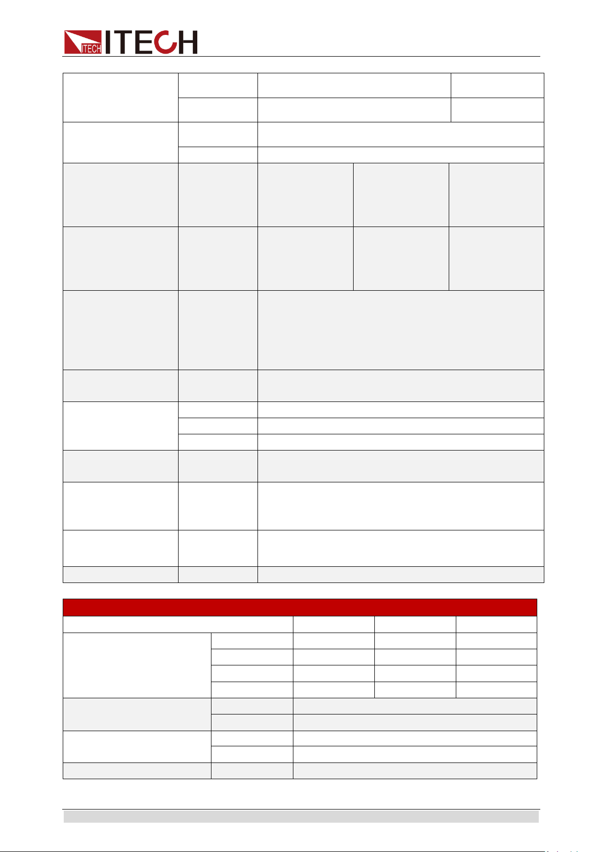
4.1 Major technical parameters
IT6322A
Parameters
CH1
CH2
CH3
Rated values
(0 °C - 40 °C)
Voltage
0~30V
0~30V
0~5V
Voltage limiting
0~31V
0~31V
0~6V
Current
0~3A
0~3A
0~3A
Power
90W
90W
15W
Load regulation
(%of output + offset)
Voltage
≤0.01%+3mV
Current
≤0.1%+3mA
Line regulation
(%of output + offset)
Voltage
≤0.01%+3mV
Current
≤0.1%+3mA
Setup resolution
Voltage
1mV
Current
1mA
Read-back resolution
Voltage
1mV
Current
1mA
Setup accuracy
(Within 12 months)
(25°C ± 5 °C)
(%of output + offset)
Voltage
≤0.03%+10mV
Current
≤0.1%+5mA
Read-back accuracy
(25 °C ± 5 °C)
(%of output + offset)
Voltage
≤0.03%+10mV
Current
≤0.1%+5mA
Ripple and noise
(20Hz-20MHz)
Voltage
(Vp-p)
≤3mVp-p
Voltage (rms)
≤1mVrms
Current
(rms)
≤3mArms
Output Temp. coefficient
(0 °C ~ 40 °C)
(%of output + offset)
Voltage
≤0.03%+10mV
Current
≤0.1%+5mA
Read-back Temp.
coefficient
(%of output + offset)
Voltage
≤0.03%+10mV
Current
≤0.1%+5mA
Parallel setup accuracy
Voltage
≤0.02%+5mV
Current
≤0.1%+20mA
Memory
Save/recall
36 groups
Timer
Function
Output timer
Time set
0.1~99999.9 second
Resolution
0.1 second
Working temperature
0-40°C
Page 39

Technical Specifications
Copyright © Itech Electronic Co., Ltd. 29
Overall Dimension (mm)
W×H×D
255mm×108.7mm×365.3mm
IT6332A
Parameters
CH1
CH2
CH3
Rated values
(0 °C - 40 °C)
Voltage
0-30V
0-30V
0-5V
Voltage
limiting
31V
31V
6V
Current
0-6A
0-6A
0-3A
Power
180W
180W
15W
Load regulation
(%of output +
offset)
Voltage
≤0.01%+3mV
≤0.01%+3mV
≤0.01%+3mV
Current
≤0.01%+3mA
≤0.01%+3mA
≤0.01%+3mA
Line regulation
(%of output +
offset)
Voltage
≤0.01%+3mV
≤0.01%+3mV
≤0.01%+3mV
Current
≤0.01%+3mA
≤0.01%+3mA
≤0.01%+3mA
Setup resolution
Voltage
1mV
1mV
1mV
Current
1mA
1mA
1mA
Read-back
resolution
Voltage
1mV
1mV
1mV
Current
1mA
1mA
1mA
Setup accuracy
(Within 12 months)
(25°C ± 5 °C)
(%of output +
offset)
Voltage
≤0.03%+10mV
≤0.03%+10mV
≤0.03%+10mV
Current
≤0.1%+8mA
≤0.1%+8mA
≤0.1%+5mA
Read-back
accuracy
(25 °C ± 5 °C)
(%of output +
offset)
Voltage
≤0.03%+10mV
≤0.03%+10mV
≤0.03%+10mV
Current
≤0.1%+8mA
≤0.1%+8mA
≤0.1%+5mA
Ripple and noise
(20Hz-20MHz)
Voltage(Vp-p
)
≤4mVp-p
≤4mVp-p
≤3mVp-p
Voltage(rms)
≤1mVrms
≤1mVrms
≤1mVrms
Current (rms)
≤5mArms
≤5mArms
≤4mArms
Output Temp.
coefficient
(0 °C ~ 40 °C)
(%of
output+offset)/
Voltage
≤0.03%+10mV
≤0.03%+10mV
≤0.03%+10mV
Current
≤0.1%+5mA
≤0.1%+5mA
≤0.1%+5mA
Read-back
Temp. coefficient
(0 °C ~ 40 °C)
(%of output+offset)
Voltage
≤0.03%+10mV
Current
≤0.1%+5mA
Series setup
resolution
Voltage
1mV
Current
1mA
Page 40

Technical Specifications
Copyright © Itech Electronic Co., Ltd. 30
Series Read-back
resolution
Voltage
1mV
Current
1mA
Parallel setup
resolution
Voltage
1mV
Current
0 - 9.999A - 1mA
10 - 12A - 10mA
Parallel Read-back
resolution
Voltage
1mV
Current
0 - 9.999A - 1mA
10 - 12A - 10mA
Parallel setup
accuracy
Voltage
≤0.02%+5mV
-
Current
≤0.1%+30mA
-
Voltage waveform
rise time
10%-90% change
time
Typical value
< 100 ms
< 100 ms
< 100 ms
Voltage waveform
fall time
10%-90% change
time
Typical value
< 500 ms
< 500 ms
< 100 ms
Voltage dynamic
response time,
Load change
50%-100%
Restore to 50
mV
< 75 us
Memory
Save/recall
36 groups
Timer
Function
Output timer
Time set
0.1 second-99999.9 second
Resolution
0.1 second
Working
temperature
0-40°C
Dimension (Bare
metal, mounted to
the cabinet)
W×H×D
214.5mm×88.2mm×451.6mm
Dimension
(Overall)
W×H×D
255.3mm×108.7mm×471mm
Weight
15Kg
IT6333A
Parameters
CH1
CH2
CH3
Rated values
(0 °C - 40 °C)
Voltage
0-60V
0-60V
0-5V
Voltage
limiting
61V
61V
6V
Current
0-3A
0-3A
0-3A
Power
180W
180W
15W
Page 41

Technical Specifications
Copyright © Itech Electronic Co., Ltd. 31
Load regulation
(%of output +
offset)
Voltage
≤0.01%+3mV
≤0.01%+3mV
≤0.01%+3mV
Current
≤0.01%+3mA
≤0.01%+3mA
≤0.01%+3mA
Line regulation
(%of output +
offset)
Voltage
≤0.01%+3mV
≤0.01%+3mV
≤0.01%+3mV
Current
≤0.01%+3mA
≤0.01%+3mA
≤0.01%+3mA
Setup resolution
Voltage
1mV
1mV
1mV
Current
1mA
1mA
1mA
Read-back
resolution
Voltage
1mV
1mV
1mV
Current
1mA
1mA
1mA
Setup accuracy
(Within 12 months)
(25°C ± 5 °C)
(%of output +
offset)
Voltage
≤0.03%+10mV
≤0.03%+10mV
≤0.03%+10mV
Current
≤0.1%+5mA
≤0.1%+5mA
≤0.1%+5mA
Read-back
accuracy
(25 °C ± 5 °C)
(%of output +
offset)
Voltage
≤0.03%+10mV
≤0.03%+10mV
≤0.03%+10mV
Current
≤0.1%+5mA
≤0.1%+5mA
≤0.1%+5mA
Ripple and noise
(20Hz-20MHz)
Voltage(Vp-p
)
(10°C - 40°C)
≤4mVp-p
≤4mVp-p
≤3mVp-p
Voltage(Vp-p
)
(0°C - 10°C)
≤4.5mVp-p
≤4.5mVp-p
≤4.5mVp-p
Voltage(rms)
≤1mVrms
≤1mVrms
≤1mVrms
Current (rms)
≤4mArms
≤4mArms
≤4mArms
Output Temp.
coefficient
(0 °C ~ 40 °C)
(%of output+offset)
Voltage
≤0.03%+10mV
≤0.03%+10mV
≤0.03%+10mV
Current
≤0.1%+5mA
≤0.1%+5mA
≤0.1%+5mA
Read-back Temp.
coefficient
(%of output+offset)
Voltage
≤0.03%+10mV
Current
≤0.1%+5mA
Series setup
resolution
Voltage
0-99V --- 1mV
--
100-120V --- 10mV
Current
1mA
--
Series Read-back
resolution
Voltage
0-99V --- 1mV
--
100-120V --- 10mV
Current
1mA
--
Parallel setup
resolution
Voltage
1mV
Current
1mA
Page 42
Technical Specifications
Copyright © Itech Electronic Co., Ltd. 32
Parallel Read-back
resolution
Voltage
1mV
Current
1mA
Parallel setup
accuracy
Voltage
≤0.02%+10mV
Current
≤0.1%+30mA
Voltage waveform
rise time
10%-90% change
time
Typical value
< 100 ms
< 100 ms
< 100 ms
Voltage waveform
fall time
10%-90% change
time
Typical value
< 1.5 s
< 1.5 s
< 100 ms
Voltage dynamic
response time,
Load change
1.5A(0.5 ms)-3A(0.5
ms)
Restore to 75
mV
< 50 us
Memory
Save/recall
36 groups
Timer
Function
Output timer
Time set
0.1 second-99999.9 second
Resolution
0.1 second
Working
temperature
0-40°C
Dimension (Bare
metal, mounted to
the cabinet)
W×H×D
214.5mm×88.2mm×451.6mm
Dimension
(Overall)
W×H×D
255.3mm×108.7mm×471mm
Weight
15Kg
IT6322B
Parameters
CH1
CH2
CH3
Rated values
(0 °C - 40 °C)
Voltage
0~30V
0~30V
0~5V
Voltage limiting
0~31V
0~31V
0~6V
Current
0~3A
0~3A
0~3A
Power
90W
90W
15W
Load regulation
(%of output + offset)
Voltage
≤0.01%+3mV
Current
≤0.1%+3mA
Line regulation
(%of output + offset)
Voltage
≤0.01%+3mV
Current
≤0.1%+3mA
Setup resolution
Voltage
1mV
Page 43

Technical Specifications
Copyright © Itech Electronic Co., Ltd. 33
Current
1mA
Read-back resolution
Voltage
1mV
Current
1mA
Setup accuracy
(Within 12 months)
(25°C ± 5 °C)
(%of output + offset)
Voltage
≤0.03%+10mV
Current
≤0.1%+5mA
Read-back accuracy
(25 °C ± 5 °C)
(%of output + offset)
Voltage
≤0.03%+10mV
Current
≤0.1%+5mA
Ripple and noise
(20Hz-20MHz)
Voltage
(Vp-p)
≤3mVp-p
Voltage (rms)
≤1mVrms
Current
(rms)
≤3mArms
Output Temp. coefficient
(0 °C ~ 40 °C)
(%of output + offset)
Voltage
≤0.03%+10mV
Current
≤0.1%+5mA
Read-back Temp.
coefficient
(%of output + offset)
Voltage
≤0.03%+10mV
Current
≤0.1%+5mA
Parallel setup accuracy
Voltage
≤0.02%+5mV
Current
≤0.1%+20mA
Memory
Save/recall
36 groups
Timer
Function
Output timer
Time set
0.1~99999.9 second
Resolution
0.1 second
Working temperature
0-40°C
Overall Dimension (mm)
W×H×D
255mm×108.7mm×366mm
IT6332B
Parameters
CH1
CH2
CH3
Rated values
(0 °C - 40 °C)
Voltage
0-30V
0-30V
0-5V
Voltage
limiting
31V
31V
6V
Current
0-6A
0-6A
0-3A
Power
180W
180W
15W
Load regulation
(%of output +
offset)
Voltage
≤0.01%+3mV
≤0.01%+3mV
≤0.01%+3mV
Current
≤0.01%+3mA
≤0.01%+3mA
≤0.01%+3mA
Line regulation
(%of output +
offset)
Voltage
≤0.01%+3mV
≤0.01%+3mV
≤0.01%+3mV
Current
≤0.01%+3mA
≤0.01%+3mA
≤0.01%+3mA
Setup resolution
Voltage
1mV
1mV
1mV
Current
1mA
1mA
1mA
Page 44

Technical Specifications
Copyright © Itech Electronic Co., Ltd. 34
Read-back
resolution
Voltage
1mV
1mV
1mV
Current
1mA
1mA
1mA
Setup accuracy
(Within 12 months)
(25°C ± 5 °C)
(%of output +
offset)
Voltage
≤0.03%+10mV
≤0.03%+10mV
≤0.03%+10mV
Current
≤0.1%+8mA
≤0.1%+8mA
≤0.1%+5mA
Read-back
accuracy
(25 °C ± 5 °C)
(%of output +
offset)
Voltage
≤0.03%+10mV
≤0.03%+10mV
≤0.03%+10mV
Current
≤0.1%+8mA
≤0.1%+8mA
≤0.1%+5mA
Ripple and noise
(20Hz-20MHz)
Voltage(Vp-p
)
≤4mVp-p
≤4mVp-p
≤3mVp-p
Voltage(rms)
≤1mVrms
≤1mVrms
≤1mVrms
Current (rms)
≤5mArms
≤5mArms
≤4mArms
Output Temp.
coefficient
(0 °C ~ 40 °C)
(%of
output+offset)/
Voltage
≤0.03%+10mV
≤0.03%+10mV
≤0.03%+10mV
Current
≤0.1%+5mA
≤0.1%+5mA
≤0.1%+5mA
Read-back
Temp. coefficient
(0 °C ~ 40 °C)
(%of output+offset)
Voltage
≤0.03%+10mV
Current
≤0.1%+5mA
Series setup
resolution
Voltage
1mV
Current
1mA
Series Read-back
resolution
Voltage
1mV
Current
1mA
Parallel setup
resolution
Voltage
1mV
Current
0 - 9.999A - 1mA
10 - 12A - 10mA
Parallel Read-back
resolution
Voltage
1mV
Current
0 - 9.999A - 1mA
10 - 12A - 10mA
Parallel setup
accuracy
Voltage
≤0.02%+5mV
-
Current
≤0.1%+30mA
-
Voltage waveform
rise time
10%-90% change
time
Typical value
< 100 ms
< 100 ms
< 100 ms
Page 45

Technical Specifications
Copyright © Itech Electronic Co., Ltd. 35
Voltage waveform
fall time
10%-90% change
time
Typical value
< 500 ms
< 500 ms
< 100 ms
Voltage dynamic
response time,
Load change
50%-100%
Restore to 50
mV
< 75 us
Memory
Save/recall
36 groups
Timer
Function
Output timer
Time set
0.1 second-99999.9 second
Resolution
0.1 second
Working
temperature
0-40°C
Dimension (Bare
metal, mounted to
the cabinet)
W×H×D
214.5mm×88.2mm×451.6mm
Dimension
(Overall)
W×H×D
255.3mm×108.7mm×471mm
Weight
15Kg
IT6333B
Parameters
CH1
CH2
CH3
Rated values
(0 °C - 40 °C)
Voltage
0-60V
0-60V
0-5V
Voltage
limiting
61V
61V
6V
Current
0-3A
0-3A
0-3A
Power
180W
180W
15W
Load regulation
(%of output +
offset)
Voltage
≤0.01%+3mV
≤0.01%+3mV
≤0.01%+3mV
Current
≤0.01%+3mA
≤0.01%+3mA
≤0.01%+3mA
Line regulation
(%of output +
offset)
Voltage
≤0.01%+3mV
≤0.01%+3mV
≤0.01%+3mV
Current
≤0.01%+3mA
≤0.01%+3mA
≤0.01%+3mA
Setup resolution
Voltage
1mV
1mV
1mV
Current
1mA
1mA
1mA
Read-back
resolution
Voltage
1mV
1mV
1mV
Current
1mA
1mA
1mA
Setup accuracy
(Within 12 months)
(25°C ± 5 °C)
(%of output +
offset)
Voltage
≤0.03%+10mV
≤0.03%+10mV
≤0.03%+10mV
Current
≤0.1%+5mA
≤0.1%+5mA
≤0.1%+5mA
Read-back
Voltage
≤0.03%+10mV
≤0.03%+10mV
≤0.03%+10mV
Page 46

Technical Specifications
Copyright © Itech Electronic Co., Ltd. 36
accuracy
(25 °C ± 5 °C)
(%of output +
offset)
Current
≤0.1%+5mA
≤0.1%+5mA
≤0.1%+5mA
Ripple and noise
(20Hz-20MHz)
Voltage(Vp-p
)
(10°C - 40°C)
≤4mVp-p
≤4mVp-p
≤3mVp-p
Voltage(Vp-p
)
(0°C - 10°C)
≤4.5mVp-p
≤4.5mVp-p
≤4.5mVp-p
Voltage(rms)
≤1mVrms
≤1mVrms
≤1mVrms
Current (rms)
≤4mArms
≤4mArms
≤4mArms
Output Temp.
coefficient
(0 °C ~ 40 °C)
(%of output+offset)
Voltage
≤0.03%+10mV
≤0.03%+10mV
≤0.03%+10mV
Current
≤0.1%+5mA
≤0.1%+5mA
≤0.1%+5mA
Read-back Temp.
coefficient
(%of output+offset)
Voltage
≤0.03%+10mV
Current
≤0.1%+5mA
Series setup
resolution
Voltage
0-99V --- 1mV
--
100-120V --- 10mV
Current
1mA
--
Series Read-back
resolution
Voltage
0-99V --- 1mV
--
100-120V --- 10mV
Current
1mA
--
Parallel setup
resolution
Voltage
1mV
Current
1mA
Parallel Read-back
resolution
Voltage
1mV
Current
1mA
Parallel setup
accuracy
Voltage
≤0.02%+10mV
Current
≤0.1%+30mA
Voltage waveform
rise time
10%-90% change
time
Typical value
< 100 ms
< 100 ms
< 100 ms
Voltage waveform
fall time
10%-90% change
time
Typical value
< 1.5 s
< 1.5 s
< 100 ms
Voltage dynamic
response time,
Load change
Restore to 75
mV
< 50 us
Page 47

Technical Specifications
Copyright © Itech Electronic Co., Ltd. 37
1.5A(0.5 ms)-3A(0.5
ms)
Memory
Save/recall
36 groups
Timer
Function
Output timer
Time set
0.1 second-99999.9 second
Resolution
0.1 second
Working
temperature
0-40°C
Dimension (Bare
metal, mounted to
the cabinet)
W×H×D
214.5mm×88.2mm×451.6mm
Dimension
(Overall)
W×H×D
255.3mm×108.7mm×471mm
Weight
15Kg
Parameters
IT6322C
Rated values
(0 °C - 40 °C)
Voltage
0~30V×2,0~5V×1
Current
0~3A×2,0~3A×1
Voltage limiting
0~31V×2,0~6V×1
Load regulation
(%of output + offset)
Voltage
≤0.01%+3mV
Current
≤0.1%+3mA
Line regulation
(%of output + offset)
Voltage
≤0.01%+3mV
Current
≤0.1%+3mA
Setup resolution
Voltage
1mV
Current
1mA
Read-back resolution
Voltage
1mV
Current
1mA
Setup accuracy
(Within 12 months)
(25°C ± 5 °C)
(%of output + offset)
Voltage
≤0.03%+10mV
Current
≤0.1%+5mA
Read-back accuracy
(25 °C ± 5 °C)
(%of output + offset)
Voltage
≤0.03%+10mV
Current
≤0.1%+5mA
Ripple and noise
Voltage
≤1mVrms/3mVp-p
Current
≤3mArms
Output Temp.
coefficient
(0 °C ~ 40 °C)
(%of output+offset)
Voltage
≤0.03%+10mV
Current
≤0.1%+5mA
Read-back Temp.
coefficient
Voltage
≤0.03%+10mV
Current
≤0.1%+5mA
Page 48

Technical Specifications
Copyright © Itech Electronic Co., Ltd. 38
(%of output+offset)
Series setup
resolution
Voltage
1mV
Current
1mA
Series readback
resolution
Voltage
1mV
Current
1mA
Parallel setup
resolution
Voltage
1mV
Current
1mA
Parallel readback
resolution
Voltage
1mV
Current
1mA
Parallel setup
accuracy
Voltage
≤0.02%+5mV
Current
≤0.1%+20mA
Voltage waveform rise
time
10%-90%
≤150ms
Voltage waveform fall
time
90%-10%
CH1/CH2≤2.5s, CH3≤0.2s
Dynamic response
time
Restore to 50mV
50%-100%
Freq=1k
100us (Typical value)
Memory
Save/recall
36 groups
Timer
Time set
0.1~99999.9 second
Resolution
0.1 second
Function
Output timer
IT6332C
Parameters
CH1
CH2
CH3
Rated values
(0 °C - 40 °C)
Voltage
0-30V
0-30V
0-5V
Voltage
limiting
31V
31V
6V
Current
0-6A
0-6A
0-3A
Power
180W
180W
15W
Load regulation
(%of output +
offset)
Voltage
≤0.01%+3mV
≤0.01%+3mV
≤0.01%+3mV
Current
≤0.01%+3mA
≤0.01%+3mA
≤0.01%+3mA
Line regulation
(%of output +
offset)
Voltage
≤0.01%+3mV
≤0.01%+3mV
≤0.01%+3mV
Current
≤0.01%+3mA
≤0.01%+3mA
≤0.01%+3mA
Page 49

Technical Specifications
Copyright © Itech Electronic Co., Ltd. 39
Setup resolution
Voltage
1mV
1mV
1mV
Current
1mA
1mA
1mA
Read-back
resolution
Voltage
1mV
1mV
1mV
Current
1mA
1mA
1mA
Setup accuracy
(Within 12 months)
(25°C ± 5 °C)
(%of output +
offset)
Voltage
≤0.03%+10mV
≤0.03%+10mV
≤0.03%+10mV
Current
≤0.1%+8mA
≤0.1%+8mA
≤0.1%+5mA
Read-back
accuracy
(25 °C ± 5 °C)
(%of output +
offset)
Voltage
≤0.03%+10mV
≤0.03%+10mV
≤0.03%+10mV
Current
≤0.1%+8mA
≤0.1%+8mA
≤0.1%+5mA
Ripple and noise
(20Hz-20MHz)
Voltage(Vp-p)
≤4mVp-p
≤4mVp-p
≤3mVp-p
Voltage(rms)
≤1mVrms
≤1mVrms
≤1mVrms
Current (rms)
≤5mArms
≤5mArms
≤4mArms
Output Temp.
coefficient
(0 °C ~ 40 °C)
(%of
output+offset)/
Voltage
≤0.03%+10mV
≤0.03%+10mV
≤0.03%+10mV
Current
≤0.1%+5mA
≤0.1%+5mA
≤0.1%+5mA
Read-back
Temp. coefficient
(0 °C ~ 40 °C)
(%of output+offset)
Voltage
≤0.03%+10mV
Current
≤0.1%+5mA
Series setup
resolution
Voltage
1mV
Current
1mA
Series Read-back
resolution
Voltage
1mV
Current
1mA
Parallel setup
resolution
Voltage
1mV
Current
0 - 9.999A - 1mA
10 - 12A - 10mA
Parallel Read-back
resolution
Voltage
1mV
Current
0 - 9.999A - 1mA
10 - 12A - 10mA
Parallel setup
accuracy
Voltage
≤0.02%+5mV
-
Current
≤0.1%+30mA
-
Voltage waveform
rise time
10%-90% change
time
Typical value
< 100 ms
< 100 ms
< 100 ms
Page 50

Technical Specifications
Copyright © Itech Electronic Co., Ltd. 40
Voltage waveform
fall time
10%-90% change
time
Typical value
< 500 ms
< 500 ms
< 100 ms
Voltage dynamic
response time,
Load change
50%-100%
Restore to 50
mV
< 75 us
Memory
Save/recall
36 groups
Timer
Function
Output timer
Time set
0.1 second-99999.9 second
Resolution
0.1 second
Working
temperature
0-40℃
Dimension (Bare
metal, mounted to
the cabinet)
W×H×D
214.5mm×88.2mm×451.6mm
Dimension
(Overall)
W×H×D
255.3mm×108.7mm×471mm
Weight
15Kg
IT6333C
Parameters
CH1
CH2
CH3
Rated values
(0 °C - 40 °C)
Voltage
0-60V
0-60V
0-5V
Voltage
limiting
61V
61V
6V
Current
0-3A
0-3A
0-3A
Power
180W
180W
15W
Load regulation
(%of output +
offset)
Voltage
≤0.01%+3mV
≤0.01%+3mV
≤0.01%+3mV
Current
≤0.01%+3mA
≤0.01%+3mA
≤0.01%+3mA
Line regulation
(%of output +
offset)
Voltage
≤0.01%+3mV
≤0.01%+3mV
≤0.01%+3mV
Current
≤0.01%+3mA
≤0.01%+3mA
≤0.01%+3mA
Setup resolution
Voltage
1mV
1mV
1mV
Current
1mA
1mA
1mA
Read-back
resolution
Voltage
1mV
1mV
1mV
Current
1mA
1mA
1mA
Setup accuracy
(Within 12 months)
(25°C ± 5 °C)
(%of output +
offset)
Voltage
≤0.03%+10mV
≤0.03%+10mV
≤0.03%+10mV
Current
≤0.1%+5mA
≤0.1%+5mA
≤0.1%+5mA
Read-back
Voltage
≤0.03%+10mV
≤0.03%+10mV
≤0.03%+10mV
Page 51

Technical Specifications
Copyright © Itech Electronic Co., Ltd. 41
accuracy
(25 °C ± 5 °C)
(%of output +
offset)
Current
≤0.1%+5mA
≤0.1%+5mA
≤0.1%+5mA
Ripple and noise
(20Hz-20MHz)
Voltage(Vp-p)
(10°C - 40°C)
≤4mVp-p
≤4mVp-p
≤3mVp-p
Voltage(Vp-p)
(0°C - 10°C)
≤4.5mVp-p
≤4.5mVp-p
≤4.5mVp-p
Voltage(rms)
≤1mVrms
≤1mVrms
≤1mVrms
Current (rms)
≤4mArms
≤4mArms
≤4mArms
Output Temp.
coefficient
(0 °C ~ 40 °C)
(%of output+offset)
Voltage
≤0.03%+10mV
≤0.03%+10mV
≤0.03%+10mV
Current
≤0.1%+5mA
≤0.1%+5mA
≤0.1%+5mA
Read-back Temp.
coefficient
(%of output+offset)
Voltage
≤0.03%+10mV
Current
≤0.1%+5mA
Series setup
resolution
Voltage
0-99V --- 1mV
--
100-120V --- 10mV
Current
1mA
--
Series Read-back
resolution
Voltage
0-99V --- 1mV
--
100-120V --- 10mV
Current
1mA
--
Parallel setup
resolution
Voltage
1mV
Current
1mA
Parallel Read-back
resolution
Voltage
1mV
Current
1mA
Parallel setup
accuracy
Voltage
≤0.02%+10mV
Current
≤0.1%+30mA
Voltage waveform
rise time
10%-90% change
time
Typical value
< 100 ms
< 100 ms
< 100 ms
Voltage waveform
fall time
10%-90% change
time
Typical value
< 1.5 s
< 1.5 s
< 100 ms
Voltage dynamic
response time,
Load change
50%-100%
Restore to 50
mV
< 50 us
Page 52

Technical Specifications
Copyright © Itech Electronic Co., Ltd. 42
Memory
Save/recall
36 groups
Timer
Function
Output timer
Time set
0.1 second-99999.9 second
Resolution
0.1 second
Working
temperature
0-40℃
Dimension (Bare
metal, mounted to
the cabinet)
W×H×D
214.5mm×88.2mm×451.6mm
Dimension
(Overall)
W×H×D
255.3mm×108.7mm×471mm
Weight
15Kg
*The above specifications may be subject to change without prior notice.
4.2 Supplemental Characteristics
Recommended calibration frequency: once a year
Maximum input power:
Model
IT6322A/IT6322B/IT6322C
IT6332A/IT6332B/IT6332C
IT6333A/IT6333B/IT6333C
Power
750VA
1000VA
1000VA
Cooling style: fans
Page 53

Communication with PC
Copyright © Itech Electronic Co., Ltd. 43
Chapter5 Communication with PC
IT6322B/IT6332B/IT6333B Standard configuration have three communication
interface: RS232, USB and GPIB. IT6322A/IT6332A/IT6333A Standard
configuration have two communication interface: RS232 and USB. The
IT6300C series power supply comes standard with three communication
interfaces: LAN, USB (including TMC and VCP), GPIB. The user can choose
any one to realize the communication with the computer. The following
content can help you understanding how to through the computer control
power supply output.
5.1 RS232 interface
The power rear panel has a DB9 needle mouth. Using both for the COM (DB9)
cable connect computer. Press (Shift) + (Menu), setting menu of
configuration the same as the computer configuration before Activation
connection. RS-232 interface can use all of the SCPI command to
programming.
NOTE
In the procedure, the RS-232 must be set consistently with the front panel Config menu
set. If you want to change, please press (Shift)+ (Menu) and access
to menu to change.
RS-232 data format
RS-232 data is a start bit and a stop bit 10 words. Start bit and the number of
stop bits cannot be edit. However, press (Shift)+ (Menu) and
you can choose the following parity item. Parity options are stored in
nonvolatile memory.
Baud rate
Press (Shift)+ (Menu), under the Config menu, you can select
a baud rate which is stored in nonvolatile memory:
4800/9600/19200/38400/57600/115200
RS-232 connection
RS-232 serial port can connect with controller serial port by using a piece of
RS-232 cable with DB-9 interface (such as PC). The following table shows the
plug of the pin.
If your computer connects with RS-232 interface with DB-25 plug, you need a
cable and an adapter which one aspect of the matter is DB-25 plug the other
end is DB-9 plug.
I-setI-set
I-setI-set
I-setI-set
I-setI-set
Page 54

Communication with PC
Copyright © Itech Electronic Co., Ltd. 44
RS232 Pins of Plug
Base pin
number
Description
1
No conjunction
2
TXD, data transmission
3
RXD, data receiving
4
No conjunction
5
GND, grounding
6
No conjunction
7
CTS, clear to send
8
RTS, request to send
9
No conjunction
RS-232 troubleshooting
If you are having trouble communicating over the RS-232 interface, check the
following:
The computer and the power supply must be configured for the same
baud rate, parity, number of data bits, and flow control options. Note that
the power supply is configured for 1 start bit and 1 stop bit (these values
are fixed).
The correct interface cables or adapters must be used, as described
under RS-232 Connector. Note that even if the cable has the proper
connectors for your system, the internal wiring may be incorrect.
The interface cable must be connected to the correct serial port on your
computer (COM1, COM2, etc.).
Communication settings
Before communication, you should first make the following parameters of
power supply and PC matches.
Baud Rate: 9600 (4800/9600/19200/38400/57600/115200). You can enter the
system menu from the front panel, and then set the baud rate.
Data bits: 8
Stop bit: 1
Parity: (none, even, odd)
EVEN Eight data bits have even check
ODD Eight data bits have odd check
NONE Eight data bits have no check
The machine address: (0 ~ 31, the factory a value of 0)
Start Bit
8 Data Bits
Parity=None
Stop Bit
Page 55

Communication with PC
Copyright © Itech Electronic Co., Ltd. 45
5.2 USB interface
You can connect the power and computer by using a USB cable with an A
type port and a B type port. All the power function can program through the
USB.
Note
For the IT6300C series models, USBTMC and USBVCP options are
supported, and USBVCP is a virtual serial port (fixed to 9600/8/N/1).
Before starting communication with the PC, you need to install VCP
related drivers. Please contact ITECH Technical Support for the driver.
The power supply USB488 interface functions are described as follows:
Interface is 488.2 USB488 interface.
Interface receive the request of REN_CONTROL, GO_TO_LOCAL, and
LOCAL_LOCKOUT.
Interface receive command information about MsgID = TRIGGER
USBTMC and pass on TRIGGER order to function layer.
The power USB488 device function are described as follows:
Equipment can read all the forced SCPI command.
Equipment is SR1 enabled.
Equipment is RL1 enabled.
Equipment is DT1 enabled.
5.3 GPIB interface
First of all, you should make power supply GPIB port connecting to computer
GPIB card through the IEEE488 bus. Make sure the connect is firmly and then
set the address, power supply address range is: 1 to 30.You can Enter the
system menu functions by pressing (Shift)+ (Menu). You can
find GPIB address settings through pressing and Input address, then
press to confirm. GPIB address is stored in nonvolatile line storage.
5.4 LAN interface
The LAN interface is assembled in the rear panel of the IT6300C series power
supply. When connect PC, user can use one crossover cable to connect PC
directly. Another way is using one direct-attached network cable to connected
the router (in this case, the computer is also connected to the router).
Note
When using one crossover cable to connect PC directly, the gateway address
should be consistent with that of the PC, and the IP address should be at the same
network segment with the PC’s IP address.
When the instrument and computer are connected to the router, an independent IP
address must be assigned for the instrument.
I-setI-set
Enter
Page 56

Communication with PC
Copyright © Itech Electronic Co., Ltd. 46
The user can view the related information of LAN interface or configure the
communication parameters in configuration menu (Config).
View LAN Interface Information
The operation steps to view the LAN interface information are as follows.
1. Press [Shift]+[I-set] (Menu) to enter into the menu setting interface.
2. Use left/right key or rotate the knob to select Config > Communication
and press [Enter] to confirm.
3. Use left/right key or rotate the knob to select LAN and press [Enter] to
confirm.
The first displayed menu item Info is to view the LAN interface information.
4. Press [Enter] to confirm.
5. Use the left/right key or rotate the knob to view the LAN interface
information. For details, see the information in the Config menu table of
the User Manual.
6. After the setting is completed, press [Esc] to exit.
Configure LAN Interface Information
The configurable parameters are described as follows.
The instrument address
IP: This value is the Internet Protocol (IP) address of the instrument. An IP
address is required for all IP and TCP/IP communications with the instrument.
An IP Address consists of 4 decimal numbers separated by periods. Each
decimal number ranges from 0 through 255 with no leading zeros (for
example, 169.254.2.20).
IP Mask: This value is used to enable the instrument to determine if a client IP
address is on the same local subnet. The same numbering notation applies as
for the IP Address. When a client IP address is on a different subnet, all
packets must be sent to the Default Gateway.
Gate: This value is the IP Address of the default gateway that allows the
instrument to communicate with systems that are not on the local subnet, as
determined by the subnet mask setting. The same numbering notation applies
as for the IP Address. A value of 0.0.0.0 indicates that no default gateway is
defined.
DNS1: This field enters the primary address of the server. Contact your LAN
administrator for server details. The same numbering notation applies as for
the IP Address. A value of 0.0.0.0 indicates that no default server is defined.
DNS is an internet service that translates domain names into IP addresses. It
is also needed for the instrument to find and display its hostname assigned by
the network. Normally, DHCP discovers the DNS address information; you
only need to change this if DHCP is unused or not functional.
DNS2: This field enters the secondary address of the server. Contact your
LAN administrator for server details. The same numbering notation applies as
for the IP Address. A value of 0.0.0.0 indicates that no default server is
defined.
Socket Port: This value indicates the port number corresponding to the
Page 57

Communication with PC
Copyright © Itech Electronic Co., Ltd. 47
Raw-socket service.
LAN Server
The configurable services include: mDNS, Ping, Telnet, Web, VXI and Raw
Socket.
The operation steps to configure are as follows.
This configures the instrument address (IP Mode).
1. Press [Shift]+[I-set] (Menu) to enter into the menu setting interface.
2. Use left/right key or rotate the knob to select Config >
Communication and press [Enter] to confirm.
3. Use left/right key or rotate the knob to select LAN and press [Enter]
to confirm.
4. Use left/right key or rotate the knob to select Config and press [Enter]
to confirm.
The first displayed menu item IP Mode is to configure the instrument
address.
5. Press [Enter] to confirm.
–
Auto: automatically configure the addressing of the instrument;
–
Manual: manually configure the addressing of the instrument.
6. After the setting is completed, press [Esc] to exit.
7. Restart the instrument and the modified configuration item will take
effect.
This selects the LAN services to enable or disable (Server Config).
1. Press [Shift]+[I-set] (Menu) to enter into the menu setting interface.
2. Use left/right key or rotate the knob to select Config >
Communication and press [Enter] to confirm.
3. Use left/right key or rotate the knob to select LAN and press [Enter]
to confirm.
4. Use left/right key or rotate the knob to select Config and press [Enter]
to confirm.
5. Use left/right key or rotate the knob to select Server Config and
press [Enter] to confirm.
6. Use left/right key or rotate the knob to select the desired service and
press [Enter] to confirm.
7. Rotate the knob to adjust the value and press [Enter] to confirm.
–
On: indicates enable the service
–
Off: indicates disable the service
8. After the setting is completed, press [Esc] to exit.
9. Restart the instrument and the modified configuration item will take
effect.
Reset the LAN to the Default Settings
The operation steps to reset the LAN to the default settings are as follows.
1. Press [Shift]+[I-set] (Menu) to enter into the menu setting interface.
2. Use left/right key or rotate the knob to select Config > Communication
and press [Enter] to confirm.
3. Use left/right key or rotate the knob to select LAN and press [Enter] to
Page 58

Communication with PC
Copyright © Itech Electronic Co., Ltd. 48
confirm.
4. Use left/right key or rotate the knob to select Restore and press [Enter] to
confirm.
–
NO: indicates refuse to reset the LAN to the default settings.
–
YES: indicates reset the LAN to the default settings.
5. After the setting is completed, press [Esc] to exit.
6. Restart the instrument and the modified configuration item will take effect.
Page 59

Appendix
Copyright © Itech Electronic Co., Ltd. 49
Appendix
Specifications of Red and Black Test Lines
ITECH provides you with optional red and black test lines, which individual
sales and you can select for test. For specifications of ITECH test lines and
maximum current values, refer to the table below.
Model
Specification
Cross section
Length
IT-E301/10A
10A
-
1m
IT-E301/30A
30A
6mm2
1.2m
IT-E301/30A
30A
6mm2
2m
IT-E301/60A
60A
20mm2
1.5m
IT-E301/120A
120A
50mm2
2m
IT-E301/240A
240A
70mm2
1m
IT-E301/240A
240A
70mm2
2m
IT-E301/360A
360A
95mm2
2m
For maximum current of AWG copper wire, refer to table blow.
AWG
10
12
14
16
18
20
22
24
26
28
The
Maximum
current
value(A)
40
25
20
13
10 7 5
3.5
2.5
1.7
Note: AWG (American Wire Gage), it means X wire (marked on the wire).
The table above lists current capacity of single wire at working
temperature of 30°C. For reference only.
Page 60

Contact Us
Thanks for purchasing ITECH products. In case of any doubts, please contact us as
follows:
1. Refer to accompanying data disk and relevant manual.
2. Visit ITECH website:www.itechate.com
3. Select the most convenient contact method, for further information.
 Loading...