

Page 1

1
USER’S GUIDE
High Resolution and High Speed
Programmable Power Supply
Models IT6163S/IT6164S/IT6165S
© Copyright 2005 All Rights Reserved
Ver1.1 /July, 2005/ IT6100-527
Page 2

2
About your safe ty ..................................................................................................................................................... 3
General inform ation ......................................................................................................................................... 3
Protection from electric shock ........................................................................................................................ 3
Definition of user s ............................................................................................................................................ 3
Certification and Warranty ...................................................................................................................................... 4
Certification ....................................................................................................................................................... 4
Warranty ............................................................................................................................................................ 4
Limitation of Warranty ............................................................................................................................. 4
Introduction ................................................................................................................................................................ 4
Chapter1 Quick Reference ..................................................................................................................................... 5
1.1 The Front Panel ......................................................................................................................................... 5
1.2 The Rear Panel .......................................................................................................................................... 5
1.3 Preliminary Checkout ................................................................................................................................ 6
1. Check the list of s upplied items......................................................................................................... 6
2. Connect the power cord and turn on the power supply ................................................................ 6
3. Checkout Procedure ........................................................................................................................... 6
1.4 Output Checkout ........................................................................................................................................ 7
1.5 If the power Supply Does Not Turn On.................................................................................................. 8
Chapter 2 Specifications ......................................................................................................................................... 8
2.1 Specifications ............................................................................................................................................. 8
2.2 Supplemental Characteristics.................................................................................................................. 9
Chapter 3 Front-panel Operation .......................................................................................................................... 9
3.1Keyboard Dispos al ................................................................................................................................... 10
Multip le Key Instruction ......................................................................................................................... 10
Function Key Instruction ....................................................................................................................... 10
3.2 Front-panel Operation Overv iew........................................................................................................... 11
3.3 Setting Voltage ......................................................................................................................................... 11
3.4 Setting Current ......................................................................................................................................... 11
3.5 Saving and Recalling Operation ........................................................................................................... 11
3.6 Menu Operation ....................................................................................................................................... 12
3.6.1 Menu Description ......................................................................................................................... 12
3.6.2 Menu Function .............................................................................................................................. 14
3.7 Output Operat ion ..................................................................................................................................... 18
3.8 Remote Sense ......................................................................................................................................... 18
3.9 Milliohm Mete ........................................................................................................................................... 19
3.10 Voltage Meter ......................................................................................................................................... 19
Chapter 4 Remote Operation Mode .................................................................................................................... 20
4.1 Communication cable ............................................................................................................................. 20
IT-E131 RS232 Communication Cable .............................................................................................. 20
IT-E132 USB Communication Cable .................................................................................................. 20
IT-E135 GPIB Communication Cable ................................................................................................. 21
4.2 Communication bet wee n Power Supply and Computer ................................................................... 21
Page 3

3
About your safety
Pease review the following safety precautions before operating our eq uipment.
General informat ion
The following safety precautions should be obs erved before using this pr oduct and any associated
instrumentations. Although some instr uments and accessories would be used with non-hazardous
voltages, there ar e situations where hazardous conditions may be pres ent.
This product is inte nded for use by qualified per sonnel who recognize shock hazards and are familiar
with the safety precautions required to avoid possible injury. Read and follo w a ll installation, oper ation,
and maintenance information carefully befor e using the product. Refer to this manual for complete
product spec ifications.
If the product is used in a manner not specified, the protect ion provided by the product may be
impaired.
Before perform ing any maintenance, disconnect the line cord and all test cables.
Protection from el ectric shock
Operators of this i nstrument must be protected from electric shock at all times. The responsible body
must ensure that operators are prevented access and/or insulated from every connection point. In some
cases, connections must be exposed to potential human contact. Product oper ators in these
circumstances m ust be tr ained to protect themselves from the risk of electric shock. If the circuit is
capable of operating at or above 1000 volts, no conductive part of the circuit may be exposed.
Safety Regulation s
To avo id electric al shock, do not open the cabinet. Refer servicing to qualified personnel only.
To avoid injuries, always disconnect power, discharge circuits, and remove external voltage sources before
touching components.
KEEP AWAY FROM LIVE CIRCUITS.
We cannot accept responsibility for any direct or indirect financial damage or loss of profit that might occur
when usi ng the el e ctr o ni c loa d.
The instrument ch assis a nd cover mu st be connected to a n electrical ground.
Definition of users
Responsible body is the individual or group responsible for the use and maintenance of equipment is
operated within its specifications and operating limits, and for ensuring that operators are adequately
trained.
Operators use the product for its intended function. They must be trained in electrical safety procedures
and proper use of the inst rument. They must be protect ed from electric shock and contact with
hazardous live circuits.
Service is only to be performed by qualified service personnel.
Safety symbols and term s
Connect it to safety earth ground using the wire rec ommended in the user
manual.
The symbol on an instrument indicates that the user should refer to the operating
instructions located in the manual.
High voltage da nger
Page 4

4
Certification and Warranty
Certification
We certify that this product met its published specifications at time of shipment from the factory.
Warranty
This instrument product is warranted against defects in material and workmanship for a period of one
year from date of deliver y. During the warranty period we will, at its option, either repair or replac e
products which prove to be defective. For warranty service, with the excepti on of warranty options, this
product must be returned to a service facility designated by us. Customer shall prepay shipping charges
by (and shall pay all dut y and taxes) for products r eturned to the supplier for warranty service. Except
for products returned to customer from another country, supplier shall pa y for return of products to
customer.
Limitation of Warranty
The foregoing warranty shall not apply to defects resulting from improper or inadequate maintenance by
the Customer, Customer-supplied software or inter facing, unauthorized modification or misuse,
operation outside of the environmental specifications for the product, or improper site preparation and
maintenance.
Introduction
IT6100 Series power supplies are high res olution and high speed pr ogrammable DC power supplies .
This series have very small size of 2U, and they are equipped with 5
me ter. That mea ns you don’t need to invest extra money to purchase digital. This series offer flexible
solution to general laboratory and workshop requirement.
Convenient bench-top features:
• VFD display
• Liner programmabl e power supply with low ripple and noi se
• Very high accuracy and resolution of 0.1mV/0.1mA
• High rise speed ﹤30mS
• Equipped w ith 5
• 4U small si ze can be instal led in standard 19’’ rack or bench top
• Remote cont rol via USB/RS232/GPI B
• Limit vol tage protection
• Over current/temperature protection
• Free software for control and calibration
• Can be used in parallel or series connection
1
digital voltage meter and m Ω meter
2
1
digital voltage meter and m Ω
2
Page 5

5
Chapter1 Quick Reference
1
2
3
4
Ω
1
2
3
4
5
5
1
2
3
4
7
1
2
3
4
5
6
7
5
1.1 The Front Panel
VFD and rotary knob
Power switch ON/OFF
Number Keys
Functio n Keys
Up, down and Enter key
6
Input of V/m
Output terminals
meter
1.2 The Rear Panel
4-Pin Trigger and Remote sensing connectors Power socket
Power switch (110V / 220V)
9-Pin COM port interface connector
4-Pin Trigger and Remote sensing connectors
Cooling window
Page 6

6
1.3 Preliminary Checkout
ERR EEPROM
ERROR CAL
Error Config Data
The following steps help you verify that the power supply ready for use.
1. Check the list of supplied items
Verify that you have received the following it em s with your power supply. If anyt hing is missing, contact
your nearest Sales O ffice.
□ One power cord for your locat ion
□ One user’s manual
□ Calibration Report
□ CD-Rom
□ Communication cable (optional)
2. Connect the power cord and turn on the power supply
W hen you turn on the power supply, the front-panel display will light up briefly whi le t he power supply
performs its power-on self-test. All the VFD annunciators will light up at once. To review the display with
all annunciators, you can check if there is any str oke loss on any annunciator.
3. Checkout Procedure
If the EEPROM was damaged or t he lates t operation data in EEPROM is lost, the VFD will display as
follows:
If the calibration data in EEPROM is lost, the VFD will display as follows:
If the latest state of t he power supply in EEPROM is lost, the VFD will display as follows:
If you press the “shift” button, VFD dis pla ys t he i nf or m at io n of the product t ype, series number v ersion
of software.
Press “Esc” to exit, VFD displays as follows:
The first row is the actual output voltag e value and current value, and the state of power supply; the
second row is voltage value measured by voltage meter, and output voltage value set by power supply.
The first r ow is the actual voltage v alue and current v alue, the state of the power supply. T he second
row is the voltage value tested by voltage meter and the setting voltag e of the power supply.
Sourc: XXV XA Meas: XXV
Ver: 1.50 SN:5975002002
0.000V 0.00000A OFF
0.000V 3.000V
Page 7

7
On/Off
On/Off
Warning: The power supply is shipped from the factor y wit h a power-line cord that has
a plug appro priate for your location. Your pow er supply is equipped with a 3-wire
groundi ng type power cord; the third conductor being the ground. The power supply is
grounded only when the power-line cord is plugged into an appropriate receptacle. Do
not operate your power supply without adequate cabinet ground connection.
1.4 Output Checkout
The following procedures chec k to ensure that the power supply develops its rated outputs and
properly responds to operation from the fr ont panel.
Voltage Output Checkout
The following steps verify basic voltage functions without power supply.
1) Turn on the power supply.
2) Enable the outp uts
Press
3)Set the voltage value
Set some different voltage values, then wait till the Meter mode to check if the VFD displayed
voltage value is t he sam e as the set voltage value, and to check if the VFD displayed current
value is nearly zero.
4) Ensure that the v oltage can be adjusted from zero to the full rated value.
Current Output Checkout
The following steps check basic current func tions with a short across the power supply’s output.
1) Turn on the power supply.
2
)Disable the outout
Press
3) Connect a short across ( +) and (-) output terminals wit h an insulated test lead.
Use a wire size sufficient to handle the maximum current.
4) Enable the output.
5) Adjust the voltage value to 1.0 volt.
Adjust the voltage to 1.0 volt to ensure the power supply is in CC operation mode. The CC
annunciator will t urn on.
6) Adjust the current value.
Set some different voltage values, then wait till the Meter m ode to check if the VFD displayed
current value is t he sam e as the set voltage value, and to check if the VFD displayed voltage
value is nearly zero.
7) Ensure that the cu rrent can be adjusted from zero to the ful l rated value.
8) Turn off the power supply and remove the short wire from the output t erminals.
key to let the ON annunciator and the CV annunciator turn on to light.
key to ensure tha t the output is disabled. The ON annunciator is turned off.
Page 8

8
1.5 If the power Supply Does Not Turn O n
Model
Fuse Descri ption(110VAC)
Fuse Descript ion(220VAC)
IT6163S
IT6164S
IT6165S
parameter
IT6163S
IT6164S
IT6165S
±
Line Regulation
±
voltage
<0.02%+1mV
<0.02%+2mV
<0.02%+1mV
current
<0.01%+1mA
<0.01%+0.5mA
<0.01%+1mA
Setup Resolution
±(%ofoutput+offset)
voltage
1mV
1mV
1mV
current
1mA
0.5mA
1mA
voltage
0.5mV
0.5mV
0.5mV
current
0.5mA
0.1mA
0.5mA
current
≤0.05%+10mA
≤0.05%+5mA
≤0.05%+10mA
current
0.05%+10mA
0.05%+5mV
0.05%+10 mA
Ripple
voltage
≤5mVp-p
≤6mVp-p
≤5mVp-p
current
≤10mArms
≤5mArms
≤10mArms
current
≤0.05%+20mA
≤0.05%+10mA
≤0.05%+20mA
current
≤0.05%+10mA
≤0.05%+5mA
≤0.05%+10mA
Weight (Kg)
45Kg
Use the following steps to help solve problems you might encounter when turning on the i nstrument. If
you need more help, refer to chapter 6 for instructio ns on returning the instrument to the supplier for
service.
1. Verify that there is AC power to the power supply.
First, verif y that the power cord is firmly plugged into the power recept acle on the r ear panel of the
power supply. You should also make sure that the power source you plugged the power supply into is
energized. T hen, verify that the power supply is t urned on.
2. Verify the power-li ne vo ltage setting.
The line voltage is set to the proper value for your country (110VAC or 220VAC) when the power supply
is shipped from the factory. Cha nge the volt age setting if it’s not corr ect.
3. Verify that the correct power-line fuse is installed.
If the fuse was damag ed, pleas e see the table below to replace the fuse for your power supply.
15A 10A
Chapter 2 Specifications
2.1 Specifications
Output Ratings
( 0 °C - 40 °C)
Load Regulation
(%of output+offset)
(%of output+offset)
Readback Resolu tio n
Setup Accuracy
±(%of output+offset)
Readback Accura cy
±(%of output+offset)
(20Hz~20MHz)
Temperature Coefficient
( 0 °C~40 °C)
±(%of output+offset)
Readback Tempe rature
Coefficient
Dimension(mm) 445mmW×180mmH×539mmD
Voltage 0~30V 0~60V 0~40V
current 0~40A 0~20A 0~30A
LVP 0~1200W 0~1200W 0~1200W
voltage <0.05%+25mV <0.05%+15mV <0.05%+20mV
current ≤0.05%+20mA ≤0.05%+10mA ≤0.05%+20mA
voltage ≤0.02%+10mV ≤0.02%+30mV ≤0.02%+10mV
voltage 0.02%+15mV 0.02%+20mV 0.02%+15mV
voltage ≤0.02%+20mV ≤0.02%+30mV ≤0.02%+20mV
voltage 0.02%+20mV 0.02%+30mV 0.02%+20mV
Page 9

9
Ω
2.2 Supplemental Char act er istics
State Storage Memory
Fifteen (50) user-configurable stored stable
Recommended Calibration Interval
Once a year
AC Input Ratings (selectable via switch on the rear pan el)
Option Opt.01: 220VA C ± 10%, 47 to 63 Hz
Option Opt.02: 110 VA C ± 10%, 47 to 63 Hz
Cooling
Fan cooled
Operating Temperature
0 to 40 °C
Storage Temperature
-20 to 70 °C.
Environmental Conditions
Designed for indoor use in an installation cat egory II, pollution degree 2 envir onment. Designed to
operate at maximum relative humidity of 95% and at altitudes of up to 2000 meters.
Chapter 3 Front-panel Operation
So far you h ave lear ned how to install your power supply and do quick start. During the quick star t,
you were briefly introduced to operating from the front panel as you learned how to che ck basic
voltage an d current functions. This chapter describes in detai l the use of the front-panel keys and
shows how they are used to accompl ish power supply operation.
This chapter is divi ded into the following sections:
Front-Panel Operation Overview,
Setting Voltage
Setting C urrent
Storing Operation
Menu Operation
On/Off O peration
Remote Sense Function
m
5
Meter
1
Digital Volt age Meter
2
Page 10

10
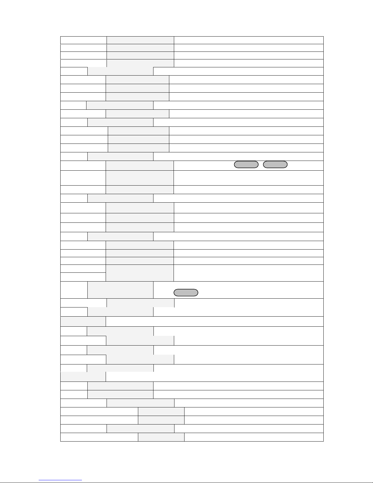
3.1Keyboard Disposal
Ω
Ω
Ω
Set the voltage val ue
Set the current value
Save the cur rently data of the power supply to int ernal regist er
Recall the data from the inter nal register
Set the par ameter of power supply
On/Off
Set the output state of power supply
Shift
Use it with multiple key
Multiple Key Function Key
2211
5544 00
··
88 99
33
66
77
EscEsc
V-set
EnterSave Recall
Shift On/Off
I-set
V-set
I-set
Multiple Key Instruction
V/mΩ: 5
0.1W: The range of m
1
Digital Voltage Meter / mΩ Meter
2
Meter i s 0.1W
1W: The range of m
10W: The range of m
Meter i s 1W
Meter is 10 W
Function Key Instruction
▲:Up key
▼:Down key
Enter: Press it to confirm
Page 11

11
3.2 Front-panel O peration Overview
V-setV-set
Enter
I-setI-set
Enter
Save
Recall
9
0
0
Out on/off
9
The following section describes an overview of the front-panel keys befor e operating your power
supply.
1. The power supply is s hipped from the factory configured in the front-panel operation mode. At
power-on, the power supply is automatically set t o operate in the front-panel operati on mode. When
in this mode, the fr ont panel keys can be used.
2. When the power supply is in remote operation mode, you cannot use the front-panel. A change
between front-panel a nd remote operation modes will not r esult in any change in the output
parameters. Y ou can change the front-panel and rem ote operation modes by computer.
3. The output of the power supply can be enabled or disabled from the front panel by pressing
key. When the output is on, t he ON annunciator will turn on.
4. The VFD display shows t he present operat ing st atus of the power supply wit h annunc iator s. Turn on
the power supply, VFD displays two lines data. The firs t li ne sho ws t he ac tual out put v olta ge value,
current value and the state of the power supply. The second line shows the voltage value tested by
the voltage meter and the outp ut value of the power supply.
3.3 Setting Voltage
The constant voltage range is from 0V to the maximum voltage value of each model. It is ver y easy
for you to set the constant voltag e output. You have 2 solutions t o set the constant voltage value.
Solution1
Step1: Power on the IT6100 series instrum ent
Step2: Press the ▲ and ▼ keys to change the value
Solution2:
Step1: Power on the IT6100 series instrum ent
Step2: Press
Step3: Use the numeric keys to or ▲ and ▼ keys to change the voltage value.
Step4: Press
:
to confirm.
3.4 Setting Curr ent
The c onst ant cur rent outp ut ra nge is from 0A to the maximum current value of eac h type. It is very
easy for you to s et the constant current output.
Step1. Power on the IT6800 series instrum ent
Step2. Press
Step3. Use the numeric keys to or use ▲and ▼keys to change the current value
Step4. Press
key
key to confirm the value
3.5 Saving and Recal ling Operation
You c an use
states in storage register locat ions(1 to 5 0). If the fas t rec all fu nctio n is t urned o n, yo u can re call t he
saved sett ings by pr essing numerical k ey (0~9). You can store the followings: voltage, curr ent, the
maximum output voltag e value, the maximum v oltage value, the constant v oltage value, the constant
current value and the st ep value of voltage.
or
or use the SCPI order *SAV、*RCL to store up to 50 different output
Page 12

12
You can use
Save
Enter
Recall
Enter
MENU
ESC
MENU
Config
Config Init.
Return to t he factory default setup value.
Out Recall
Setting Power-on state of power supply.
On
setup value
off the
supply.
Off<Default>
Disable this funct ion.
PWR-ON Recall
Setting power-on parameter of power supply
On
setup value
off the
Off<Default>
Disable this function.
Key Sound Set
Keypad sound setting.
On<Default>
Enable key sound.
Off
Disable key sound
Knob Lock Set
Setup Rotary knob lock state .
On
Lock Rotary knob.
Off< Default >
Unlock Rotary knob.
Remote Sense
Setup voltage measurement Mode.
On
The power supply will measure voltage from the
remote sense connector.
Off< Default >
fr om the
front panel connector.
ShortCut Recall
Quickly recall t he data stored before
On
Enable this function
Off<Default>
Disable this funct ion
OVP Set
Setting over v oltage protection
On
Enable this function
Off< Default >
Disable this funct ion
Meter Rate Set
Setting the speed of power supply
High
High speed
Low< Default >
Low speed
Baudrate set
Setting baud rate
Baudrate 4800 <
ENTER
and 0~50 numeric key,press
, and store the parameter of IT6100
series into the reg ister.
You c an use
and 0~50 numeric key, press
, and recall the parameter stored before
from the register.
3.6 Menu Operation
3.6.1 Menu Description
Press
complete menu list as following. If press , you could get the selected menu function. Press
back to the previous menu selection page.
to indicate operation mode. View the menu in VFD, and u se ▲ and ▼to scroll through the
W hen us er s t urn o n the power supply; its
will k eep the state of last time as use rs t urned
power
W hen us er s t urn o n the power supply; its
will k eep the state of last time as use rs t urned
power supply.
The power s upply will measur e input value
Page 13
13
Default >
Baudrate 9600
Baudrate 19200
Baudrate 38400
Comm. Parity
Command parity setting.
None< Default >
Even
Odd
Address Set
Setting communication address(range from 0to 254)
Address=**
Port Mode
Select function of port
Trigger< Def >
RI/DIF
DIGITAL I/O
Trig Source
Setting trigger mode
Immediat<Def>
Trigger signals from
Shift
+
Trigger
key
External
Trigger signals from the TRIG connector in the rear
panel.
Bus
Communication command trigger mode.
RI Mode
Control the output mode
Off< Default >
Disable this funct ion
Latching
Live
DFI Source
Discrete Fault Indic ator
Off< Default >
QUES
Question Bit
OPER
Operation Bit
ESB
Event State Bit
RQS
Require Bit
Key Lock Set
Setting keypad password.
Press
Enter
directly to disable the key lock fun ction.
Password=
Exit
System Set
Max Volt. set
Setup the Maximum Voltage.
Max= ﹡﹡﹡﹡
Step Volt Set
Set voltage step
Exit
List Set
Call ListFile
Recall list oper ation file.
Edit ListFile
Edit list operation file.
Continuous
Once
Repeat
Step
Once
Step=﹡﹡﹡﹡
﹡﹡﹡﹡
Page 14
14
Repeat
Save Mode Set
Users can choose 4 ki nds
of memory space to s av e the list
file.
8 X 25 Steps
4 X 50 Steps
2 X 100 Steps
1 X200 Steps
Exit
Out On Timer
time you set.
Timer State
Setting POWER ON timer state
On
When users choose the timer state ON, and then
ON
ON
output will turn off automatically,.
Off< Default >
Timer Set
Setting time of POWER ON timer.
Timer=
S
Exit
Exit
Shift
MENU
ENTER
ENTER
Output t i mer,if yo u s t a rt t hi s funct i on, t he p o w er supply will turnof f a f t er t he
turn on the power supply output, the POWER
TIMER wi ll start working, and when the POWER
TIMER is reach the setup time, the power supply
﹡﹡
3.6.2 Menu Function
Output Recall
This function can help you set the output state when the power supply is powered on. If you select On,
the power supply will keep t he state of last time as it is turned off. If you select Off, t his funct ion is
disabled. Default is On.
Key Sound
This instruction can switch on/off the buzzing sound whe n you press any key, if yo u select On, the
buzzer will sound when any key was pressed. If you select Off, the buzzer will not sound when the keys
were pressed. Default is On.
ShortCut Recall
This function can help you recall the data stored before.
Option:
1) Press
+
2) Press▲、▼to select ShortCut Recall,press
into menu operation, VFD displays Config, press
to confirm.
to confirm.
Page 15

15
3) Press▲、▼to select On 项,press
ENTER
ESC
V-setV-set
I-setI-set
ENTER
Save
ENTER
Shift
MENU
ENTER
ENTER
ENTER
ESC
to confirm.
4) Press
5) Press
two times to esc ape m enu operatio n.
or
, select1to9to set voltage value or current value, press
confirm.
6) Press
press
, VFD displays Store 1 , select1to9to set the register number(range from 0 to 9),
to confirm.
You can recall the data stored before by pressing the regist er num ber.
Overvolt age Prot ection(>OVP Set)
When the output voltage exc eeds t he constant voltage by 5%, or t he connection is unsuccess f ul under
remote sense mode, the power supply will protect itself automatically. The power supply must be
turned on again. When the power is in over voltag e protection, the outp ut is off, and buzzer is mooing.
VFD disp lays as following:
Over Voltage
W hen the power supply with other power supply is in paral lel c onnection, please disable this function.
Setting Communi cation Baud Rate (>BAUDRATE)
This function can help you set communication baud rate. There are 4 kinds of baud rate, 4800HZ,
9600HZ, 19200HZ and 38400HZ. Mak e sure that power’s baud rat e is as the same as your computer
to
before communicatio n. Default baud rate is 4800HZ.
Setting A ddress(>ADDRESS)
This instruction can set the communication address for each power supply. The address range is from 0
to 30. Before the communication, you must make sure that there is same address between the power
supply and the computer. Default address is 0.
Option:
1) Press
+
into menu operation, VFD displays Config, press
confirm.
2) Press▲、▼to select Address Set, press
3) VFD displays Address=**, select0to9and set address, press
4) Press
two times to esc ape m enu operatio n.
to confirm.
to confirm.
Port Mode
The level of the port on the rear panel is TTL, and the port has 3 kinds of function as follows:
TRIGGER: pin1 and pin 2 can be used as the exter nal tr igg er sourc e for power supply, and can control
the list operat ion.
RI/DFI:Inhibit Input can control the output state of power supply, Faul t O utp ut can find fault of power
supply.
DIGITAL I/O:It can read and control output and input state.
to
Page 16

16
Pinmode
Trigger RI/DFI DIG ITAL I/O
1
Trigger in
Inhibit Input
Digital I npu t
2
GND
GND
GND
3
No Use
Fault Out put
Digital Output
4
No Use
GND
GND
Shift
Trigger
Tr i gge r Operation (Shift+Trigger)
The power supply has 3 kinds of trigger mode. You must choose trigger source before trigger operating.
Trigger Key: If this funct ion is enabled, press
operation once.
External trigger signal(TTL): There is a trigger input port on the r ear pane l. When this funct ion is
enabled, pleas e giv e this t rigg er input port a pulse abo ut 5 m S, and the power suppl y will
start trigger operation once.
Bus: W hen this function is enabled, and the power s upply receives or der*TRG or TRIgger, the power
supply will start trigger operation once.
+
, the power supply will start trigger
Remote Inhibit
RI input has 3 modes: LATCHING、L IVE、OFF
LATCHING:When the level of RI port changes from high to low, the output of power supply is off.
LIVE:The output state of power supply changes along with the level of RI port. If the level of RI is high,
the output is on; and the level of RI is low, the output of power supply is off.
OFF: The level state of RI do not affect the output st ate of power supply.
Discrete Fault Indicator
DFI source contains QUES、OPER 、ESB、RQS、OFF.
QUES:The output level of DFI c hang es along with t he s tat e of QUES bit. When QUES bit is 1, DFI
outputs low level. When QUES bit is 0, DFI outputs high level.
OPER:The output level of DFI changes along with the state of OPER bit.
ESB:The output level of DFI changes along with the state of ESB bit.
RQS:The output level of DFI changes along with the state of RQS bit.
OFF:The output level of DFI remains high.
KEY LO CK
This instruction can set a password (1 through 4 digits) to lock the function keys operation. After setting
the password, all the function keys on the front panel will be locked except the OUT on/off key. You
must enter the correct password to unlock them, then you can continue to do the function key operation.
If you don’t want to lock the function keys, please don’t press any number key when you enter the >KEY
LOCK instruction, just press ENTER key to unlock it.
Note: W hen shipped from factory, there is no password and function keys are unlock ed. The start bit of
your desired password shouldn’t be 0.
List Set
Before you edit the list file, please set trigg er source as “immediate” in the menu.
Action:
Page 17

17
1) Press
Shift
Menu
Enter
Enter
Enter
Shift
Menu
Enter
Enter
Enter
Enter
Enter
Enter
Enter
Enter
Enter
Enter
Enter
Enter
Esc
Shift
List
Shift
Trigger
Shift
List
Esc
Shift
List
Shift
Trigger
Shift
List
2) Press up or down key to select “Config”, press
3) Press up or down key to select “Trig Source”, press
4) Press up or down key to select “Immediat”, press
+
into the menu.
to confirm.
to confirm.
to confirm.
You ca n m ak e the output change order by editing every step value of list oper ation. The parameter of
list operation includes the name of list file, output step (no more than 200 steps), step time (the
minimum is 1mS) and every step value. T he list f ile can be stor ed in ROM whose capacity is 4K, and it
can be fast recalled. This stor e area is divided into A, B, C and D four areas. I n area A, there is only 1
group whose capacity is 4Kb. In area B, there are 2 groups and each group’s capacity is 2Kb. In area C,
there 4 groups and each group’s capacity is 1Kb. In area D, there are 8 groups and each group’s
capacity is 512Kb.
If the list operation mode is CONTINUOUS, when you receiving a trigger sig nal, the power supply will
start list operation until the list operat ion is over or a trigger is received again.
Operation
1) Press
2) VFD displays Config,press▼to select List Set,press
:
+
into menu operation.
to confirm.
3) VFD displays Call ListFile,press▼to select Edit ListFile, press
4) VFD displays Continuous,press
5) VFD displays Repeat,press
to confirm.
to confirm,select circle operation.
to confirm.
6) VFD displays List Count= _,press numeric key or move the rotary knob, set circle times( in this
example, count is 2),press
to confirm.
7) VFD displays1th=*.****V, press numeric key or move the rotary knob, set the maximum
voltage, press
to confirm.
8) VFD displays 1th=*.****A, press numeric key or move the rotary knob, set the maximum
current, press
to confirm.
9) VFD displays 1th=*mS, press numeric key or move the rotary knob, set delay time, press
to confirm. The range of delay time is 25mS~6S.
10) VFD displays 2th=*.****V, press numeric key or move the rotary knob, s et the maximum
voltage, press
to confirm.
11) VFD displays 2th=*.****A, press numeric key or move the rotary knob, set the maximum
current, press
to confirm.
12) VFD displays 2th=*mS,press numeric key or move the rotary knob, set delay time, press
to confirm. The range of delay time is 25mS~6S.
13) VFD display Store File_,press numeric key or move the rotary knob, set the register number
(1 to 8), press
14) Press
15) Press
Press
two times to escape menu operation.
+
+
to confirm.
to set the list file, then press
to stop.
+
to run the list file.
If you have edited several list files, you can call the list file that you need by “Call ListFile” function in the
menu. Press
press
two times to exit menu operation. And then press
+
to run the file that you call. press
+
+
to stop running.
to set it,
Page 18

18
TriggerTrigger
Trigger
Trigger
Trigger
Trigger
Trigger
Trigger
Trigger Trigger
On/Off
SENCE
IN
GND
+S
-
S
TR
When the list operation mode is STEP, t he power s upply will com e to next step only after it rec e i v e a
trigger signal.
Digital I/O
When the digital port of the power supply mode is DIGITALI/O and power supply is under remote sense,
you could send SCPI order (DIGital:INPut[:STATe?] and DIGital:OUTPut[:STATe?])to read and set the
state of output and input port.
3.7 Output Operat ion
If you control the power supply by front panel, you can press
power supply is under r emot e sens e , you can s e nd SCPI order (OUT Put ON|OF F) to change the s tate
of output.
and switch the state of output. If
3.8 Remote Sense
The wire connected the power supply and electronic load will produce voltage difference when the
current of the power supply is so big. In order to make the measurement accuracy much accurate, there
are 4 pin trigger and rem ote sensing connect ors on the rear panel and you can use it to m easure the
output voltage of the test ed instrument. You must set remote sense mode bef ore you start remote test
function.
+S,-S:Remote sense port
Page 19

19
IN, GND: t rigger port
+
INPUT -
+
OUTPUT -
5 ½ DVM
100V-MAX
R
Shift
Shift
Shift
+
OUTPUT -
+
INPUT -
5 ½ DVM
100V-MAX
Load
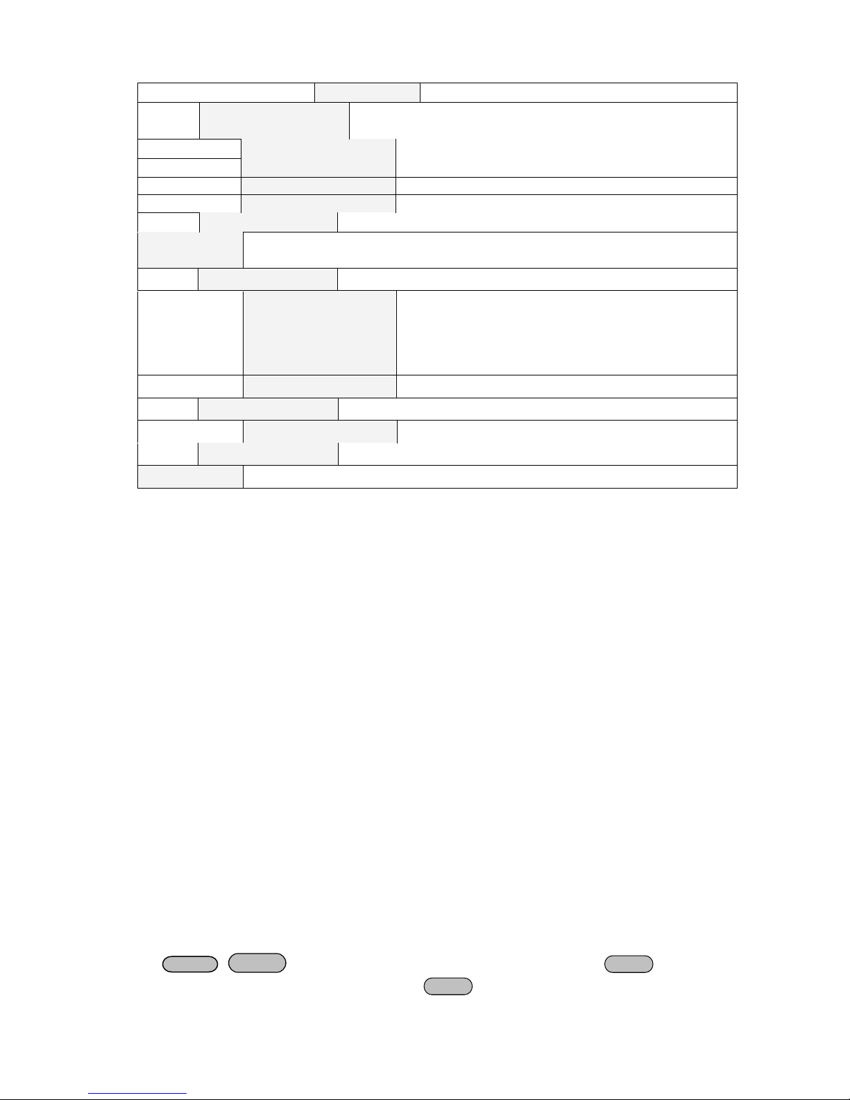
3.9 Milliohm Mete
SOURCE METER can meas ure resistant value accurately and the most resistant value it can measure
is 10Ω. In order to protect the resistant, please select the power range of the resistant before you
me asure it. Wiring dia gram as fo llows:
There are 3 ranges t o be chose: 0.1W、1W、10W.
1) Press
VFD displays Range:
2) Press
+V/mΩ(if VFD displays**.**V, press
**
+0.1W /1W /10W, you can set different range of milliohm meter.
+V/mΩ), set milliohm meter,
3.10 Voltage Meter
Wiring diagram as follows:
Page 20

20
Press
Shift
Shift
PC Load
IT-E131 communication cable
COMPUTER
INSTRUM ENT
RX
TX
IT-E131 ISOLATED
COMMUNICATION CABLE
TTL(5V)RS232 ISOLATION
859666668889942311
IT
COMPUTER
INSTRUM ENT
RX
TX
IT-E131 ISOLATED
COMMUNICATION CABLE
TTL(5V)RS232 ISOLATION
859666668889942311
IT
Power
supply
PC
PC Load
IT-E131 communication cable
COMPUTER
INSTRUM ENT
RX
TX
IT-E131 ISOLATED
COMMUNICATION CABLE
TTL(5V)R S232 ISOLATION
859666668889942311
IT
COMPUTER
INSTRUM ENT
RX
TX
IT-E131 ISOLATED
COMMUNICATION CABLE
TTL(5V)R S232 ISOLATION
859666668889942311
IT
Power
supply
PC
IT-E132 communication cable
meter, VFD displays
+V/mΩ(if VFD displays Range: **,please press
+V/mΩ), set voltage
**.**V, you can begin test the voltage value, the max voltage value is 40V.
Chapter 4 Remote Operation Mode
The DB9 interface connector on the rear panel of the power supply can be transferred to RS-232
interface, the following information will t ell you how to use the computer to control the output of the
power supply.
4.1 Communication cable
IT-E131 RS232 Communication Cable
The DB9 interfac e connector on the rear panel of power supply is TTL voltage level, you can use the
communication cable (IT-E131) to connect the DB9 interface connector of the power supply and the
RS-232 interface connector of computer for the communication.
Computer side TTL→RS232 Cable (IT -E131) PS side
IT-E132 USB Communication Cable
The DB9 interface connector on the rear panel of power supply is TTL v oltage level, you can use
the communication cable (IT-E132) to connect the DB9 interface connector of the power supply
and the USB interface c onnector of computer for the commu nication.
Page 21

21
IT-E135 GPIB Communication Cable
IT-E135 ISOLATED
Serial /IEEE 488 Controller
IT-E135 outer communication adapter
COM interface of
Power supply
GPIB line
The DB9 interface connector on the rear panel of power supply is TTL voltage level, you can use
the GPIB communication cable (IT-E135) to connect the DB9 interface connector of the power
supply, and then connect the G PIB interface of the IT-E135 and computer with GPIB/IEEE 488 line
for the communi cation.
 Loading...