

Page 1

High Resolution and High
Spe e d Pr o gr a m mable Power
Supply
Series IT6100 User’s Manual
Model: IT6121/IT6122/IT6123/IT6151/IT6152/
IT6153/IT6154
Version: V 1.1
Page 2

Notices
© Itech Electronics, Co., Ltd. 2015
No part of this manual may be
reproduced in any form or by any means
(including electronic stor age and
retrieval or translation into a foreig n
language) without prior permission and
written consent from Itech Electronics,
Co., Ltd. as governed by international
copyright laws.
Manual Par t Number
IT6100-402196
Revision
1st Edition: May 26, 2015
Itech Electronics, Co., Ltd.
Trademarks
Pentium is U.S. registered trademarks
of Intel Corporation.
Microsoft, Visual Studio, Windows and
MS Windows are registered trademarks
of Microsoft Corporation in the United
States and/or other countries and
regions.
Warranty
The materials contained in this
document are provided “as is”, and
is subject to change, without prior
notice, in future editions. Further, to
the maximum extent permitted by
applicable laws, ITECH disclaims
all warrants, either express or
implied, with regard to this manual
and any information contained
herein, including but not limited to
the implied warranties of
merchantability and fitness for a
particular purpose. ITECH shall
not be held liable for errors or for
incidental or indirect damages in
connection with the furnishing, use
or application of this document or of
any information contained herein.
Should ITECH and the user enter
into a separate written agreement
with warranty terms covering the
materials in this document that
conflict with these terms, the
warranty terms in the separate
agreement shall prevail.
Techn ology Licenses
The hardware and/or software
described herein are furnished under a
license a nd m a y be use d or cop ie d o nly
in accordance with the terms of such
license.
Restricted Rights Legend
Restricted permissions of the U.S.
government. Permissions for software
and technical data which are authorized
to the U.S. Government only include
those for custom provision to end users
ITECH provides this customary
commercial license in software and
technical data pursuant to FAR 12.211
(Technical Data) and 12.212 (Computer
Software) and, for the Department of
Defense, DFARS 252.227-7015
(Technical Data – Commercial Item s)
and DFARS 227.7202-3 (Rights in
Commercial Computer Software or
Computer Software Documentation).
Safety Notices
A CAUTION sign denotes a
hazard.
It calls attention to an operating
procedure or practice that, if not
correctly performed or adhered
to, could result in damage to the
product or loss of im port ant dat a.
Do not proceed beyond a
CAUTION sign until the
indicated conditions are fully
understood and met.
A WARNING sign denotes a
hazard.
It calls attention to an
operating procedure or practice
that, if not correctly performed
or adhered to, could result in
personal injury or death. Do not
proceed beyond a WARNING
sign until the indicated
conditions are fully understood
and met.
NOTE
A NOTE sign denotes important
hint. It calls attention to tips or
supplementary information that
is essential for users to refer to.
Page 3

IT6100 User’s Manual
Direct current
ON (power on)
Alternating current
OFF (power off)
Both direct and alternating
current
Power-on state
Protective conductor terminal
Power-off state
Caution, risk of elect ric shock
Positive terminal
to this manual for specific
Warning or Caution
information)
Frame or chassis termi nal
-
-
Quality Certification and Assurance
We certify that IT6100 series power supply meets all the published specifications.
Warranty
ITECH warrants that the product will be free from defects in material and
workmanship under normal use for a period of one (1) year from the date of
delivery (except those descri bed in the Limitation of Warranty below).
For warranty service or repair, the product must be returned to a service center
designate d by ITECH.
The product returned to ITECH for warranty servi ce must be shipped
PREPAID. And ITECH will pay for return of the product to customer.
If the product is returned to ITECH for warranty service from over seas, all the
freights, duties and other taxes shall be on the account of customer.
Limitation of Warranty
This Warranty w ill be rendered invalid if the product is:
Damage caused by circuit installed by customer or using customer own
product s or accessor ies;
Modified or repai red by customer without author ization;
Damage caused by circuit installed by customer or not operating our products
under desi gnated environment;
The product m odel or serial number i s modified, deleted, removed or illegible;
Damaged as a result of accidents, including but not limited to lightning,
moistur e, fire, improper use or negl igence.
Safety Symbols
Earth (ground) termi nal
Warning, risk of danger (refer
Reference t erminal
Negati ve terminal
Copyright © ITECH Electronics Co., Ltd. i
Page 4

IT6100 User’s Manual
Environmental Conditions
Requirements
Operating temperature
0°C to 40°C
Operating humidity
20%-80% (non-condensation)
Storage temperature
-20°C to 70 °C
Safety Precautions
The following safety precautions must be observed during all phases of operation
of this instrument. Failure to comply with these precautions or specific warnings
elsewher e in this manual will constitute a default under saf ety standards of design,
manufacture and intended use of the instrument. ITECH assumes no liability for
the custo mer’s f ailure to comply with these precautions.
Do not use the instrument if it is damag ed. Before operation, check the casi ng
to see whether it cracks. Do not operat e the instrument in the presence of
inflammable gasses, vapors or dusts.
The power supply is provided with a three-core power line during delivery and
should be connected to a thr ee-core junction box. Before operat ion, be sure
that the power supply is well grounded. Make sure to use the power cord
supplied by ITECH.
Check all marks on the instrument before connect ing the instrument to pow er
supply.
Use electric wires of appropriat e load. All loading wires should be capable of
bearing maximum short -circuit of electronic load without overheating. If there
are multiple loads, each pair of the load power cord must be carr y out the full
rated short-circuit output current of the power securely.
Ensure the voltage fluctuati on of mains supply is less than 10% of the working
voltage range in order to reduce risks of fire and electric shock.
Do not install alternative parts on the instrument or perform any unauthorized
modification.
Do not use the instrument if the detachable co ver is removed or loosen.
To prevent the possibility of accidental injuries, be sure to use the power
adapter su pplied by the m anufacturer only.
Never use the instrument with a li fe-support syst em or any other equipment
subject to safety requirements.
Failure to use the instrument as directed by the manuf acturer may render its
protecti ve featur e s void.
Always clean the casing with a dry cloth. Do not clean t he internals.
Make sure the vent hole is always unblocked.
Environmental Conditions
The instrum ent is designed for indoor use and an area with low condensation. The
tabl e below shows the general environmental requirements for the instrument. The
speed of fan will change intelligently by the temperature of radiator. When the
temperature is up to 40°C, the fan will be on and adjust intelligently when
temperature ch ang es.
Copyright © ITECH Electronics Co., Ltd. ii
Page 5

IT6100 User’s Manual
Altitude
≤2,000m
Pollution degree
Pollution degree 2
Installation category
The CE mark is a registered
trademark of the European
the product complies with all the
relevant European Legal Direct ives.
The instrument complies with the
WEEE Directive (2002/96/EC)
product label indicates that you must
This symbol indicates the time period
during which no hazardous or toxic
substances are expected to leak or
deteriorate during normal use. The
t can be used
Friendly Use Period (EFUP). Upon
expiration of the EFUP, the product
must be immediately recycled.
(WEEE) Directive
This pr oduct compli es with the WEEE Directive (2002/96/EC)
household waste.
Product Cat egory
To return thi s unw ant ed i nstr u ment , co nt act y our ne ar est I T ECH
office.
Ⅱ
NOTE
To make accurate measurements, allow the instrument to warm up for 30 min before
operation.
Regulatory Markings
Community. This CE mark shows that
marking requirement. This affixed
not discard the electrical/electronic
product in domestic household w aste.
expected service life of the product is
10 years. The produc
safely during the 10-year Environment
Waste Electrical and Electronic Equipment (WEEE)
Directive
2002/96/E C Waste Electrical and Electronic Equipment
marking r equirement. Thi s affix product label indicates that you
must not discard the el ectrical/ electronic product in domestic
With ref erence to the equipment classif ications described in the
Annex I of the WEEE Directive, this instrument is classified as a
Copyright © ITECH Electronics Co., Ltd. iii
“Monitoring and Control Instrument” product.
Page 6

IT6100 User’s Manual
IEC 61326-1:2012/ EN 61326 -1:2013 ¹²³
Reference St andards
CISPR 11:2009+A1:2010/ EN 55011:2009+A1:2010 (Group 1, Class A)
IEC 61000-4-2:2008/ EN 61000-4-2:2009
IEC 61000-4-3:2006+A1:2007+A2:2010/ EN 61000-4-3:2006+A1:2008+A2:2010
IEC 61000-4-4:2004+A1:2010/ EN 61000-4-4:2004+A1:2010
IEC 61000-4-5:2005/ EN 61000-4-5:2006
IEC 61000-4-6:2008/ EN 61000-4-6:2009
IEC 61000-4-11:2004/ EN 61000-4-11:2004
Compliance Information
Complies with the essential requirements of the following applicable European
Directives, and carries the CE marking accordingly:
Electroma gnetic Compatibility (EMC) Directive 2014/30/EU
Low-Voltage Directive (Safety) 2014/35/EU
Conforms with the following product standards:
EMC Standard
1. The product is intended for use in non-residential/non-domestic environments. Use of the
product in residential/domestic environments may cause electromagnetic interference.
2. Connection of the instrument to a test object may produce radiations beyond the specified limit.
3. Use high-performance shielded interface cable to ensure conformity with the EMC standards
listed above.
Safety Standard
IEC 61010-1:2010/ EN 61010-1:2010
Copyright © ITECH Electronics Co., Ltd. iv
Page 7

IT6100 User’s Manual
Copyright © ITECH Electronics Co., Ltd. v
CONTENTS
Quality Certific ation and A ssura nce ................................................................................................................ i
Warranty ........................................................................................................................................................... i
Limitat ion of Warranty ..................................................................................................................................... i
Safety Symbol s ................................................................................................................................................. i
Safety Precautions ........................................................................................................................................... ii
Environmental Conditions .............................................................................................................................. ii
Regulatory Markings ...................................................................................................................................... iii
Waste Electrical and Electronic Equipment (WEEE) Directive .................................................................... iii
Compl i ance Information ................................................................................................................................ iv
Chapter1 Ins talling the Instrume nt .............................................................................................................. 1
1.1 Verify i ng the Shi pment.............................................................................................................................. 1
1.2 Instrument Size Introduction ..................................................................................................................... 1
1.3 Adjusting the Carrying Handle ................................................................................................................. 3
1.4 Ra cking Mo unt the Instrument ................................................................................................................. 3
1.5 Connecting the Power Cord ...................................................................................................................... 3
Chapter2 Quick Start ..................................................................................................................................... 5
2.1 Brief Intr o d uct io n ...................................................................................................................................... 5
2.2 Fro nt Panel Introduction ........................................................................................................................... 5
2.3 Keyboard Introduction .............................................................................................................................. 7
2.4 Re ar Panel Introduction ............................................................................................................................. 8
2.5 Power -on Sel ftest ...................................................................................................................................... 9
2.6 Output Checkout ..................................................................................................................................... 11
Chapter3 Functions a nd Characteristics .................................................................................................. 13
3.1 Front-panel Operation Overview ............................................................................................................ 13
3.2 Setti ng Vol t age ......................................................................................................................................... 13
3.3 Setting Current ........................................................................................................................................ 14
3.4 Saving and Recalling Operation ............................................................................................................. 14
3.5 Menu Operation ....................................................................................................................................... 15
3.6 Over Voltage Protection Function ........................................................................................................... 22
3.6 Out put Operation ..................................................................................................................................... 23
3.7 Remote Sense .......................................................................................................................................... 23
3.8 Mill io hm Met er ....................................................................................................................................... 24
3.9 Voltag e M et er .......................................................................................................................................... 24
Chapter4 Technical Specification .............................................................................................................. 26
4.1 Specifications .......................................................................................................................................... 26
4.2 Supplemental Characteristics .................................................................................................................. 27
Chapter5 Remote Oper ation Mode ........................................................................................................... 29
5.1 Communication Cable ............................................................................................................................. 29
5.2 Communication betwe e n Pow e r Su p pl y and Com pu t er ......................................................................... 30
Appendix ............................................................................................................................................................... 31
Specifi c at io n s of Re d and Bl a ck Test Lines .................................................................................................. 31
Page 8

Installing the Instrument
The IT6100 series include:
IT6151/IT6152/IT6153/IT6154
User may select an appropr iate
Cord for details.
x1
It contains IT6100 power supply
documentations.
Ex-factory Test
Report
It is the test report of the
instrument before delivery.
Model IT6120 Series
Chapter1 Installing the Instrument
1.1 Verifying the Shipment
Unpack the box and check the contents before operating the instrument. If wrong
items have been delivered, if items are missing, or if there is a defect with the
appearance of the items, contact the dealer from which you purchased the
instrume nt immediat ely. The package contents include:
Checklist of Package Contents
Item Qty. Model Remarks
IT6100 power
supply
Power cord
USB cable
CD x1 -
Note
Upon verification of the shipment, keep the package and relevant contents thereof in a safe
place. When returning the instrument for warranty service or repair, the specified packing
requirements shall be met. Refer to IT6100 User’s Manual for detailed requirements on
returns.
x1 IT6100 series
IT-E171/IT-E172
x1
x1 -
/IT-E173/IT-E17
4
- -
IT6121/IT6122/IT6123/
power cord that matc hes the
specifications of power socket
used in the area. See the
Section Connecting the Power
User’s Manual, Programming
Guide and other user
IT6100 series power supply has the following optional accessory:
IT-E151:19 inch rac k m ount
IT-E121:RS232 communication cable
IT-E122:USB communi cation cable
IT-E135:GPIB connector
IT-E123:RS485 communication cable
1.2 Instrument Size Introduction
The instrument should be installed at well-ventilated and rational-sized space.
Please select appropriate space f or inst allation based on t he power supply size.
Copyright © ITECH Electronics Co., Ltd. 1
Page 9

Installing the Instrument
Detailed dimensional drawings
Model IT6150 Series
Detailed dimensional drawings
Overall dimensions
Width: 214.5 mm
Height: 88.2 mm
Depth: 354.6 mm
(Unit: mm)
Overall dimensions
Width: 429 mm
Height: 88.2 mm
Depth: 354.6 mm
Copyright © ITECH Electronics Co., Ltd. 2
Page 10

Installing the Instrument
1.3 Adjusting the Carrying Handle
To adjust the po si tion, grasp the handle by t he si des and pul l outw ar d. Then, r otat e
the handl e to the desired position.
Bench-top viewing positions Carrying position
1.4 Racking Mount the Instrument
You can mount the IT6120 and IT6150 series power supply in a standard 19-inch
rack cabinet. For details, please see the corresponding rack mounting installation
instruction.
1.5 Connecting the Power Cord
Before connecting the power cord, please ensure the power switch of the
instrument is turned OFF. Only use the power cord supplied as a standard
accessory. A summary of connection procedures is given below.
AC power input level
IT6120/IT6150 series power supply working voltage is 110V and 220V. Please pay
Copyright © ITECH Electronics Co., Ltd. 3
Page 11

Installing the Instrument
E
N L
E
L N
E
N L
E
L N
IT-E172
attention to the AC power input level as below.
AC power input level:
Option Opt .01: 220VAC ± 10%, 47 to 63 Hz
Option Opt .02: 110 VAC ± 10%, 47 to 63 Hz
Categories of power cords
IT6100 series power supply provides the standard power cords as bel ow.
Please selec t appropriate power cords appropriate to local voltage based on the
specifications of power cords below. If purchased model fails to meet local voltage
requireme nts, please conta ct distri butor or factor y for change.
China
IT-E171
America,
Canada,Japan
Europe
IT-E173
Britain
IT-E174
Copyright © ITECH Electronics Co., Ltd. 4
Page 12

Quick Start
Model
Voltage
Current
Power
IT6121
20V
5A
100W
IT6122
32V
3A
96W
IT6123
72V
1.2A
86W
IT6151
5.2V
60A
312W
IT6152
20V
27A
540W
IT6153
30V
18A
540W
IT6154
60V
9A
540W
2.1 Brief Introduction
IT6100 Series power supplies are high resolution and high speed programmable
DC power supplies. This series have very small size of 2U, and they are equipped
1
with 5
invest extra money to purchase digital meter. This series offer flexible solution to
general laboratory and workshop requirement.
VFD displ ay
Liner programmable power supply with low ripple and noise
Very high accuracy and resolution of 0.1mV/0.1mA
High rise speed<30mS
Equipped with 5
2
digital voltage meter and mΩ meter. That means you don’t need to
1
2
digital voltage meter and mΩ meter
Chapter2 Quick Start
Small size can be installed in standard 19’’ rack or bench top
Remote contr ol via USB/RS232/GPIB
Limit voltage protection
Over curre nt/temperature protection
Free sof tware for control the machine on computer
2.2 Front Panel Introduction
IT6120 Series’ Front Panel as shown below.
Copyright © ITECH Electronics Co., Ltd. 5
Page 13

Quick Start
1
2
3
4
5
6
7
8
6
7
2
1
534
1
2
3
Fig 1.1 IT6120 series’ front panel
VFD display
Rotary knob
Power switch
Numeric keys and ESC key
Function keys
Up , down key and ENTER key
Output termi nals
IT6150 Series’ Front Panel as shown below.
Fig 1.2 IT6150 series’ front panel
VFD display
Rotary knob
Power switch
Copyright © ITECH Electronics Co., Ltd. 6
Page 14

Quick Start
4
5
6
7
8
keys
Name and functions
Power
Power on the instrument.
0~9
Numeric button
Dot mark.
V-setV-set
Set the voltage val ue
I-setI-set
Set the current value
Save
Save the curr entl y data of the power supply to inter nal register
Recall
Recall the data from the internal register
On/Off
Set the output state of power supply
Shift
Use it with multiple key
Up key. Select menu items or increase output voltage in menu
operation.
Down key. Select menu items or decrease output voltage in
menu operati on.
Enter
Shift
Shift
key to realize menu
n and set the corresponding parameters
of power supply.
Shift
Set LIST operation parameters.
Numeric keys and ESC key
Function keys
Up, down key and ENTER key
Input terminals
Output termi nals
2.3 Keyboard Introduction
Detailed descri ption of keys:
Esc key. Exit under any conditions.
Enter key.
Combination keys. Press
(Shift ) button first and then other keys to achieve all
kinds functions in the following table.
+ ( Menu)
Combine with
operatio
+ ( List)
Copyright © ITECH Electronics Co., Ltd. 7
Page 15
Quick Start
Shift
+ ( Trigger)
Cause an immediate tr igger.
Shift
Shift
+ (0.1W)
Shift
+ (1W)
Shift
+ (10W)
Shift
+ ( Local)
Local key. Remote mode switch to local mode.
+ ( V/mΩ)
Voltmeter/Milliohm meter
Milliohm meter 0.1W range.
Milliohm meter 1W range.
Milliohm meter 10W range.
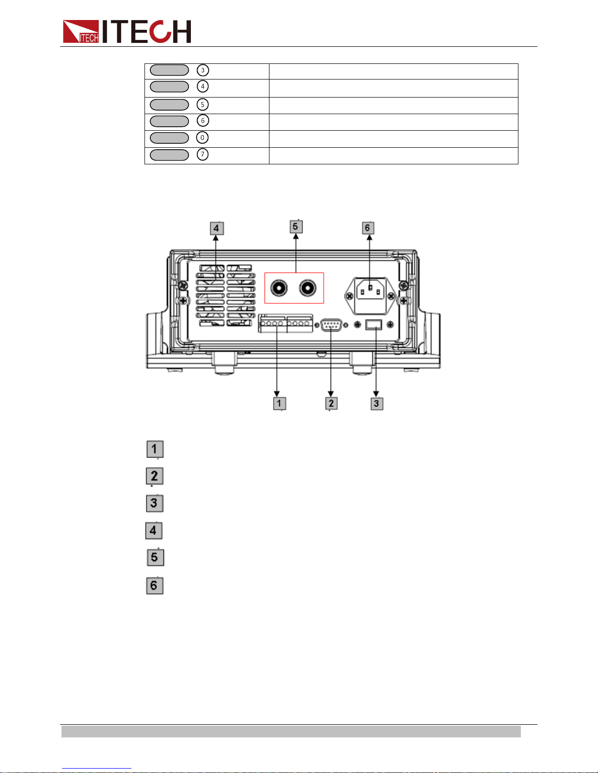
2.4 Rear Panel Introduction
IT6120 Series’ Rear Panel as shown below.
8-Pin Trigger and Remote sensing connector s
9-Pin COM port interface connector
Power switch (110V / 220V)
Cooling window
Voltage measurement terminals
Power socket
IT6150 Series’ Rear Panel as shown below.
Copyright © ITECH Electronics Co., Ltd. 8
Page 16

Quick Start
1
2
3
4
5
0.000V 3.000V
9-Pin COM port interface connector
4-Pin Trigger and Remote sensing connectors
Power socket
Power switch (110V / 220V)
Cooling window
2.5 Power-on Selftest
A successful selftest indicates that the purchased power product meets delivery
standar ds and is avai lable for normal usage.
Before operation, please confirm that you have fully understood the safety
instructions.
To avoid burni ng out, be sure to confirm that power voltage matches with
supply voltage.
Be sure to con nect the main power socket to the power outlet of pr otective
groundi ng. Do not use terminal boar d w ithout protective grounding. Before
operation, be sure that the power supply is well grounded.
To avoid burni ng out, pay at tention to marks of positive and negative polarities
before wiring.
Selftest steps
Normal selftest procedures:
1. Correctly connect the power cor d. Press Power key to start up.
After selftest, VFD display the output voltage and current st atus as below:
2.
0.000V 0.00000A OFF
Copyright © ITECH Electronics Co., Ltd. 9
Page 17

Quick Start
Model
Fuse Sepcification
(110VAC)
Fuse Sepcification
(220VAC)
IT6121
T2.5A 250V
T1.25A 250V
IT6122
T2.5A 250V
T1.25A 250V
IT6123
T2.5A 250V
T1.25A 250V
IT6151
T10A 250V
T5A 250V
IT6152
T10A 250V
T5A 250V
IT6153
T10A 250V
T5A 250V
IT6154
T10A 250V
T5A 250V
Error Information References
The following error information may occur when an error occurs during Power On
self-test:
If the EEPROM was damaged, the V FD will display “EEPROM Error”.
If the last est operation data in EEPROM is lost, then VFD will display “Error
Config Data”.
If the calibration data in EEPROM is lost, then VFD will display “Error
Calibration Data”.
If the fact ory calibration data in EEPROM is lost, and then the VFD will display
“Error Factory Cal.Data”.
Exception handling
If the power supply cannot start normally, please check and take measures by
reference to steps below.
1. Check whether the power cord is correctly connected and confirm whether the
power supply is powered.
Correct wiring of pow er cord => 2
Incorrect wiring of power cord => Re-connect the power cord and check
whether t he excepti on is removed.
2. Check whether the power in On. Power key is under “
” On stat us.
Yes => 3
No => Please check the Power key to start power and check whether the
exception is removed.
3. Check whether the fuse of power supply is bur ned out.
If yes, change fuse. Detailed steps:
1. Use a screwdriver to push and turn the fuse box on the rear panel of the
power supply, refer to the below picture.
Fuse speci fication list
Copyright © ITECH Electronics Co., Ltd. 10
Page 18

Quick Start
On/Off
Out on/off
2. After the fuse box is opened, you can see the fuse in it. Please replace
with a fuse of the same specification..
2.6 Output Checkout
The following procedur es check to ensure that the power supply de velops its rat ed
outputs and properly responds to op eration from the front panel.
2.6.1 Voltage Output Checkout
The following steps verify basic voltage functions without load.
1. Turn on t he power supply.
2. Enable t he outputs
Press key to let the CV announciator turn on to li ght.
3. Set the voltage value
Set some different voltage values, then wait till the Meter mode to check if the
VFD displ ayed voltage value is the s a me as t he set vol t age value, and to check if
the VFD displayed current value is nearly zero.
4. Ensure t hat the voltage can be adjust ed from zero t o the full r ated value.
2.6.2 Current Output Checkout
The following steps check basic current functions with a short across the power
supply ’s output.
1. Turn on t he power supply.
2. Disable the output
Press
3. Connect a short across (+) and (-) output terminals with an insulated test lead.
Use a wire size sufficient to handle the maximum current.
4. Enable t he output
5. Adj ust the vol tage value to 1.0 volt
Adjust the voltage to 1.0 volt to ens ur e t he p ow er supply is in CC operati on mode.
The CC announciator will turn on.
6. Adjust the current value
Set some different voltage values, then wait till the Meter mode to check if the
VFD displ ayed curr ent val ue i s the sa me as t he s et vol t age value, and to c he ck i f
the VFD displayed voltage value is nearly zero
Copyright © ITECH Electronics Co., Ltd. 11
key to ensur e that the output is disabled.
Page 19

Quick Start
7. Ensure t hat the current can be adjusted from zero to the full rated value
8. Turn off the power suppl y and remove the short wire from the output terminals
Copyright © ITECH Electronics Co., Ltd. 12
Page 20

Functions an d Characteristics
On/Off
Chapter3 Functions and Char ac t er istics
This chapter elaborates on the functions and characteristics of IT6100 series
power supply. Contents following sections:
Front-Panel Operation Overview
Setting Voltage
Setting Current
Saving and Recalling Operation
Menu Operation
Output Operation
Remote Sense
Milliohm Meter
Voltage Meter
3.1 Front-panel Operation Overview
The following section describes an overview of the front-panel keys before
operating your power supply.
1. The power supply is shipped from the factory configured in the front-panel
operation mode. At power-on, the power supply is automatically set to operate in
the front-panel operation mode. When in this mode, the front panel keys can be
used.
2. When the power supply is in remote operation mode, you cannot use the
front-panel. A change between front-panel and remote operation modes will not
result in any change in the output parameters. You can change the front-panel and
remote operation modes by computer.
3. The output of the power supply can be enabled or disabled from the front panel
by pressing
4. The VFD display shows the present operating status of the power supply with
announciators. Turn on the power supply, VFD displays two lines data. The first
line show s the act ual out put vol tage value, current value an d t he st at e of t he pow er
supply. The second line shows the voltage value tested by the voltage meter and
the output value of the pow er supply.
key.
3.2 Setting Voltage
The constant voltage range is from 0V to the maximum voltage value of each
model. It is very easy for you to set the constant voltage output. You have 2
solutions to set the constant voltage value.
Solution1:
Step1: Power on the IT6100 series instrument.
Step2: Press the ▲ and ▼ keys to c hange the value.
Solution2:
Step1: Power on the IT6100 series instrument.
Copyright © ITECH Electronics Co., Ltd. 13
Page 21

Functions an d Characteristics
V-setV-set
Enter
V-setV-set
Enter
Save
Recall
Save
Enter
Recall
Enter
9
0
0
I-Set
Enter
9
I-Set
Enter
Step2: Press
.
St ep3: Use the nu meric keys to or ▲ and ▼ keys t o chang e the vol t age
value.
Step4: Press
to confirm.
Solution3:
Step1: Power on the IT6100 ser ies instrument.
Step2: Press
.
Step3: Use rotar y knob to adjust the voltage val ue.
Setp4: Pre ss
to confirm.
3.3 Setting Curr ent
The const ant cur rent o utput r ange is from 0A t o t he m aximum current val ue of ea ch
type. It is very easy for you to set the constant current output.
Solution1:
Step1: Power on the IT6100 series instrument.
Step2: Press key.
Step3: Use the numeric keys to or use ▲and ▼keys to change the
current value.
Step4: Press key to confirm the value.
Solution2:
Step1: Power on the IT6100 series instrument.
Step2: Press key.
Step3: Use rotary knob
to adjust the voltage value.
Step4: Press key to confirm the value.
3.4 Saving and Recal l ing Operation
You can use
50 different output states in storage register locations(1 to 50). If the fast recall
function is turned on, you can recall the saved settings by pressing numerical ke y
(0~9). You can store the followings: the maximum output voltage value, the
voltage setting value, the current setting value and the step value of voltage.
Saving Operation: You can use
and store t he parameter of IT6100 series int o the register.
Recalling Operation: You can use
and recal l the parameter stored before from the register.
or
or use the SCPI order *SAV、*RCL to store up to
and 0~50 numeric key, press
and 0~50 numer i c key, press
,
,
Copyright © ITECH Electronics Co., Ltd. 14
Page 22

Functions an d Characteristics
MENU
ESC
MENU
Config
Config Init.
Return to t he factory default setup value.
Out Recall
Setting Power-on state of power supply.
On
When users turn on the power supply; its setup value will
power
supply.
Off<Default>
Disable this funct ion.
PWR-ON Recall
Setting power-on parameter of power supply
On
When users turn on the power supply; its setup value will
power
supply.
Off<Default>
Disable this funct ion.
Key Sound Set
Keypad sound setting.
On<Default>
Enable key sound.
Off
Disable key sound
Knob Lock Set
Setup Rotary knob lock state .
On
Lock Rotary knob.
Off< Default >
Unlock Rotary knob.
Remote Sense
Setup voltage measurement Mode.
On
The electronic load will measure input voltage fr om t he
remote sense connector.
Off< Default >
The power supply will measure input value from the
front panel connector.
ShortCut Recall
Quickly recall t he data stored before
On
Enable this function
Off<Default>
Disable this funct ion
OVP Set
Setting over voltage protection
On
Enable this function
Off< Default >
Disable this funct ion
Meter Rate Set
Setting the speed of power supply
High
High speed
Low< Default >
Low speed
Baudrate set
Setting baud rate
Baudrate 4800 <
Default >
Baudrate 9600
Baudrate 19200
Baudrate 38400
Comm. Parity
Communication parity bit set.
None< Default >
ENTER
3.5 Menu Operation
Menu Description
Press
to indicate operation mode. View the menu in VFD, and use ▲ and
▼to scroll through the com plete menu list as following. If press , you could
get the selected menu function. Press
back to the previous menu selection
page.
keep the state of last time as use r s t ur ned off the
keep the state of last time as use r s t ur ned off the
Copyright © ITECH Electronics Co., Ltd. 15
Page 23

Functions an d Characteristics
Even
Odd
Address Set
Setting communication address(range from 0to 254)
Address=**
Port Mode
Select function of port
Trigger< Def >
RI/DIF
DIGITAL I/O
Trig Source
Setting trigger mode
Immediat<Def>
Shift
+
Trigger
External
Trigger signals from the TRIG connector in the rear
panel.
Bus
Communication command trigger mode.
RI Mode
Control the output mode
Off< Default >
Disable this funct ion
Latching
Live
DFI Source
Discrete Fault Indic ator
Off< Default >
QUES
Question Bit
OPER
Operation Bit
ESB
Event State Bit
RQS
Require Bit
Key Lock Set
Setting keypad password.
Press
ENTER
directly to disable the key lock function.
Exit
System Set
Max Volt. set
Setup the Maximum Voltage.
Step Volt Set
Set voltage step
Exit
List Set
Call ListFile
Recall list oper ation file.
Edit ListFile
Edit list operation file.
Continuous
Once
Repeat
Step
Once
Repeat
Save Mode Set
Users can choose 4 k inds of memory space to sav e the list
file.
8 X 25 Steps
4 X 50 Steps
2 X 100 Steps
Password= ﹡﹡﹡﹡
Max= ﹡﹡﹡﹡
Trigger signals from
key
Step=﹡﹡﹡﹡
Copyright © ITECH Electronics Co., Ltd. 16
Page 24

Functions an d Characteristics
1 X200 Steps
Exit
Out On
Timer
Output timer,i f you st art thi s func tion, t he pow er sup ply wil l tur n off after the
time you set.
Timer State
Setting POWER ON timer state
On
When users choose the timer state ON, and then tur n
ON TIMER
ON TIMER is
put will
turn off automatically.
Off< Default >
Timer Set
Setting time of POWER ON timer.
Exit
Exit
Shift
Esc
Esc
Shift
MENU
ENTER
ENTER
ENTER
ESC
V-setV-set
I-setI-set
ENTER
Save
0
0
9
9
on the power supply’s outp ut, the POWER
will start working, and when the POWER
reach the setup time, the power supply’s out
Timer= ﹡﹡S
Note:
Press
operations, press
Output Recall
This function can help you set the output state when the power supply is powered
on. If you select On, the power supply will keep the st ate of last time as it is turned
off. If you select Off, this function is disabled. D efault is On.
Key Sound
This inst r ucti on can sw i tch on/ of f the buz z ing so un d w hen y ou pre ss a ny key, if you
select On, the buzzer will sound when any k ey was pressed. If you select Off, the
buzzer wi ll not sound whe n the keys wer e pressed. Default is On.
ShortCut Recall
This f unction can help you recall the data stored before.
Option:
1. Press
2. Press▲ and ▼to select ShortCut Recall, press
press
+1(Menu) to enter menu operation, then press
key to exit the current operation state.
+
into menu operation, VFD displays Config,
to confirm.
to exit. During any function
to confirm.
3. Press▲ and ▼to select On, press
4. Press
5. Press
press
6. Press
Copyright © ITECH Electronics Co., Ltd. 17
two times to escape menu operation.
or
, select to to set volt age value or current value,
to confirm.
, VFD displays Store 1, select to to set the register
to confirm.
Page 25

Functions an d Characteristics
ENTER
Shift
MENU
ENTER
ENTER
ESC
1
Trigger in
Inhibit Input
Digital I npu t
2
GND
GND
GND
3
No Use
Fault Out put
Digital Output
4
No Use
GND
GND
0
9
number(range from 1 to 50), press
to confirm.
7. You can recall the data stored before by pressing the register number.
Setting Communica t ion Baud Rate (>BAUDRATE)
This function can help you set communication baud rate. There are 4 kinds of
baud rate, 4800HZ, 9600HZ, 19200HZ and 38400HZ. Make sure that power ’s
baud rate i s as t he sa me as y our co mput e r bef ore co mm uni cation. Default baud
rate is 4800 HZ.
Setting Commun ication Parity Bit (>Comm.Parity)
This function can set communication parity bit. There are three kinds of
communication parity bit, None, Even and Odd. Make sure that the communi cation
parity bit set to None during remote communication operation. Default
communication parity bit is None.
Setting A ddress (>ADDRESS)
This instruction can set the communication address for each power supply. The
address ran ge i s from 0 to 30. Before t he co mm uni cation, you must make sure that
there is same address between the power supply and the computer. Default
address is 0.
Option:
1. Press
press
2. VFD displays Address= **, select to and set address,
press
3. Press
Setting Port Mode
The level of the port on the rear panel is TTL, and the port has 3 kinds of function
as follows:
TRIGGER: pin1 and pin 2 can be used as the external trigger source for power
supply, and can control the list operation.
RI/DFI: Inhibit Input can control the output state of power supply, Fault Output can
find fault of power supply.
DIG ITAL I/O: It can read and control output and input state.
Pin
+
into menu operation, VFD displays Config,
to confirm.
to confirm.
two times to escape menu operation.
mode
Trigger RI/DFI DIG ITAL I/O
Copyright © ITECH Electronics Co., Ltd. 18
Page 26

Functions an d Characteristics
Shift
Trigger
Shift
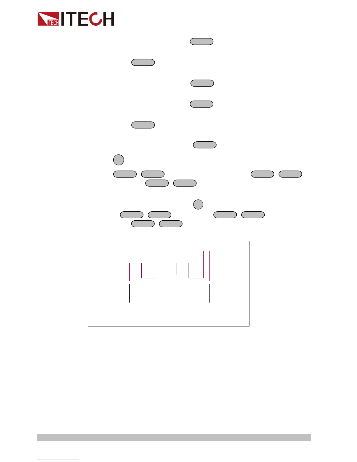
Setting Trigger Operation (Shift+Trigger)
The power supply has 3 kinds of trigger mode. You m ust choose trigger source
before trigger operating.
Trigger Key: If this function is enabled, press
will start trigger operation once.
External trigger signal (TTL): There is a trigger input port on the rear panel.
When this function is enabled, please give this trigger input port a pulse about 5
mS, and the power suppl y will start trigger operation once.
Bus: When this function is enabled, and the power supply receives order*TRG or
TRIgger, t he power supply will st art trigger operation once.
Setting Remote Inhibit
RI input has 3 modes: LATCHING, L IVE, OFF
LATCHING: When the level of RI port changes from high to low, the output of
power supply is off.
LIVE: The output state of power supply changes along with the level of RI p ort. If
the level of RI is high, the output is on; and the level of RI is low, the output of
power supply is off.
OFF: The level state of RI do not affect the output st ate of power supply.
Setting Discrete Fault Indicator
DFI source contains QUES、OPER 、ESB、RQS、OFF.
+
, the power supply
QUES: The output lev el of DFI changes along with the state of QUES bit. When
QUES bit is 1, DFI output s low level. When QUES bit is 0, DFI outputs high level.
OPER: The out put level of DFI changes along with the stat e of OPER bit.
ESB: The output level of DFI changes along with the state of ESB bit.
RQS: The output level of DFI changes along with the state of RQ S bit.
OFF: The output level of DFI remains high.
Setting KEY LOCK
This instruction can set a password (1 through 4 digits) to lock the function keys
operation. After setting the p assw or d, al l the funct i on key s on th e f r ont p anel wil l be
locked except the OUT on/off key. You must enter the correct password to unlock
them, then you can continue to do the function key operation. If you don’t want to
lock the function keys, please don’t press any number key when you enter
the >KEY LOCK instruction, just press ENTER key to unlock it.
Note: When shipped from factory, there is no password and function keys are unlocked. The
start bit of your desired password shouldn’t be 0.
Setting Maximum Output Voltage (>Max Volt. Set)
The range of maximum voltage value is from 0V to full rated output voltage, the
steps ar e as follows:
1. Press
Copyright © ITECH Electronics Co., Ltd. 19
+1(Menu) to enter menu function. VFD displays >Config,
Page 27

Functions an d Characteristics
ENTER
ENTER
0
ENTER
Esc
Shift
Menu
Enter
Enter
Enter
Shift
Menu
Enter
Enter
Enter
Enter
Enter
Enter
Enter
List Set
Press and to select>System Set, then press
2. Press
3. VFD displays Max=73.000V, select
press
4. Press
and to select>Max Volt. Set, then press
-9 to set maximum voltage value,
to confirm.
twice ti me to exit menu oper ation. Default value of M ax Volt. Set is
to confirm.
to confirm.
full rat ed output voltage.
Before you e dit the list file, please set trigger source as “immediate” in the menu.
Action:
1. Press
2. Press up or down key to sel ect “Config”, press
3. Press up or down k ey to select “Trig Source”, press
4. Press up or down key to sel ect “Immediat”, press
+
into the me nu.
to confirm.
to confirm.
to confirm.
You can make the input change order by editing every step value of list operation.
The parameter of list operation includes the name of list file, input step (no more
than 400 step s), step time (the minimum is 1mS) and every step value. The list file
can be stored in ROM whose capacity is 4K, and it can be fast recalled. This store
area is di vi ded i nto A, B, C and D f our ar e as. I n area A, there is onl y 1 gr oup w hose
capacity is 4Kb. In ar ea B, there are 2 groups and each group’ s capacity is 2Kb. In
area C, there 4 groups and each group’s capacity is 1Kb. In area D, there are 8
groups and each group’s capacity is 512b.
If the li st operation mode i s CONTINIOUS, when you receiving a tr igger signal, the
power supply will star t lis t operation until the list operation is over or a trigger is
received a gain.
Operation:
1. Press
2. VFD displays Config, press ▼to select List Set, press
3. VFD displays Call ListFile , press ▼to select Edit ListF ile, press
+
into menu operation.
to confirm.
to
confirm.
4. VFD displays Continuous, press
5. VFD displays Once, press ▼to select Repeat, press
to confirm.
to confirm,
select circle operation.
6. VFD displays Second, press ▼to select MilliSecond, press
to confirm,
select time unit.
7. VFD displays List Count= _, press numeric key or move the rotary knob, set
circle times ( in this example, count is 2),press
to confirm.
8. VFD displays1th=*.****V, press numeric key or move the rotary knob,
set the maximum vol t age, press
to confirm.
9. VFD displays 1th=*.****A, press numeric key or move the rotary knob,
Copyright © ITECH Electronics Co., Ltd. 20
Page 28
Functions and Characteristics
Enter
Enter
Enter
Enter
Enter
Enter
Esc
Shift
List
Shift
Trigger
Shift
List
Esc
Shift
List
Shift
Trigger
Shift
List
Trigger
Trigger
set the maximum current, press
to confirm.
10. VFD displays 1th=*mS, press numeric key or move the rotary knob, set delay
time, press
to confirm.
11. VFD displays 2th=*.****V, press numeric key or move the rotary knob,
set the maximum vol t age, press
to confirm.
12. VFD displays 2th=*.****A, press numeric key or move the rotary knob,
set the maximum current, press
to confirm.
13. VFD displays 2th=*mS, press numeric key or move the rotary knob, set delay
time, press
to confirm.
14. VFD display Store File_, press numeric key or move the rotary knob, set the
register number(1 to 8), pr ess
15. Press
16. Press
two times to escape menu o peration.
+
to set the list file, then press
the list file. Press
+
to stop.
to confirm.
+
to run
If you have edited several list files, you can call the list file that you need by “Call
ListFile” function in the menu. Press
then press
you call. Press
+
to set it, press
+
to stop running.
two times to exit menu operation. And
+
to run the file that
When the list operation mode is STEP, the power supply will go to the next step
when receive a trigger signal.
Copyright © ITECH Electronics Co., Ltd. 21
Page 29

Functions an d Characteristics
Trigger
Trigger
Trigger
Trigger
Trigger
Trigger
Trigger Trigger
Shift
Enter
Enter
Enter
Esc
Shift
Enter
Enter
0
Enter
Esc
Setting Output Timer Function (>Out On Timer)
The loading time of IT6100 power supply can be set. When the timer state is ON,
the power supply output opens and starts with load. When the loading time
reaches the set time, the output will be turned off automatically. W hen the timer
state is OFF, the timer function will be disabled. Default value is OFF.
The detai led operations are as fol lows:
Set timer state:
Digital I/O
1. Press
press
2. Press
and to select>Out On Tim er, then press
and to select>Timer State, then press
3. VFD displays Off<Default> (or On), press
press
4. Press
+1(Menu) to enter menu function, VFD displays>Config,
to confirm.
to confirm.
and to select On or Off, then
to confirm.
twice time to exit the operation.
Set the time of output timer:
1. Press
press
2. Press
and to select>Out On Tim er, then press
and to select>Timer Set, then press
3. VFD displays Timer=20S, press
+1(Menu) to enter menu function, VFD displays>Config,
to confirm.
to confirm.
-9 to set time, then press
to
confirm.
4. Press
twice time to exit the operation.
When the digital port of the power supply mode is DIGITALI/O and power supply is
under remote sense, you could send SCPI order (DIGital:INPut[:STATe?] and
DIGital:OUTPut[:STATe?]) to read and set the state of out put and input port.
3.6 Over Voltage Protection Function
When the output voltage exceeds the constant voltage by 5%, or the connection is
unsuccessful under remote sense mode, the power supply will protect itself
automatically. The power supply must be turned on again. When the power is in
overvoltage protection, the output is off, and buzzer is mooing. VFD displays Over
Voltage.
Copyright © ITECH Electronics Co., Ltd. 22
Page 30

Functions an d Characteristics
On/Off
+S
-
S
+
-
INH GND FLT GND
Over Voltage
When the power supply with other power supply is in paralle l connection, please
disable this functi on.
3.6 Output Operat ion
If you control the power supply by front panel, you can press
the state of output. If power supply is under remote sense, you can send SCPI
order (OUTPut ON|OFF) t o change the state of output.
3.7 Remote Sense
The wire connected the power supply and electronic load will produce voltage
difference when the current of the power supply is so big. In order to make the
measurem ent accuracy mu ch accurate, there are 4 pin trigger and remote s ensing
connectors on the rear panel and you can use it to measure the output voltage of
the tested instrument. You must set remote sense mode before you start remote
test function.
IT6120 8 pin connector in rear panel
+,-: Output port, they are as the same as the output in front panel
+S,-S: Sense port
INH: this port hat multi ple function
and switch
When “Port Mode” in the me nu is set with “Trigger”, INH is trigger por t.
When “Port Mode” in the menu is set with “RI/DIF”, INH can set the output status
on/off. Here INH port has 3 worki ng mo de to choose.
LATCHING: W hen the level of INH port changes from high to low, the output of
power supply is off.
LIVE: The output state of power supply changes along with the level of INH port. If
the level of INH is 1, the output is on; and the level of INH is 0, the output of power
supply is off.
OFF: The level state of INH do not affect the output state of power supply.
When “Port Mode” in the menu is set with “DIGITAL I/O”, INH port becomes the
digital input por t to read input status by communication order.
FLT: This port hat multiple function
When “Port Mode” in the me nu is set with “Trigger”, FLT is an invalid port.
When “Port Mode” in the me nu is set with “RI/DIF”, FLT port can fi nd fault of power
supply.
FLT source contains QUES, OPER, ESB, RQS, OFF.
QUES: The output lev el of FLT changes along with the state of QUES bit. When
Copyright © ITECH Electronics Co., Ltd. 23
Page 31

Functions an d Characteristics
TRIN
-
+
GND
+
-
+
OUTPUT
-
5 ½ DVM
R
+
-
+
OUTPUT
-
5 ½ DVM
R
+
-
+
OUTPUT
-
5 ½ DVM
R
Shift
Shift
Shift
QUES bit is 1, FLT outputs low level. When QUES bit is 0, FLT outputs high level .
OPER: The out put level of FLT changes along with the state of OPER bit.
ESB: The out put level of FLT changes along with the stat e of ESB bit.
RQS: The output level of FLT changes along with the stat e of RQS bit.
OFF: The output level of FLT remains high.
When “Port M ode” i n menu is set with “DIGITAL I/O”, FLT port become s outp ut port
to control the output status by com m unication order.
IT6150 4 pin connector in rear panel
GND, TRIN: Tri gger port
-, +: Remote sense port
3.8 Milliohm Meter
SOURCE METER can measure resistant value accurately and the biggest
resistance it can measure is 1kΩ. In order to protect the resistor, please select the
power range of the resis tor bef ore you measure it. Wiring diagram as follows:
There are 3 r anges to be chosen: 0.1W、1W、10W.
The accuracy of the measurement is <1%, the higher range you select, the more
accurate result you can g et.
Option:
1. Press
m:
**, you can measure resistance value.
2. Press
3.9 Voltage Meter
Copyright © ITECH Electronics Co., Ltd. 24
Wiring diagram as follows:
+V/mΩ(if VFD displays**.**V, press
+0.1W /1W /10W, you can s et different range of milliohm meter.
+V/mΩ), set
Page 32

Functions and Characteristics
+
-
5 ½ DVM
待测物待测物
+
-
5 ½ DVM
待测物
Load
Shift
Ω
Shift
Press
press
voltage val ue.
The accuracy is <0.1%.
+V/m
+V/mΩ), VFD displays**.**V, you can begin to test the
( if VFD displays Range: **,please
Copyright © ITECH Electronics Co., Ltd. 25
Page 33

Technical Specification
Parameter
IT6121
IT6122
IT6123
( 0 °C~40 °C)
Voltage
0 ~20V
0 ~32V
0~72V
Current
0~5A
0~3A
0~1.2A
LVP
0 ~21V
0 ~33V
0 ~73V
±(%of output+offset)
Voltage
Current
≤0.05%+1mA
≤0.05%+0.3mA
±
Voltage
≤0.01%+1mV
≤0.01%+2mV
≤0.05%+0.05m
A
Voltage
0.5mV
2mV
Current
0.1mA
0.02mA
Voltage
0.1mV
0.5mV
Current
0.05mA
0.01mA
0.01mA
Setup
±(%of output+offset)
Readback a ccuracy
±(%of output+offset)
Temperature coefficient,
±(%of output+offset)
Readback temperature,
±(%of output+offset)
Parameter
IT6151
IT6152
IT6153
IT6154
Voltage
<0.05%+20mV<0.05%+15mV
Chapter4 Technical Specification
4.1 Specifications
IT6120 Series DC Power Supply
Output Ratings
Load Regulation
Line Regulation
(%of output+offset)
Setup resolution
Readback resolution
accuracy, 12months,
(25 °C ± 5 °C)
12months,
(25 °C ± 5 °C)
Ripple
(20Hz ~20MHz)
(0 °C~40 °C)
≤0.01%+2mV ≤0.01%+2mV
Current
Voltage
Current
Voltage
Current
Voltage
Current
Voltage
Current
≤0.05%+0.1mA
≤0.03%+3mV ≤0.03%+6mV
≤0.05%+2mA ≤0.05%+1mA
≤0.02%+3mV ≤0.02%+5mV
≤0.05%+2mA ≤0.05%+1mA
≤3mVp-p ≤4mVp-p ≤5mVp-p
≤3mArms ≤3mArms ≤3mArms
≤0.02%+3mV ≤0.02%+5mV
≤0.05%+2mA ≤0.05%+0.5mA
coefficient,
Dimension(mm)
Weight
IT6150 Series High Re solution Power Supply
Output Ratings
( 0 °C~40 °C)
The model of
remote
sense±(%ofoutput
Copyright © ITECH Electronics Co., Ltd. 26
Current
LVP
Voltage
Current
Voltage
Current
0~5.2V 0~20V 0~30V 0~60V
0~60A 0~27A 0~18A 0~9A
0~5.5V 0~21V 0~31V 0~61V
<0.05%+30mV
<0.1%+10mA <0.1%+5mA <0.1%+2mA
≤0.02%+3mV ≤0.02%+5mV
≤0.05%+2mA ≤0.05%+0.5mA
214.5mmW×88.2mmH×354.6mmD
8 kg
<0.05%+10mV
Page 34

Technical Specification
+offset)
Line Regulation
output+offset)
resolution
Voltage
0.1mV
0.5mV
0.5mV
Current
1mA
1mA
1mA
Readback
resolution
Voltage
0.1mV
0.1mV
0.5mV
Current
1mA
0.1mA
0.1mA
Setup
+offset)
Readback
output+offset)
Ripple
(20Hz~20MHz)
Voltage
≤4mVp-p
≤4mVp-p
≤5mVp-p
Current
<15mArms
<5mArms
<3mArms
Temperature
output+offset)
Readback
output+offset)
Dimension(mm)
429mmW×88.2mmH×458.9mmD
IT6120 Series
IT6150 Series
±(%of
Setup
accuracy,12
months±(%of
output
accuracy
±(%of
Coefficient
( 0 °C~40 °C)
±(%of
Voltage
Current
Voltage
Current
Voltage
Current
Voltage
Current
<0.02%+1mV <0.02%+1mV <0.02%+2mV
<0.1%+1mA <0.01%+1mA <0.01%+0.1mA
0.02%+2mV <0.02%+6mV ≤0.02%+12mV
<0.1%+30mA <0.1%+15mA <0.05%+10mA
0.02%+1.5mV 0.02%+3mV 0.02%+6mV
<0.05%+15mA <0.05%+10mA <0.05%+5mA
<0.02%+2mV <0.02%+5mV <0.02%+10mV
<0.1%+30mA <0.1%+15mA <0.05%+5mA
temperature
coefficient±(%of
Weight
Voltage
Current
* The above specifications may be subject to change without prior notice.
<0.02%+2mV <0.02%+5mV <0.02%+10mV
<0.1%+30mA ≤0.05%+10mA ≤0.05%+5mA
29 kg
4.2 Supplemental Char acteristics
State Stor age Memory: Fifty (50) user-configurable stored states
Recomm ended Calibration Interval: Once a year
AC Input Ratings (selectable vi a sw itch on the rear panel):
Option Opt .01: 220VAC ± 10%, 47 to 63 Hz
Option Opt .02: 110 VAC ± 10%, 47 to 63 H
Maximum power:
300VA 1000VA
Cooling: Fan cooled
Operating Tem perat ure: 0 to 40 °C
Storage Temper atur e: -20 to 70 °C
Copyright © ITECH Electronics Co., Ltd. 27
Page 35

Technical Specification
Environmental Conditions
Designed for indoor use in an installation category II, pollution degree 2
environment. Designed to operate at maximum relative humidity of 95% and at
altitudes of up to 2000 meters.
Copyright © ITECH Electronics Co., Ltd. 28
Page 36

Remote Operation Mode
PC Load
IT-E131 communication cable
COMPUTER
INSTRUM ENT
RX
TX
IT-E131 ISOLATED
COMMUNICATION CABLE
TTL(5V)RS232 ISOL ATION
859666668889942311
IT
COMPUTER
INSTRUM ENT
RX
TX
IT-E131 ISOLATED
COMMUNICATION CABLE
TTL(5V)RS232 ISOL ATION
859666668889942311
IT
Power
supply
PC
PC Load
IT-E131 communication cable
COMPUTER
INSTRUM ENT
RX
TX
IT-E131 ISOLATED
COMMUNICATION CABLE
TTL(5V)RS 232 ISOLATION
859666668889942311
IT
COMPUTER
INSTRUM ENT
RX
TX
IT-E131 ISOLATED
COMMUNICATION CABLE
TTL(5V)RS 232 ISOLATION
859666668889942311
IT
Power
supply
PC
IT-E132 communication cable
Chapter5 Remote Operation Mode
The DB9 interface connector on the rear panel of the power supply can be
transferred to RS-232 interface, the following information will tell you how to use
the computer to control the output of t he power supply.
5.1 Communication Cable
IT-E131 RS232 Communicat ion Cable
The DB9 int erf ace connector on the rear p anel of pow er supply is TTL voltage level;
you can use the communication cable (IT-E131) to connect the DB9 interface
connector of the power supply and the RS-232 interface connector of computer for
the communication.
Computer side TTL→RS232 Cable (IT -E131) PS side
IT-E132 USB Communication Cable
The DB9 interface connector on the r ear panel of power suppl y i s TTL volt age l evel;
you can use the communication cable (IT-E132) to connect the DB9 interface
connector of t he p ow er sup pl y and t he US B i nt erf ace co nnect or of c o mput er f or t he
communication.
IT-E135 GPIB Communication Cable
The DB9 int erf ace connector on the rear p anel of pow er supply is TTL voltage level;
you can use t h e GPIB communication cable ( IT-E135) to connect the D B9 interface
Copyright © ITECH Electronics Co., Ltd. 29
Page 37

Remote Operation Mode
IT-E135 ISOLATED
Serial /IEEE 488 Controller
IT-E135 outer communication ad apter
COM interface of
Power supply
GPIB line
connector of the power supply, and then connect the GPIB interface of the IT-E135
and computer with GPIB /IEEE 488 line for the communication.
Copyright © ITECH Electronics Co., Ltd. 30
Page 38

Appendix
Model
Specification
Cross section
Length
IT-E301/10A
10A
-
1m
IT-E301/30A
30A
6mm2
1.2m
IT-E301/30A
30A
6mm2
2m
IT-E301/60A
60A
20mm2
1.5m
IT-E301/120A
120A
50mm2
2m
IT-E301/240A
240A
70mm2
1m
IT-E301/240A
240A
70mm2
2m
IT-E301/360A
360A
95mm2
2m
AWG
10
12
14
16
18
20
22
24
26
28
The
value( A)
40
25
20
13
10 7 5
3.5
2.5
1.7
Appendix
Specifications of Red and Black Test Lines
ITECH provides you with optional red and black test lines, which individual sales
and you can select for test. For specifications of ITECH test lines and maximum
current values, refer to the table below.
For maximum current of AWG copp er wire, refer to table blow.
Maximum
current
Note: AWG ( American Wire Gage), it means X wire ( marked on the wire). The
table above lists current capacity of single wire at working temperature of 30°C.
For reference only.
Copyright © ITECH Electronics Co., Ltd. 31
Page 39

Contact US
Thank you for purchasi ng ITECH products. If you have any doubt about this product, please
contact us as follow.
1. Please refer to the CD-ROM of related user’ s manual in package.
2.
Visit ITECH webs it e www.itechate.com .
3. Select the most convenient contact for further consultation.
 Loading...