

ITech IT6036C-500-180, IT6018C-500-90, IT6006C-500-30, IT6012C-500-60, IT6126C-500-630 User Manual
...Page 1

Bi-directional Programmable
ООО "Техэнком" Контрольно-измерительные приборы и оборудование www.tehencom.com
DC Power Supply
IT6000C Series User Manual
Model: IT6000C Series
Version: V1.0/01,2019
Page 2

Notices
ООО "Техэнком" Контрольно-измерительные приборы и оборудование www.tehencom.com
© Itech Electronic, Co.,
Ltd. 2019
No part of this manual
may be reproduced in any
form or by any means (including electronic storage
and retrieval or translation
into a foreign language)
without prior permission
and written consent from
Itech Electronic, Co., Ltd.
as governed by international copyright laws.
Manual Part Number
Trademarks
Pentium is U.S. registered
trademarks of Intel
Corporation.
Microsoft, Visual Studio,
Windows and MS Windows are registered
trademarks of Microsoft
Corporation in the United
States and/or other countries and regions.
Warranty
The materials contained in this document are provided “as is”, and is subject to change, without prior notice, in
future editions. Further, to the maximum extent permitted by applicable
laws, ITECH disclaims all warrants, either express or implied, with regard to
this manual and any information contained herein, including but not limited
to the implied warranties of merchantability and fitness for a particular purpose. ITECH shall not be held liable
for errors or for incidental or indirect
damages in connection with the furnishing, use or application of this
document or of any information contained herein. Should ITECH and the
user enter into a separate written
agreement with warranty terms covering the materials in this document that
conflict with these terms, the warranty
terms in the separate agreement shall
prevail.
Technology Licenses
The hardware and/or software described herein are furnished under a license and may be used or copied only
in accordance with the terms of such
license.
Restricted Rights Legend
Restricted permissions of the U.S.
government. Permissions for software
and technical data which are authorized to the U.S. Government only include those for custom provision to
end users. ITECH follows FAR 12.211
(technical data), 12.212 (computer
software). DFARS 252.227-7015
(technical data–commercial products)
for national defense and DFARS
227.7202-3 (permissions for commercial computer software or computer
software documents) while providing
the customized business licenses of
software and technical data.
Safety Notices
A CAUTION sign denotes
a hazard. It calls attention
to an operating procedure
or practice that, if not correctly performed or adhered to, could result in
damage to the product or
loss of important data. Do
not proceed beyond a
CAUTION sign until the indicated conditions are
fully understood and met.
A WARNING sign denotes
a hazard. It calls attention
to an operating procedure
or practice that, if not correctly performed or adhered to, could result in
personal injury or death.
Do not proceed beyond a
WARNING sign until the
indicated conditions are
fully understood and met.
A NOTE sign denotes important hint. It calls attention to tips or
supplementary information that is essential for
users to refer to.
Page 3

IT6000C Series User Manual
ООО "Техэнком" Контрольно-измерительные приборы и оборудование www.tehencom.com
Quality Certification and Assurance
We certify that series instrument meets all the published specifications at time
of shipment from the factory.
Warranty
ITECH warrants that the product will be free from defects in material and workmanship under normal use for a period of one (1) year from the date of delivery
(except those described in the Limitation of Warranty below).
For warranty service or repair, the product must be returned to a service center
designated by ITECH.
• The product returned to ITECH for warranty service must be shipped PRE-
PAID. And ITECH will pay for return of the product to customer.
• If the product is returned to ITECH for warranty service from overseas, all
the freights, duties and other taxes shall be on the account of customer.
Limitation of Warranty
This Warranty will be rendered invalid in case of the following:
• Damage caused by circuit installed by customer or using customer own
products or accessories;
• Modified or repaired by customer without authorization;
• Damage caused by circuit installed by customer or not operating our prod-
ucts under designated environment;
• The product model or serial number is altered, deleted, removed or made il-
legible by customer;
• Damaged as a result of accidents, including but not limited to lightning, mois-
ture, fire, improper use or negligence.
Copyright © Itech Electronic Co., Ltd.
I
Page 4

Safety Symbols
ООО "Техэнком" Контрольно-измерительные приборы и оборудование www.tehencom.com
IT6000C Series User Manual
Direct current ON ( power)
Alternating
current
Both direct and
alternating
current
Chassis (earth
ground) symbol.
Earth ( ground)
terminal
Caution Positive terminal
Warning ( refer to
this manual for
specific Warning
or Caution
information)
OFF ( power)
Power-on state
Power-off state
Reference
terminal
Negative terminal
Safety Precautions
The following safety precautions must be observed during all phases of operation of this instrument. Failure to comply with these precautions or specific warn-
ings elsewhere in this manual will constitute a default under safety standards of
design, manufacture and intended use of the instrument. ITECH assumes no liability for the customer’s failure to comply with these precautions.
Copyright © Itech Electronic Co., Ltd.
A chassis
terminal
- -
II
Page 5

IT6000C Series User Manual
ООО "Техэнком" Контрольно-измерительные приборы и оборудование www.tehencom.com
• Do not use the instrument if it is damaged. Before operation, check the
casing to see whether it cracks. Do not operate the instrument in the
presence of inflammable gasses, vapors or dusts.
• The instrument is provided with a power cord during delivery and should
be connected to a socket with a protective earth terminal, a junction box
or a three-phase distribution box. Before operation, be sure that the instrument is well grounded.
• Please always use the provided cable to connect the instrument.
• Check all marks on the instrument before connecting the instrument to
power supply.
• Ensure the voltage fluctuation of mains supply is less than 10% of the
working voltage range in order to reduce risks of fire and electric shock.
• Do not install alternative parts on the instrument or perform any unau-
thorized modification.
• Do not use the instrument if the detachable cover is removed or loosen.
• To prevent the possibility of accidental injuries, be sure to use the power
adapter supplied by the manufacturer only.
• We do not accept responsibility for any direct or indirect financial dam-
age or loss of profit that might occur when using the instrument.
• This instrument is used for industrial purposes, do not apply this product
to IT power supply system.
• Never use the instrument with a life-support system or any other equip-
ment subject to safety requirements.
Copyright © Itech Electronic Co., Ltd.
III
Page 6

IT6000C Series User Manual
ООО "Техэнком" Контрольно-измерительные приборы и оборудование www.tehencom.com
• SHOCK HAZARD Ground the Instrument. This product is provided with
a protective earth terminal. To minimize shock hazard, the instrument
must be connected to the AC mains through a grounded power cable,
with the ground wire firmly connected to an electrical ground (safety
ground) at the power outlet or distribution box. Any interruption of the
protective (grounding) conductor or disconnection of the protective earth
terminal will cause a potential shock hazard that could result in injury or
death.
• Before applying power, verify that all safety precautions are taken. All
connections must be made with the instrument turned off, and must be
performed by qualified personnel who are aware of the hazards involved.
Improper actions can cause fatal injury as well as equipment damage.
• SHOCK HAZARD, LETHAL VOLTAGES This product can output the
dangerous voltage that can cause personal injury, and the operator must
always be protected from electric shock. Ensure that the output electrodes are either insulated or covered using the safety covers provided, so
that no accidental contact with lethal voltages can occur.
• Never touch cables or connections immediately after turning off the in-
strument. Verify that there is no dangerous voltage on the electrodes or
sense terminals before touching them.
• Failure to use the instrument as directed by the manufacturer may ren-
der its protective features void.
• Always clean the casing with a dry cloth. Do not clean the internals.
• Make sure the vent hole is always unblocked.
Environmental Conditions
The instrument is designed for indoor use and an area with low condensation.
The table below shows the general environmental requirements for the
instrument.
Environmental Conditions Requirements
Operating temperature 0°C~40°C
Operating humidity 20%~80%( non-condensation)
Storage temperature -10°C~70 °C
Copyright © Itech Electronic Co., Ltd.
IV
Page 7

Environmental Conditions Requirements
ООО "Техэнком" Контрольно-измерительные приборы и оборудование www.tehencom.com
Altitude Operating up to 2,000 meters
Installation category II
Pollution degree Pollution degree 2
In order to ensure the accuracy of measurement, it is recommended to operate the instrument half an hour after start-up.
Regulation Tag
IT6000C Series User Manual
The CE tag shows that the product
complies with the provisions of all relevant European laws (if the year is
shown, it indicates that the year when
the design is approved).
This instrument complies with the
WEEE directive (2002/96/EC) tag requirements. This attached product
tag shows that the electrical/electronic product cannot be discarded in
household waste.
This symbol indicates that no danger
will happen or toxic substances will
not leak or cause damage in normal
use within the specified period. The
service life of the product is 10 years.
The product can be used safely within
the environmental protection period;
otherwise, the product should be put
into the recycling system.
Copyright © Itech Electronic Co., Ltd.
V
Page 8

IT6000C Series User Manual
ООО "Техэнком" Контрольно-измерительные приборы и оборудование www.tehencom.com
Waste Electrical and Electronic Equipment (WEEE) Directive
Waste electrical and electronic equipment (WEEE) directive, 2002/96/EC
The product complies with tag requirements of the WEEE directive
(2002/96/EC). This tag indicates that
the electronic equipment cannot be
disposed of as ordinary household
waste. Product Category
According to the equipment classification in Annex I of the WEEE directive, this instrument belongs to the
“Monitoring” product.
If you want to return the unnecessary
instrument, please contact the nearest sales office of ITECH.
Copyright © Itech Electronic Co., Ltd.
VI
Page 9

Compliance Information
ООО "Техэнком" Контрольно-измерительные приборы и оборудование www.tehencom.com
Complies with the essential requirements of the following applicable European
Directives, and carries the CE marking accordingly:
• Electromagnetic Compatibility (EMC) Directive 2014/30/EU
• Low-Voltage Directive (Safety) 2014/35/EU
Conforms with the following product standards:
EMC Standard
IEC 61326-1:2012/ EN 61326-1:2013 ¹²³
Reference Standards
CISPR 11:2009+A1:2010/ EN 55011:2009+A1:2010 (Group 1, Class A)
IEC 61000-4-2:2008/ EN 61000-4-2:2009
IT6000C Series User Manual
Safety Standard
IEC 61000-4-3:2006+A1:2007+A2:2010/ EN 61000-4-3:2006+A1:2008+A2:2010
IEC 61000-4-4:2004+A1:2010/ EN 61000-4-4:2004+A1:2010
IEC 61000-4-5:2005/ EN 61000-4-5:2006
IEC 61000-4-6:2008/ EN 61000-4-6:2009
IEC 61000-4-11:2004/ EN 61000-4-11:2004
1. The product is intended for use in non-residential/non-domestic environments. Use of the
product in residential/domestic environments may cause electromagnetic interference.
2. Connection of the instrument to a test object may produce radiations beyond the specified
limit.
3. Use high-performance shielded interface cable to ensure conformity with the EMC standards
listed above.
IEC 61010-1:2010/ EN 61010-1:2010
Copyright © Itech Electronic Co., Ltd.
VII
Page 10

IT6000C Series User Manual
ООО "Техэнком" Контрольно-измерительные приборы и оборудование www.tehencom.com
Content
Quality Certification and Assurance .................................................................................. I
Warranty ............................................................................................................................ I
Limitation of Warranty ........................................................................................................ I
Safety Symbols ................................................................................................................. II
Safety Precautions............................................................................................................ II
Environmental Conditions................................................................................................ IV
Regulation Tag..................................................................................................................V
Waste Electrical and Electronic Equipment (WEEE) Directive .......................................VI
Compliance Information.................................................................................................. VII
1 Inspection and Installation.................................................................................................. 1
1.1 Verifying the Shipment ............................................................................................. 1
1.2 Instrument Size Introduction .................................................................................... 2
1.3 Connecting the Power Cord..................................................................................... 3
1.4 Connecting the Device Under Test (DUT) ............................................................... 5
2 Quick Start.......................................................................................................................... 9
2.1 Brief Introduction...................................................................................................... 9
2.2 Front-Panel Overview .............................................................................................11
2.2.1 Keyboard Introduction ................................................................................. 12
2.2.2 Push-on Knob .............................................................................................. 14
2.2.3 VFD Indicator Lamps Description................................................................ 15
2.3 Rear Panel Introduction ......................................................................................... 16
2.4 Power-on Self-Test................................................................................................. 17
3 Basic Operation................................................................................................................ 20
3.1 On/Off Control ........................................................................................................ 20
3.2 Local/Remote Mode Switch ................................................................................... 20
3.3 Key Lock Function ................................................................................................. 21
3.4 Save and Recall Operations .................................................................................. 21
3.4.1 Save Operation............................................................................................ 22
3.4.2 Recall Operation.......................................................................................... 22
3.5 Data Logging Function........................................................................................... 22
3.6 System Menu Function .......................................................................................... 25
3.6.1 Set the Beeper Status (Beep)...................................................................... 30
3.6.2 Set the Power-on State (PowerOn) ............................................................. 31
3.6.3 Sense Function (Sense) .............................................................................. 32
3.6.4 Select Trigger Source (Trig Source) ............................................................ 33
3.6.5 Set the Communication Information (I/O Con) ............................................ 34
3.6.6 Set Parallel Operation Mode (Parallel)........................................................ 34
3.6.7 Digital I/O Function (Digital Port)................................................................. 37
3.6.8 (Optional) Analogue Function (Ext-Program).............................................. 56
3.6.9 Restored to Factory Setting (System Reset)............................................... 57
3.6.10 View the System Information (System Info) .............................................. 60
3.7 System Upgrade .................................................................................................... 60
4 Power Supply Function .................................................................................................... 64
4.1 Set the Output Voltage........................................................................................... 64
4.2 Set the Output Current ........................................................................................... 64
4.3 Set the Output Power............................................................................................. 65
4.4 Configuration Menu Function for Power Supply .................................................... 65
4.4.1 Set the CC/CV Priority Mode....................................................................... 67
4.4.2 Set the Internal Resistance ......................................................................... 70
4.4.3 Set the Output-On/Output-Off Delay ........................................................... 70
4.5 Protection Function for Power Supply ................................................................... 70
4.5.1 Set Over-Voltage Protection (OVP)............................................................. 73
4.5.2 Set Over-Current Protection (OCP)............................................................. 74
4.5.3 Set Over-Power Protection (OPP)............................................................... 75
4.5.4 Set Under-Current Protection (UCP)........................................................... 76
Copyright © Itech Electronic Co., Ltd.
VIII
Page 11

IT6000C Series User Manual
ООО "Техэнком" Контрольно-измерительные приборы и оборудование www.tehencom.com
4.5.5 Set Under-Voltage Protection (UVP)........................................................... 77
4.5.6 Over-Temperature Protection (OTP) ........................................................... 78
4.5.7 Sense Reverse Protection........................................................................... 78
4.6 Function Menu for Power Supply........................................................................... 79
4.6.1 LIST Function .............................................................................................. 79
4.6.2 Battery Charging/Discharging Test Function............................................... 85
4.6.3 Built-in Waveform Function ......................................................................... 86
4.6.4 Solar Photovoltaic Curve Simulation Function (SAS) ................................111
5 Remote Interface Connection .........................................................................................116
5.1 USB Interface........................................................................................................116
5.2 LAN Interface ........................................................................................................117
5.3 CAN Interface....................................................................................................... 120
5.4 GPIB Interface (Optional) .................................................................................... 121
5.5 RS–232 Interface (Optional) ................................................................................ 122
5.6 Web Server .......................................................................................................... 123
6 Technical Specification................................................................................................... 125
6.1 Main Specification................................................................................................ 125
6.1.1 IT6006C-500-30 ........................................................................................ 126
6.1.2 IT6012C-500-60 ........................................................................................ 128
6.1.3 IT6018C-500-90 ........................................................................................ 130
6.1.4 IT6018C-1500-30 ...................................................................................... 132
6.1.5 IT6006C-800-20 ........................................................................................ 134
6.1.6 IT6012C-800-40 ........................................................................................ 136
6.1.7 IT6018C-800-60 ........................................................................................ 138
6.1.8 IT6036C-800-120 ...................................................................................... 140
6.1.9 IT6018C-2250-20 ...................................................................................... 142
6.2 Supplemental Characteristics.............................................................................. 145
A Appendix ........................................................................................................................ 146
A.1 Specifications of Red and Black Test Lines......................................................... 146
A.2 Fuse Replacement .............................................................................................. 147
Copyright © Itech Electronic Co., Ltd.
IX
Page 12

Inspection and Installation
ООО "Техэнком" Контрольно-измерительные приборы и оборудование www.tehencom.com
1 Inspection and Installation
♦ Verifying the Shipment
♦ Instrument Size Introduction
♦ Connecting the Power Cord
♦ Connecting the Device Under Test (DUT)
1.1 Verifying the Shipment
Unpack the box and check the contents before operating the instrument. If
wrong items have been delivered, if items are missing, or if there is a defect with
the appearance of the items, contact the dealer from which you purchased the
instrument immediately.
The package contents include:
Item Qty. Model Remarks
Bi-directional Pro-
grammable DC Power
Supply
Power cord x1 - Depending on the instru-
USB communication
cable
x1 IT6000C
Series
x1 - This accessory is se-
For the specific models in-
cluded in this series, refer
to 2.1 Brief Introduction.
ment model.
The power cord is
adapted to the power outlet specifications in this
area. For details, see 1.3
Connecting the Power
Cord.
lected when the USB in-
terface is used for starting
up remote operation.
Copyright © Itech Electronic Co., Ltd.
1
Page 13

Inspection and Installation
ООО "Техэнком" Контрольно-измерительные приборы и оборудование www.tehencom.com
Item Qty. Model Remarks
CD x1 - It contains User Manual,
Programming Guide and
other user
documentations.
Ex-factory Test Report x1 - It contains the test report
and calibration report of
the instrument before
delivery.
Upon verification of the shipment, keep the package and relevant contents
thereof in a safe place. When returning the instrument for warranty service or
repair, the specified packing requirements shall be met.
1.2 Instrument Size Introduction
The instrument should be installed at well-ventilated and rational-sized space.
Please select appropriate space for installation based on the instrument size.
The detailed dimension drawings of the IT6000C series are as follows:
3U Models
Copyright © Itech Electronic Co., Ltd.
2
Page 14
1.3 Connecting the Power Cord
ООО "Техэнком" Контрольно-измерительные приборы и оборудование www.tehencom.com
Precautions
To prevent electric shock and damage to the instrument, observe the following
precautions.
• Before connecting power cord, be sure to confirm that the power voltage
matches with the rated input voltage of the instrument.
• Before connecting power cord, be sure to switch off the instrument. Veri-
fy that there is no dangerous voltage on the connection terminals.
• To avoid fire or electric shock, make sure to use the power cord supplied
by ITECH.
• Be sure to connect the power cord to the AC distribution box with protec-
tive grounding. Do not use terminal board without protective grounding.
• Do not use an extended power cord without protective grounding, other-
wise the protection function will fail.
Inspection and Installation
• Be sure to perform related operations and connections to feed energy
back to grid in accordance with related regulations, and meet all necessary conditions.
• Ensure that the power cord connection terminals are either insulated or
covered by the supplied protective cover so that no accidental contact
with lethal voltage can occur.
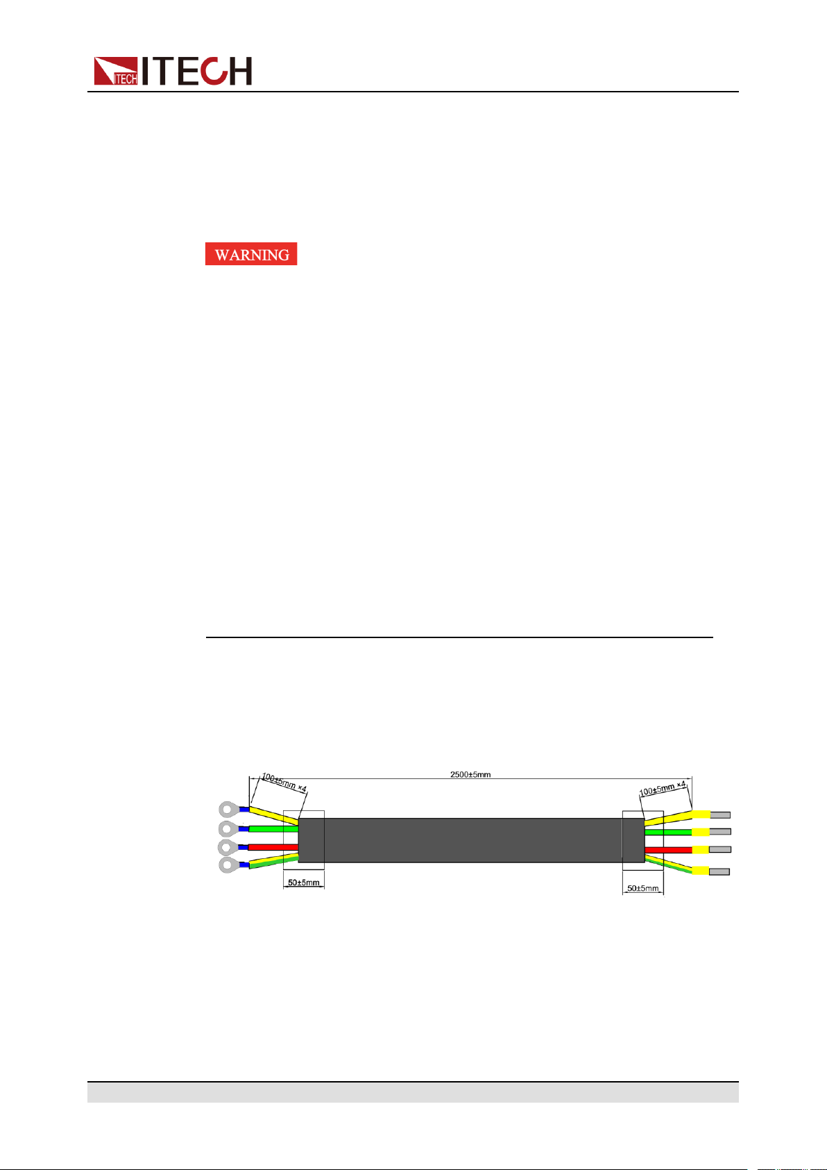
Categories of Power Cords
The power cord specifications of this series of instruments are as follows:
The red, green and yellow wires are live wires, which are correspondingly con-
nected to the L1, L2 and L3 terminals of power input on the rear panel of the instrument; the yellow-green wire is grounding wire, which is connected to the PE
terminal of power input on the rear panel.
Copyright © Itech Electronic Co., Ltd.
3
Page 15

AC Power Input Level
ООО "Техэнком" Контрольно-измерительные приборы и оборудование www.tehencom.com
The input of this series is a three-phase AC power of 380V. (Line voltage: such
as the voltage between L1 and L2).
• Voltage: 380V±10% (Three-phase four-wire)
• Frequency: 47Hz to 63Hz
Connecting the Power Cord
• For 3U model, see the steps below to connect the power cable.
• For units already assembled into a cabinet during ex-factory, if one end of
the power cable is connected, the user needs to connect the other end of
the power cable to the distribution box. The connection method is same as
that for the 3U model;
• For models to be assembled in parallel by the user, see contents related to
power cable connection in Cabinet Assembly Guide.
Inspection and Installation
1. Confirm that the switch of the AC power distribution box is off.
2. Confirm that the power switch is in the OFF position and verify that there is
no dangerous voltage on the connection terminals.
3. Remove the protective cover outside the AC input terminal on the rear
panel.
4. Connect one end of the power cable’s round terminal to the AC power input
terminal on the instrument’s rear panel.
a. You only need to connect the red, green and yellow live wires to the ter-
minals on the rear panel, which are not required to correspond to L1, L2
and L3 terminals one by one.
b. The yellow-green wire is grounding wire, which is connected to the pro-
tective grounding terminal (PE).
5. Mount the protective cover back to its original position.
6. Connect the other end of the power cable to the required AC distribution
box.
The schematic is shown below.
Copyright © Itech Electronic Co., Ltd.
4
Page 16

Inspection and Installation
ООО "Техэнком" Контрольно-измерительные приборы и оборудование www.tehencom.com
1.4 Connecting the Device Under Test (DUT)
Precautions
This section describes how to connect the test cables between the instrument
and DUT.
To prevent electric shock and damage to the instrument, observe the following
precautions.
Copyright © Itech Electronic Co., Ltd.
5
Page 17

Inspection and Installation
ООО "Техэнком" Контрольно-измерительные приборы и оборудование www.tehencom.com
• Before connecting test cables, be sure to switch off the instrument.
Power switch is in Off position, otherwise touching the output terminals
on the rear panel may result in personal injury or death due to electric
shock.
• To avoid electrical shock, before testing, please make sure the rating val-
ues of the testing cables, and do not measure the current that higher
than the rating value. All test cables shall be capable of withstanding the
maximum short circuit current of the instrument without causing
overheat.
• If several loads are provided, each pair of load wires shall safely with-
stand the rated short circuit output current of the power supply under full
load.
• Do not short the battery when connecting or disconnecting the battery
testing circuit. Short circuit may cause severe accident.
• Because the instrument can be used to sink current, hazardous voltages
from an external energy source such as a battery may be present on the
output terminals even with the instrument power off. Provision must be
made to disconnect the external energy source before touching the output or sense terminals.
• Always use test cables provided by ITECH to connect the equipment. If
test cables from other factories are used, please confirm the maximum
current that the test cables can withstand.
• During wiring, check that the positive and negative poles of the test ca-
bles are properly and tightly connected. Do not connect the positive pole
and disconnect the negative pole.
• Ensure that the output terminals are either insulated or covered using
the safety covers provided, so that no accidental contact with lethal voltages can occur.
Specification for Test Cables
Test cables are not standard accessories for the instrument. Please select op-
tional red and black test cables for individual sales based on the maximum current value. For specifications of test cables and maximum current values, refer
to A.1 Appendix→Specifications of Red and Black Test Lines.
Connecting the DUT (Local Measurement)
The instrument supports two kinds of wiring methods with the DUT: local measurement and remote measurement (SENSE). The default test mode is local
measurement.
The connection diagram and steps of local measurement are as follows:
Copyright © Itech Electronic Co., Ltd.
6
Page 18

Inspection and Installation
ООО "Техэнком" Контрольно-измерительные приборы и оборудование www.tehencom.com
1. Confirm that the power switch is in the OFF position and verify that there is
no dangerous voltage on the connection terminals.
2. Remove the output terminals cover of the power supply.
3. Loosen the screws of the output terminals and connect the red and black
test cables to the output terminals. Re-tighten the screws.
When maximum current that one test cable can withstand fails to meet the
rated current, use multiple pieces of red and black test cables. For example,
the maximum current is 1,200A, then 4 pieces of 360A red and black cables
are required.
4. Thread the red and black test cables through the output terminals cover of
the power supply and install the cover.
5. (Optional) According to the actual situation of DUT, connect the grounding
terminal on the rear panel of the instrument to the DUT to ensure the safe
grounding.
For the location information, see 2.3 Rear Panel Introduction.
6. Connect the other end of the red and black cables to the DUT. The positive
and negative poles must be properly connected and fastened when wiring.
Connecting the DUT (Remote Sensing)
Remote measurement is available for the following scenarios:
When the DUT consumes large current or the wires are too long, there is a voltage drop on the wires between DUT and output terminals of the power supply.
To maximize measurement accuracy, the power supply provides the remote
measurement terminals VS+ and VS- on the rear panel, which can be used to
measure the terminal voltage of the DUT.
When the power supply is used for battery testing in actual applications, the
voltage drop of the wire will lead to voltage inconsistency of both ends and inconsistency of the cutoff voltage of power supply and the actual voltage of bat-
tery, resulting in inaccurate measurement.
The connection diagram and steps of remote measurement are as follows:
Copyright © Itech Electronic Co., Ltd.
7
Page 19

Inspection and Installation
ООО "Техэнком" Контрольно-измерительные приборы и оборудование www.tehencom.com
1. Confirm that the power switch is in the OFF position and verify that there is
no dangerous voltage on the connection terminals.
2. Refer to the wiring diagram and connect the Vs+ and Vs- with armored
twisted-pair cables.
To ensure the stability of the system, use armored twisted-pair cables between the remote sense terminals and the DUT. Pay attention to the positive and negative poles when wiring, otherwise it will damage the
instrument.
3. Remove the output terminals cover of the power supply.
4. Loosen the screws of the output terminals and connect the red and black
test cables to the output terminals. Re-tighten the screws.
When maximum current that one test cable can withstand fails to meet the
rated current, use multiple pieces of red and black test cables. For example,
the maximum current is 1,200A, then 4 pieces of 360A red and black cables
are required.
5. Thread the red and black test cables through the output terminals cover of
the power supply and install the cover.
6. (Optional) According to the actual situation of DUT, connect the grounding
terminal on the rear panel of the instrument to the DUT to ensure the safe
grounding.
For the location information, see 2.3 Rear Panel Introduction.
7. Connect the other end of the remote sense cables to the DUT.
8. Connect the other end of the red and black cables to the DUT. The positive
and negative poles must be properly connected and fastened when wiring.
9. Power on the instrument and turn on the Sense function of the instrument.
For details, see 3.6.3 Sense Function (Sense).
Never touch cables or connections immediately after turning off the instrument at the end of the test. Lethal voltages may remain at the output terminals after turn-off. Verify that there is no dangerous voltage
on the output or sense terminals before touching them.
Copyright © Itech Electronic Co., Ltd.
8
Page 20

2 Quick Start
ООО "Техэнком" Контрольно-измерительные приборы и оборудование www.tehencom.com
This Chapter will introduce power-on check steps of this series to ensure normal
start-up and usage under initialization status of the power. Besides, to facilitate
usage, this part also displays the functions of front board, rear board and keyboard keys as well as display functions to a quick view of power appearance,
structure and key usage functions before operation.
♦ Brief Introduction
♦ Front-Panel Overview
♦ Rear Panel Introduction
♦ Power-on Self-Test
2.1 Brief Introduction
Quick Start
The IT6000C series Bi-directional Programmable DC Power Supply is designed
with the module concept. The voltage class of each module is 80V/200V/360V/
500V/800V. A single module can realize up to 800V/20A/6kW DC output capacity, and modules can be run in series or in parallel. At most of three modules
can be connected in series or in parallel for a single unit (3U) with input of three-
phase 380V AC power supply. The 3U model on sales supports 500V/90A/
18kW and 1500V/30A/18kW output to satisfy different test requirement such as
high current and low voltage or high voltage and low current. Meanwhile, units
can be run in parallel to deliver stronger output capacity.
In addition to the above powerful and diverse output capability, based on conventional features (such as List function, comprehensive protection and other
functions), the IT6000C series Bi-directional Programmable DC Power Supply
also supports a variety of unique features, such as digital I/O, data logging, energy regeneration, and the selective upgrade of system files. More functions,
technical indicators and technical innovations are described below:
• The standard 3U chassis of the IT6000C series instruments can accommo-
date up to 3 modules.
• Internal modules can be run in series or in parallel for voltage sharing or cur-
rent sharing.
• Single module output voltage ranges from 80V to 800V, and current ranges
from 20A to 170A.
• For the whole instrument, the output voltage ranges from 80V to 2250V, and
current ranges from 20A to 2040A.
Copyright © Itech Electronic Co., Ltd.
9
Page 21

Quick Start
ООО "Техэнком" Контрольно-измерительные приборы и оборудование www.tehencom.com
• The instrument supports bi-directional energy transmission and feeds elec-
tric energy back to the grid in a pollution-free manner, thus cutting electricity
and heat dissipation costs and meeting energy-saving and environmental
protection demands;
• It supports optional system file upgrade and one-click check of such informa-
tion as system version, module version and system configuration;
• Support List, battery test, comprehensive protection and parallel function.
• During the test, the instrument can record specific data type (such as voltage
value) and save it in the USB memory device;
• The front panel can be inserted with the USB memory device to support
such functions as system file upgrade, import/export of List files and data
record;
• Strong Digital I/O Function: In addition to general digital signal I/O functions,
it can also be customized by supporting the wiring through different pins to
meet different special needs through different pin wirings;
• Select CC loop priority or CV loop priority. If voltage and current parameters
are to be changed frequently during test, the user can directly set related parameters through [V-set] and [I-set] on the front panel, which is very
convenient;
• Built-in voltage curves comply with multiple automotive standards for quick
user recall.
• Built-in maximum power point tracking (MPPT) mechanism to provide solar
photovoltaic curve simulation.
• High visible vacuum fluorescent display (VFD)
• Support optical fiber communication, which is applicable for loop control be-
tween units under parallel mode.
• Built-in USB/CAN/LAN communication interface
• Optional GPIB/RS–232 communication interface
• Optional external analog interface, and share an interface position with RS-
232.
• Strong trigger system;
• Use a virtual resistor to realize paralleled current sharing and series voltage
sharing between units;
• Enable a true seamless switch between positive current and negative cur-
rent while avoiding overshoot current and overshoot voltage;
• When the Sense function is turned on, it can ensure that the DUT is safe in
case of reverse connection or open circuit of the Sense line.
Copyright © Itech Electronic Co., Ltd.
10
Page 22

The models included in the IT6000C series are as follows:
ООО "Техэнком" Контрольно-измерительные приборы и оборудование www.tehencom.com
Quick Start
500V 1,500V Height (with
bare machines
overlapped)
IT6006C-500-30 –
IT6012C-500-60 –
IT6018C-500-90 IT6018C-1500-30
IT6036C-500180
IT6054C-500270
IT6072C-500360
IT6090C-500-
450
IT6108C-500540
IT6036C-1500-60 6U
IT6054C-1500-90 9U 15U
IT6072C-1500120
IT6090C-1500-
150
IT6108C-1500180
3U
12U
15U 27U
18U
Height (constituting cabinet)
–
IT6126C-500630
IT6144C-500720
Naming rules for each series of model are as follows: IT 6XXXC-YYY-ZZZ,
wherein, XXX means rated power; YYY means rated voltage; and ZZZ
means rated current.
As a bipolar power supply, this series can output and absorb electric energy.
The current and power input capacity is same as the output capacity. For example, the maximum rated value of the output power of the IT6018C-500-90
model is 18,000W, and the maximum rated value of input power is also
18,000W.
IT6126C-1500210
IT6144C-1500240
2.2 Front-Panel Overview
For the IT6000C series Bi-directional Programmable DC Power Supply, all front
panels of the 3U model are the same, and the operation panels of other models
are the same as those of the 3U model. The following is the front panel schematic of the 3U model.
21U
24U
Copyright © Itech Electronic Co., Ltd.
11
Page 23

3U Model
ООО "Техэнком" Контрольно-измерительные приборы и оборудование www.tehencom.com
Quick Start
1 Power On/Off switch
2 Vacuum fluorescent display
(VFD)
3 Function and composite keys
4 Numeric and composite keys
2.2.1 Keyboard Introduction
The keyboard introduction of IT6000C series Bi-directional Programmable DC
Power Supply is shown as follows.
5 Up, down, left, and right cursor navigation
keys and Enter key
6 Push-on knob
7 Vent hole
8 USB storage device connection port
Table 2–1 Keys Description
Keys Description
[Esc] Press this key to exit the current operation interface.
[V-set] / Config Set the output voltage value / Enter the Config menu of
the power supply
Copyright © Itech Electronic Co., Ltd.
12
Page 24

Quick Start
ООО "Техэнком" Контрольно-измерительные приборы и оборудование www.tehencom.com
Keys Description
In CV priority (default) mode, press [V-set], the inter-
face displays “Vs=0.00V” (Setting value of voltage).
In CC priority mode, press [V-set], the interface dis-
plays “Vh=0.00V” (Upper limit of voltage), and press
[V-set] again, the interface displays “Vl=0.00V”
(Lower limit of voltage).
[I-set] / Function Set the output current value / Enter the Function menu
of the power supply
In CV priority (default) mode, press [I-set], the inter-
face displays “I+=0.00A” (Upper limit of current) ,
and press [I-set] again, the interface displays “I-= –
0.00 A” (Lower limit of current). In CC priority mode,
press [I-set], the interface displays “Is=0.00A” (Set-
ting value of current).
[P-set] / System Set the output power value / Enter the System menu
Press [P-set], the interface displays “P+=0.00W”
(Upper limit of power) , and press [P-set] again, the
interface displays “P- = – 0.00W” (Lower limit of
power) .
[Recall] / Protect Returns the instrument to the specified setup. / Enter the
Protect menu of the power supply
[Shift] Composite key, combined with other keys to realize func-
tions marked above keys.
[On/Off] / Trigger
• Turn the power supply output on or off. When lit, indi-
cates that the output is enabled or on.
• Generate a local trigger signal.
[0]-[9] Numeric keys
[Shift]+[1] (Log) Enter the data logging function menu.
[Shift]+[2] (Lock) Turn the keyboard lock on or off.
[Shift]+[3] (Local) Switch remote control mode to local control mode.
Copyright © Itech Electronic Co., Ltd.
13
Page 25

Keys Description
ООО "Техэнком" Контрольно-измерительные приборы и оборудование www.tehencom.com
Quick Start
[Shift]+[+/–]
(Save)
+/– Positive and negative signs
. Decimal point
Left / Right navigation keys
Up / Down navigation keys
[Enter] Operation confirmation key
2.2.2 Push-on Knob
The IT6000C series Bi-directional Programmable DC Power Supply provides a
knob on the front panel as shown in the next figure.
Save the common parameter settings.
The left and right navigation keys are used to adjust the
cursor to the specified position or scrolls pages to view
menu items.
The up and down navigation keys are used to scroll page
up and down to view menu items.
The functions of the posh-on knob is described as follows.
• Adjust the value setting
• Select menu item
• Confirm the set value or the selected menu item
Adjust the Value Setting
In the value setting interface, rotate the knob clockwise to increase the set value
and anticlockwise to decrease the set value.
Select Menu Item
The knob can also be used to view menu items. In the menu item display interface, turning the knob clockwise indicates that the next menu item is selected,
and turning the knob anticlockwise indicates that the previous menu item is
selected.
Copyright © Itech Electronic Co., Ltd.
14
Page 26

Confirm settings
ООО "Техэнком" Контрольно-измерительные приборы и оборудование www.tehencom.com
After completing the value setting or selecting a menu item, pushing the knob
acts like pressing [Enter] key to confirm the operation.
2.2.3 VFD Indicator Lamps Description
The IT6000C series Bi-directional Programmable DC Power Supply VFD indicator lamps description is as follows:
Table 2–2 VFD Indicator Lamps Description
Quick Start
Flag Function
Description
OFF The output of the
power supply is
turned off.
CV The power supply is
in a state of constant voltage
output.
CC The power supply is
in a state of con-
stant current output.
* The keyboard lock
is turned on.
CR None Rmt Indicates that the instrument
Flag Function Description
Auto None
Sense Sense function of the power
supply is enabled.
Rear Analog function begin to
work.
Addr When received command
successfully, the flag will display 3 seconds.
is working in remote control
mode.
Shift Using composite
function key
SRQ Indicates that the
internal status request event occurs.
CW The power supply is
in a state of con-
stant power output.
Copyright © Itech Electronic Co., Ltd.
Error Error occur
Prot The instrument enters the
protection state.
Trig The instrument is in a state
of waiting for a trigger.
15
Page 27

2.3 Rear Panel Introduction
ООО "Техэнком" Контрольно-измерительные приборы и оборудование www.tehencom.com
The rear panel of the 3U model of the IT6000C series Bi-directional Programmable DC Power Supply (after removing the protective cover) is shown below.
3U Models
1. Sense terminals (Vs+, Vs-)
Quick Start
2. DC output terminals of the power supply
3. Optional communication interface: RS-232 or GPIB
4. Digital I/O interface: P-IO
5. CAN communication interface
6. LAN communication interface
7. External control interface CTRL
This interface is used for cabinet self-assembling scenarios. Connect the
interface on the rear panel of each unit to be connected in parallel, and
the master can offer synchronous control over the power-on/off of the
slave.
8. USB communication interface
9. Communication interface of inner ring optical fiber (F-TX and F-RX)
This interface is used for cabinet self-assembling scenarios for realizing
communication of units in parallel.
10.Communication interface of outer ring optical fiber (TX and RX)
Copyright © Itech Electronic Co., Ltd.
16
Page 28

This interface is used for parallel scenarios of common units for the com-
ООО "Техэнком" Контрольно-измерительные приборы и оборудование www.tehencom.com
munication of units in parallel.
11. AC power input terminals (L1, L2, L3, and PE)
12.Chassis ground terminal
2.4 Power-on Self-Test
A successful self-test indicates that the purchased product meets delivery
standards and it is available for normal usage.
Before operation, please confirm that you have fully understood the safety
instructions.
Quick Start
• Before connecting power cord, be sure to confirm that the power voltage
matches with the rated input voltage of the instrument.
• Before connecting power cord, be sure to switch off the instrument. Veri-
fy that there is no dangerous voltage on the connection terminals.
• To avoid fire or electric shock, make sure to use the power cord supplied
by ITECH.
• Be sure to connect the power cord to the AC distribution box with protec-
tive grounding. Do not use terminal board without protective grounding.
• Do not use an extended power cord without protective grounding, other-
wise the protection function will fail.
• Be sure to perform related operations and connections to feed energy
back to grid in accordance with related regulations, and meet all necessary conditions.
• Ensure that the power cord connection terminals are either insulated or
covered by the supplied protective cover so that no accidental contact
with lethal voltage can occur.
Power Switch Introduction
User can adjust the power switch directly to turn on or turn off the instrument.
The status of Power switch is as follows.
Copyright © Itech Electronic Co., Ltd.
17
Page 29

Quick Start
ООО "Техэнком" Контрольно-измерительные приборы и оборудование www.tehencom.com
On Off On Off
If the instrument is the cabinet type, the rear panel of the cabinet provides a
master power switch. The relationships between the device status and switch
status are listed in the following table.
Master switch status Desperate switch
On On On
On Off Off
Off On Off
Off Off Off
Self-Test Procedures
Normal self-test procedures:
1. Correctly connect the power cord and power on the instrument.
The instrument starts the self-test.
2. After the instrument is self-tested normally, the VFD shows the output voltage, current, power and other information (CV mode).
If an error occurs during the self-test, an error message is displayed. The following table lists the error messages you might see.
Device status
status
Error message Error Description
Eeprom Failure The EEPROM is damaged.
Main FrameInitializeLost The system setting data is lost.
Calibration Data Lost The factory calibration data in EE-
PROM is lost.
Config Data Lost The latest operation state of the in-
strument is lost.
NETWORKING… The parallel operations are abnormal
and cannot finish the networking.
Copyright © Itech Electronic Co., Ltd.
18
Page 30

Exception Handling
ООО "Техэнком" Контрольно-измерительные приборы и оборудование www.tehencom.com
If the instrument cannot start normally, please check and take measures by
reference to steps below.
1. Check whether the power cord is correctly connected and confirm whether
the instrument is powered.
2. Check whether the power in On. The power switch is under “|” On status.
3. Check whether the power voltage matches with the supply voltage. Please
refer to 1.3 Connecting the Power Cord to select proper AC input.
4. If you need additional assistance, contact ITECH technical support engineer.
Quick Start
Copyright © Itech Electronic Co., Ltd.
19
Page 31

3 Basic Operation
ООО "Техэнком" Контрольно-измерительные приборы и оборудование www.tehencom.com
This chapter describes the basic functions and features of the instrument. Divided into the following sections:
♦ On/Off Control
♦ Local/Remote Mode Switch
♦ Key Lock Function
♦ Save and Recall Operations
♦ Data Logging Function
♦ System Menu Function
♦ System Upgrade
3.1 On/Off Control
Basic Operation
You can press the [On/Off] key on the front panel to control the output status of
the power supply. If the [On/Off] key light is on, indicates that the output is
turned on. If the [On/Off] key light is off, indicates that the output is turned off.
When the output of the power supply is on, the operating status flag (CV/CC/
CW) on the VFD will be illuminated.
It is recommended that you turn on the [On/Off] after the power supply is
connected to the DUT. If the power supply has no output after the output is
turned on, check the voltage and current setting value, set the voltage and
current to a non-zero value, and then turn on the output.
3.2 Local/Remote Mode Switch
The power supply provides both local and remote operation modes. The default
mode of the power supply is local operation mode.
• Local operation mode: Use the front panel keys to control the power supply.
• Remote operation mode: The power supply is connected to PC, and the user
uses the software in PC to control the power supply remotely.
– During remote control operation, the remote symbol “Rmt” is displayed.
All panel keys, except the [On/Off] and [Shift]+[3] (Local) keys, are
locked.
Copyright © Itech Electronic Co., Ltd.
20
Page 32

– You can press [Shift]+[3] (Local) to switch the remote control to local
ООО "Техэнком" Контрольно-измерительные приборы и оборудование www.tehencom.com
control. The mode modification will not affect the output parameters of
the power supply.
3.3 Key Lock Function
This function can prevent the power supply from the panel keys misoperation
during usage. Press the composite keys [Shift]+[2] (Lock) to lock front panel
keys and the lock symbol “*” is shown on the front panel display. All panel keys,
except the [On/Off] and [Shift]+[2] (Lock) keys, are locked. You can repress
[Shift]+[2] (Lock) to unlock the front panel.
3.4 Save and Recall Operations
Basic Operation
The power supply can save up to 10 common parameters in nonvolatile memory
(No. 1 to No. 10) for user to recall conveniently. The saved settings include the
following parameters.
Category Parameter
Main interface
Config menu CC/CV loop priority mode: Mode
Voltage setting: Vs
Current setting: Is
Upper limit of voltage: Vh, and lower limit of voltage: Vl
Upper limit of current: I+, and lower limit of current: I-
Upper limit of power: P+, and lower limit of power: P-
The output status of the instrument: [On/Off]
CC/CV loop speed: Speed
Voltage/Current rise time: V-Rise Time/I-Rise Time
Voltage/Current fall time: V-Fall Time/I-Fall Time
On/Off switch delay: On Delay/Off Delay
Internal resistance of the power supply: Output Res
Protect menu OCP/OVP/OPP/UCP/UVP switch status: On/Off
OCP/OVP/OPP/UCP/UVP limit setting: Level
Copyright © Itech Electronic Co., Ltd.
21
Page 33

Category Parameter
ООО "Техэнком" Контрольно-измерительные приборы и оборудование www.tehencom.com
You can do the save and recall operations by the following two methods.
• Press the composite keys [Shift]+[+/-] (Save) to save the parameters. Press
the [Recall] key to recall the parameters.
• SCPI commands: *SAV and *RCL
3.4.1 Save Operation
The save operation procedures are as follows:
1. Press the composite keys [Shift]+[+/-] (Save) to enter the parameter save
interface.
Basic Operation
OCP/OVP/OPP/UCP/UVP delay time: Delay
UCP/UVP warm-up time: Warm-up
2. Set the storage location.
Enter a number in the "Save data to bank=0" to set the storage location in
non-volatile memory.
3. Press [Enter] to save the parameters.
3.4.2 Recall Operation
You can recall the parameters you saved in the specified memory location as
the setting values.
1. Press the [Recall] key to enter the parameter recall interface.
2. Set the storage location.
Enter a number in the “Recall data from bank=0” to set the storage location
in non-volatile memory.
3. Press [Enter] to recall the parameters.
3.5 Data Logging Function
The IT6000C series Bi-directional Programmable DC Power Supply supports
the recording and saving of test data. This Chapter introduces how to use this
function in details.
Copyright © Itech Electronic Co., Ltd.
22
Page 34

The user can select the following data sources for recording:
ООО "Техэнком" Контрольно-измерительные приборы и оборудование www.tehencom.com
• Voltage
Only records voltage data during the data acquisition period.
• Current
Only records current data during the data acquisition period.
• Voltage and current
Records current and voltage data during the data acquisition period.
Configure the Function Menu
1. Press the composite button [Shift]+[1] (Log) on the front panel to enter the
configuration menu of the data logging function.
The parameters are described as follows:
Basic Operation
Menu Item Description Setting
Sample
Period
Duration This parameter indicates the time for
Source This parameter indicates the source
This parameter indicates the data
sampling interval (unit: s), that is, the
test data is recorded once every X
seconds.
The input range supported by the in-
strument is: 0 - 9
data recording (unit: s), namely, the
data recording will be completed in Y
seconds and be ready for the next
data record.
The input range supported by the in-
strument is: 0 - 3600
of recorded data, including voltage
(V), current (I), voltage and current
(V/I).
Set the value by in-
putting the value
through the number
key or rotating the
knob.
Use the Left and
Right arrow key or
the rotation knob to
select.
Copyright © Itech Electronic Co., Ltd.
23
Page 35

Basic Operation
ООО "Техэнком" Контрольно-измерительные приборы и оборудование www.tehencom.com
Menu Item Description Setting
Data Type This parameter indicates the type of
recorded data, including:
• Average: This is the default se-
lected data type, namely, the
average of all data acquired in the
data recording period as indicated
in the table of saved data.
• Max/Min: If this option is se-
lected, it means the maximum
value and minimum value of data
acquired in the data recording period as indicated in the data saving table.
2. Set the value of Sample Period and press [Enter].
3. Set the value of Duration and press [Enter].
4. Set the value of Source and press [Enter].
5. Set the value of Data Type and press [Enter].
At this point, the VFD screen returns to the main interface of the system.
Select the Trigger Method
See the steps in the 3.6.4 Select Trigger Source (Trig Source) section to set
how the data logging is triggered.
This setting result is only valid for data recording function. When List function
is used, the method for triggering the running of List files needs to be addi-
tionally set (by default, triggered by the panel).
Copyright © Itech Electronic Co., Ltd.
24
Page 36

Start Data Logging
ООО "Техэнком" Контрольно-измерительные приборы и оборудование www.tehencom.com
• Manual
• Bus
Basic Operation
Before this operation, make sure to connect the USB memory device
to the memory port on the front panel (The USB interface on the rear
panel can only be used for connecting the PC) so that the recorded
data can be stored in the external storage device. Otherwise, the Data
Recording function is not available for usage.
Press the composite button [Shift] + [On/Off] (Trigger) on the front panel to
trigger.
Triggered by the SCPI instruction, for example, when the instrument receives the trigger command *TRG, a trigger operation is performed.
• External
Connect to pin 4 of the digital I/O interface (P-IO) and set pin 4 to Ext-Trig→Trig-In→Dlog to trigger.
For details, see 3.6.7.4 IO–4. Ext-Trig, Not-Invert.
After the data recording function is started, the lower right corner of the main interface displays Logging, indicating that the data is recorded. The recorded data is saved in USB memory device in .csv format. The user can get access to
these files for analysis based on needs.
3.6 System Menu Function
This Chapter offers a general introduction of system menus, allowing users to
have a preliminary understanding of system functions of this IT6000C series.
The steps of the system menu function are as follows:
1. Press the composite keys [Shift]+[P-set] (System) on the front panel to enter the system menu.
At this point, the VFD screen displays the system menu items. Each menu
item has a numbering identifier. The user can press Up and Down buttons or
use the knob for scrolling display of other menu items.
2. Press [Enter] on a menu interface to enter the setting interface.
Copyright © Itech Electronic Co., Ltd.
25
Page 37

3. After the menu items are set, press [Enter] again to save the modified
ООО "Техэнком" Контрольно-измерительные приборы и оборудование www.tehencom.com
contents.
The description of the menu items is shown in the table below.
System System Menu
Beep Set the beeper state.
Basic Operation
You can press [Esc] to return to the previous menu.
Turn the beeper on.
Turn the beeper off.
PowerOn
On
Off
Select the power-on state.
When the instrument is powered on, the instru-
Reset
ment will initialize some settings and [On/Off]
state.
When the instrument is powered on, the instru-
Last
ment will remain the same settings and
[On/Off] state as last time you turned off the
instrument.
When the instrument is powered on, the instru-
Last+Off
ment will remain the same settings as last time
you turned off the instrument, but the [On/Off]
is OFF state.
Sense Set the sense function state.
Off Turn the sense function off.
On Turn the sense function on.
ListTrig Source Set the trigger method for the List files running.
DataLogger Trig
Source
I/O Con
Manual
Bus
External
Manual trigger
Bus trigger
External trigger
Set the trigger method for the data logging.
Manual
Bus
External
Manual trigger
Bus trigger
External trigger
Set the communication information between instrument and
PC.
USB USB communication interface
LAN LAN communication interface
Copyright © Itech Electronic Co., Ltd.
26
Page 38

Basic Operation
ООО "Техэнком" Контрольно-измерительные приборы и оборудование www.tehencom.com
Info View the LAN information.
LAN Status: Down
IP Mode: Disconnect
IP Addr: 0.0.0.0
SubNet: 0.0.0.0
Gateway: 0.0.0.0
DNS1: 0.0.0.0
DNS2: 0.0.0.0
MAC: 8C:C8:F4:40:01:E1
MDNS Status:
HostName:
HostDesc:
Domain:
TCPIP::INSTR:
Socket Port: 30000
IP-Conf
Configure LAN IP information.
Auto: automatically configure the
address of the instrument.
Manual: manually configure the address of the instrument.
• IP Addr: 0.0.0.0
Set the IP address.
• SubNet: 0.0.0.0
Set the subnet mask.
• Gateway: 0.0.0.0
Set the gateway address.
• DNS1: 0.0.0.0
Set the preferred address of the
DNS server. If it is not involved,
there is no need to set it.
• DNS2: 0.0.0.0
Set the DNS server alternate
address. If it is not involved,
there is no need to set it.
• Socket Port: 30000
Set the port number.
ServConf
Configure the LAN services.
MDNS: MDNS service state.
• On
• Off
PING: PING service state.
• On
Copyright © Itech Electronic Co., Ltd.
27
Page 39

Basic Operation
ООО "Техэнком" Контрольно-измерительные приборы и оборудование www.tehencom.com
• Off
Telnet-scpi: telnet-scpi service
state.
• On
• Off
Web: Web service state.
• On
• Off
VX-11: VX-11 service state.
• On
• Off
Raw-socket: Raw-socket service
state.
• On
• Off
Reset
CAN CAN communication interface.
Baudrate
Address
Prescal-erPrescale
BS1
Value
BS2
Value
VCP Select virtual serial communication interface.
Baudrate
Databit Data bit: 5/6/7/8
Select whether to confirm the LAN
setting or not.
Select the baud rate from the following options: 20k, 40k, 50k, 80k,
100k, 125k, 150k, 200k, 250k,
400k, 500k, 1000k.
Set the instrument address to a
number from 1 to 65535.
PTS
PBS
Baud rate: 4800/9600/19200/
38400/57600/115200
Parity
Stopbit Stop bit: 1/2
Display RS232
or GPIB according to optional interface. In
addition, RS232
RS232 Select RS-232 communication interface.
Baudrate
Databit Data bit: 5/6/7/8
Copyright © Itech Electronic Co., Ltd.
Parity bit: N (No parity) / E (Even
parity) / O (Odd parity)
Baud rate: 4800/9600/19200/
38400/57600/115200
28
Page 40

Basic Operation
ООО "Техэнком" Контрольно-измерительные приборы и оборудование www.tehencom.com
interface and the
analog interface
share an interface position.
Parallel
Digital Port
Parity
Stopbit Stop bit: 1/2
GPIB Select GPIB communication interface.
Address
Set the instruments to parallel operation mode.
Single
Master Set the instrument to master mode.
Slave Set the instrument to slave mode.
Set Digital I/O
By default, the menu item displays 7 options. You can set
parameters for each option respectively. After setting, the
corresponding change to each option becomes valid immediately. When re-entering DigPort, the interface can display
the changed option. For detailed introduction of menus and
functions, see 3.6.7 Digital I/O Function (Digital Port).
Set the instrument to single mode, i.e., disable
the parallel operation mode.
Total: Number of parallel instruments.
Parity bit: N (No parity) / E (Even
parity) / O (Odd parity)
Set the communication address (1
to 30).
IO-1. Ps-Clear, NotInvert
IO-2. Ps, Not-Invert
IO-3. Off-Status, NotInvert
IO-4. Ext-Trig, NotInvert
IO-5. INH-Living, NotInvert
IO-6. Sync-On, NotInvert
IO-7. Sync-Off, NotInvert
External Analog Function. This function is optional. The
Ext-Program
System Reset Select whether to restore the factory default settings or not.
System Info View the system information.
menu can only display when corresponding board card is inserted. For detailed menu settings, see 3.6.8 (Optional)
Analogue Function (Ext-Program).
Function setting of pin 1
Function setting of pin 2
Function setting of pin 3
Function setting of pin 4
Function setting of pin 5
Function setting of pin 6
Function setting of pin 7
Model
MAC Addr
SN
Copyright © Itech Electronic Co., Ltd.
Display the instrument model.
Display the MAC address, that is, the physical
address.
Display the serial number.
29
Page 41

Basic Operation
ООО "Техэнком" Контрольно-измерительные приборы и оборудование www.tehencom.com
Main-Ver Display the system version information.
Ctrl-Ver Display the version information for a single
module.
FPGA-Ver Display the FPGA version information.
INV-Ver Display the control board version information.
2017/6/22
00:00:00
Press the composite button [Shift]+[P-set] (System) to enter the system
menu, and press [Esc] to exit the menu.
Display the system time.
3.6.1 Set the Beeper Status (Beep)
The user can turn the instrument beeper sound on or off base on personal
requirement.
The beeper sound works in the following scenarios:
• A beeper sound produced when the front panel key is pressed.
• When an error is generated inside the instrument, such as when the instru-
ment receives an unprocessable command in the remote state. At this time,
the instrument produces a beeper sound, and the flag “Error” appears on the
VFD.
• When the instrument is under protection status, such as over-temperature
protection. At this time, the instrument produces the beeper sound.
The setting procedures are as follows:
1. Press the composite keys [Shift]+[P-set] (System) on the front panel to enter the system menu.
The first displayed menu item Beep is used to set the beeper status.
2. Press [Enter] key to enter the parameter setting interface.
3. Press the Left / Right key or turn the knob to adjust the value of this
parameter.
• On: Default value, indicates the beeper is on.
• Off: Indicates the beeper is off.
4. After the parameter settings are complete, press [Enter].
At this point, the beeper status takes effect immediately.
Copyright © Itech Electronic Co., Ltd.
30
Page 42
3.6.2 Set the Power-on State (PowerOn)
ООО "Техэнком" Контрольно-измерительные приборы и оборудование www.tehencom.com
This menu item is used to control the settings and output state when the power
supply is powered on.
The detailed power-on parameters and output state are as follows.
• The voltage, current, power setting values displayed on the main interface
when the instrument is powered on.
• Parameter setting values in the Config and Protect menus.
• The output state of the power supply, i.e., the [On/Off] key state.
The procedures to set the menu item are as follows.
1. Press the composite keys [Shift]+[P-set] (System) on the front panel to enter the system menu.
2. Press the Up/Down key or turn the knob to select the [PowerOn] and press
[Enter].
Basic Operation
3. Press the Left / Right key or turn the knob to adjust the value of this
parameter.
• Reset: Default value, indicates when the instrument is powered on, the
instrument will initialize some parameter settings or state.
The affected parameters and the reset information are as shown in Table
3–1 Initial value of the parameter.
Table 3–1 Initial value of the parameter
Category Parameter Initial Value
Main
interface
Voltage setting: Vs One percent of the
rated voltage of the
instrument
Current setting: Is One percent of the
rated current of the
instrument
Upper limit of voltage: Vh, and
lower limit of voltage: Vl
Upper limit value: One
percent of the rated
voltage of the
instrument
Lower limit value: 0
Upper limit of current: I+, and
lower limit of current: I-
Copyright © Itech Electronic Co., Ltd.
One percent of the
rated current of the
instrument
31
Page 43

Basic Operation
ООО "Техэнком" Контрольно-измерительные приборы и оборудование www.tehencom.com
Category Parameter Initial Value
Config
menu
Upper limit of power: P+, and
lower limit of power: P-
[On/Off] status Off
Mode CV
Speed High
V-Rise Time/I-Rise Time 0.1s
V-Fall Time/I-Fall Time
Output Res 1000
On Delay/Off Delay 0
Rated power value of
the instrument
• Last: Indicates when powered on, the instrument will remain the same
parameter settings (i.e., the parameters controlled by the *SAV 0 command, see 3.4 Save and Recall Operations) as last time you turned off
the instrument.
• Last+Off: Indicates when powered on, the instrument will remain the
same settings as last time you turned off the instrument, but the output
state is Off.
Under the condition of Last+Off, the output switch state is not con-
strained by the *SAV 0 instruction.
4. After the parameter settings are complete, press [Enter].
For example, Last is selected, and the voltage value is set to 20V. After the
instrument is powered off and then powered on, the voltage displayed on the
interface is 20V.
3.6.3 Sense Function (Sense)
This menu item is used to switch the power supply to local measurement or remote sensing.
The IT6000C series power supply supports two connection methods: Local
measurement and Remote sensing. The remote sensing is used for maximizing
measurement accuracy. (Refer to 1.4 Connecting the Device Under Test (DUT))
The procedures to set the menu item are as follows.
Copyright © Itech Electronic Co., Ltd.
32
Page 44

1. Press the composite keys [Shift]+[P-set] (System) on the front panel to en-
ООО "Техэнком" Контрольно-измерительные приборы и оборудование www.tehencom.com
ter the system menu.
2. Press the Up/Down key or turn the knob to select the Sense and press
[Enter].
3. Press the Left / Right key or turn the knob to adjust the value of this
parameter.
• Off: Default value, indicates turn the sense function off.
• On: Indicates turn the sense function on.
4. After the parameter settings are complete, press [Enter].
3.6.4 Select Trigger Source (Trig Source)
For the IT6000C series power supply, the List and data logging functions can be
triggered for running by the following methods:
Basic Operation
• Manual: Default value, indicates the trigger occurs when the
[Shift]+[On/Off] (Trigger) keys are pressed from the front panel.
• Bus: Indicates the trigger occurs via the communication cables. When the
trigger command *TRG is received, the IT6000C instrument generates a
trigger.
• External: Indicates the trigger occurs via the pin 4 of the digital I/O interface
(P-IO).
For details, see 3.6.7.4 IO–4. Ext-Trig, Not-Invert.
The List function and the data logging function have the same steps for selecting the trigger source. They need to be set separately in different menu items
(ListTrig Source and DataLogger Trig Source). Therefore, this section takes
the List trigger source setting as an example to introduce the operation steps.
1. Press the composite keys [Shift]+[P-set] (System) on the front panel to enter the system menu.
2. Press the Up/Down key or turn the knob to select the ListTrig Source and
press [Enter].
• When setting the trigger source for data logging, select the
DataLogger Trig Source menu item.
• The List trigger source set here is also valid for triggering other functions in
the Function menu.
Copyright © Itech Electronic Co., Ltd.
33
Page 45

Basic Operation
ООО "Техэнком" Контрольно-измерительные приборы и оборудование www.tehencom.com
3. Press the Left / Right key or turn the knob to adjust the value of this
parameter.
4. After the parameter settings are complete, press [Enter].
3.6.5 Set the Communication Information (I/O Con)
This menu item is used to set the communication information between instrument and PC. The standard communication interfaces for IT6000C series power
supply are USB, LAN, CAN and VCP. You can also select the non-standard interface GPIB or RS-232 based on personal requirement.
The procedures to set the menu item are as follows.
1. Press the composite keys [Shift]+[P-set] (System) on the front panel to enter the system menu.
2. Press the Up/Down key or turn the knob to select the I/O Con and press
[Enter].
3. Press the Left / Right key or turn the knob to adjust the value of this
parameter.
4. After the parameter settings are complete, press [Enter].
• The default communication method is USB. If other communication method
is selected, the related parameters need to be set. For detailed parameter
description, refer to 5 Remote Interface Connection.
• The instrument supports the non-standard RS-232 and GPIB interfaces, and
the configuration items in the menu are dynamically displayed according to
the interface user selected.
3.6.6 Set Parallel Operation Mode (Parallel)
This menu item is used to control whether the instrument is working in single
mode or in parallel mode. This chapter takes three instruments as an example
to describe how to parallelize the single units and how to return from parallel
mode to single mode.
The IT6000C series power supply supports multiple instruments to work in parallel mode to provide more power and current output capability.
Configure the Menu Item
1. Press the composite keys [Shift]+[P-set] (System) on the front panel to en-
ter the system menu.
Copyright © Itech Electronic Co., Ltd.
34
Page 46
Basic Operation
ООО "Техэнком" Контрольно-измерительные приборы и оборудование www.tehencom.com
2. Press the Up/Down key or turn the knob to select the Parallel and press
[Enter].
3. Press the Left / Right key or turn the knob to adjust the value of this
parameter.
• Single: Default value, indicates that the instrument is in single mode.
• Master: Indicates that the current single unit is set to master in parallel
mode. When set to Master, you also need to set the number of slaves to
be mounted for the master, so you need to set the value of the Total pa-
rameter. For example, setting Total = 3 means that the total number of
units in the parallel relationship is 3.
In the parallel mode, you only need to operate the master. Synchro-
nous operations on other slaves are implemented by operating the
master.
• Slave: Indicates that the instrument is set to the slave in parallel mode.
4. After the parameter settings are complete, press [Enter].
Set the Parallel Mode
For 3U models, up to 8 units of the same model can be connected in parallel.
Taking three 3U single instruments as an example, the steps for parallel operation are as follows.
Before connecting the system bus, you must ensure that each instrument is in single mode (Single).
Before connecting the cables, ensure that the instrument power switch
is off and the main of the AC power input (380V distribution box) is off.
1. Ensure that the power switches of the three units and the main switch of the
AC power distribution box are off.
2. Refer Figure 3–1 Wiring connection diagram to connect three units.
Copyright © Itech Electronic Co., Ltd.
35
Page 47
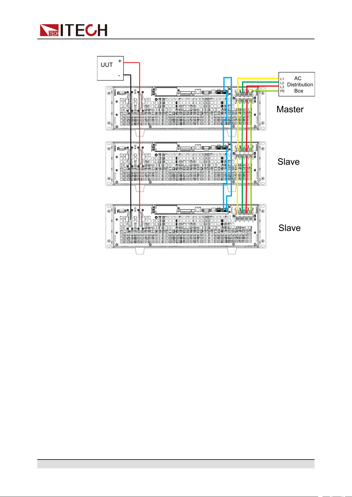
Figure 3–1 Wiring connection diagram
ООО "Техэнком" Контрольно-измерительные приборы и оборудование www.tehencom.com
Basic Operation
a. Connect the AC input terminals of the three units in parallel and connect
them to the AC distribution box.
b. Connect the DC output terminals of the three units in parallel and connect
them to the DUT.
c. Refer to the blue wiring legend in the figure, connect the System Bus (i.
e., the fiber outer loop interfaces TX and RX) for fiber-optic communication between the master and slaves.
3. Turn on the main switch of the AC distribution box and power on each of the
three units.
4. Set three units in parallel mode with one master and two slaves.
a. Press the composite keys [Shift]+[P-set] (System) on the front panel to
enter the system menu.
b. Set Parallel to Master or Slave and press [Enter].
c. After setting the Master, you need to set Total to 3.
For details, see Configure the Menu Item.
5. After the parallel menu of the three units are set, restart the instrument
separately.
After the instrument is restarted, the VFD shows that the instrument is working in parallel mode.
Copyright © Itech Electronic Co., Ltd.
36
Page 48

Revert to Single Mode
ООО "Техэнком" Контрольно-измерительные приборы и оборудование www.tehencom.com
1. Power off the three instruments and turn off the main switch of the AC distribution box.
2. Remove the cables connection of the System Bus and DC output terminals
between three units.
3. Power on the three instruments separately.
4. Set each of the three instruments to single mode.
a. Press the composite keys [Shift]+[P-set] (System) on the front panel to
enter the system menu.
b. Set the Parallel to Single.
For details, see Configure the Menu Item.
5. Restart the three instruments separately.
After the instrument is restarted, the VFD shows that the instrument is working in single mode.
3.6.7 Digital I/O Function (Digital Port)
Basic Operation
The IT6000C series power supply supports digital I/O function. The user can
realize logic control over high and low level input or output by related configurations in the system menu, namely general digital signal I/O function. In addition
to general digital I/O functions, this series can be customized to meet different
special needs through different pin wirings. For example, you can connect a pin
to an external instrument, and set a fixed pulse or level signal for the external instrument. Once the external instrument fails, output this pulse or level signal.
After the instrument identifies this signal, it controls whether the power supply
output is reduced to 0 or whether the [On/Off] is switched off based on related
settings.
The rear panel of the instrument has a green 8-pin terminal (For position, see
2.3 Rear Panel Introduction). The terminal is a wiring terminal with digital I/O
function. These pins are bi-directional I/O interfaces. For hardware index information, see Table 3–2 Hardware parameters of the I/O interface. The pins sup-
port the input or output of pulse and high and low level. Different pins can
achieve different functions.
Table 3–2 Hardware parameters of the I/O interface
Voltage range -5V to +15V
Low Level (V) Maximum current
Maximum low level output
voltage
Copyright © Itech Electronic Co., Ltd.
0.65 10
0.9 50
(mA)
37
Page 49

1 100
ООО "Техэнком" Контрольно-измерительные приборы и оборудование www.tehencom.com
Basic Operation
Pins Introduction
The appearance of the terminals are shown below.
Maximum low level input
voltage
Typical high level output
voltage
Typical low level current 0V 0.5mA
Minimum high level input
voltage
Level rise slope 10us
Level fall slope 2us
0.8V
5V
1.6V
Pin Description Properties
(Default
function)
1 Corresponds to the function set in the
System→Digital Port→IO–1. PsClear, Not-Invert menu item. For pa-
rameter introduction, see 3.6.7.1 IO–
1. Ps-Clear, Not-Invert.
2 Corresponds to the function set in the
System→Digital Port→IO–2. Ps,
Not-Invert menu item. For parameter
introduction, see 3.6.7.2 IO–2. Ps,
Not-Invert.
3 Corresponds to the function set in the
System→Digital Port→IO–3. Off-
Status, Not-Invert menu item. For
Pulse signal Level or PWM
Level signal Level or PWM
Level signal Level or PWM
Properties
(General I/O
function)
signal
signal
signal
Copyright © Itech Electronic Co., Ltd.
38
Page 50

Basic Operation
ООО "Техэнком" Контрольно-измерительные приборы и оборудование www.tehencom.com
Pin Description Properties
(Default
function)
parameter introduction, see 3.6.7.3
IO–3. Off-Status, Not-Invert.
4 Corresponds to the function set in the
Pulse signal Level or PWM
System→Digital Port→IO–4. ExtTrig, Not-Invert menu item. For pa-
rameter introduction, see 3.6.7.4 IO–
4. Ext-Trig, Not-Invert.
5 Corresponds to the function set in the
Pulse signal Level or PWM
System→Digital Port→IO–5. INHLiving, Not-Invert menu item. For
parameter introduction, see 3.6.7.5
IO–5. INH-Living, Not-Invert.
6 Corresponds to the function set in the
Pulse signal Level or PWM
System→Digital Port→IO–6. SyncOn, Not-Invert menu item. For pa-
rameter introduction, see 3.6.7.6 IO–
6. Sync-On, Not-Invert.
Properties
(General I/O
function)
signal
signal
signal
7 Corresponds to the function set in the
System→Digital Port→IO–7. Sync-
Pulse signal Level or PWM
signal
Off, Not-Invert menu item. For parameter introduction, see 3.6.7.7 IO–
7. Sync-Off, Not-Invert.
GND Ground terminal, that is, the negative
Level signal
terminal corresponding to each of the
above 7 pins.
In this chapter, all the pulse signals involved in the digital I/O function are
switched from high level to low level.
Taking pin 1 as an example, IO–1. Ps-Clear, Not-Invert contains three function
options, the first option Ps-Clear is the default function, and this function is also
a special custom function unique to this pin (the seven pins each have a different custom function). The second and third options (Input and Output) are the
general digital I/O function, and the parameter settings and functions of the seven pins are the same.
Copyright © Itech Electronic Co., Ltd.
39
Page 51

General Digital I/O Function
ООО "Техэнком" Контрольно-измерительные приборы и оборудование www.tehencom.com
• Under the default condition (Not-Invert), when the pin (1 to 7) is configured
as Output, it can output the high level (False) or low level (True).
If the corresponding pin is configured as Invert, it means that the digital
signal is inverted and will output low level or high level.
• Under the default condition (Not-Invert), when the pin (1 to 7) is configured
as Output→PWM, the user needs to set the frequency (PWM Freq) and duty cycle (PWM Duty) values. For example, if the PWM Freq is set to 100Hz
and the PWM Duty is set to 10%, the output waveform is as follows:
Basic Operation
In the above figure, the peak voltage (minimum value) is 5.16V and the
cycle is 10ms. The high level duration is 9ms and the low level duration is
1ms in one cycle.
• Under the default condition (Not-Invert), when the pin (1 to 7) is configured
as Input, it means the instrument can detect the level status of the external
input. By default (i.e., the pin is not connected), it can be detected as high
level, and the front panel will display input(0). If the pin is configured as
Invert, it can be detected as low level, and the front panel will display input
(1).
Copyright © Itech Electronic Co., Ltd.
40
Page 52

3.6.7.1 IO–1. Ps-Clear, Not-Invert
ООО "Техэнком" Контрольно-измерительные приборы и оборудование www.tehencom.com
Parameter Description
Basic Operation
IO–1. Ps-Clear,
Not-Invert
Parameter setting for pin 1.
NotInvert
Invert
Indicates whether to invert the input/output
pulse or level signal.
• Invert: Yes
• Not-Invert: No
PsClear
Input Pin 1 receives the level signal from
Output Pin 1 sends the digital signal (1, 0,
This default function means that when
the instrument generates protection,
the protection state can be cleared via
this pin.
the outside.
PWM) to the outside.
True By default (Not-Invert), the
output digital signal is 1 (i.e.
low level), and in the case of
Invert, the output is high
level.
How to Use
False By default (Not-Invert), the
output digital signal is 0 (i.e.
high level), and in the case of
Invert, the output is low level.
PWM Digital signal of PWM.
PWM Freq Frequency
PWM Duty Duty cycle
When pin 1 is set to default Ps-Clear function, pin 1 has bi-directional I/O function, which can receive pulse signal input from the external instrument and also
can output pulse signal to external instrument. Pulse signal parameter requirements are as follows:
Copyright © Itech Electronic Co., Ltd.
41
Page 53

Level rise slope 10us
ООО "Техэнком" Контрольно-измерительные приборы и оборудование www.tehencom.com
Level fall slope 2us
Basic Operation
Minimum time width
for low level keep
30us
• Pulse input: When the instrument is under protection, the instrument will
clear protection after receiving the pulse signal from external input.
1. Refer to the figure below to connect pin 1 to the external oscilloscope.
2. Confirm that pin 1 function is set to the default option, namely
IO-1. Ps-Clear, Not-Invert.
3. Taking OVP as an example, set the protection point of OVP.
4. Build the test environment to enable the instrument to enter the OVP
state.
5. Send pulse signal to pin 1.
6. Check whether the protection state of this instrument is cleared.
• Pulse output: When the instrument’s protection state is released, and
[On/Off] is from Off to On, pin 1 will send a pulse signal to the external
instrument.
1. After confirming that the instrument’s OVP protection is cleared, manually turn on [On/Off].
2. Check the oscilloscope and confirm whether pin 1 has pulse output.
Copyright © Itech Electronic Co., Ltd.
42
Page 54
3.6.7.2 IO–2. Ps, Not-Invert
ООО "Техэнком" Контрольно-измерительные приборы и оборудование www.tehencom.com
Parameter Description
Basic Operation
IO–2. Ps, NotInvert
Parameter setting for pin 2.
NotInvert
Invert
Indicates whether to invert the input/output
pulse or level signal.
• Invert: Yes
• Not-Invert: No
Ps This default function means the output
level from pin 2, which displays that
whether the instrument is under pro-
tection or not.
Input Pin 2 receives the level signal from
the outside.
Output Pin 2 sends the digital signal (1, 0,
PWM) to the outside.
True By default (Not-Invert), the
output digital signal is 1 (i.e.
low level), and in the case of
Invert, the output is high
level.
How to Use
False By default (Not-Invert), the
output digital signal is 0 (i.e.
high level), and in the case of
Invert, the output is low level.
PWM Digital signal of PWM.
PWM Freq Frequency
PWM Duty Duty cycle
When pin 2 is set to default Ps function, pin 2 will output high or low level based
on whether the instrument is under protection or not. Under normal conditions
(Not under protection), and when pin 2 is under default setting (Not-Invert), pin
2 outputs high level; when the instrument is under protection, pin 2 outputs low
level.
Copyright © Itech Electronic Co., Ltd.
43
Page 55

Basic Operation
ООО "Техэнком" Контрольно-измерительные приборы и оборудование www.tehencom.com
When pin 2 is set to Invert, the output level is completely opposite.
1. Refer to the figure below to connect pin 2 to the external oscilloscope.
2. Confirm that pin 2 function is set to the default option, namely
IO-2. Ps, Not-Invert.
3. Taking OVP as an example, set the protection point of OVP.
4. Build the test environment to enable the instrument to enter the OVP state.
5. Check the oscilloscope and confirm that pin 2 outputs low level.
3.6.7.3 IO–3. Off-Status, Not-Invert
Parameter Description
IO–3. Off-Status, Not-Invert
Parameter setting for pin 3.
NotInvert
Invert
Indicates whether to invert the input/output pulse
or level signal.
• Invert: Yes
• Not-Invert: No
OffStatus
Input Pin 3 receives the level signal from the
Copyright © Itech Electronic Co., Ltd.
This default function indicates the existing [On/Off] state of the instrument.
outside.
44
Page 56

Basic Operation
ООО "Техэнком" Контрольно-измерительные приборы и оборудование www.tehencom.com
Output Pin 3 sends the digital signal (1, 0, PWM)
to the outside.
True By default (Not-Invert), the out-
put digital signal is 1 (i.e. low level), and in the case of Invert, the
output is high level.
False By default (Not-Invert), the out-
put digital signal is 0 (i.e. high
level), and in the case of Invert,
the output is low level.
PWM Digital signal of PWM.
PWM Freq Frequency
PWM Duty Duty cycle
How to Use
When pin 3 is set to default Off-Status function, pin 3 will trigger level output
based on the [On/Off] state of the instrument. When it is set to (Not-Invert), the
[On/Off] is turned off, and pin 3 outputs high level; the[On/Off] is turned on, and
pin 3 outputs low level.
When pin 3 is set to Invert, the output level is completely opposite.
1. Refer to the figure below to connect pin 3 to the external oscilloscope.
Copyright © Itech Electronic Co., Ltd.
45
Page 57

2. Confirm that pin 3 function is set to the default option, namely
ООО "Техэнком" Контрольно-измерительные приборы и оборудование www.tehencom.com
IO-3. Off-Status, Not-Invert.
3. Turn on [On/Off].
4. Check the oscilloscope and confirm that pin 3 outputs low level.
3.6.7.4 IO–4. Ext-Trig, Not-Invert
Parameter Description
Basic Operation
IO–4. ExtTrig, NotInvert
Parameter setting for pin 4.
NotInvert
Invert
Indicates whether to invert the input/output pulse or
level signal.
• Invert: Yes
• Not-Invert: No
Ext-Trig This default function means that pin 4 of
the P-IO performs bi-direction control over
the instrument’s trigger function.
Trig–Out Indicates that when the instru-
Trig-In Indicates that the instrument
ment generates a signal (which
triggers the Meter function, Data Recording function and List
function for running), pin 4 will
output a pulse signal.
will trigger the running of one of
the functions below after receiving the external pulse signal.
Meter Triggers the run-
ning of Meter
function. This
function needs to
be triggered at
the upper computer side
through SCPI instruction. For details, refer to
Copyright © Itech Electronic Co., Ltd.
46
Page 58

Basic Operation
ООО "Техэнком" Контрольно-измерительные приборы и оборудование www.tehencom.com
instructions related to ACQuire
in the Trigger
subsystem of the
Instruction
Manual.
Dlog Triggers the run-
ning of data recording function.
List Triggers the run-
ning of List files.
Input Pin 4 receives the level signal from the
outside.
Output Pin 4 sends the digital signal (1, 0, PWM)
to the outside.
How to Use
True By default (Not-Invert), the out-
put digital signal is 1 (i.e. low
level), and in the case of Invert,
the output is high level.
False By default (Not-Invert), the out-
put digital signal is 0 (i.e. high
level), and in the case of Invert,
the output is low level.
PWM Digital signal of PWM.
PWM Freq Frequency
PWM Duty Duty cycle
Taking the triggering of List function as an example, the text below will introduce
how to use pin 4’s default function Ext-Trig.
• Trig–Out
1. Refer to the figure below to connect pin 4 to the external oscilloscope.
Copyright © Itech Electronic Co., Ltd.
47
Page 59

Basic Operation
ООО "Техэнком" Контрольно-измерительные приборы и оборудование www.tehencom.com
2. Set pin 4’s function to Not-Invert and Trig-Out.
3. Recall the edited List file for trigger running.
4. Press [Shift]+[On/Off] (Trigger) on the front panel to trigger the running
of List files.
ListTrig Source is set to Manual.
5. Check the oscilloscope and confirm whether pin 4 has following pulse
signal output.
Level rise slope 10us
Level fall slope 2us
Minimum time width
for low level keep
30us
• Trig-In
1. Refer to the figure below to connect pin 4 to the external oscilloscope.
Copyright © Itech Electronic Co., Ltd.
48
Page 60

2. Set pin 4’s function to Not-Invert and Trig-In→List.
ООО "Техэнком" Контрольно-измерительные приборы и оборудование www.tehencom.com
3. Recall the edited List file for trigger running.
4. Set ListTrig Source to External.
Basic Operation
5. Send pulse signals as per the following requirements from the external
oscilloscope to pin 4.
Level rise slope 10us
Level fall slope 2us
Minimum time width
for low level keep
6. Observe the VFD screen on the instrument’s front panel to confirm
whether the List file is running or not.
30us
3.6.7.5 IO–5. INH-Living, Not-Invert
Parameter Description
IO–5. Living,
Not-Invert
Parameter setting for pin 5.
NotInvert
Invert
Indicates whether to invert the input/output pulse or
level signal.
• Invert: Yes
• Not-Invert: No
Copyright © Itech Electronic Co., Ltd.
49
Page 61
Basic Operation
ООО "Техэнком" Контрольно-измерительные приборы и оборудование www.tehencom.com
Inhibit This default function means that pin 5 of
the P-IO controls the operation of the
instrument.
Living Select Living, and power supply
will be operated in the mode of
Living.
Latch Select Latch, and power supply
will be operated in the mode of
Latch.
Input Pin 5 receives the level signal from the
outside.
Output Pin 5 sends the digital signal (1, 0, PWM)
to the outside.
True By default (Not-Invert), the out-
put digital signal is 1 (i.e. low
level), and in the case of Invert,
the output is high level.
How to Use
False By default (Not-Invert), the out-
put digital signal is 0 (i.e. high
level), and in the case of Invert,
the output is low level.
PWM Digital signal of PWM.
PWM Freq Frequency
PWM Duty Duty cycle
• When pin 5 is set to Inhibit-Living (Not-Invert), pin 5 can control the instru-
ment’s output state based on the level signal from external input.
– Under default conditions (namely, pin 5 is not connected), the input is
high level, and it will not impact the instrument’s output state.
– When the [On/Off] is in On state, input low level to pin 5, and it will im-
pact the output state: The [On/Off] button light is lighted on and VFD still
displays On, but the actual output is 0; when pin 5 receives high level signal again, the output state is recovered.
Copyright © Itech Electronic Co., Ltd.
50
Page 62

Basic Operation
ООО "Техэнком" Контрольно-измерительные приборы и оборудование www.tehencom.com
If pin 5 is set to Invert, input high level to pin 5, and it will impact the out-
put state.
1. Referring to the figure below, connect pin 5 to the external oscilloscope.
2. Set pin 5’s function to Not-Invert andInhibit→Living.
3. Set voltage to 10V and turn on [On/Off].
4. Input low level to pin 5.
At this point, the [On/Off] button light is lighted on, and VFD indicator
light on the front panel displays On, while voltage/current Meter value
gradually decreases to 0, the output function is prohibited. In addition,
the VFD screen on the front panel displays INH.
5. Input high level to pin 5.
At this point, [On/Off] button light is lighted on, and VFD indicator light on
the front panel displays On, and voltage/current Meter value gradually recovers to 10V, and the output function is re-initiated.
• When pin 5 is set to Inhibit-Latch (Not-Invert), pin 5 can control the instru-
ment’s output state based on the pulse signal from external input. The parameter requirements of this pulse signal are as follows:
Level rise slope 10us
Level fall slope 2us
Minimum time width
for low level keep
Copyright © Itech Electronic Co., Ltd.
30us
51
Page 63

Basic Operation
ООО "Техэнком" Контрольно-измерительные приборы и оборудование www.tehencom.com
– Under default conditions (pin 5 is not connected), it will not effect the in-
strument’s output state.
– If [On/Off] is in On state, when pin 5 receives pulse signal, [On/Off] will
be turned off: The [On/Off] button light is lighted off, and the VFD indicator light displays Off.
After confirming that the [On/Off] can be turned on again, the user needs
to manually turn on [On/Off].
1. Referring to the figure below, connect pin 5 to the external oscilloscope.
2. Set pin 5’s function to Not-Invert andInhibit→Latch.
3. Set voltage to 10V and turn on [On/Off].
4. Input pulse signal to pin 5.
At this point, the [On/Off] button light is lighted off, and the VFD indicator
light on the front panel displays Off, and the output function is switched
off. In addition, the VFD screen on the front panel displays Inhibit-Ps.
When the protection state is cleared, manually turn on [On/Off] again.
3.6.7.6 IO–6. Sync-On, Not-Invert
Parameter Description
IO–6. SyncOn, NotInvert
Parameter setting for pin 6.
NotInvert
Indicates whether to invert the input/output pulse or
level signal.
• Invert: Yes
Copyright © Itech Electronic Co., Ltd.
52
Page 64

Basic Operation
ООО "Техэнком" Контрольно-измерительные приборы и оборудование www.tehencom.com
• Not-Invert: NoInvert
Sync-On This default function means that pin 6 per-
forms bi-directional and synchronous control over the turn-on of [On/Off] under
parallel connection.
Input Pin 6 receives the level signal from the
outside.
Output Pin 6 sends the digital signal (1, 0, PWM)
to the outside.
True By default (Not-Invert), the out-
put digital signal is 1 (i.e. low lev-
el), and in the case of Invert, the
output is high level.
False By default (Not-Invert), the out-
put digital signal is 0 (i.e. high level), and in the case of Invert, the
output is low level.
How to Use
PWM Digital signal of PWM.
PWM Freq Frequency
PWM Duty Duty cycle
When pin 6 is set to default Sync-On function, pin 6 has bi-directional I/O function, which can receive pulse signal input from the external instrument and also
can output pulse signal to external instrument. The parameter requirements of
this pulse signal are as follows:
Level rise slope 10us
Level fall slope 2us
Minimum time width
for low level keep
30us
The bi-direction I/O functions are introduced as below:
Copyright © Itech Electronic Co., Ltd.
53
Page 65

Basic Operation
ООО "Техэнком" Контрольно-измерительные приборы и оборудование www.tehencom.com
• Press [On/Off] on the instrument’s front panel, the instrument’s output is
changed from Off to On. At this point, the pulse signal output from pin 6 can
be detected.
• When the instrument’s [On/Off] is in On state, input pulse signal to pin 6,
and it will not impact the [On/Off] state.
• When the instrument’s [On/Off] is in Off state, when pulse signal is input to
pin 6, the [On/Off] will be changed from Off to ON.
Taking two instruments in parallel as an example, the operation is as below:
1. Referring to the figure below, connect pin 6 of two instruments to the external
oscilloscope.
2. Set pin 6’s function of two instruments to Not-Invert and Sync-On.
3. Set voltage to 10V on the master’s front panel and turn on the master’s
[On/Off].
At this time, check the oscilloscope. The master’s pin 6 outputs pulse signal
and the slave’s output function is synchronously switched on.
3.6.7.7 IO–7. Sync-Off, Not-Invert
Parameter Description
IO–7. Sync-Off,
Not-Invert
Parameter setting for pin 7.
NotInvert
Invert
Indicates whether to invert the input/output pulse
or level signal.
• Invert: Yes
Copyright © Itech Electronic Co., Ltd.
54
Page 66

• Not-Invert: No
ООО "Техэнком" Контрольно-измерительные приборы и оборудование www.tehencom.com
Basic Operation
SyncOff
Input Pin 7 receives the level signal from the
Output Pin 7 sends the digital signal (1, 0,
This default function means that pin 7
performs bi-directional and synchronous
control over the turn-off of [On/Off]
under parallel connection.
outside.
PWM) to the outside.
True By default (Not-Invert), the out-
put digital signal is 1 (i.e. low
level), and in the case of
Invert, the output is high level.
False By default (Not-Invert), the out-
put digital signal is 0 (i.e. high
level), and in the case of
Invert, the output is low level.
How to Use
PWM Digital signal of PWM.
PWM Freq Frequency
PWM Duty Duty cycle
When pin 7 is set to default Sync-Off function, pin 7 has bi-directional I/O func-
tion, which can receive pulse signal input from the external instrument and also
can output pulse signal to external instrument. The parameter requirements of
this pulse signal are as follows:
Level rise slope 10us
Level fall slope 2us
Minimum time width
for low level keep
30us
The bi-direction I/O functions are introduced as below:
Copyright © Itech Electronic Co., Ltd.
55
Page 67
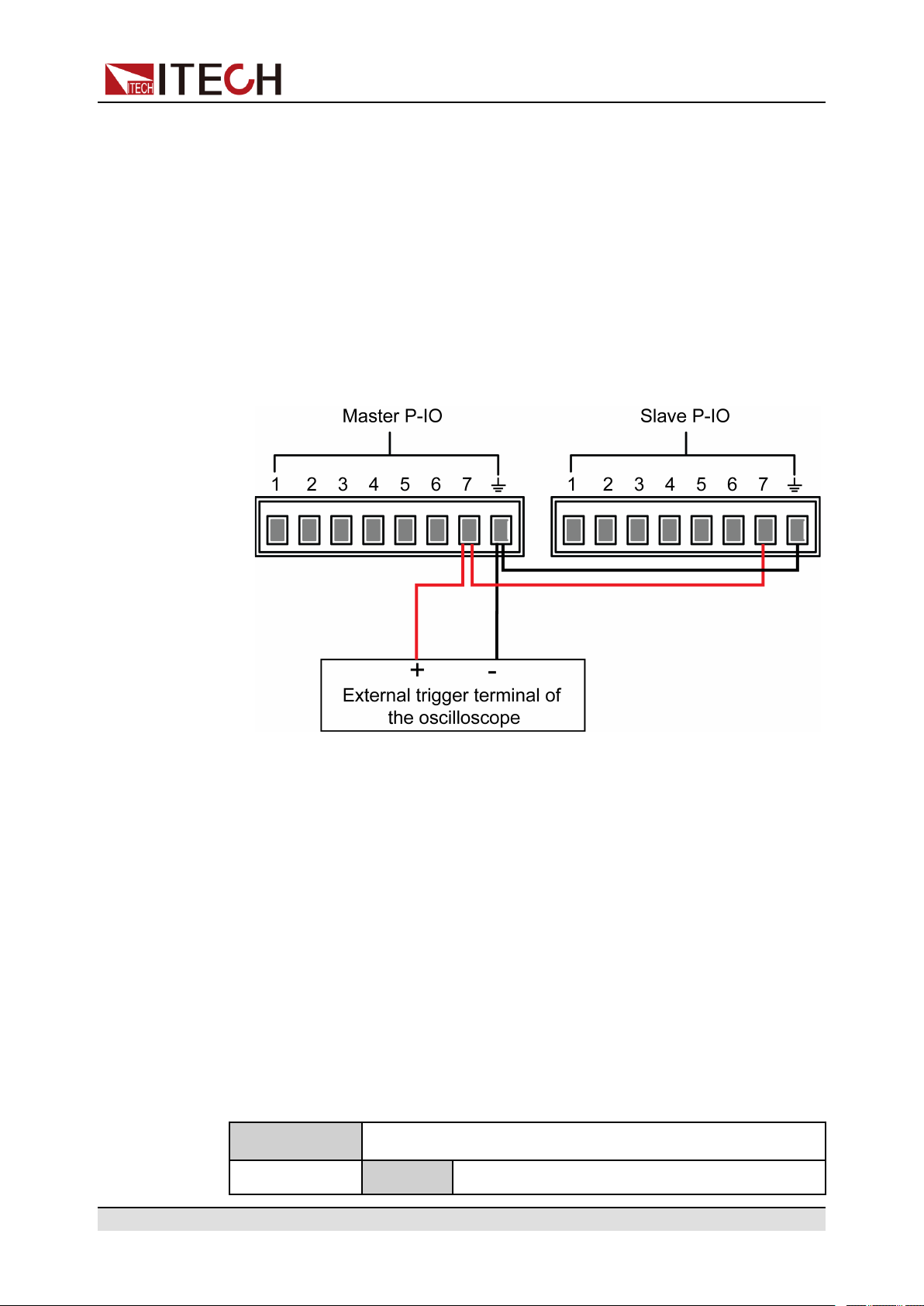
Basic Operation
ООО "Техэнком" Контрольно-измерительные приборы и оборудование www.tehencom.com
• Press [On/Off] on the instrument’s front panel, the instrument’s output is
changed from On to Off. At this point, the pulse signal output from pin 7 can
be detected.
• When the instrument’s [On/Off] is in Off state, input pulse signal to pin 7,
and it will not impact the [On/Off] state.
• When the instrument’s [On/Off] is in On state, input pulse signal to pin 7,
and [On/Off] will be changed from On to Off.
Taking two instruments in parallel as an example, the operation is as below:
1. Referring to the figure below, connect pin 7 of two instruments to the external
oscilloscope.
2. Set pin 7’s function of two instruments to Not-Invert and Sync-Off.
3. Confirm that the master and the salve’s [On/Off] are both in On State.
4. Press [On/Off] on the master’s front panel, and turn off the master’s output
function.
At this time, check the oscilloscope. The master’s pin 7 outputs pulse signal
and the slave’s output function is synchronously switched off.
3.6.8 (Optional) Analogue Function (Ext-Program)
This menu item is used to control whether the external analog function is turned
on. This function is not standard with the instrument and is optional for users. If
the user does not select this function, this menu item will not be displayed.
The detailed parameter description is as below.
Ext-Program External analog function menu
On / Off Function switch:
Copyright © Itech Electronic Co., Ltd.
56
Page 68
• On: Turns on the external analog function.
ООО "Техэнком" Контрольно-измерительные приборы и оборудование www.tehencom.com
In this state, the channel parameters cannot
be set.
• Off: Turns off the external analog function.
In this state, the channel parameters can be
set.
Ch1 Set the parameters of channel 1.
M1 Indicates the slope factor of channel 1.
Mb Indicates the offset of channel 1.
Ch2 Set the parameters of channel 2.
M2 Indicates the slope factor of channel 2.
Mb Indicates the offset of channel 2.
Ch3 Set the parameters of channel 3.
Basic Operation
M3 Indicates the slope factor of channel 3.
Mb Indicates the offset of channel 3.
3.6.9 Restored to Factory Setting (System Reset)
This menu item is used to restore some parameter settings to factory setting
values.
The procedures to set the menu item are as follows.
1. Press the composite keys [Shift]+[P-set] (System) on the front panel to enter the system menu.
2. Press the Up/Down key or turn the knob to select the System Reset and
press [Enter].
3. Press the Left / Right key or turn the knob to adjust the value of this
parameter.
• No: Default value, indicates the instrument cancels this menu setting.
• Yes: Indicates the instrument restores the factory default settings.
4. After the parameter settings are complete, press [Enter].
The parameters affected by System Reset and the parameter values after
reset are shown in Table 3–3 Initial value of the parameter.
Copyright © Itech Electronic Co., Ltd.
57
Page 69

Basic Operation
ООО "Техэнком" Контрольно-измерительные приборы и оборудование www.tehencom.com
Table 3–3 Initial value of the parameter
Category Parameter Initial Value
Main
interface
System
menu
Voltage setting: Vs One percent of the rated
voltage of the
instrument
Current setting: Is One percent of the rated
current of the instrument
Upper limit of voltage: Vh, and
lower limit of voltage: Vl
Upper limit of current: I+, and
lower limit of current: I-
Upper limit of power: P+, and
lower limit of power: P-
[On/Off] status Off
Beep On
PowerOn Reset
Upper limit value: One
percent of the rated voltage of the instrument
Lower limit value: 0
One percent of the rated
current of the instrument
Rated power value of
the instrument
Sense Off
ListTrig Source Manual
DataLogger Trig Source Manual
I/O Con
• LAN→IP-Conf
• IP Addr:
• SubNet:
• Gateway:
• DNS1/DNS2:
• Socket Port:
LAN→Serv-Conf
192.168.0.1
255.255.255.0
192.168.0.1
0.0.0.0
30000
Copyright © Itech Electronic Co., Ltd.
58
Page 70

Basic Operation
ООО "Техэнком" Контрольно-измерительные приборы и оборудование www.tehencom.com
Category Parameter Initial Value
MDNS/PING/Telnet-
scpi/Web/VX-11/
Raw-socket: On
• VCP: 9600,8,N,1
• (Optional) RS232:
9600,8,N,1
• (Optional) External
analog: Off
• (Optional) GPIB: Ad-
dress=1
Config
menu
Digital Port
• IO–1: Ps-Clear
• IO–2: Ps
• IO–3: Off-Status
• IO–4: Ext-Trig
• IO–5: INH-Living
• IO–6: Sync-On
• IO–7: Sync-Off
Parallel Single
Mode CV
Speed High
V-Rise Time/I-Rise Time 0.1s
V-Fall Time/I-Fall Time
Output Res 1000
On Delay/Off Delay 0
Protect
menu
Copyright © Itech Electronic Co., Ltd.
OVP/OCP/OPP/UCP/UVP Sta-
tus switch
OVP/OCP/OPP Protection point:
Level
UCP/UVP Protection point:
Level
Off
Rated voltage / current /
power value of the
instrument
0
59
Page 71

Basic Operation
ООО "Техэнком" Контрольно-измерительные приборы и оборудование www.tehencom.com
Category Parameter Initial Value
OVP/OCP/OPP/UCP/UVP Delay
time: Delay
UCP/UVP Warm time: Warm-up
60s
3.6.10 View the System Information (System Info)
This menu item is used to view the system information of the instrument.
The procedures to view the system information are as follows.
1. Press the composite keys [Shift]+[P-set] (System) on the front panel to enter the system menu.
2. Press the Up/Down key or turn the knob to select the System Info and press
[Enter].
You can use Up/Down key or knob to view the following system information.
Parameter Description
Model Display the instrument model.
MAC Addr Display the MAC address, that is, the physical
SN Display the serial number.
Main-Ver Display the system version information.
Ctrl-Ver Display the version information for a single
FPGA-Ver Display the FPGA version information.
INV-Ver Display the control board version information.
2017/6/22 0:00 Display the system time.
3.7 System Upgrade
address.
module.
The IT6000C series power supply supports the upgrade of the system version.
System upgrade includes the following two methods:
Copyright © Itech Electronic Co., Ltd.
60
Page 72

• During the start-up period after the instrument is powered on, through the
ООО "Техэнком" Контрольно-измерительные приборы и оборудование www.tehencom.com
USB interface on the front panel, select the system upgrading files in the
memory device (U key) for upgrading.
• The user can access to the Web service programs in the instrument by the
Web browser on PC for upgrading operation.
This Chapter introduces in detail how to upgrade the system with the USB interface on the front panel. For the upgrading method of Web, see 5.6 Web Server.
Before You Upgrade
Before upgrading, you need to note the following points:
1. Description about system upgrading files.
Before upgrading, please contact ITECH technical staff to obtain the follow-
ing two upgrading files, and put them under the root directory of the U key.
• itech_6000_P.itech
Basic Operation
2. The upgrading methods for single unit or units in parallel are slightly differ-
3. If the upgrade fails, the interface will prompt Update fail. At this point, you
Upgrade Operation
• System Upgrade under Single-unit Mode
System upgrading package postfixed with .itech.
• ItechConfig.txt
System upgrading package in text format.
ent: Under the parallel mode, the user can select to upgrade all units or a
single unit only by operating the master. Therefore, the user needs to get access to SN numbers of all instruments in the parallel network (To obtain the
unique ID for identifying instrument, see 3.6.10 View the System Information
(System Info)) for selective upgrading based on the SN number in subse-
quent upgrades.
cannot use the instrument. Please contact ITECH technical staff for
treatment.
1. Insert the U key into the USB interface on the front panel of the
instrument.
2. Power on the instrument. At this point, press Shift for several times till
the instrument can detect the system upgrading files in the U key.
After the system upgrading files are detected, the interface displays as
follows:
Copyright © Itech Electronic Co., Ltd.
61
Page 73

Update Select(01/01)
ООО "Техэнком" Контрольно-измерительные приборы и оборудование www.tehencom.com
SN: ALL
If the U key is not detected, select Yes to detect again; if No is se-
lected, it means to exit upgrading, and the system will directly enter in-
to the main interface.
3. Select ALL, and press [Enter].
The system interface displays as follows:
Update ? (01/01)
No Yes
4. Select Yes, and press [Enter].
The system will automatically perform upgrading.
Basic Operation
If No is selected, it means to exit upgrading, and the system will di-
rectly enter into the main interface.
5. After the upgrading is completed, you need to restart the instrument
manually.
• System Upgrade under Parallel Mode (Only Need to Operate the Master)
1. Insert the U key into the USB interface on the front panel of the
instrument.
2. Power on the instrument. At this point, press Shift for several times till
the instrument can detect the system upgrading files in the U key.
After the system upgrading files are detected, the interface displays as
follows:
Update Select(xx/yy)
SN: ALL
xx means the number of selected instruments to be upgraded, and yy
means the number of instruments in the parallel network.
3. Select upgrade in whole or in part based on actual needs. Then, press
[Enter].
– SN: ALL
Indicates to upgrade all.
– SN1: xxxxxxxxxxxxxxxxxx
Copyright © Itech Electronic Co., Ltd.
62
Page 74

Basic Operation
ООО "Техэнком" Контрольно-измерительные приборы и оборудование www.tehencom.com
Indicates to upgrade the selected instrument. Press Up/Down to
check the SNs of all instruments in the parallel network; press Right
to select the instrument; and press Right again to deselect the
instrument.
4. Select Yes, and press [Enter].
The system will automatically perform upgrading.
If No is selected, it means to exit upgrading, and the system will di-
rectly enter into the main interface.
5. After the upgrading is completed, you need to restart the instrument
manually.
Copyright © Itech Electronic Co., Ltd.
63
Page 75

4 Power Supply Function
ООО "Техэнком" Контрольно-измерительные приборы и оборудование www.tehencom.com
This chapter describes the functions and features of the power supply. Divided
into the following sections:
♦ Set the Output Voltage
♦ Set the Output Current
♦ Set the Output Power
♦ Configuration Menu Function for Power Supply
♦ Protection Function for Power Supply
♦ Function Menu for Power Supply
4.1 Set the Output Voltage
Power Supply Function
In CV priority (default) mode, press [V-set], the interface displays “Vs=0.00V”
(Setting value of voltage). In CC priority mode, press [V-set], the interface displays “Vh=0.00V” (Upper limit of voltage), and press [V-set] again, the interface
displays “Vl=0.00V” (Lower limit of voltage).
The voltage setting range is from 0V to the maximum rated output voltage.
When [V-set] key is pressed, the key light is lit and the output voltage value can
be set. Press numeric keys or rotate the knob to adjust the value in the voltage
setting area indicated by the cursor. This value takes effect when you press
[Enter].
4.2 Set the Output Current
In CV priority (default) mode, press [I-set], the interface displays “I+=0.00A”
(Upper limit of current) , and press [I-set] again, the interface displays “I-= –
0.00 A” (Lower limit of current). In CC priority mode, press [I-set], the interface
displays “Is=0.00A” (Setting value of current).
The range of current settings is between the data ranges defined in the specifications. When [I-set] key is pressed, the key light is lit and the output current
value can be set. Press numeric keys or rotate the knob to adjust the value in
the current setting area indicated by the cursor. This value takes effect when
you press [Enter].
Copyright © Itech Electronic Co., Ltd.
64
Page 76

For the bi-directional power supply, you can set the direction of the current
ООО "Техэнком" Контрольно-измерительные приборы и оборудование www.tehencom.com
(output / input), that is, control the positive or negative current value by press-
ing the [+/-] key.
4.3 Set the Output Power
Press [P-set], the interface displays “P+=0.00W” (Upper limit of power) , and
press [P-set] again, the interface displays “P- = – 0.00W” (Lower limit of power)
.
The range of power settings is between the data ranges defined in the specifications. When [P-set] key is pressed, the key light is lit and the output power value
can be set. Press numeric keys or rotate the knob to adjust the value in the
power setting area indicated by the cursor. This value takes effect when you
press [Enter].
Power Supply Function
For the bi-directional power supply, you can set the direction of the power
(output / input), that is, control the positive or negative power value by press-
ing the [+/-] key.
4.4 Configuration Menu Function for Power Supply
This section gives an overview of the configuration menu of the IT6000C series
power supply.
The procedures to operate the configuration menu are as follows.
1. Press the composite keys [Shift]+[V-set] (Config) on the front panel to enter
the configuration menu.
The VFD shows configuration menu items and each menu item is marked
with a number. The user can use up and down keys or knob to scroll pages
to view the other menu items.
2. Press [Enter] to select the desired menu item.
Enter the parameter setting interface of this menu item.
3. After finishing the menu setting, press [Enter] key to save the setting.
Copyright © Itech Electronic Co., Ltd.
65
Page 77

Power Supply Function
ООО "Техэнком" Контрольно-измерительные приборы и оборудование www.tehencom.com
Press [Esc] key to return to the previous menu level.
The descriptions of configuration menu are listed in the table below.
Config Configuration menu of the power supply
Mode
CC/CV priority mode setting
CV
CC
V-Rise Time/I-Rise Time
= 0.001s
Constant voltage loop priority mode
Loop response
Speed= High/Low
speed setting:
high speed /
low speed
Constant current loop priority mode
Loop response
Speed= High/Low
speed setting:
high speed /
low speed
Displays the voltage or current rise time
setting according to the selected priority
mode. If CC priority mode is selected,
the parameter setting of I-Rise Time will
be displayed here.
Displays the voltage or current fall time
setting according to the selected priority
V-Fall Time/I-Fall Time =
0.001s
mode. If CC priority mode is selected,
the parameter setting of I-Fall Time will
be displayed here.
Set the internal resistance of the power
Output Res
supply. This parameter needs to be set
only when Mode is set to CV.
On Delay Set the delay time to turn on the output.
Off Delay Set the delay time to turn off the output.
Copyright © Itech Electronic Co., Ltd.
66
Page 78
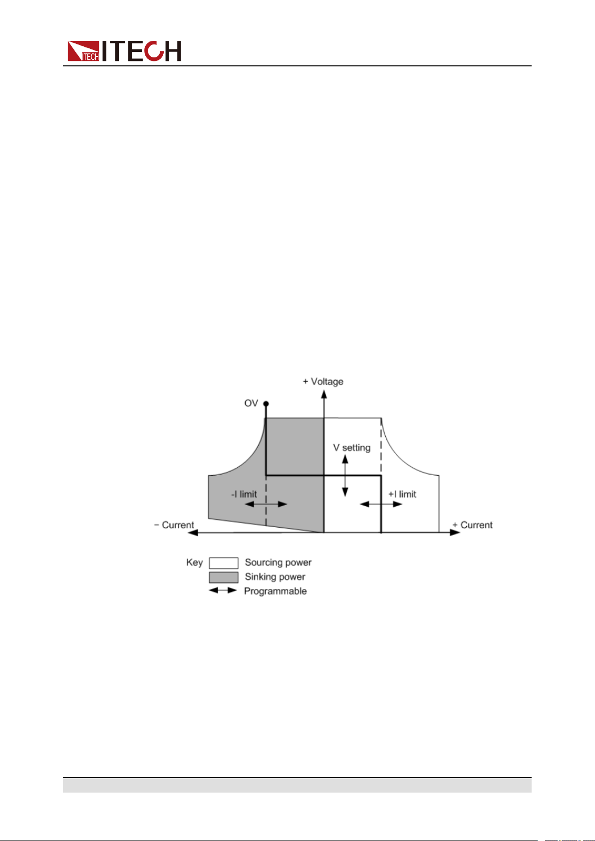
4.4.1 Set the CC/CV Priority Mode
ООО "Техэнком" Контрольно-измерительные приборы и оборудование www.tehencom.com
CV Priority
In CV priority mode, the output is controlled by a constant-voltage feedback
loop, which maintains the output voltage at its programmed setting as long as
the load current remains within the positive or negative current limit settings. CV
priority mode is best suited for use with resistive or high impedance loads, and
loads that are sensitive to voltage overshoots. Do not use CV priority mode with
low-impedance sources such as batteries, power supplies, or large charged
capacitors.
In CV priority mode, the output voltage should be programmed to the desired
value. A positive and negative current limit value should also be set. The current
limit should always be set to a value that is greater than the actual input current
requirement of the external load. The following figure shows the CV priority operating locus of the output. The area in the white quadrants shows the output as
a source (sourcing power). The area in the shaded quadrants shows the output
as a load (sinking power).
Power Supply Function
The heavy solid line illustrates the locus of possible operating points as a func-
tion of output. As shown by the horizontal portion of the line, the output voltage
remains regulated at its programmed setting as long as the load current remains
within the positive or negative current limit setting. A CV status flag indicates
that the output voltage is being regulated and the output current is within its limit
settings.
Note that when the output current reaches either the positive or negative current
limit, the unit no longer operates in constant voltage mode and the output
Copyright © Itech Electronic Co., Ltd.
67
Page 79

CC Priority
ООО "Техэнком" Контрольно-измерительные приборы и оборудование www.tehencom.com
Power Supply Function
voltage is no longer held constant. Instead, the unit will now regulate the output
current at its current limit setting.
As shown by the vertical portions of the shaded quadrants, the output voltage
may continue to increase in the positive direction or decrease in the negative di-
rection as current is forced into or pulled out of the unit. When the output voltage
exceeds the over-voltage protection setting, the output will shut down.
In CC priority mode, the output is controlled by a bi-polar constant current feedback loop, which maintains the output source or sink current at its programmed
setting. The output current remains at its programmed setting, provided the load
voltage remains within the voltage limit setting. CC priority mode is best suited
for use with batteries, power supplies, large charged capacitors, and loads that
are sensitive to current overshoots. It minimizes current overshoots during programming, turn-on, and turn-off transitions and seamlessly transitions between
positive and negative currents.
In CC priority mode, the output current should be programmed to the desired
positive or negative value. A positive voltage limit range should also be set. The
voltage upper limit should always be set to a value that is greater than the actual
input voltage requirement of the external load. The following figure shows the
CC priority operating locus of the output. The area in the white quadrants shows
the output as a source (sourcing power). The area in the shaded quadrants
shows the output as a load (sinking power).
The heavy solid line illustrates the locus of possible operating points as a function of output. As shown by the vertical portion of the line, the output current re-
mains regulated at its programmed setting as long as the output voltage
Copyright © Itech Electronic Co., Ltd.
68
Page 80

Power Supply Function
ООО "Техэнком" Контрольно-измерительные приборы и оборудование www.tehencom.com
remains within its limit setting. A CC (constant current) status flag indicates that
the output current is being regulated and the output voltage is within its limit
settings.
Note that when the output voltage reaches the upper limit, the unit no longer op-
erates in constant current mode and the output current is no longer held constant. Instead, the unit will now regulate the output voltage at its voltage limit
setting.
As shown by the horizontal portion of the shaded quadrants, when the unit is
sinking power, the output current may continue to increase in the negative direction as more current is forced into the unit. This can happen when the instru-
ment is connected to an external device such as a battery, and its output
voltage is higher than the voltage limit setting of the instrument. Once the current exceeds the built-in negative over-current limit, the output will shut down. In
such a case, it is important to set the voltage limit properly in order prevent this
protection shutdown.
How to Set
The procedures to set the output priority mode are as follows.
1. Press the composite keys [Shift]+[V-set] (Config) on the front panel to enter
the configuration menu.
2. Select Mode and press [Enter] to enter into the setting interface.
3. Select CC or CV, and press [Enter].
Enter the setting interface of the loop response speed.
4. Select High or Low, and press [Enter].
At this point, return to the Config menu settings interface.
5. Press the down arrow key to set the voltage/current rise time. When finished,
press [Enter].
6. Set the other Config menu items in the same way.
7. Set the output voltage and current value.
• CV priority
a. Press the [V-set] key on the front panel to set the output voltage val-
ue Vs.
b. Press the [I-set] key on the front panel to set the current upper limit I
+. Press [I-set] again to set the current lower limit I-, i.e. the negative
current limit value.
• CC priority
a. Press the [I-set] key on the front panel to set the output current value
Is.
b. Press the [V-set] key on the front panel to set the voltage upper limit
Vh, and press [V-set] again to set the voltage lower limit Vl.
Copyright © Itech Electronic Co., Ltd.
69
Page 81

4.4.2 Set the Internal Resistance
ООО "Техэнком" Контрольно-измерительные приборы и оборудование www.tehencom.com
The IT6000C series power supply provides internal resistance setting (CV priority mode only). The procedures are shown as below.
1. Press the composite keys [Shift]+[V-set] (Config) on the front panel to enter
the configuration menu.
2. Press the up/down key or rotate the knob to select Output Res and press
[Enter] to confirm.
3. Set the internal resistance value and press [Enter] to confirm.
4.4.3 Set the Output-On/Output-Off Delay
You can set the output-on/output-off delay time within the range from 0 seconds
to 60 seconds.
• On Delay: Indicates from the time that a command to turn on the output is re-
ceived until the output actually turns on.
Power Supply Function
• Off Delay: Indicates from the time that a command to turn off the output is re-
ceived until the output actually turns off.
The procedures to set the output delay time are as follows.
1. Press the composite keys [Shift]+[V-set] (Config) on the front panel to enter
the configuration menu.
2. Press the up/down key or rotate the knob to select On Delay or Off Delay,
and press [Enter] to confirm.
3. Set the output-on/output-off delay time and press [Enter] to confirm.
4.5 Protection Function for Power Supply
The IT6000C series power supply provides the general protection functions
such as overvoltage, overcurrent, overpower, undercurrent and undervoltage
protection. The corresponding protection parameters can be configured in the
Protect menu. In addition, the power supply also provides over temperature protection and Sense reverse connection protection.
The descriptions of Protect menu are listed in the table below.
Protect
Protection function menu for the power supply
OVP
Copyright © Itech Electronic Co., Ltd.
Overvoltage protection
Off
On Turn the OVP function on.
Turn the OVP function off. (Def)
70
Page 82

Power Supply Function
ООО "Техэнком" Контрольно-измерительные приборы и оборудование www.tehencom.com
Level OVP limit
OCP
OPP
Delay
Overcurrent protection
Off
On Turn the OCP function on.
Overpower protection
Off
On Turn the OPP function on.
Turn the OCP function off. (Def)
Level OCP limit
Delay
Turn the OPP function off. (Def)
Level OPP limit
Delay
Protection delay time,
see Protection Delay.
Protection delay time,
see Protection Delay.
Protection delay time,
see Protection Delay.
UCP
Undercurrent protection
Off
On Turn the UCP function on.
Turn the UCP function off. (Def)
Indicates the instrument
warm-up time. This time
is set to prevent the instrument from triggering
protection when the cur-
Warm-up
Level UCP limit
rent is rising. Because
this transient condition
should not be considered as an undercurrent
fault and there is no
need to trigger
protection.
Delay
UVP
Copyright © Itech Electronic Co., Ltd.
Undervoltage protection
Protection delay time,
see Protection Delay.
71
Page 83

Power Supply Function
ООО "Техэнком" Контрольно-измерительные приборы и оборудование www.tehencom.com
Off
On Turn the UVP function on.
Turn the UVP function off. (Def)
Indicates the instrument
warm-up time. This time
is set to prevent the in-
strument from triggering
protection when the
Warm-up
Level UVP limit
Delay
voltage is rising. Because this transient
condition should not be
considered as an
undervoltage fault and
there is no need to trigger protection.
Protection delay time,
see Protection Delay.
Protection Delay
You can specify an OCP/OVP/OPP/UCP/UVP delay to prevent momentary output settings and status changes from tripping the protection. In most cases
these momentary conditions would not be considered an protection fault, and
having an OCP/OVP/OPP/UCP/UVP condition disable the output when they occur would be a nuisance. Specifying an protection delay (Delay) can ignore
these momentary changes during the specified delay period. Once the delay
time has expired and the protection limit condition persists, the output will shut
down.
Fault Prompt
When the instrument enters the protection state, the buzzer sounds (if Beep
menu item is set as default state On), the VFD status indicators Prot and Off
are lit, and [On/Off] is turned off.
Although [On/Off] is turned off, there may be dangerous voltage at
the output electrodes. Do not touch the wiring cable or the electrode
terminals.
Copyright © Itech Electronic Co., Ltd.
72
Page 84

When protection is generated, the VFD screen displays the following
ООО "Техэнком" Контрольно-измерительные приборы и оборудование www.tehencom.com
information:
• The first row shows the meter voltage and the meter current value.
• The second row shows specific fault information, such as OVP.
Clear the Protection
After the instrument triggers protection and generates a fault message, you
need to troubleshoot the possible cause. When the fault is resolved, the VFD
will still prompt the fault information. You can manually clear the fault information
record through the following methods.
• Input a pulse signal to pin 1 of the rear panel P-IO to clear the fault
information.
For details, see 3.6.7.1 IO–1. Ps-Clear, Not-Invert.
• Press the [Esc] or [Enter] key on the front panel to manually clear the fault
information.
Power Supply Function
• Connected to the host computer, the PC sends a PROTection:CLEar com-
mand to the instrument to clear the fault information.
After the protection fault is cleared, you need to press the [On/Off] key on the
front panel or send the OUTPut ON command to the instrument to reopen
[On/Off].
4.5.1 Set Over-Voltage Protection (OVP)
Users can enable the OVP function and set the protection limit Level and protection delay time Delay. When the voltage (i.e., the Meter value) is greater than
this protection limit and the delay time is exceeded, the power supply will enter
the OVP state.
Possible Cause
Many reasons can cause OVP, the details are as follows:
• The set protection limit Level is lower than the voltage Meter value.
• Input too high external voltage.
• The power supply outputs a high voltage due to a fault.
Copyright © Itech Electronic Co., Ltd.
73
Page 85

How to Set
ООО "Техэнком" Контрольно-измерительные приборы и оборудование www.tehencom.com
Power Supply Function
Please avoid inputting a external voltage higher than 120% rated value, or the instrument will be damaged.
The operation steps to set OVP are as follows.
1. Press the composite keys [Shift]+[Recall] (Protect) on the front panel to enter the protection menu.
2. Press the up/down key or rotate the knob to select 1. OVP (Off) and press
[Enter].
3. Press the left/right key or rotate the knob to select On and press [Enter] to
enter the setting interface.
4. Set the protection limit Level and the delay time Delay in sequence, and
press [Enter] to confirm.
The VFD screen returns to the Protect menu and the OVP setting (take
150V, 1S as an example) is displayed as follows:
PROTECT
1.OVP 150V, 1S
4.5.2 Set Over-Current Protection (OCP)
Users can enable the OCP function and set the protection limit Level and protection delay time Delay. When the current (i.e., the Meter value) is greater than
this protection limit and the delay time is exceeded, the power supply will enter
the OCP state.
Possible Cause
Many reasons can cause OCP, the details are as follows:
• The set protection limit Level is lower than the current Meter value.
• Input too high external current.
• The power supply outputs a high current due to a fault.
How to Set
The operation steps to set OCP are as follows.
Copyright © Itech Electronic Co., Ltd.
74
Page 86

Power Supply Function
ООО "Техэнком" Контрольно-измерительные приборы и оборудование www.tehencom.com
1. Press the composite keys [Shift]+[Recall] (Protect) on the front panel to enter the protection menu.
2. Press the up/down key or rotate the knob to select 2. OCP (Off) and press
[Enter].
3. Press the left/right key or rotate the knob to select On and press [Enter] to
enter the setting interface.
4. Set the protection limit Level and the delay time Delay in sequence, and
press [Enter] to confirm.
For bi-directional power supplies, Level can be set to a positive or nega-
tive value, i.e. the same protection limit is set for the output or input
current.
The VFD screen returns to the Protect menu and the OCP setting (take 10A,
1S as an example) is displayed as follows:
PROTECT
2.OCP 10A, 1.000S
4.5.3 Set Over-Power Protection (OPP)
Users can enable the OPP function and set the protection limit Level and protection delay time Delay. When the power (i.e., the Meter value) is greater than
this protection limit and the delay time is exceeded, the power supply will enter
the OPP state.
Possible Cause
Many reasons can cause OPP, the details are as follows:
• The set protection limit Level is lower than the power Meter value.
• Input too high external power.
• The power supply outputs a high power due to a fault.
How to Set
The operation steps to set OPP are as follows.
1. Press the composite keys [Shift]+[Recall] (Protect) on the front panel to enter the protection menu.
2. Press the up/down key or rotate the knob to select 3. OPP (Off) and press
[Enter].
Copyright © Itech Electronic Co., Ltd.
75
Page 87

3. Press the left/right key or rotate the knob to select On and press [Enter] to
ООО "Техэнком" Контрольно-измерительные приборы и оборудование www.tehencom.com
enter the setting interface.
4. Set the protection limit Level and the delay time Delay in sequence, and
press [Enter] to confirm.
For bi-directional power supplies, Level can be set to a positive or nega-
tive value, i.e. the same protection limit is set for the output or input
power.
The VFD screen returns to the Protect menu and the OPP setting (take
150W, 1S as an example) is displayed as follows:
PROTECT
3.OPP 150W, 1.000S
4.5.4 Set Under-Current Protection (UCP)
Power Supply Function
Possible Cause
How to Set
Users can enable the UCP function and set the instrument warm-up time
Warm-up, protection limit Level and protection delay time Delay. When the current (i.e., the Meter value) is lower than this protection limit and the warm-up
time, delay time are exceeded, the power supply will enter the UCP state.
Many reasons can cause UCP, the details are as follows:
• The set protection limit Level is greater than the current Meter value.
• Input too low external current.
• The power supply outputs a low current due to a fault.
The operation steps to set UCP are as follows.
1. Press the composite keys [Shift]+[Recall] (Protect) on the front panel to en-
ter the protection menu.
2. Press the up/down key or rotate the knob to select 4. UCP (Off) and press
[Enter].
3. Press the left/right key or rotate the knob to select On and press [Enter] to
enter the setting interface.
4. Set the warm-up time Warm-up, protection limit Level and delay time Delay
in sequence, and then press [Enter] to confirm.
Copyright © Itech Electronic Co., Ltd.
76
Page 88

For bi-directional power supplies, Level can be set to a positive or nega-
ООО "Техэнком" Контрольно-измерительные приборы и оборудование www.tehencom.com
tive value, i.e. the same protection limit is set for the output or input
current.
The VFD screen returns to the Protect menu and the UCP setting (take 10S,
0.1A, 1S as an example) is displayed as follows:
PROTECT
4.UCP 10S, 0.1A, 1.000S
4.5.5 Set Under-Voltage Protection (UVP)
Users can enable the UVP function and set the instrument warm-up time
Warm-up, protection limit Level and protection delay time Delay. When the
voltage (i.e., the Meter value) is lower than this protection limit and the warm-up
time, delay time are exceeded, the power supply will enter the UVP state.
Power Supply Function
Possible Cause
How to Set
Many reasons can cause UVP, the details are as follows:
• The set protection limit Level is greater than the voltage Meter value.
• Input too low external voltage.
• The power supply outputs a low voltage due to a fault.
The operation steps to set UVP are as follows.
1. Press the composite keys [Shift]+[Recall] (Protect) on the front panel to enter the protection menu.
2. Press the up/down key or rotate the knob to select 5. UVP (Off) and press
[Enter].
3. Press the left/right key or rotate the knob to select On and press [Enter] to
enter the setting interface.
4. Set the warm-up time Warm-up, protection limit Level and delay time Delay
in sequence, and then press [Enter] to confirm.
The VFD screen returns to the Protect menu and the UVP setting (take 10S,
1V, 1S as an example) is displayed as follows:
PROTECT
5.UVP 10S, 1V, 1.000S
Copyright © Itech Electronic Co., Ltd.
77
Page 89

4.5.6 Over-Temperature Protection (OTP)
ООО "Техэнком" Контрольно-измерительные приборы и оборудование www.tehencom.com
When internal temperature of instrument is higher than about 90 °C, the instrument is under temperature protection. At this time, the instrument will automati-
cally be OFF and VFD status indicator Prot lights up and the screen prompts
OTP.
Possible Cause
To prevent damaging heat build-up and ensure specified performance, make
sure there is adequate ventilation and air flow around the instrument to ensure
proper cooling. Do not cover the ventilation holes on the rear panel, sides, or
bottom of the instrument. Even with proper ventilation, the instrument can overheat in the following situations.
• If the ambient temperature is too high.
• If you use the instrument to test for long periods.
Power Supply Function
How to Set
The OTP limit does not need to be set, and the internal device of the instrument
automatically detects and determines whether to enter the OTP state.
If an over-temperature condition occurs, power off the instrument and allow it to
cool for at least 30 minutes. After the internal temperature of the instrument has
cooled down, power it on again.
When you return power to the instrument, verify that the cooling fan is
running. If not, please contact ITECH Technical Support. Leaving the
instrument powered on with an inoperative cooling fan may result in
damage to the instrument.
4.5.7 Sense Reverse Protection
The instrument defaults to provide sense reverse protection. When the output
state is ON and the difference between output terminal voltage and sense remote voltage exceeds the specified voltage, sense reverse protection will be enabled after 500ms. The instrument output will be immediately switched to Off
and the display screen will display Sense Reverse Prot if the sense terminals
are reversed.
Copyright © Itech Electronic Co., Ltd.
78
Page 90

When the instrument is in Sense Reverse Protection state, you should check
ООО "Техэнком" Контрольно-измерительные приборы и оборудование www.tehencom.com
whether the polarities are connected reversely or not firstly. If yes, you can reopen the output after the polarities connect correctly.
The voltage difference between output terminal and remote sense terminal of
each model is not the same. When the remote sense terminal is connected reversely, the maximum voltage will not exceed the sum of output terminal voltage
and the difference voltage.
4.6 Function Menu for Power Supply
The Function menu of the power supply includes the following:
Function Function Menu for Power Supply
LIST LIST program editing, file import/export, pro-
gram running (see 4.6.1 LIST Function).
Power Supply Function
4.6.1 LIST Function
The IT6000C series power supply supports a total of 10 List files (List01 to
List10), each of which can be set up to 200 steps. You need to edit the voltage/
current value, slope and time width of each step, or you can set repeat times (1
to 65535) for each List file. After the file is edited completely, you can trigger the
selected List file to run according to the selected trigger mode.
BATTERY Battery charging and discharging testing
function (see 4.6.2 Battery Charging/Dis-
charging Test Function).
Road-Vehicles Built-in waveform function (see 4.6.3 Built-in
Waveform Function).
SAS PV simulation function (see 4.6.4 Solar Pho-
tovoltaic Curve Simulation Function (SAS)).
The descriptions of list function menu are listed in the table below.
LIST List menu
Run Indicates to enter the List run mode, waiting for the trigger to
run the currently selected List file.
Open Select the List file to open.
Copyright © Itech Electronic Co., Ltd.
79
Page 91

Power Supply Function
ООО "Техэнком" Контрольно-измерительные приборы и оборудование www.tehencom.com
USB Open the List file in the external USB flash disk.
Load Import the List file from the exter-
nal USB flash disk into the
instrument.
Not-Load Cancel the import operation.
Internal Open the List file stored inside the instrument.
Recall Inner
File
Export Export the internal List file of the instrument to an external
USB flash drive.
File
Name
Edit Edit list program.
CC / CV Set the operation mode for list program: CC prior-
Step
Count
Step 1
Value
The name of the exported list file. The default suffix is .csv, and the file name can only be a string
of numbers.
ity or CV priority.
The total number of steps included in the List
program.
Current value or voltage value setting for Step1.
(The voltage appears when CV priority is selected; the current appears when CC priority is
selected.)
Set the name of the recalled List
file.
Step 1
Slope
Step 1
Width
Repeat Set the number of list file repetitions.
End
State
Copyright © Itech Electronic Co., Ltd.
Slope value setting for Step1.
Dwell time setting for Step1.
Set the running state after the list program is running over.
Last After the List program finishes run-
ning, the output is kept as the setting in the last step, and the
working mode remains as the setting in the List file.
80
Page 92
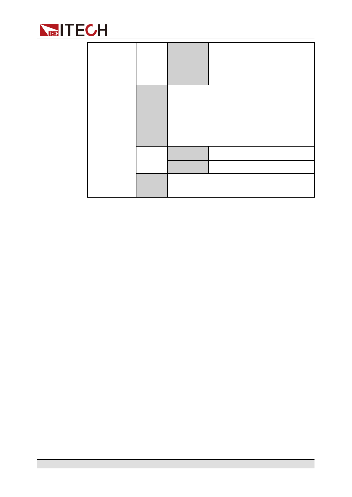
Power Supply Function
ООО "Техэнком" Контрольно-измерительные приборы и оборудование www.tehencom.com
Normal After the List program finishes run-
ning, the working mode and voltage/current output return to the
settings before the List running.
Trig Out Function switch that triggers the signal output. It
is applicable to the scenario of synchronously
controlling multiple units, that is, by connecting
the outer loop interfaces TX and RX of the fiber to
realize List synchronization triggering between
multiple units.
None Turn off (default)
Tout Turn on
Edit List Program
The following takes CC priority mode as an example to introduce the operation
of editing two test steps.
1. Press the composite keys [Shift]+[I-set] (Function) on the front panel to en-
2. Select 1. LIST: Off and press [Enter].
3. Press the Left/Right key to select Edit and press [Enter] to enter the editing
4. Select CC and press [Enter] to confirm.
5. Set the total number of steps in the List program and press [Enter] to
Save to
group
ter the function menu.
interface.
confirm.
Save the edited List program.
6. Set the current, slope and time width of step 1 in turn, and press [Enter] to
confirm.
7. Set the parameters of step 2 in the same method.
8. Set the number of list repetitions Repeat, and press [Enter] to confirm.
9. Set the End State as Normal, and press [Enter] to confirm.
10.Depending on the test requirement, choose whether to turn on the function
switch that triggers synchronization.
11. Set the currently edited List program name.
Copyright © Itech Electronic Co., Ltd.
81
Page 93

If you choose not to save, press [Esc] to exit the editing interface.
ООО "Техэнком" Контрольно-измерительные приборы и оборудование www.tehencom.com
Import List Program
If you need to run the List program on the external USB flash drive, you need to
import the List program from the USB flash drive into the instrument.
The procedures are as follows:
1. Insert the USB flash drive into the front panel USB connector.
2. Press the composite keys [Shift]+[I-set] (Function) on the front panel to enter the function menu.
Power Supply Function
The format of the List file in the USB flash drive must be in .csv format and
saved in the root directory of the USB flash drive. You can refer to Export List
Program to customize editing according to the List file template exported to
the USB flash drive.
3. Select 1. LIST: Off and press [Enter].
4. Press the Left/Right key to select Open and press [Enter].
5. Select USB and press [Enter].
At this point, the system will automatically read all the List files in the root directory of the USB flash drive. The interface is displayed as follows:
XXX.csv
Not-Load Load YY/ZZ
XXX indicates the name of the List file; YY indicates the serial number of the
current List file; ZZ indicates the total number of the List file.
6. Press the Up/Down key to select the List file.
7. Press the Left/Right key to select Load, press [Enter] to complete the import, and wait for the trigger to run this List file.
At this point, the interface returns to the main interface of the system and
LIST RUN is displayed in the lower right corner.
Select Internal List Program
You can select a List file saved inside the instrument to be in the Open state
and wait for subsequent triggers to run. The procedures are as follows:
1. Press the composite keys [Shift]+[I-set] (Function) on the front panel to enter the function menu.
2. Select 1. LIST: Off and press [Enter].
Copyright © Itech Electronic Co., Ltd.
82
Page 94

3. Press the Left/Right key to select Open and press [Enter].
ООО "Техэнком" Контрольно-измерительные приборы и оборудование www.tehencom.com
4. Press the Left/Right key to select Internal and press [Enter].
5. Set the name of the List file to be recalled (that is, the file name set in Edit),
and press [Enter].
The interface returns to the main interface of the LIST function, which is dis-
played as follows:
FUNCTION LIST
Run Edit Open Export
If you select Run and press [Enter], the instrument will enter LIST mode
and wait for the trigger to run.
Export List Program
Supports exporting the internal List file to an external USB flash drive. The exported List file is saved in .csv format.
Power Supply Function
1. Insert the USB flash drive into the front panel USB connector.
2. Press the composite keys [Shift]+[I-set] (Function) on the front panel to enter the function menu.
3. Select 1. LIST: Off and press [Enter].
4. Press the Left/Right key to select Open and press [Enter].
5. Press the Left/Right key to select Internal and press [Enter].
6. Set the name of the List file to be recalled (that is, the file name set in Edit),
and press [Enter].
The interface returns to the main interface of the LIST function, which is displayed as follows:
FUNCTION LIST
Run Edit Open Export
7. Press the Left/Right key to select Export and press [Enter].
8. Press the Left/Right key to select Yes and press [Enter].
Indicates that the selected List file in Open is exported to the USB flash
drive.
Run the List Program
You can select a List file to execute according to your needs, so that the power
supply outputs the corresponding waveform sequence. Take the List file in
Internal as an example. The steps are as follows:
Copyright © Itech Electronic Co., Ltd.
83
Page 95

Power Supply Function
ООО "Техэнком" Контрольно-измерительные приборы и оборудование www.tehencom.com
1. Press the composite keys [Shift]+[I-set] (Function) on the front panel to enter the function menu.
2. Select 1. LIST: Off and press [Enter].
3. Press the Left/Right key to select Open and press [Enter].
4. Press the Left/Right key to select Internal and press [Enter].
5. Set the name of the List file to be recalled (that is, the file name set in Edit),
and press [Enter].
The interface returns to the main interface of the LIST function, which is displayed as follows:
FUNCTION LIST
Run Edit Open Export
6. Press the Left/Right key to select Run and press [Enter].
At this point, the interface returns to the main interface of the system and
LIST RUN is displayed in the lower right corner.
7. Turn on the [On/Off].
8. Based on the selected trigger method, perform the trigger operation.
Take the manual trigger as an example. Press [Shift]+[On/Off](Trigger) on
the front panel to run the selected List file. For details about the List trigger
method, see 3.6.4 Select Trigger Source (Trig Source).
• The system will adjust the working mode of the power supply according to
the CC or CV priority mode set in the List file. For example, if the current
power supply is in the CV priority mode, and the list file to be run is set to the
CC priority mode, then the power supply will work in the CC priority mode
after the List file is triggered to run.
• After the List file finishes running, the system determines whether to return
to the working mode before the List is run according to the Normal or Last
option you selected.
Stop Running the List Program
When the List program is running, if you need to stop running, you can do the
following: Press the composite keys [Shift]+[I-set] (Function) on the front panel
to enter the function menu.
At this point, the interface will prompt whether to stop the running of the Func-
tion (FUNCTION STOP?), you can press the Left/Right key to select Yes, then
the current running will be stopped, and the Function menu item will be displayed, you can re-enter the Function menu for editing; if No is selected, it
means that the current running will not be stopped, and the main interface of the
system is displayed.
Copyright © Itech Electronic Co., Ltd.
84
Page 96

Power Supply Function
ООО "Техэнком" Контрольно-измерительные приборы и оборудование www.tehencom.com
4.6.2 Battery Charging/Discharging Test Function
The IT6000C series power supply provides the battery charging/discharging test
function based on its unique bipolar power supply properties. Suitable for charg-
ing/discharging tests on all types of portable batteries.
BATTERY
Battery charging/discharging test function
Indicates that the battery test mode is entered and
Run
Edit
waits to trigger the running of the currently edited bat-
tery test file.
Edit the battery charging/discharging test file.
Set the test mode:
• Charge: Battery charging
Charge /
Discharge
• Discharge: Battery
discharging
According to the test requirements, choose one to set.
Charge /
Discharge
V
Set the voltage
value for charging
or discharging according to the se-
lected test mode.
Set the current val-
Charge /
Discharg I
Charge /
Discharg
Time
Cut Off Voltage Battery test cut-off voltage
Cut Off Current
Cut Off Capacity Battery test cut-off capacity
1. Press the composite keys [Shift]+[I-set] (Function) on the front panel to enter the function menu.
Battery test cut-off current
ue for charging or
discharging according to the selected test mode.
Set the charging
or discharging
time according to
the selected test
mode.
Copyright © Itech Electronic Co., Ltd.
85
Page 97

Power Supply Function
ООО "Техэнком" Контрольно-измерительные приборы и оборудование www.tehencom.com
2. Use knob or Up/Down key to select 2.BATTERY: Off and press [Enter].
The interface is displayed as follows:
FUNCTION BATTERY
Run Edit
3. Press the Left/Right key to select Edit and press [Enter].
4. Press the Left/Right key to select Charge or Discharge and press [Enter].
5. Set the charging voltage (Charge V) or discharging voltage (Discharge V),
charging current (Charge I) or discharging current (Discharge I) and the
other parameters, and then press [Enter] to confirm.
After the parameter setting is completed, the interface returns to the Battery
function main interface and displays as follows:
FUNCTION BATTERY
Run Edit
6. Press the Left/Right key to select Run and press [Enter].
The instrument will enter the battery test mode and wait for the battery test
to be triggered.
7. Turn on the [On/Off].
8. Based on the selected trigger method, perform the trigger operation.
The trigger method of the battery test is consistent with the trigger method
of the List function, that is, the List trigger source is also effective for the
Battery function.
If you want to stop running during the battery test, you can do the following:
Press the composite keys [Shift]+[I-set] (Function) on the front panel to enter
the function menu.
At this point, the interface will prompt whether to stop the running of the Function (FUNCTION STOP?), you can press the Left/Right key to select Yes, then
the current running will be stopped, and the Function menu item will be dis-
played, you can re-enter the Function menu for editing; if No is selected, it
means that the current running will not be stopped, and the main interface of the
system is displayed.
4.6.3 Built-in Waveform Function
The IT6000C series power supply supports built-in waveforms for user to exe-
cute the test directly. The protocols/standards involved in the built-in waveforms
include the following:
Copyright © Itech Electronic Co., Ltd.
86
Page 98

Power Supply Function
ООО "Техэнком" Контрольно-измерительные приборы и оборудование www.tehencom.com
• DIN40839
• ISO16750-2
• ISO21848
• SAEJ1113–11
• LV124
The following is a general overview of this function menu, and the detailed parameters of the waveform corresponding to each protocol/standard can be
found in the corresponding chapter.
RoadVehicles
Recall the Vehicle Waveform
Vehicle waveform function menu
DIN40839
ISO16750-2
ISO21848 42V Road vehicles — Electrical and
SAEJ1113-11 SAEJ1113-11 Waveform protocol
LV124 LV124 Waveform protocol
Evaluation of automotive starting
waveform
Simulate the waveform to verify the
anti-interference performance of the automotive electronics’ products.
electronic equipment for a supply voltage of 42 V — Electrical loads
Select any of the above five kinds of vehicle waveforms, after completing the
waveform parameter setting (see the subsequent introduction for each parameter), the system will automatically enter the waveform recalling mode and wait
for the triggering operation. At this time, the VFD screen is displayed as the
main interface of the system, and the corresponding waveform name is displayed in the lower right corner.
Run the Vehicle Waveform
After turning on [On/Off], the output of the vehicle waveform is triggered according to the selected trigger method.
Copyright © Itech Electronic Co., Ltd.
87
Page 99
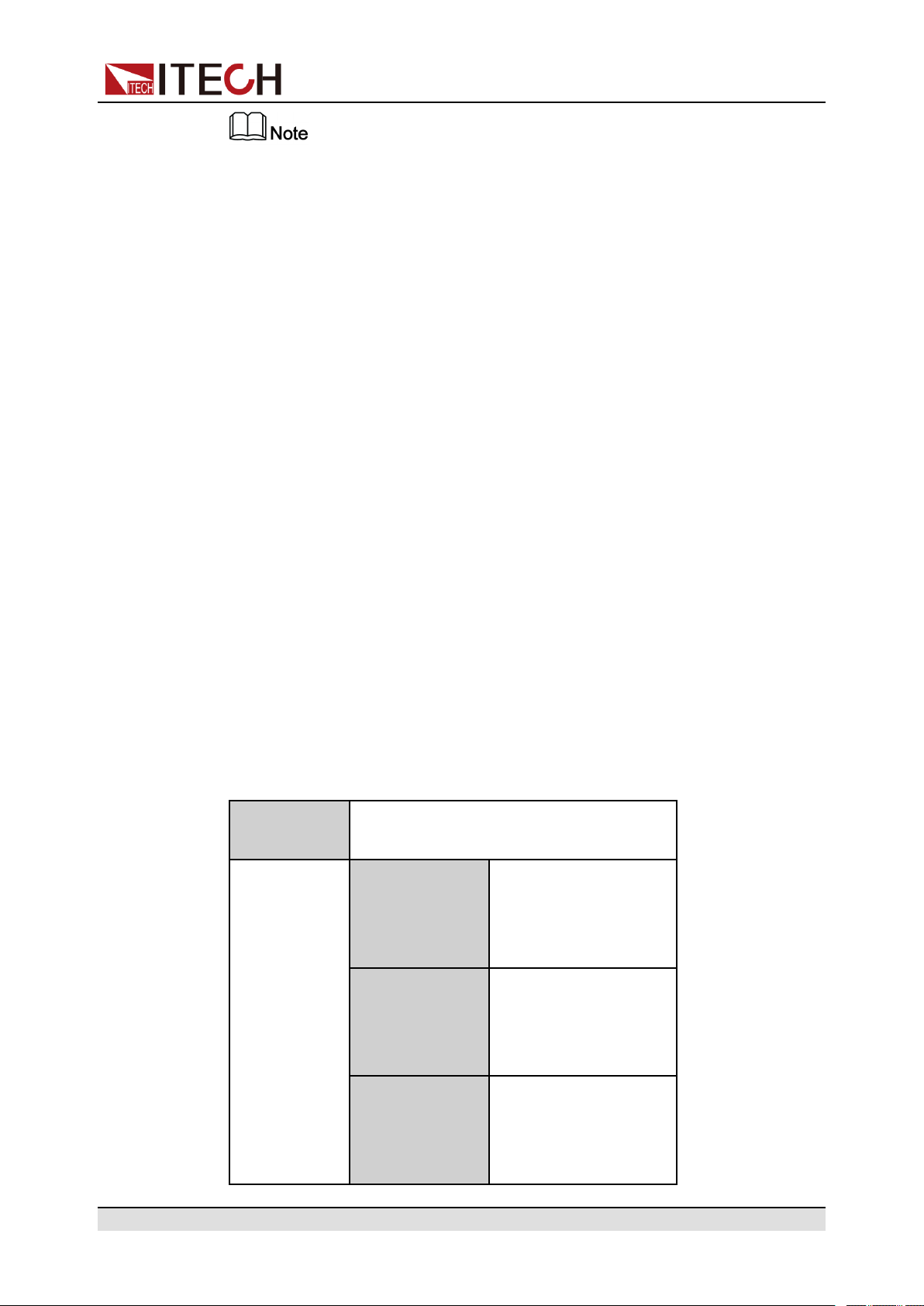
The trigger method of the vehicle waveform is consistent with the trigger
ООО "Техэнком" Контрольно-измерительные приборы и оборудование www.tehencom.com
method of the List function, that is, the List trigger source is also effective for
the vehicle waveform.
Stop the Vehicle Waveform Running
If you want to stop during the vehicle waveform output, you can do the following:
Press the composite keys [Shift]+[I-set] (Function) on the front panel to enter
the function menu.
At this point, the interface will prompt whether to stop the running of the Function (FUNCTION STOP?), you can press the Left/Right key to select Yes, then
the current running will be stopped, and the Function menu item will be dis-
played, you can re-enter the Function menu for editing; if No is selected, it
means that the current running will not be stopped, and the main interface of the
system is displayed.
Power Supply Function
4.6.3.1 Automotive Starting Waveform
The IT6000C series power supply has built-in 12V or 24V DIN40839 waveform.
This test verifies the behavior of a DUT during and after cranking. This waveform can reproduce the voltage curve for automotive power network confirms to
DIN40839 standard, thus facilitating quick call by customers.
For automotive startup voltage waveform, the startup voltage can also be set
based on customers’ requirements. In this way, the user can create waveform
between 8V to 32V.
DIN40839
Evaluation of automotive starting
waveform
Select the automotive
12V
24V
starting waveform with
a starting voltage of
12V.
Select the automotive
starting waveform with
a starting voltage of
24V.
The user customizes
User-defined
Copyright © Itech Electronic Co., Ltd.
the starting voltage of
the automotive starting
waveform.
88
Page 100

DIN40839 for 12V System
ООО "Техэнком" Контрольно-измерительные приборы и оборудование www.tehencom.com
Steps Voltage (V) Current(A) Width(mS) Slope(mS)
1 4.5 60 15 5
2 6 60 2000 5
3 12 60 T 10
V=8.00V
Power Supply Function
User-defined voltage value
DIN40839 for 24V System
Steps Voltage (V) Current(A) Width(mS) Slope(mS)
1 8V 60 50 10
2 12V 60 2000 5
3 24V 60 T 10
Copyright © Itech Electronic Co., Ltd.
89
 Loading...