

Page 1
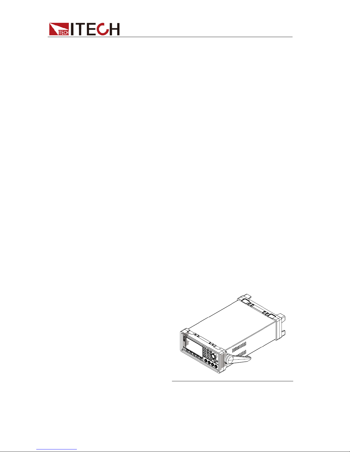
Internal Resistance Tester
IT5101 User Manual
Model:IT5101/IT5101E
Version:V1.0
Page 2

Notices
© Itech Electronic, Co., Ltd. 2016
No part of this manual may be
reproduced in any form or by any means
(including electronic stor age and
retrieval or translation into a foreig n
language) without prior permission and
written consent from Itech Electronic,
Co., Ltd. as governed by international
copyright laws.
Manual Par t Number
IT5101-402530
Revision
1st Edition: May 26, 2016
Itech Electronic, Co., Ltd.
Trademarks
Pentium is U.S. registered trademarks
of Intel Corporation.
Microsoft, Visual Studio, Windows and
MS Windows are registered trademarks
of Microsoft Corporation in the United
States and/or other countries and
regions.
Warranty
The materials contained in this
document are provided “as is”, and
is subject to change, without prior
notice, in future editions. Further, to
the maximum extent permitted by
applicable laws, ITECH disclaims
all warrants, either express or
implied, with regard to this manual
and any information contained
herein, including but not limited to
the implied warranties of
merchantability and fitness for a
particular purpose. ITECH shall not
be held liable for errors or for
incidental or indirect damages in
connection with the furnishing, use
or application of this document or of
any information contained herein.
Should ITECH and the user enter
into a separate written agreement
with warranty terms covering the
materials in this document that
conflict with these terms, the
warranty terms in the separate
agreement shall prevail.
Technology Licenses
The hardware and/or software
described herein are furnished under a
license and ma y be used or copied only
in accordance with the terms of such
license.
Restricted Rights Leg end
Restricted permissions of the U.S.
government. Permissions for software
and technical data which are authorized
to the U.S. Government only include
those for custom provision to end users.
ITECH provides this customary
commercial license in software and
technical data pursuant to FAR 12.211
(Technical Data) and 12.212 (Computer
Software) and, for the Department of
Defense, DFARS 252.227-7015
(Technical Data – Comm erci a l Items)
and DFARS 227.7202-3 (Rights in
Commercial Computer Software or
Computer Software Documentation).
Safety Notices
A CAUTION sign denotes a
hazard. It calls attention to an
operating procedure or practice
that, if not correctly performed
or adhered to, could result in
damage to the product or loss of
important data. Do not proceed
beyond a CAUTION sign until
the indicated conditions are fully
understood and met.
A WARNING sign denotes a
hazard.
It calls attention to an
operating procedure or practice
that, if not correctly performed
or adhered to, could result in
personal injury or death. Do not
proceed beyond a WARNING
sign until the indicated
conditions are fully understood
and met.
NOTE
A NOTE sign denotes important
hint. It calls attention to tips or
supplementary information that
is essential for users to refer to.
Page 3
IT5101 User Manual
Copyright© Itech Electronics Co ., Ltd. i
Quality Certification and Assurance
We certify that IT5101 internal resistance tester meets all the published
specifications at time of shipment from the factory.
Warranty
ITECH warrants that the product will be free from defects in material and
workmanship under normal use for a period of one (1) year from the date of
delivery ( except those descri bed in the Limitation of Warranty below).
For warranty service or repair, the product must be returned to a service center
designated by ITECH.
The product returned to ITECH for warranty service must be shipped
PREPAID. And I TECH will pay for return of the product to customer.
If the product is returned to ITECH for warranty service from overseas, all
the freights, duties and other taxes shall be on the account of customer.
Limitation of Warranty
This War ranty will be rendered invalid if the product is:
Damaged resul t i ng f rom cu sto mer-w i r ed cir cui t s or cust o mer-s uppl i ed par t s
or accessories;
Modified or repaired by customer without authorizati on;
Damaged resulting from customer-wired circuits or use in an environment
not designated by us;
The product model or serial number is altered, deleted, removed or made
illegi ble by customer;
Damaged as a result of accidents, including but not limited to lightning,
moisture, fire, improper use or negligence.
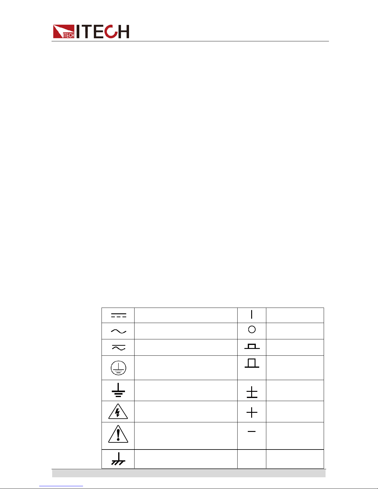
Safety Symbols
Direct current
ON (power)
Alternating current
OFF (power)
Both direct and alternating current
Power-on stat e
Chassis (earth ground) symbol.
Power-off state
Earth (ground) termi nal
Reference
terminal
Caution
Positive terminal
Warning (refer to this manual for
specific Warning or Caution
information)
Negati ve terminal
A chassis terminal
-
-
Page 4

IT5101 User Manual
Copyright© Itech Electronics Co ., Ltd. ii
Safety Precautions
The following safety precautions must be observed during all phases of
operation of this instrume nt. Failure to compl y wit h these pr ecaut i ons or sp eci fic
warnings elsewhere in this manual will constitute a default under safety
standards of design, manufacture and intended use of the instrument. ITECH
assumes no l iability for the customer’s failure t o comply with these preca utions.
Do not use the instrum ent if it is damaged. Before operation, check
the casing to see whether it cracks. Do not operate t he instrument in
the presence of inflammable gasses, vapors or du sts.
The internal resistance test er is provided with a three-cor e pow er line
during delivery and should be connected to three-core junction b ox.
Before operation, be sure t hat the internal resistance tester is well
grounded. M ake sure to use the power cord supplied by ITEC H.
Check all marks on t he instrumen t before connecting the instrument
to power supply.
Use electric wires of appropriate load. All loading wires should be
capable of b earing maximum short-circuit of electronic load without
overheat ing. If th ere are multi p le loads, each pai r of the load power
cord must be carr y out t he f ull rat ed short -ci rcui t out put cur r ent of the
power securel y.
Ensure the voltage fl uct uati on of mai ns supply i s less t han 10% of the
working voltage range in o rder to reduce risks of fire and ele ctric
shock.
Do not install alt ernative parts on the inst rument or per form any
unauthorized modifi cation.
Do not use the instrument if the detachable cover is removed or
loosen.
To prevent the possibility of accidental injuries, be sure to use the
power adapter supplied by the manufacturer only.
We do not accept responsibility for any direct or indi rect financial
damage or loss of profit that might occur when using the instrument.
This instrument is used for industrial purposes. Do not apply this
product to IT power supply system.
Never use the instrument with a life-support system or any other
equipment subject to safety requirements.
Failure to use the i n strument as directed by the manufacturer may
render its protective features void.
Always clean the casing w ith a dry cloth. Do not clean the internals.
Make sure the vent hole is alway s unblocked.
Environmental Conditions
The instrument is designed for indoor use and an area with low condensation.
The table below shows the general environmental requirements for the
instrument.
Environmental Conditions
Requirements
Operating tem perature
0°C to 40°C
Page 5

IT5101 User Manual
Copyright© Itech Electronics Co ., Ltd. iii
Operating humidity
20%-80% (non-condensation)
Storage temper ature
-20°C to 70 °C
Altitude
Operating up to 2,000 meters
Installation category
II
Pollution degree
Pollution degree 2
Note
To make accurate measurements, allow the instrument to warm up for 30 min.
Regulatory Markings
The CE mark indicates that the product
complies with all the relevant European
legal directives. The specific year (if any)
affixed refers to the year when the design
was approved.
The instrument complies with the WEEE
Directive (2002/96/EC) marking
requirement. This affix product label
indicates that you must not discard the
electrical/electronic product in domestic
househol d waste.
This symbol indicates the time period
during which no hazardous or toxic
substances are expected to leak or
deteriorate during normal use. The
expected useful life of the product is 10
years. The product can be used safely
during the 10-year Environment Friendly
Use Period (EFUP). Upon expiration of
the EFUP, the product must be
immediately recycled.
Waste Electrical and Electronic Equiment (WEEE)
Directive
2002/96/E C Waste Electrical and Electronic Equipment
(WEEE) Directive
This product complies with the WEEE Directi ve (2002/96/EC)
marking requirement. This affix product label indicates that you
must not discard the el ectrical/electronic product in domestic
househol d waste.
Product Category
With reference to the equipment classifications described in the
Annex 1 of the WEEE Direct ive, this instrument i s classified as
a “Monitoring and Control Instrument”.
To return thi s unwant ed i nst rument , cont a ct y our near est IT ECH
office.
Page 6

IT5101 User Manual
Copyright© Itech Electronics Co ., Ltd. iv
Compliance Information
Complies with the essential requirements of the following applicable European
Directives, and carries the CE marking accordi ngly:
Electromagnetic Compatibility (EMC) Directive 2014/30/EU
Low-Voltage Directive (Safety) 2014/ 35/EU
Conforms with the following product standards:
EMC Standard
IEC 61326-1:2012/ EN 61326-1:2013 ¹²³
Reference Standards
CISPR 11:2009+A1:2010/ EN 55011:2009+A1:2010 (Group 1, Class A)
IEC 61000-4-2:2008/ EN 61000-4-2:2009
IEC 61000-4-3:2006+A1:2007+A2:2010/ EN 61000-4-3:2006+A1:2008+A2:2010
IEC 61000-4-4:2004+A1:2010/ EN 61000-4-4:2004+A1:2010
IEC 61000-4-5:2005/ EN 61000-4-5:2006
IEC 61000-4-6:2008/ EN 61000-4-6:2009
IEC 61000-4-11:2004/ EN 61000-4-11:2004
1. The product is intended for use in non-residential/non-domestic environments. Use of the
product in residential/domestic environments may cause electromagnetic interference.
2. Connection of the instrument to a test object may produce radiations beyond the specified
limit.
3. Use high-performance shielded interface cable to ensure conformity with the EMC standards
listed above.
Safety Standard
IEC 61010-1:2010/ EN 61010-1:2010
Page 7

IT5101 User Manual
Copyright© Itech Electronics Co ., Ltd. v
CONTENT
Quality Certification and Assurance .........................................................................................................................i
Warranty .................................................................................................................................................................i
Limitation of Warranty ............................................................................................................................................i
Safety Symbols ........................................................................................................................................................i
Safety Precautions .................................................................................................................................................. ii
Environmental Conditions ...................................................................................................................................... ii
Regulatory Markings ............................................................................................................................................. iii
Waste Electrical and Electronic Equiment (WEEE) Directive ................................................................................... iii
Compliance Information ........................................................................................................................................ iv
Chapter1 Inspection and Installation ............................................................................................................... 1
1.1Verifying the Shipment ..................................................................................................................................... 1
1.2 Optional Accessories ....................................................................................................................................... 1
1.3 Instrument Size Introduction ........................................................................................................................... 5
1.4Dimension ........................................................................................................................................................ 5
1.5 Adjusting the Handle ....................................................................................................................................... 7
1.6 Removing the Handle ...................................................................................................................................... 7
1.7 Rack Mounting ................................................................................................................................................ 8
1.8 Connecting the Power Cord ............................................................................................................................. 8
1.9 Connecting Test Lines ( Optional) ..................................................................................................................... 8
Chapter2 Quick Start ...................................................................................................................................... 10
2.1Brief Introduction ........................................................................................................................................... 10
2.2 Features ........................................................................................................................................................ 10
2.3 Front Panel Introduction ................................................................................................................................ 11
2.4 Introduction to keyboard ............................................................................................................................... 11
2.5 Screen Indicator Lamps Description ............................................................................................................... 12
2.6 Rear Panel Introduction ................................................................................................................................. 12
2.7 Power-on Selftest .......................................................................................................................................... 12
Chapter3 Function and Features .................................................................................................................... 15
3.1 Range Setting ................................................................................................................................................ 15
3.2Sampling Rate Setting ..................................................................................................................................... 16
3.3 System Menu ................................................................................................................................................ 16
3.4Reset System .................................................................................................................................................. 18
3.5Frequency Filter Setting .................................................................................................................................. 19
3.6 Alarm Mode Setting ...................................................................................................................................... 20
3.7Compare Function .......................................................................................................................................... 21
3.8 Calculate Function ......................................................................................................................................... 22
3.9Average Function Setting ................................................................................................................................ 23
3.10Trigger Function Setting ................................................................................................................................ 24
3.11Statistics On/Off Setting ............................................................................................................................... 25
3.12Save/Recall Function .................................................................................................................................... 26
3.13 Screen Capture Function ............................................................................................................................. 27
3.14Statistics Function ........................................................................................................................................ 27
3.14.1View Statistic Results ........................................................................................................................ 28
3.14.2Display List ......................................................................................................................................... 28
3.14.3Display Normal Distribution Plot ....................................................................................................... 29
3.14.4Save/Recall Measureme nt Data ...................................................................................................... 29
3.15 Zero-Adjust Function ................................................................................................................................... 30
3.16 External Control(EXT I/O) ............................................................................................................................. 31
3.17 ERR Output .................................................................................................................................................. 35
3.18 Setting EOM Signal ...................................................................................................................................... 36
3.19 Timing Chart ................................................................................................................................................ 36
Chapter4 Routine Maintenance ..................................................................................................................... 38
Page 8

IT5101 User Manual
Copyright© Itech Electronics Co ., Ltd. vi
4.1 Self-test ......................................................................................................................................................... 38
4.2 Routine Maintenance .................................................................................................................................... 38
4.3 Contact ITECH Engineer ................................................................................................................................. 38
4.4 Return for Repair ........................................................................................................................................... 40
Chapter5 Remote Control .............................................................................................................................. 41
5.1 USB Interface ................................................................................................................................................. 41
5.2 GPIB Interface ............................................................................................................................................... 41
5.3 LAN Interface ................................................................................................................................................. 41
Chapter6 Specification ................................................................................................................................... 42
6.1 Main technical parameters ............................................................................................................................ 42
6.2 Supplemental characteristics ......................................................................................................................... 44
Page 9
Inspection and Installation
Copyright© Itech Electronics Co., Ltd. 1
Chapter1 Inspection and Installation
1.1Verifying the Shipment
Unpack the box and check the contents before operating the instrument. If
wrong items have been deliv ered, if items are missing, or if there is a defect
with the appearance of the items, contact the dealer from whi ch you purchased
the instr ume nt immediately. The package contents include:
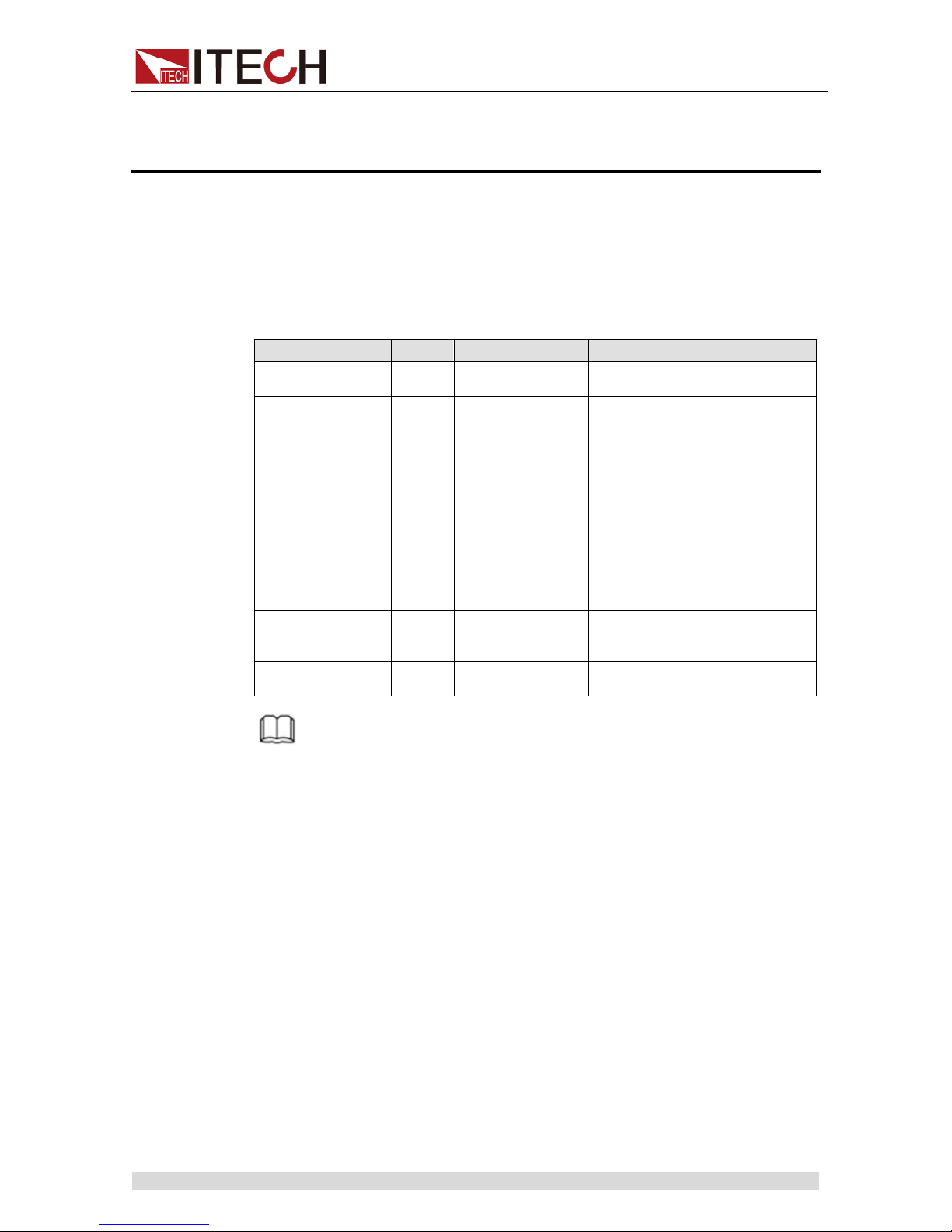
Checklist of Package Contents:
Item
Qty.
Model
Remarks
Internal
Resistance Tester
x1
IT5101/IT5101E
-
Power Cord
x1
IT-E171/IT-E172/
IT-E173/IT-E174
User may select an appropriate
power cord that matches the
specificat ions of power socket
used in the area. See the
Section
Connecting the Power Cord
for
details.
USB cable
x1
-
This accessory is selected
when the USB interface is used
for starting up rem ote
operation.
CD
x1 - It contains User’s Manual,
Programming Guide and other
user documentations.
Ex-factory Test
Report
x1 - It is the test report of the
instrument before delivery.
NOTE
Upon verification of the shipment, keep the package and relevant contents thereof in a
safe place. When returning the instrument for warranty service or repair, the specified
packing requirements shall be met.
1.2 Optional Accessories
IT5100 series internal resistance tester is supplied with the following optional
accessories (sold sep arately ):
Rack Mount Kit
This accessor y i s used t o mo unt t he i nst ru ment to sp eci al rack. ITECH provides
two models of rack mount kits: IT-E151 and IT-E151A. For detailed installation
process, refer to 1.7 Rack Mounting.
Test Lines
ITECH provides alone-sold test lines for professional measure. Test lines in
sold and related introduction are shown below. All lengths in the figure are in
mm.
IT-E601 IT-E601 Pin type lead (Under DC600V)
Page 10

Inspection and Installation
Copyright© Itech Electronics Co., Ltd. 2
Either for plane contacts or relay terminals that are not easy to clamp or small
objects like connectors, you j ust n ee d t o touc h the t est l i nes a gai nst the D U T f or
four-terminal measurement. The meter pen can be directly unscrewed for
changing For detailed length specif ication, see the figure above.
The central probe of the meter pen is Sense and the outer cylinder probe is
Source terminal. The schematic diagram is as shown below.
IT-E602 Large clip type lead for small component test ( Under DC600V)
It can be used to cl amp thick cylinder parts of DUT and is easy for operation. To
take four-terminal mea surement, directly clamp the DUT terminals. For det ailed
length specification, see the figure above.
The upper-jaw pr obe of al li gat or cli p i s Source terminal and t he low er -jaw probe
is Sense terminal. The schematic diagram is as shown below.
Page 11

Inspection and Installation
Copyright© Itech Electronics Co., Ltd. 3
IT-E603 Pin type lead for high-voltage bat tery test (Under DC600V)
The test lines are needle-type test lines with high dielectric strength designed
for DC300V (CATI) four-terminal structure, especially for high-voltage battery
packs or batteries with high docking ground potential. Two parallel pins are
designed at top for measurement through stable touch. The meter pins are
changeabl e. For detai led length specifications, see the figure above.
In the two meter pens, the one at the short corner side is Sense terminal and
the other is Source terminal. The schematic diagram is as s hown below.
IT-E604 4-terminal testing lead (Under DC600V)
The four-terminal test lines can connect and test DUT intuitively and
conviniently.
The alligator clip is Source terminal and rubber plug is Sense terminal. The
schemati c diagram is as shown below.
Page 12

Inspection and Installation
Copyright© Itech Electronics Co., Ltd. 4
Zero adjustment board
For zeroing, you need ITECH IT-E605 zeroing plate. The front and back sides
of the zeroing plate are as shown below.
Front side:
IT-E601: wiring area for zeroing by IT-E601 testing lines.
Or, the user can directly insert the crown-head meter pen to the
corresponding wiring holes in IT-E601. The outer circle corresponds to
Source terminal and the inner core corresponds to Sense terminal. There
is no positive and negative difference.
IT-E602: wiring area for zeroing by IT-E602 testing lines.
Directly clamp wiring end of IT-E602 area with the alligator clip, where the
Source and Sense terminals correspond to the gold-plated areas at front
and back. Pay attention to positive and negative identifications.
IT-E603: wiring area for zeroing by IT-E603 testing lines.
Directly insert two probes to corresponding holes of Source and Sense
terminals. Ther e is no positive and negative difference.
Page 13

Inspection and Installation
Copyright© Itech Electronics Co., Ltd. 5
IT-E604: wiring area for zeroing by IT-E604 testing lines.
Connect the four terminals of the test line to wiring areas respectively
based on identifications on the gold-plated area. Pay attention to positive
and negative identi fications.
Back side:
IT-E602: wiring area for zeroing by IT-E601 testing lines. The test line has
alligat or clips. Directly clamp the clips to connect Source and Sense terminals.
1.3 Instrument Size Introduction
The instrument should be installed at well-ventilated and rational-s ized space.
Please sel ect appropr i at e sp ace for i nst all ati on based on t h e internal resistance
tester size.
1.4Dimension
the detail size of the internal resistance tester is shown as below.
Dimension:
width:226mm
Height:105.18mm
Depth:383.92mm
Dimension
Page 14

Inspection and Installation
Copyright© Itech Electronics Co., Ltd. 6
Page 15

Inspection and Installation
Copyright© Itech Electronics Co., Ltd. 7
1.5 Adjusting the Handle
The instrument is equi pped with a handle for user to easily carry and place i t.
The handle can be adjusted in three manners as shown in the figure below. To
adjust the handle, first pull out the handle gently toward the left and right sides
of the inst rument, and then rotate it slowly to i ts alignment key s.
1.6 Removing the Handle
To mount the instrument on a r ack, fi rst remove the handle from the instrument.
The handl e can be removed following the procedure s below:
1. Rotate the handle to the position as shown in the following figure.
Page 16

Inspection and Installation
Copyright© Itech Electronics Co., Ltd. 8
NOTE
The handle can be easily removed from the alignment hole and key between the
handle and the instrument.
2. Pull out the handle toward the left and rights sides of the instrument from
the alignment hole.
NOTE
When mounting or removing the handle, do not squeeze it too hard and mind your
hand.
1.7 Rack Mounting
IT5101 can be mounted on a standard 19” rack. ITECH provides user with
IT-E151/IT-E151A rack, as an optional mount kit. The detailed operation please
refer to t he U ser Manual of your mount kit.
1.8 Connecting the Power Cord
Before connecting the power cord, please ensure the power switch of the
instrument is turned OFF. Only use the power cord supplied as a standard
accessory. The range of working vot age is AC100V~ AC 240V.
A summary of connection pr ocedures is given below.
Select from the flowing Schedule of Power Cord Specifications an appropriate
power cord that matches the voltage for the area in which you use the
instrument. If the power cord included in the instrument you purchased does
not match the voltage, co ntact the dealer or manufacturer f or change.
China
IT-E171
United States &
Canada & Japan
IT-E172
Europe
IT-E173
England
IT-E174
1.9 Connecting Test Lines ( Optional)
To avoid burning out, be sure to conf irm that power voltage matches
with supply voltage.
To avoid electrical shock, bef ore testing, please make sure the
ratingvalues of the testing lines, and do not measure t he voltage that
higher than t he rating v alue.
To avoid battery short cir cuit , be sur e to check t hat t he te st l ine e nd is
not connected when connecting or disassembling the test line. When
the test li n e end is connected with battery, short circuit may cause
severe acci dent.
E
N L
E
L N
E
N L
E
L N
Page 17

Inspection and Installation
Copyright© Itech Electronics Co., Ltd. 9
The test lines are not standard accessories of the instrument and are for
individual sales. Please select them based on actual usage. This
instrument has a socket terminal for resistance measurement that is
independent from four t erminals For details, refer to test line intr oduction in
“1.1 Verifying the Shipment ”
1. Before connecting the test lines, be sure that the instrument Power is
in Of f position.
2. Please check that the top of four-terminal test line is not connect ed.
3. Connect the 4-terminal test line to the input terminal.
Connect the red test line to the red terminal, and the black test line to
the black ter minal. Match the red sense ▼ symbol at the fr ont panel to
the ▲ symbol of red test line, and the black sense▼ symbol to the ▲
symbol of black test line.
4. Connect the other side to the DUT terminal based on current test line
type.
Red
Black
Page 18

Quick Start
Copyr ight © Ite c h Electronics Co., Ltd. 10
Chapter2 Quick Start
This chapter introduces power-on check steps of IT5101 to ensure normal
start-up and usage under ini tialization st atus. This part also introduces the front
panel, the rear panel, and key functions of inter nal resistance tester, make sure
that you can quickly know the appearance, instruction and the key function
before you operate the instrument. Help you make better use of this series of
internal resistance tester.
2.1Brief Introduction
IT5100 series is a series of battery internal resistance testers with high
precisi on, hi gh r esol uti on and hi gh sp eed. I T 5100 ado pts AC 4-terminal sensi ng,
that means the tester can test internal resistance and voltage simultaneously
with high precision. Resistance resolution is down to 0.1 μΩ, voltage resolution
is 10 μV. Combined with external USB disk, IT5100 series can be widely applied
in cellphone lithium batteries, electric vehicle batteries and other batteries
inspecti on and sorti ng.
2.2 Features
IT5100 Series internal resistance tester is featured with:
Support resistance & voltage simultaneously test and display
Measure accuracy of battery i nternal resistance: 0.4%;
Measurement accuracy of battery voltage: 0.01%;
Maximum volt age meas ure ment resol ut i on: 10uV
Maximum resistance measurement resolution of IT5101 model: 0.1uΩ
Maximum resistance measurement resolution of IT5101E model: 10uΩ
Supports VISA / USBTMC/ SCPI prot ocol
Automatically judge whether test results exceed set specifications based
on the maximum/mi ni mum limitation of test parameters
Built-in GPIB, USB, LAN i nterfaces
Select multi-measurem ent speed based on requirements
Statistics calculation and data USB storage f unction
Software mo nitoring via computer
Software-based calibration
4.3 inch LCD s creen
Page 19
Quick Start
Copyr ight © Ite c h Electronics Co., Ltd. 11
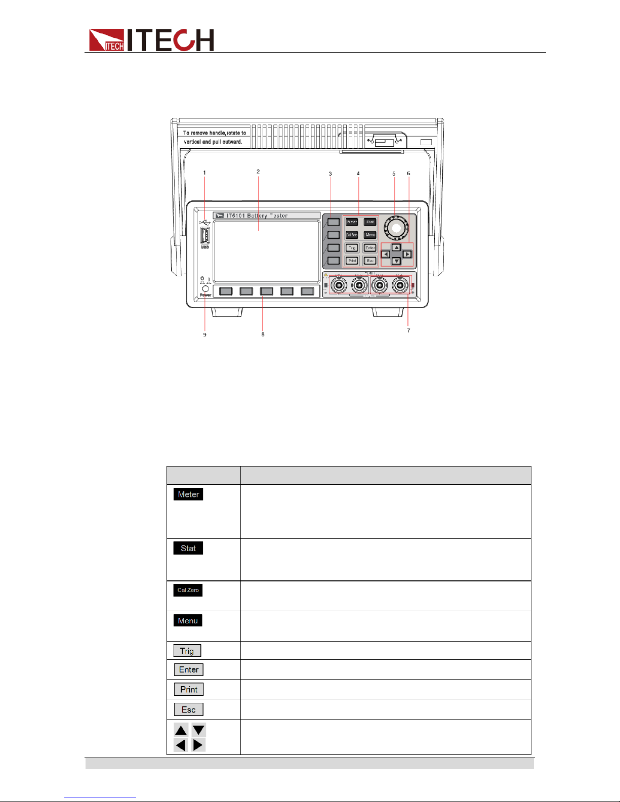
2.3 Front Panel Introduction
Schematic Diagr am of Front Panel of IT 5101 series internal resis tance test er is as
follow.
2.4 Introduction to keyboard
The functions of keys on the front panel of the IT5101 ser ies internal resistance
tester are shown in t he following table.
Key tag
Name and funct ion
Basic Measurement key When this key is pressed, the
measurement value
of voltage and resistance will be
displayed, and also displayed the config menu of
measurement.
Statistics key. When this key is pressed, the statistic
parameters (average, standard deviation) of measurement
data will be displayed.
Zero key. When this key is pressed, zeroing information will
be displayed.
Menu key, used for setting relevant measurement
parameters.
Used for manual trigger.
Enter key, used for confirming and saving the settings.
Used for sa ving screen images
Cancel/R eturn key
Up/Down key and Left/Right key
1 USB Interface
2 Display
3 Menu Ke ys
4 Functi on Keys
5 Setting knob
6 Arrow keys
7 Source terminals & Sense terminals
8 Menu Ke ys
9 Power Key
Page 20
Quick Start
Copyr ight © Ite c h Electronics Co., Ltd. 12
Key tag
Name and funct ion
Soft keys for correspon ding screen menu operations
Rotary knob: used for setting the value indicated by the cursor,
selecting the voltage and resistance range, adjusting the
waveform, etc.
2.5 Screen Indicator Lamps Description
IT5101 series internal resistance tester screen indicator lamps description as
follows:
Flag
Function Description
Mx+B statistic function ON
Insert USB p eriphery device
Key lock. Press this key to disable all the keys except
Esc; press Esc key again for 5s to unlock all other key s.
Compare function ON.
Average fun ction ON.
Statistic functi on O N .
Used for turning on remot e control
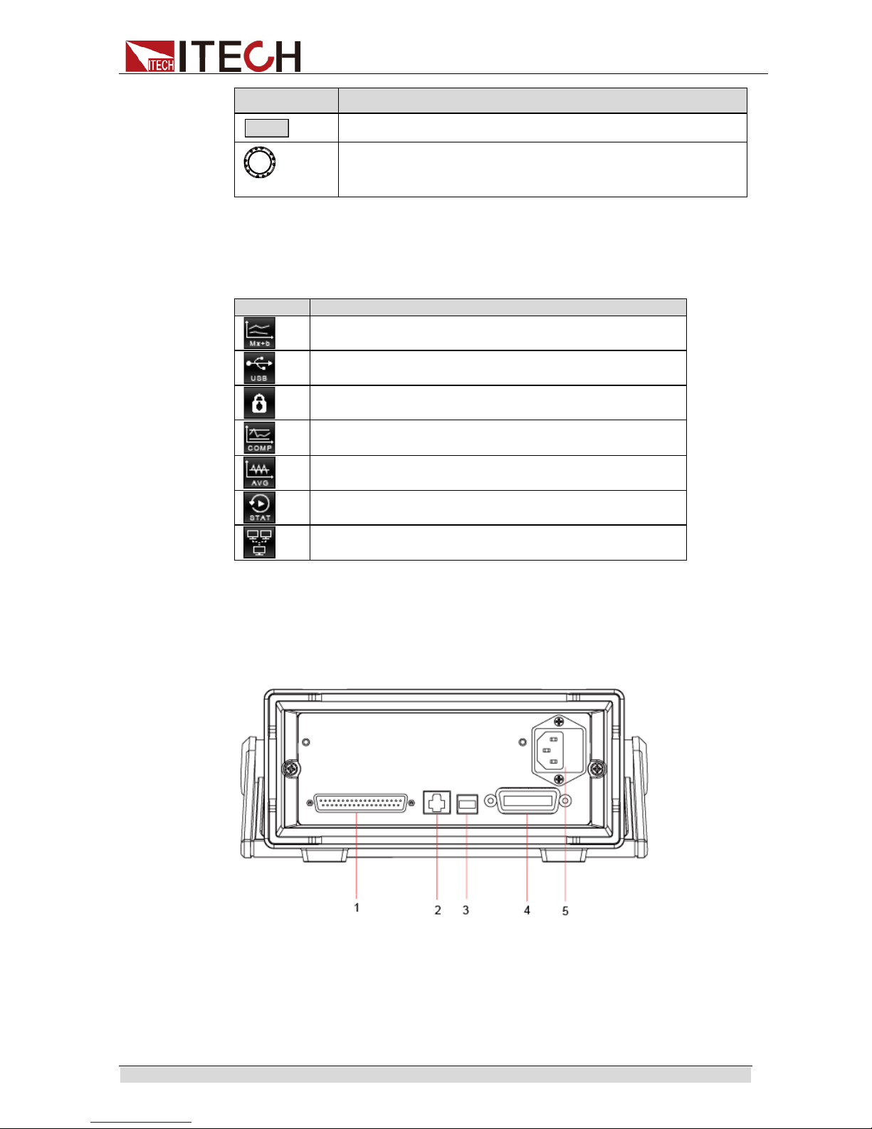
2.6 Rear Panel Introduction
Schematic diagram of rear panel of IT5101 series internal resistance tester is
as follow.
1 System I/O Interface
2 LAN Interface
3 USB Interface
4 GPIB Interface
5 AC Power Input
2.7 Power-on Selftest
A successful selft est indicates that the purchased power product meets delivery
standards and is available for normal usage.
Page 21
Quick Start
Copyr ight © Ite c h Electronics Co., Ltd. 13
Before operation, please confirm that you have fully understood the safety
instructions.
To avoid bur ning out, be sure to confirm that power voltage matches
with supply voltage.
The IT5101 supports 110V/220VAC input and no need t o sw itch.
Maximum voltage measurement r ange of instrument measurement
terminal: -300V-300V; max imum voltage between positiv e and
negative and ground: 300V. Do not connect overvoltage; otherwise,
the equipment will be burnt!
Be sure to connect the main power socket t o the power outl et of
protective grounding. Do not use termi nal board without protective
grounding. Before operation, be sure that the internal resistance
tester is well grounded.
Power Switch Introduction
User can press the power switch of IT5101 series internal resistance tester
directl y to turn on or turn off t he instrument .
The status of Power switch is as follows.
Selftest steps
The normal pow er-on process of t h e IT 51 01 s eries internal resist ance test er ar e
as follows:
1. Properly connect the power cord and press [Power] to power on the
instrument.
2. The internal resistance test er will take s elf-test and the instr ument will complete
inter-CPU communication test and reading a nd wr iting test of memory.
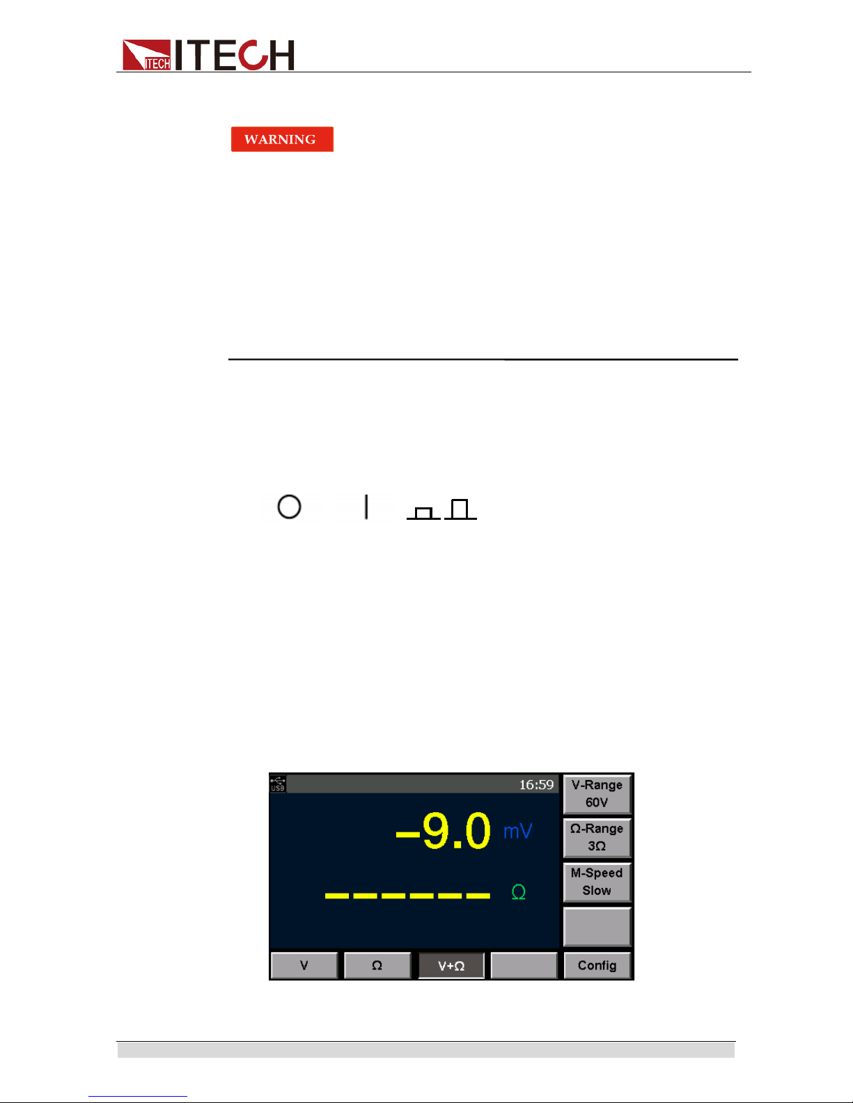
3.
After ini tialization, the LCD scree n displays the following information.
Off On
On Of f
Page 22
Quick Start
Copyr ight © Ite c h Electronics Co., Ltd. 14
Exception handling
If the internal resistance tester cannot start normally, please check as below
steps.
1. Check whether the pow er cord is correctly conne cted and confirm whether
the internal resistance tester is powered.
Correct wiring of pow er cord = > 2
Incorrect wir ing of power cord = > Re-connect the power cord and check
whether the exception is removed.
2. Check whether the power in On. Power key is under “” On status.
Yes = > 3
No = > Please check the Power key to start power and check whether the
exception is removed.
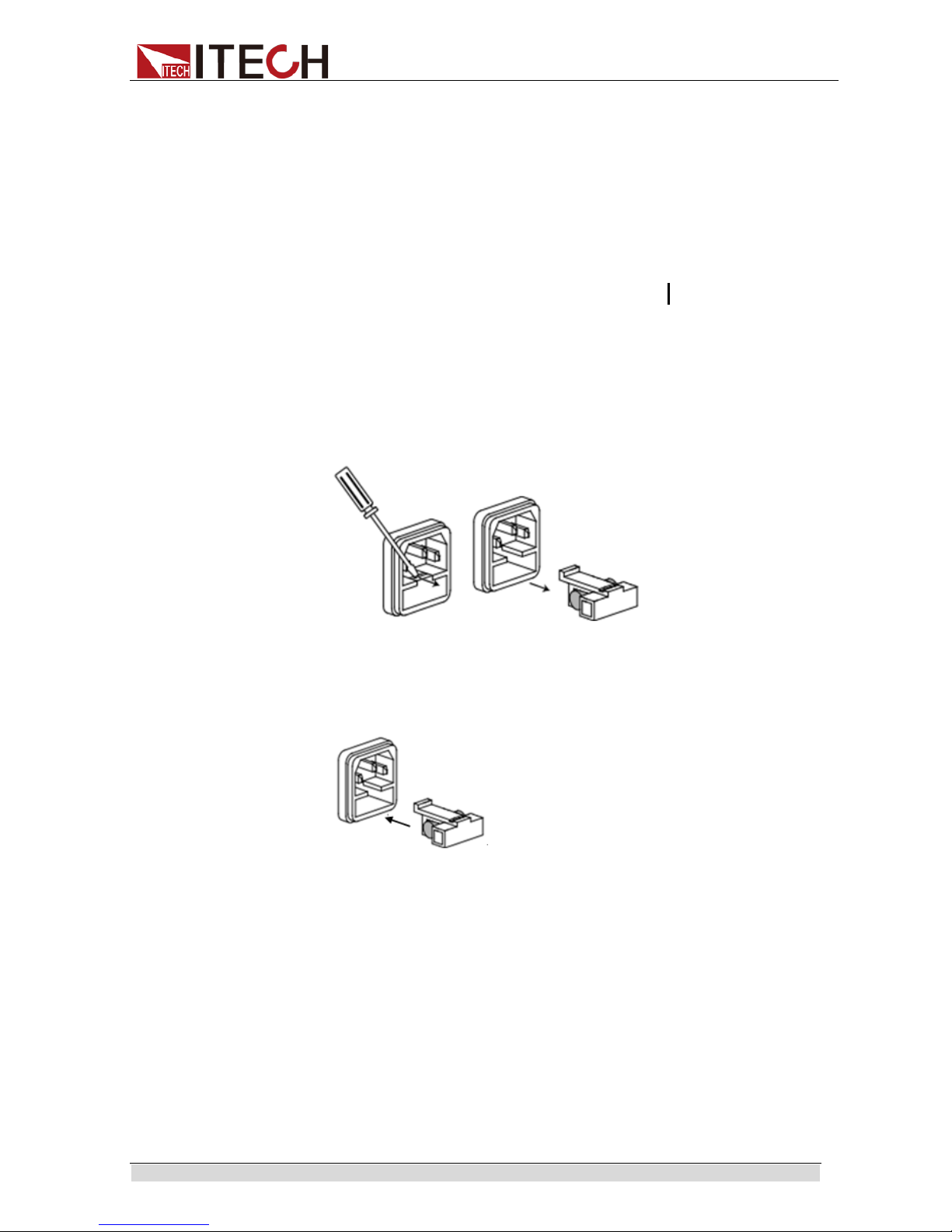
3. Check whether the fuse of internal resist ance tester is burned out.
If yes, change fuse. Det ailed steps:
i. First pull out the power cord, and then take out the fuse block from the
power cord jack with a small screw driver, as shown below:
ii. Have a visual inspect ion of the fuse t o see whet her it is burnt out; if yes,
replace it with another f use of the sa m e specification.
iii. After replacement, mount the fuse block to the original position, as
illust rated below:
Page 23
Function and Features
Copyr ight © Ite c h Electronics Co., Ltd. 15
Chapter3 Function and Features
This chapter describes in detail the use of the front-panel keys and shows how they
are used to accomplish internal resist ance t
ester operation.
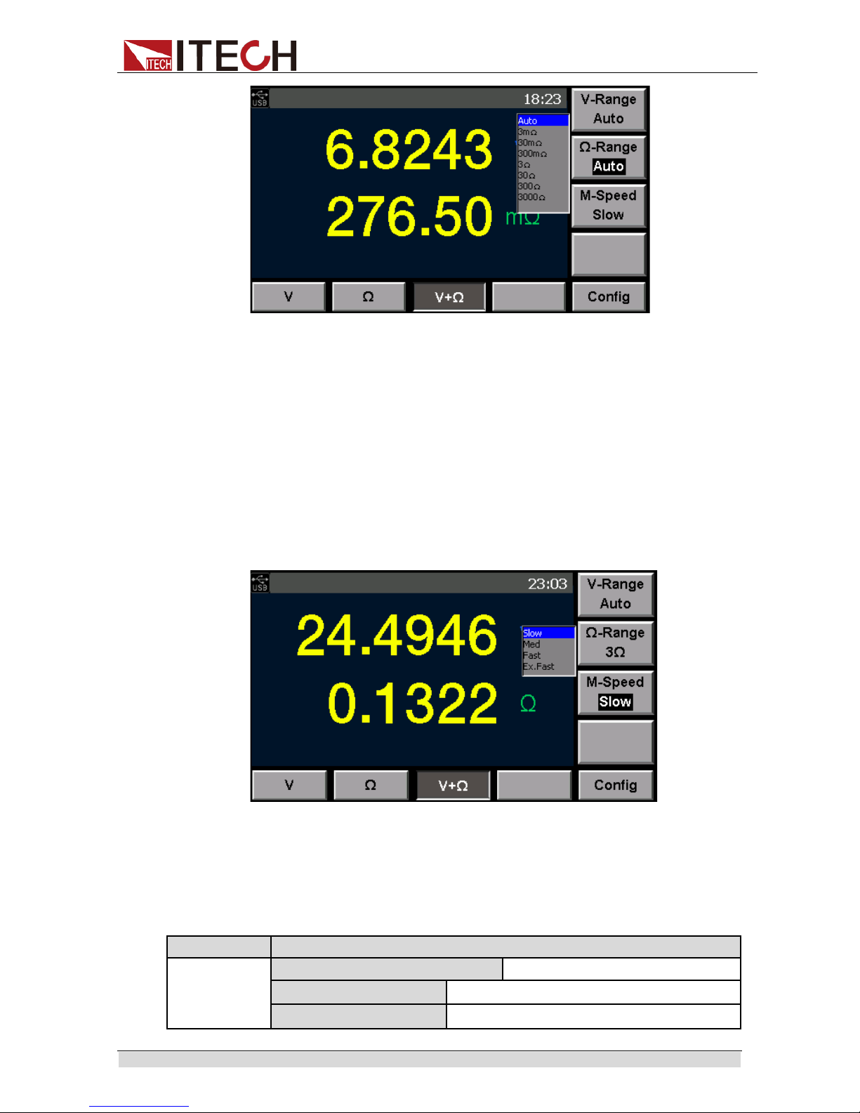
3.1 Range Setting
IT5101 Series internal resistance tester provides several ranges for measuring
voltage and internal resistance. If voltage/internal resistance scope of DUT is
known, appr opriate selection of range will improve measurement accuracy.
Voltage ranges of IT5101 Model: 6V, 60V and 300V; resistance ranges:
3mΩ, 30mΩ, 300mΩ, 3Ω, 30Ω, 300Ω and 3,000Ω. If voltage/internal
resistance scope is unknown, select Auto and the instrument will select
appropriate range auto m atically.
Voltage ranges of IT5101E Model: 6V, 60V and 300V; resistance ranges:
300mΩ and 3Ω. If voltage/internal resistance scope is unknown, select
Auto and the instrument will select appropriate range aut omatically.
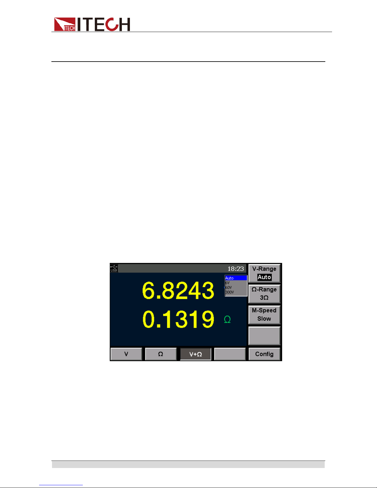
You can directly select the measurement range on current Measurement
interface. Detailed operations are as follows:
1. Press [Meter] key. Display current measurement statu s.
2. Press corresponding soft key of V/Ω/V+Ω to select current measurement
situation.
3. Based on dif ferent situations, press corre sponding soft key of “V-Range” and
“Ω-Range” to select appropriate measure range.
Voltage range (V-R ange) setting diagram is as shown below .
Resistance range (Ω-Range) setting dia gram of IT5101 Model is as shown
below.
Page 24
Function and Features
Copyr ight © Ite c h Electronics Co., Ltd. 16
3.2Sampling Rate Setting
When measuring voltage or internal resistance with the IT5101 internal
resistance tester, the user can directly select a sampl ing speed from four gears:
Slow, Med, Fast and EX. Fast on the current Measurement interface. Detailed
operation st eps are show n below:
1. Press [Meter] key. Display current measurement statu s.
2. Press corresponding soft key of V/Ω/V+Ω to select current measurement
situation.
3. Under different situations, select appropriate sampling speed by pressing
corresponding soft key of “M-Speed”.
3.3 System Menu
Menu function include system setup and system configuration, Press “MENU ”
on the front panel to set the system menu. You can set the following menu
items.
Menu System Menu
Sys Info
System information
Model
Product Model
Version
software
Version
Page 25

Function and Features
Copyr ight © Ite c h Electronics Co., Ltd. 17
SN
Series Nu mb er
Cal Info
Calibration information
MAC Address
Network hardware address
Sys Set
System Setting
Beeper
Setting the buzzer function
Brightness
Setting the screen brightness.
Data
Setting system date: Year/ Mont h/Day
Time
Setting system time: Hour/Minute/Second
Config
System Conf iguration
Filter Freq
Setting the filter frequency
Alarm Set
Setting the mode of alarm
Err Out
Setting Err output mode
EOM Mode
Setting th EOM signal
Pulse Time
Setting the pulse time. It is effective when
“EOM Mode” set to “Pul se”
Comm Set
Communication configuration
USB
Type B
Connect
Select the USB communication interface.
GPIB
Address
The address c an be set within 1-31
LAN
IP Mode IP mode:MANU/DHCP
Port Set Setting port
IP Addre ss Setting IP address
IP Mask Setting IP mask
Gate Way Setting gatew ay
Reset
Reset syst em
SetReset Reset the configurat ion of system
SysReset Reset all of system configurati on
Press [Menu] key. The system, by default, displays System Information; press
the corresponding soft key of [Sys Set] to enter System Parameter Setting
page for sett i ng t he configurations below. (The schematic di agr am ta kes IT 51 01
Model as an ex ample)
Page 26

Function and Features
Copyr ight © Ite c h Electronics Co., Ltd. 18
Key Sound Set (>Beeper)
This item can set the buzzer state.On option indicates that when you push
buttons,the buzzer will sound.OFF option indicates that the buzzer function is
disabled.Factory default i s On option.
Adjust Screen Brightness
The user can adjust current screen brightness as required. Select “Sys Set” in
the menu and set Brightness value from 0-9, representing different brightness.
The larger is the value, the brighter is the screen.
Set System Date and Time
Set system d ate and ti me through this menu.
Extend Range (special for IT5101E)
The internal resistance tester of IT5101E Model has only two small ranges: 3Ω
and 300mΩ. However, the user can extend the range to make it consistent with
that of IT5101 Model. To extend range, select “Sys Set” in the menu and input
key in “Extend Range” sett ing item. Press [Enter] to extend range.
Range Extend is cont rolled by a key. To extend range, the user must ask for the
key from ITECH.
3.4Reset System
In Menu interface, press corresponding soft key of Reset for system reset. The
user can select reset range and then reset the sy stem:
SysReset: system reset.
The syste m w ill reset the parameters below t o ex-factory set ting.
Parameters
Default setting
Measurement mode
V+R
V-Range
300V
Ω-Range
IT5101:3mΩ
IT5101E:Auto
M-Speed
Slow
Sys Set
Beeper:On
Brightness:6
Date:2016-01-01
Time:00:00:00
Comm Set
USB
Delay (C al zero)
0s
Filter Freq
50HZ
Alarm Set
Display
Err Out
ASync
EOM Mode
Hold
Page 27

Function and Features
Copyr ight © Ite c h Electronics Co., Ltd. 19
Parameters
Default setting
Compare
Off
Mx+B
Off
Trig Source
Auto
Trig delay
Off
Delay Time(Trig)
0s
Average
Off
Statistics Off
SetReset: C onfiguration reset.
Parameters
Default setting
Measurement mode
V+R
V-Range
300V
Ω-Range
IT5101:3mΩ
IT5101E:Auto
M-Speed
Slow
Compare
Off
Mx+B
Off
Trig Source
Auto
Trig delay
Off
Average
Off
Statistics
Off
3.5Frequency Filter Setting
To remove noise, the user needs to set frequency for the internal resistance
tester. This item in the Menu is used to set frequency value of the frequency
filter. The user can set the frequency value for the frequency filter to 50Hz or
60Hz. This frequency must be consistent with the internal resistance tester
frequency. Incorrect internal resistance tester frequency may lead to unstable
measurement value.
1. Press [Menu] key. Display current me asurement status.
2. Press correspondi ng soft k ey of [ Config] to set fi l t er fr equency, alarm, E rr out
and EOM mode.
3. Press Up/down key to select “Filter Freq” and select corresponding
frequency value. The frequency value should be consistent with AC input
frequency.
Page 28

Function and Features
Copyr ight © Ite c h Electronics Co., Ltd. 20
4. Press Up/down key to select configuration item to be set and press
corresponding soft key for setting. Press [Enter] to confirm the set values.
Otherwise, the set value will not be effective.
After setting, press [Esc] to return to Measurement interface; when you
directly press [Esc] to return but fail to press the [Enter] key for confirmation,
the setti ng fails.
3.6 Alarm Mode Setting
This item is used to set alarm mode of Compare function:
Display means to display alarm where the Meter Interface will display
compari son result, and not gives beep alarm;
Beeper means to sound alarm where the Meter interface only gives beep
sound but not displays comparison r esults;
All means display al arm + sound alar m.
When All is selected, VFD displays comparison results (In, Low or High), and
gives sound.
1. Press [Menu] key to enter Menu Setting page.
2. Press correspondi ng soft k ey of [ Config] to set filter frequency, alarm, Err out
and EOM mode.
3. Press Up/down key to select “Alarm Set” and select corresponding alarm
mode of comp arison results.
Page 29

Function and Features
Copyr ight © Ite c h Electronics Co., Ltd. 21
4. Press Up/down key to select configuration item to be set and press
corresponding soft key for setting. Press [Enter] to confirm the set values.
Otherwise, the setting will not be effective.
3.7Compare Function
The IT5101 Series internal resistance tester provides Compare function. The
user can turn on this function and set comparison range or basis, and display
comparison results during measurement. This will help the user to detect the
specifications of products in batch. The Compare function of Series IT5101
internal resistance tester is divided into Absolute Comparison and Relative
Comparison.
Notes
When voltage or resistance range is in “Auto” status, Compare function is disabled and
the “Compare” interface under “Config” interface cannot be opened.
Absolute Comparison allows the user to set upper and lower limits of the
voltage and resistance. The instrument will check whether the measured
value is within the preset range. The comparative results will either be
displayed on the screen in the form of alarm information or be given by
giving a beeper alarm. There are three alarm types: screen display +
beeper, only screen display or only beeper.
Relative Comparison all ows t he user t o set basic value and r el ati ve percent
of voltage and resistance. For example, if basic v alue and percent are set
to 100V and 30% respe cti vely, it indicates that i f the measured value i s 30%
higher/lower than the basic value, the system will alarm.
Setting Method
1. Press [Meter] key. Display Measurement page.
In the Meter interface, select required Measurement mode: V/R/V+R, and
select appropriate me asurement range.
2. Press corresponding soft key of [Config] and select related measurement
configurations.
3. By default, the system displays configuration items related to Compare
function, as shown below.
Compare: On or Off, used for turning on or off Compare function.
Mode: Compare mode. It is divided into Manual (output comparer results
only when EXT I/O MANU input is ON) and Auto (always output comparer
results) . Default mode: Auto.
Page 30

Function and Features
Copyr ight © Ite c h Electronics Co., Ltd. 22
Abs: during judgment of comparer, read absolute value of voltage
measurement. Even in reversed polarity of battery, comparison still can be
realized based on absolute value.
V Mode: set voltage compare mode: Absolute (H/ L) and Relati ve (Ref%).
R Mode: set resistance compare mode: Absolute (H/L) and Relative
(Ref%).
H: set upper limit of voltage or resistance.
L: set lower limit of voltage or resi stance.
R: set basic value in comparison.
%: set percent of volt age/r esi st ance val ue in compari son.
4. Press Up/down key to select configuration item to be set and press
corresponding soft key for setting. Set values through knob. Press [Enter] to
confirm the set values. Otherwise, the setti ng w ill not be effective.
After setting, press [Esc] to return to Measurement interface; when you
directl y press [Esc] to return but fail to press t he [Enter] key for confir mation,
the setti ng fails.
5. After Compare function is on, if Alarm mode is set to Display, the Meter
interface will display comparison results. If set to Beeper, the instrument will
give beep alarm. Meter interface of display mod e is as follows:
V-Comp: voltage compare result: Low (lower than compare range)/High
(higher than compare range)/In (within compare range)
R-Comp: resistance compare result: Low (lower than compare range)/High
(higher than compare range)/In (within compare range)
3.8 Calculate Function
The IT5101 Series internal resistance tester provides Calculate function, and is
applied for instrument calibration or linear amplification of measured data.
Suppose that the current measured voltage is x, the value after liner
amplification is M*x+B, where M and B are set values.
In general, Calculate function is used to calculate other physical values related
to voltage and resistance. Suppose that there is a linear relationship between
resistance and temperature: T=M*R+B, where T means temperature, R means
resistance, and M and B are set coefficients, through measurement of
resistance val ue, you can displ ay temperature r esult.
Set amplification factor and offset value followi ng the steps below:
1. Press [Meter] key. Display current measurement statu s.
Page 31

Function and Features
Copyr ight © Ite c h Electronics Co., Ltd. 23
2. Press corresponding soft key of [Config] and select corresponding
configurat ion items related to current measurement.
3. Press corresponding soft key of [Mx+B] for related settings of Calculate
function. As shown below.
Mx+B: On/O ff, used to set on/off of the Calculate function.
M Value(V): set multiple of voltage linear amplification. Setting range:
-1,000.0000~1,000.0000.
B Value(V): set offset of voltage linear amplification. Setting range:
-10,000.00000~10,000.0000.
M Value(V): set multiple of resistance linear amplification. Setting range:
-1,000.0000~1,000.0000.
B Value(V): set offset of resistance linear amplification. Setting range:
-10,000.00000~10,000.0000.
4. Press Up/down key to select configuration item to be set and press
corresponding soft key for setting. Set values through knob. Press [Enter] to
confirm the set values. Otherwise, the setting will not be effective.
After setting, press [Esc] to return to Measurement interface; when you
directl y press [Esc] to return but fail to press t he [Enter] key for confir mation,
the setti ng fails.
3.9Average Function Setting
To make measured value more accurate, the instrument provides Average
function, where the user can set total count of average as required. For
example, if the Count is set to 5, the measured result of each time will be the
average from 5 samplings.
1. Press [Meter] key. Display current measurem ent status.
2. Press corresponding soft key of [Config] and select corresponding
configurat ion items related to current measurement.
3. Press corresponding soft key of [Other Set] to set Filter, Average, Trigger
functions and Statistics On/Off.
4. Press Up/down key to select “Average” and select “On” to turn on Average.
Set total count of samplings for Average. As shown below.
Page 32
Function and Features
Copyr ight © Ite c h Electronics Co., Ltd. 24
Average: O n/Off, used to turn on or off Average function.
Count: set total count of sampli ngs for Average. Setting range: 2~16.
5. Press Up/down key to select configuration item to be set and press
corresponding soft key for setting. Set values through knob. Press [Enter] to
confirm the set values. Otherwise, the setti ng w ill not be effective.
After setting, press [Esc] to return to Measurement interface; when you
directl y press [Esc] to return but fail to press t he [Enter] key for confir mation,
the setti ng fails.
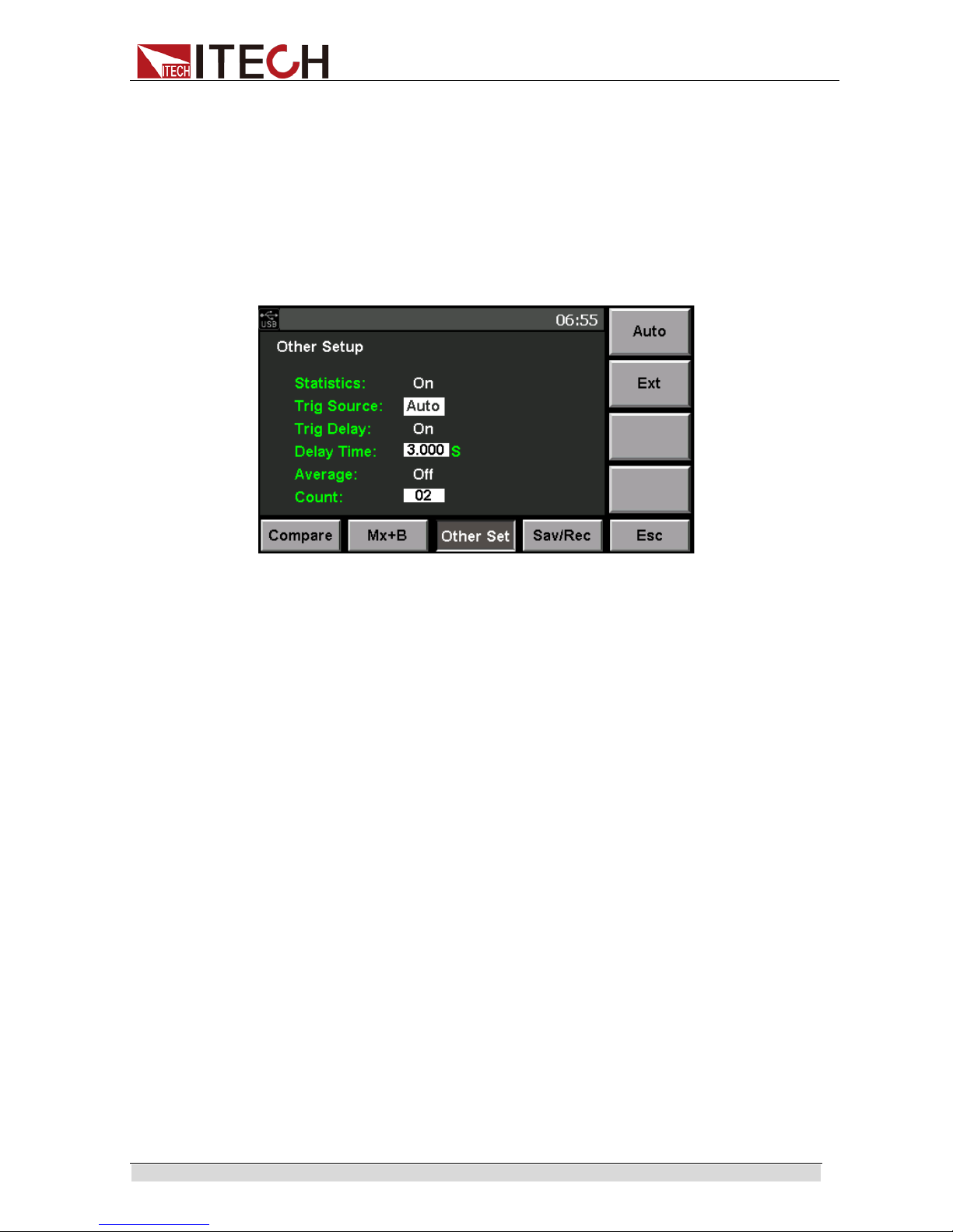
3.10Trigger Function Setting
Trigger Function Setting means to set the signal trigger mode for each
measurement. The instrument will sample and measure once after each trigger.
The user can set different trigger modes as required, i.e., triggering source
setting. U nder initial status of I T5101, the trigger source is Auto.
Trigger Source Setting
The user can s elect different trigger sources and set trigger waiting time. Select
“Trig Source” in the menu, and select corresponding soft key of trigger source
as required. IT5101 i nternal resistance tester has two trigger sources:
Auto
:the instrument will automatically generate trigger for auto
measurement.
Ext: external trigger, including keyboard [Trig], bus command trigger or
external trigger via the TRIG terminal input signal of EXT I/O port; when
TRIG signal is triggered once, the system will take 1 trigger and measure
once.
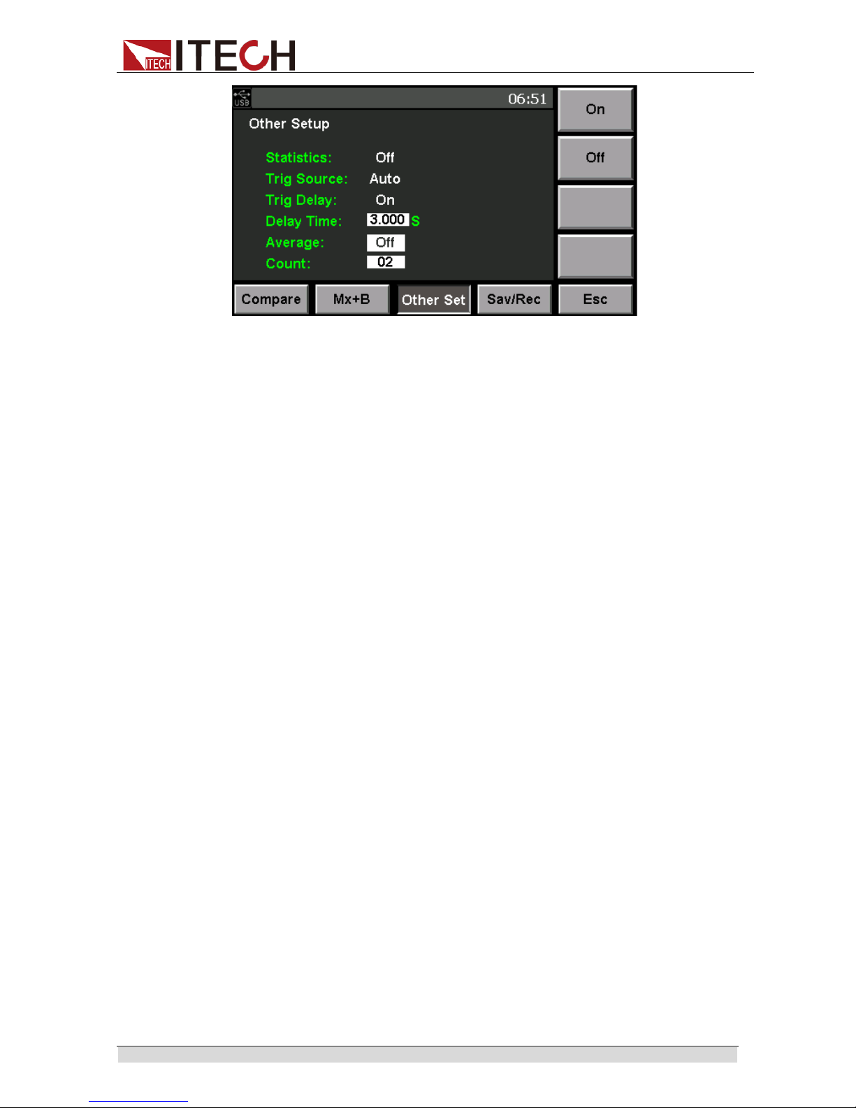
Trigger Delay Setting
The user can turn on/off Trigger Delay function and set the delay time from the
time to input tri gger si gnal to the time to st ar t measure as required. Thr ough this
function, the user can start measurement immediately after connection of DUT
or after measured value gets stable. Select this setting item and rotate t he knob
to set specific time val ue.
Setting Step
1. Press [Meter] key. Display current measurement statu s.
2. Press corresponding soft key of [Config] and select corresponding
Page 33
Function and Features
Copyr ight © Ite c h Electronics Co., Ltd. 25
configurat ion items related to current measurement.
3. Press corresponding soft key of [Other Set] to set Filter, Average, Trigger
functions and Statistics On/Off.
4. Press Up/down key to select “Trig Source” and select corresponding trigger
source. Press [Enter] for confi rmation.
5. Press Down key to select “Trig Delay” and set Delay Function On/off. Select
On and press [ Enter] for confirmation.
6. Press Down key to select “Delay Time” and set delay time through knob.
Press [Enter] for confirmation.
7. After setting, press [Esc] to return to Measurement interface; when you
directl y press [Esc] to return but fail to press t he [Enter] key for confir mation,
the setti ng fails.
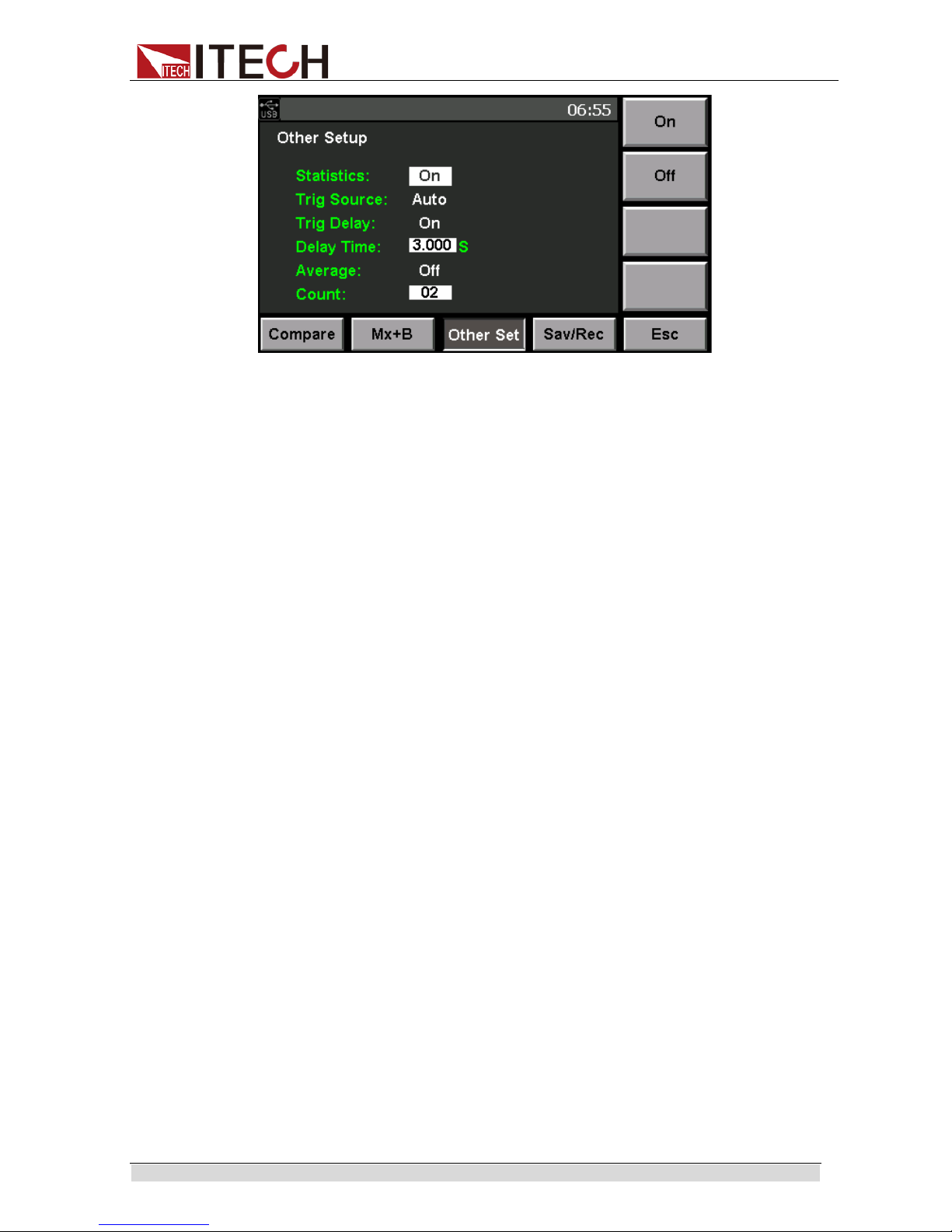
3.11Statistics On/Off Setting
In measurement, the user can conveniently turn on Statistic function in
Measurement Configuration menu. When this function is enabled, each trigger
of measurement will be recorded as one piece of statistic data For detailed
statistic information, refer to Stati stic Function. When the tri gger source i s set at
Auto (auto measurement by the instrument) auto Statistic function will not be
enabled so that the user needs to press [Trig] key to trigger Statistic
measurement. If Statist ic function is off, even if the [Start] is pressed, statistics
still fails.
1. Press [Meter] key. Display current measurement statu s.
2. Press corresponding soft key of [Config] and select corresponding
configurat ion items related to current measurement.
3. Press corresponding soft key of [Other Set] to set Average and Trigger
functions and Statistics On/Off.
4. Press Up/down key to select “Statistics” to turn on/off this function.
Page 34
Function and Features
Copyr ight © Ite c h Electronics Co., Ltd. 26
5. Press [Enter] to confirm the set values. Otherwise, the setting will not be
effective.
6. After setting, press [Esc] to return to Measurement interface; when you
directl y press [Esc] to return but fail to press t he [Enter] key for confir mation,
the setti ng fails.
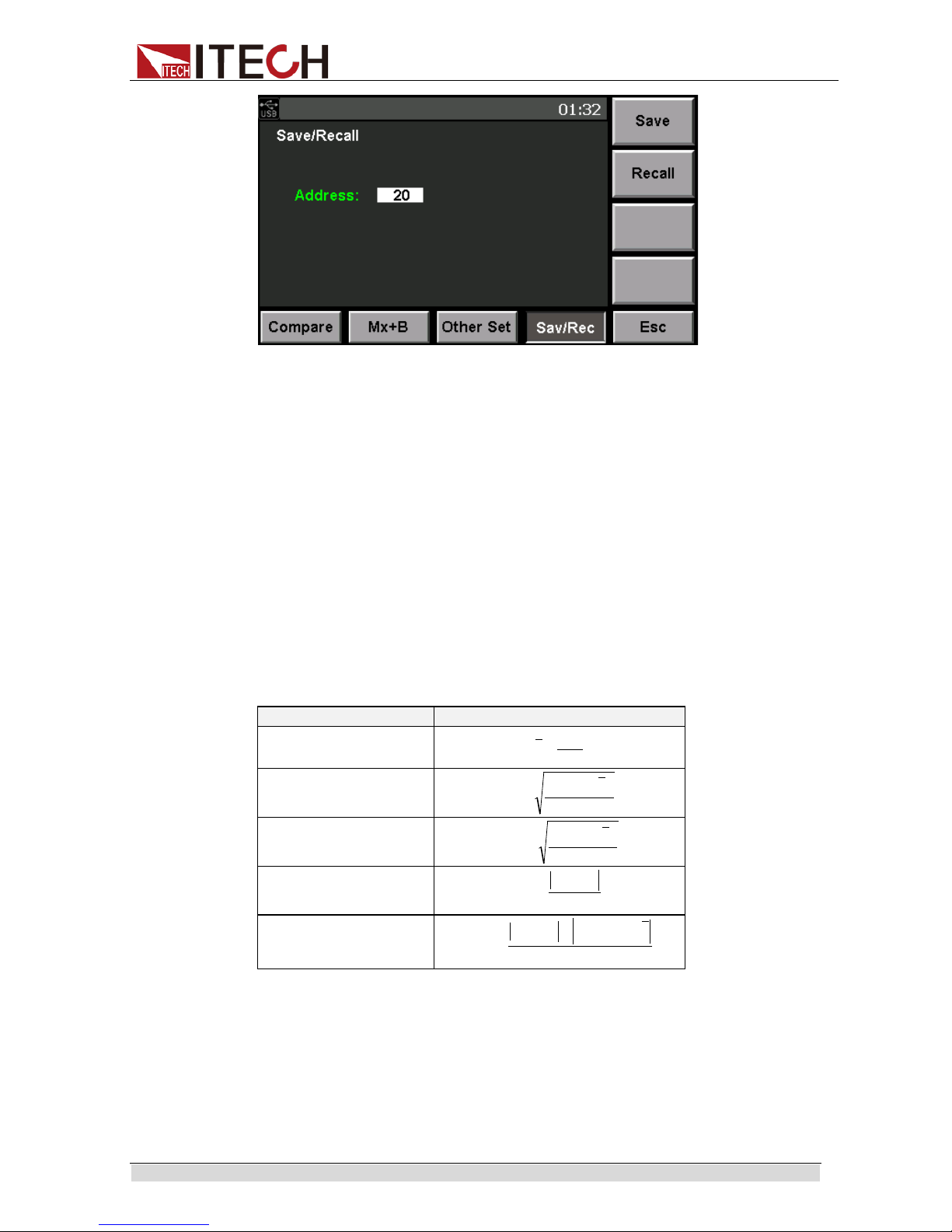
3.12Save/Recall Function
The user can save current measurement conditions in nonvolatile storage
space and recall these conditions from saving address. In IT5101 internal
resistance t est er, at maximum of 127 gr o ups of measur em ent c on di ti ons can b e
saved, including:
Measurement mode
Trig Source
V-Range&Ω-Range
Trig delay
M-Speed
Average
Filter Freq
Statistics
Compare
Mx+B
1. Press [Meter] key. Display current measurement statu s.
2. Press corresponding soft key of [Config] and select corresponding
configurat ion items related to current measurement.
3. Press corresponding soft key of [Sav/Rec] to save or recall measurement
conditions.
4. In “Address”, input address for saving or recalling. Setting range is 1-127.
5. Press corresponding soft key of [Save] or [Recall] for saving or r ecalling.
Page 35
Function and Features
Copyr ight © Ite c h Electronics Co., Ltd. 27
3.13 Screen Capture Function
The inter nal resi st ance test er has t h e fun c ti on of scre en c aptur e. I n sert t he US B
disk to USB i nt erf ace on fr ont panel, When [Print] on the front panel i s presse d,
the internal resist ance tester wi ll capture the present screen and save it into the
external storage devi ce.
3.14Statistics Function
The Statistics function enables batch record, statistics and analysis of batch
measurement results of battery. In Excel table, 1,000 pcs of measurement data
can be recorded. In IT5101 internal resistance tester, the user can take
statistics and analysis for measurement results, and calculate and display such
data as average, maximum value, minimum value, parent standard deviation,
sampli ng standard devi ation and pro cess capacity index .
The calculation formulas are as follows:
parameter
calculation formulas
Mean(x )
n
x
x
∑
=
Standard deviation of
population(σ)
n
xnx
n
∑
−
=
2
2
σ
Stand deviation of
sample(s)
1
2
2
1
−
−
=
∑
−
n
xnx
n
σ
Process capability
index( dispersion)
16−
−
=
n
p
LoHi
C
σ
Process capability
index(bias)
1
6
2
−
−+−−
=
n
p
xLoHiLoHi
KC
σ
In these for mul as, n r epre sents the number of valis dat a sa mples. Hi and Lo ar e
the upper an d lower thresholds of the comparator.
The process capability indices represent the quality achievement capability
vreated by a process, which is the breadth of thedispersion and bias of the
process’ quality. Generally, depending on the values of Cp and Cpk, process
capability is evaluat ed as follows:
Cp、CpK>1.33 Process capability is ideal
Page 36
Function and Features
Copyr ight © Ite c h Electronics Co., Ltd. 28
1.33≥Cp、CpK>1.00 Process capability is adequate
1.00≥Cp、CpK Process capability is inadequate
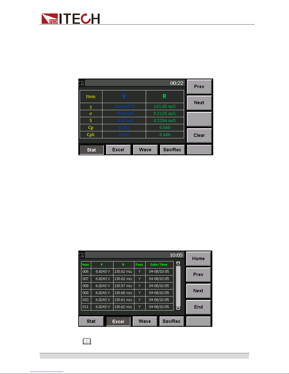
3.14.1View Statistic Results
Press [Start] key to enter Statistics page and view statistic information. In the
Statistics page, the user can display all statistic information through scrolling
display, or clear or sa ve/recall all statistic informati on.
Prev: page u p.
Next: page d own.
Clear: Clear statistic records. Press this soft key to clear records in Excel
and wave di splay at the same time.
The user can view such stati sti c items as
, σ, s, Cp, CpK, Max, Min, Index, etc.
3.14.2Display List
In Statistic Function page, select corresponding soft key of [Excel] to enter
Excel Table interface to view all current measurement data. The Excel displays
measurement serial number, measurement value, comparison results and
measurement time. In this interface, the user can select [Home], [Prev], [Next]
and [End] to view all data through scrolling display. In Statistics Function, at
maximum of 1, 000 data can be recorded.
Notes
Page 37
Function and Features
Copyr ight © Ite c h Electronics Co., Ltd. 29
Pass means to compare results;Y means that comparison is passed; N means that
comparison is not passed. When Compare function is Off and the “Pass“ in Statistics
information is also under Y status, for accurate comparison results, please turn on
Compare function at first and set related parameters. If the measured value exceeds
range, the N status will be displayed in regardless of whether Compare function is on or
off.
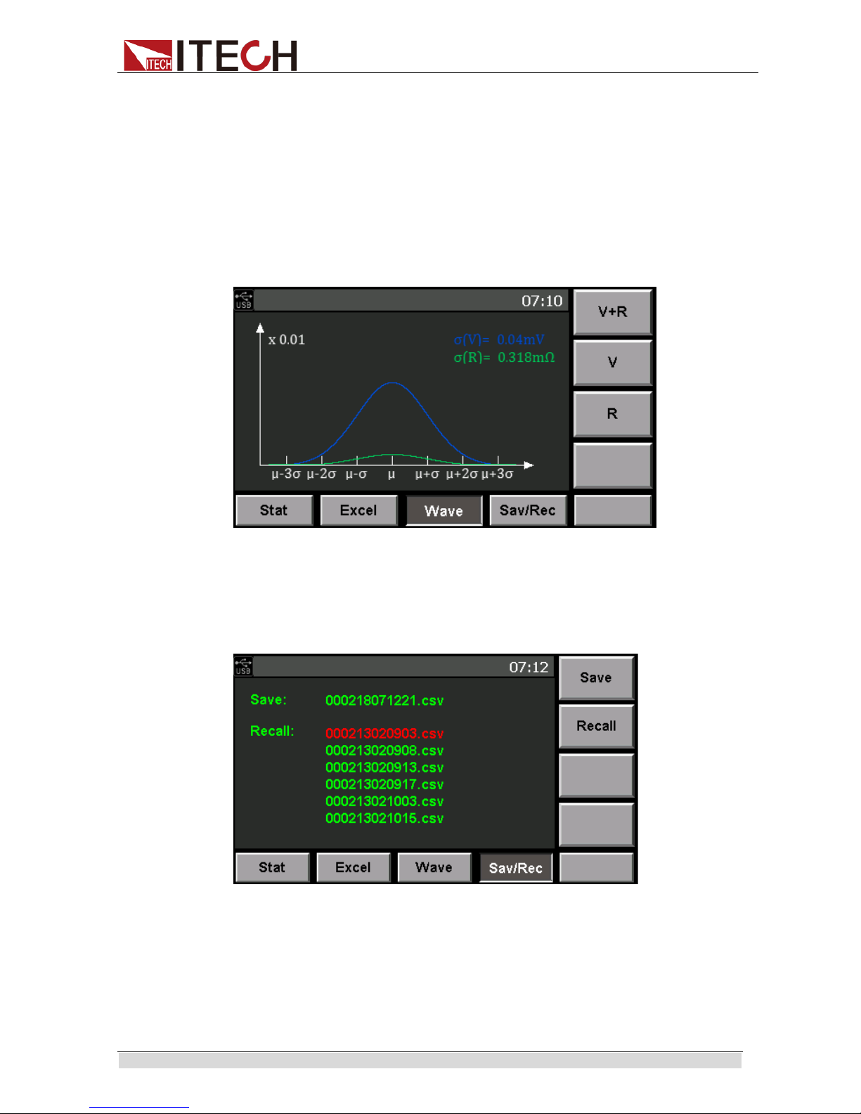
3.14.3Display Nor mal Distr i b uti on Plot
In Statistic Function page, select corresponding soft key of [Wave] to enter
Normal Di stribution Plot Display page to view normal distribution of voltage and
resistance. The user can increase or decrease wave display amplification
through the knob.
3.14.4Save/Recall Measurement Data
In Statistic Function page, select corresponding soft key of [Sav/Rec] to enter
Save inter f ace to save t he data t o USB or to ent er R ecal l i nter f ace to r ecall data
saved in USB. Before sa ving/recalling data, please insert USB.
Save Data
In Save/Recall page under Statistic Function, measurement data are saved in
USB in CSV format. The file is named after the current saving time. Press
corresponding soft key of [Save] to save Excel data to USB. CSV file contents
are as shown below.
Page 38

Function and Features
Copyr ight © Ite c h Electronics Co., Ltd. 30
Recall D ata
Insert USB with files to be recalled inside. The instrument will search for the
data file inside and display file list, as shown above. Press Down key to select
required fi le name and press [Recall] key to recall data records in the USB.
3.15 Zero-Adjust Function
Execute zero adjustment befor measuring to nullify any residual offset voltage
from the instrument or measurement environment. Measurement accuracy
specifications are applicable after zero adju stment.
Zero adjustment is a function which adjusts the zero point by deducting the
residual value obtained during 0Ω measurement. For this reason, zero
adjustment must be performed when connection is made to 0Ω. However,
connecting a sample with no resistance is difficult and therefore is not practical.
In this respect, when performing the actual zero adjustment, create a pseudo
connection to 0Ω and the adjust the zero point.
Wiring principle for Zero-Adjustment
The voltage between Sense(Red) and Sense(Black) becomes 0V according to
the Ohm’s Law of E=I*R. In other words, if you set the voltage between
Sense(Red) and Sense(Black) to 0V, this gives you the same state of 0Ω
connection.
Before executing zer o adjustment, connect the test leads ( probes) as follows:
1. Connect Sense (Red) to S ense (Black).
2. Connect Source (Red) to Source (Black).
3. Connect Snese(Bl ack) and Source(Black) .
Note
The detailed information for test leads probes, please refer to the test lines introduction.
Sine the amount of zero adjustment varies with the position and state of the
Page 39
Function and Features
Copyr ight © Ite c h Electronics Co., Ltd. 31
measurement leads (probes) (i.e., their length, shape, position, etc.), the
measurement leads must be positioned in the actual mea surement state befor e
performing zero adjustment.
Wiring Method for Zero-Adjustment
When execute zero adjustment, the four terminal short connection of test lines
provided by ITECH wi th the help of Zero adjustment board
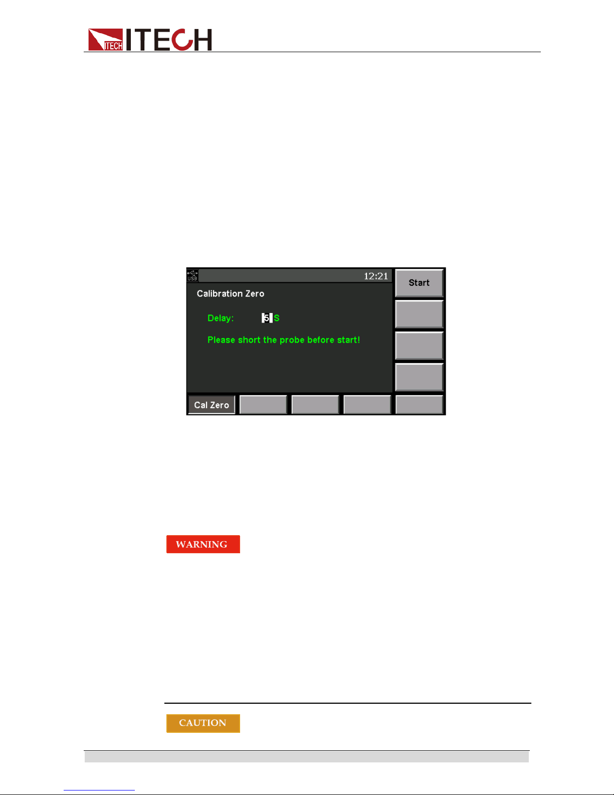
Executing Zero-Adjustment
1. Connecting the test line probes to zero adjustment board correctl y.
2. Press [Cal Zero] in front panel and enter the Calibration zero page.
3. In calibration zero page, user can set the delay time and delay execute the
zero adjustment, the delay time can set from 0 to 9 se ncond.
4. Press [Start] softkey and start zero adjust m ent.
3.16 External Control(EXT I/O)
The EXT I/O interface in IT5101 rear panel is used to external output terminals
and external control terminals. Please pay attention to this alarm information
before connecting
To avoid electric shock or damage to the instr ument, always observe the
following precautions when connecting to the EXT/ I/O terminals.
Always turn off the power to the instr ument and to any d evices to be
connected before making con nections.
During operation, a wire becoming dislocated and contacting another
conductive ob ject can be serio us hazard. Make sure that
connections are secure and us e screws to secur e t he external
connectors.
Ensure that devices and systems to be connect ed to the EXT I/O
terminals are properly isolat ed.
Page 40
Function and Features
Copyr ight © Ite c h Electronics Co., Ltd. 32
Do not apply voltage or current t o the EXT I/O terminals that exceeds t heir
ratings.
When driving relays, be sure to install diodes to absorb
counter-electromotive force.
Be carefull not to short-cir cuit ISO_5V to ISO_COM.
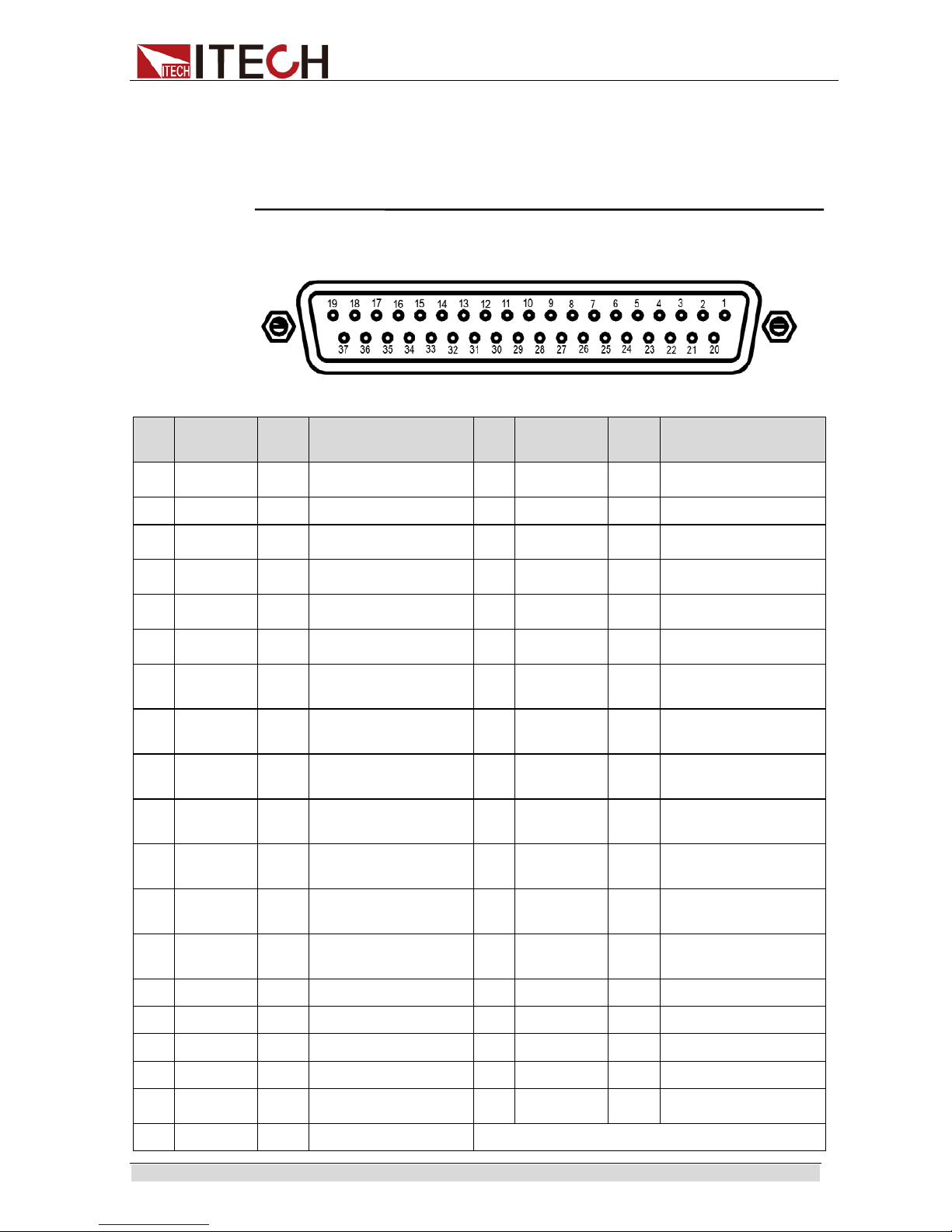
Pin definition
Pin Signal
name
I/O Function Pin Signal name I/O Function
1
TRIG
——————
IN External trigger 20
OADJ
___________
IN Zero adjustments
2 (Reserved) IN - 21 (Reserved) IN 3 (Reserved) IN - 22
LOAD0
____________
IN Load no. bit 0
4
LOAD1
____________
IN Load no. bit1 23
LOAD2
____________
IN Load no. bit 2
5
LOAD3
____________
IN Load no. bit 3 24
LOAD4
____________
IN Load no. bit 4
6
LOAD5
____________
IN Load no. bit 5 25
LOAD6
____________
IN Load no. bit 6
7
MANU
____________
IN
Comparator manual
control
26 (Reserved) IN -
8 ISO-5V - Isolated 5V power output 27 ISO-COM -
Isolated common signal
ground
9 ISO-COM - Isolated common signal
ground
28
EOM
________
OUT End of measurement
10
ERR
________
OUT Measurement fault 29
INDEX
___________
OUT
Analog measurement
finished
11
R_HI
________
OUT Hi
resistance judgment
result
30
R_IN
________
OUT IN
resistance judgment
result
12
R_LO
________
OUT Lo
resistance judgment
result
31
V_HI
________
OUT Hi
voltage judgement
result
13
V-IN
________
OUT IN
voltage judgement
result
32
V_LO
________
OUT Lo
voltage judgement
result
14 (Reserved) OUT - 33 (Reserved) OUT 15 (Reserved) OUT - 34 (Reserved) OUT 16 (Reserved) OUT - 35 (Reserved) OUT 17 (Reserved) OUT - 36 (Reserved) OUT 18
PASS
_________
OUT PASS judgement result 37
FAIL
_______
OUT Judgement result Fail
19 (Reserved) OUT - -
Page 41

Function and Features
Copyr ight © Ite c h Electronics Co., Ltd. 33
Signal Descriptions
The function descri ption of external control terminals as follows:
External trigger input(TRIG
——————
)
Select Panel No. to l oad(LOAD0
——————
~LOAD6
_________
)
Zero-adjust signal input(OADJ
________
)
Manual comparator judgment input(MANU
__________
)
External output terminal functions:
End-of-Conversion si gnal output(EOM
_____
)
Reference signal output (INDEX
________
)
Measurement Fault signal output(ERR
_______
)
Comparator decisi on si gnal output (R-Hi
________
、R-IN
_________
、R-Lo
_________
、V-Hi
_________
、V-IN
_________
、V-Lo
________
、
PASS
_________
、FAIL
_________
)
TRIG
——————
When the external trigger, one measurement is taken each time the TRIG
——————
signal tr ansitions from High to Low.
This tri gger signal is ignored when internal triggering is enabled.
Trigger functions are also available for statistical calculation, recording to
memory and output of measured val ues (valid also with internal triggering)
LOAD0
_______________
~ LOAD6
_________________
Select a Panel No. to load and apply a TRIG
——————
signal to load the select ed Panel
No. and measure. LOAD0
——————
is the LSB, and LOAD6
_________
is the MSB.
When a TRIG signal is applied, if LOAD0
——————
through LOAD6
_________
are unchanged
from the previous trigger event, panel settings are not loaded. In this case,
using external triggering, one measurement is taken as usual when the TRIG
——————
signal is applied.
Panel
No.
LOAD6
____________
LOAD5
____________
LOAD4
____________
LOAD3
____________
LOAD2
____________
LOAD1
____________
LOAD0
____________
*
0 0
0 0 0 0 0
1
0 0
0 0 0 0 1
2
0 0 0 0 0 1 0
3 0 0 0 0 0 1 1 4 0 0 0 0 1 0
0
5 0 0 0 0 1 0
1
……
125 1 1 1 1 1 0
1
Page 42

Function and Features
Copyr ight © Ite c h Electronics Co., Ltd. 34
126 1 1 1 1 1 1
0
* 1 1 1 1 1 1
1
0:( HIGH: Open of from 5v to 24V 1: (LOW: 0V~0.9V)
* When a TRIG
——————
signal is applied with LOAD0
___________
~ LOAD6
______________
set to all 1’s or all
0’s, no Panel Load occurs.
At least 70 ms is r equi r ed for t he setti ngs to chan ge aft er execut i ng a Panel
Load (the actual time depends on the particular function, range and
sampli ng rate).
When set to external trigger mode, one measurement is taken upon load
completion.
OADJ
______________
Zero adjustment executes once when the OADJ
___________
signal transitions from High
to Low.
MANU
_________________
When the MANU comparator mode is selected, comparator judgment is
enabled while the MANU
__________
signal is Low.
ERR
__________
Indicates a measur e ment fault.
The Synchronous ERR
_______
output setting causes ERR
_______
output to be synchronous
with EOM
_________
output, while with the Asynchronous ERR
_______
output setting causes
ERR
_______
output to follow actual (asynchronous) contact of the probes with the test
object.
INDEX
_________________
The INDEX
___________
signal is output during the Trigger W ai t , Del ay, Self-Cali brati on and
Calculation states.
This signal is not output while measuring the resistance of test objects. This
signal transitions from Hi(Off) to Lo (On) to indicate that the test object can be
removed.
EOM
____________
This signal indicates the end of a measurement (End-Of-Conversion)
This signal indicates when comparator judgment results and ERR
_______
output
(when SYNC is enabled) are available.
R-Hi
__________
、R-IN
___________
、R-Lo
__________
、 V-Hi
____________
、V-IN
___________
、V-Lo
___________
These are the results of comparator decision.
Page 43

Function and Features
Copyr ight © Ite c h Electronics Co., Ltd. 35
PASS
_____________
This signal indicates when both resistance and voltage judgment results are IN
(ΩV mode).
It transitions to Low (ON) when both the resistance and voltage judgment
results ar e IN.
In the Ω and V modes, this signal is the same as R-IN and V-IN outputs,
respectively.
FAIL
____________
This signal transitions to Low (ON) when PASS
_____________
is Hi (OFF).
Note
The Sense terminal and source terminal introduction for test line refer to test lines
description.
The EOM
________
and INDEX
__________
signals are ini tialized HIGH( O FF) at power on.
If it is not necessary to change the measurement condit ions, set LOAD0
___________
through LOAD6
______________
to either Hi or Lo.
To avoid erroneous comparator judgments, both the PASS
_____________
and FAIL
____________
signals should be checked.
3.17 ERR Output
The ERR output signal indicates the occurrence of measurement fault
conditions (such as open test leads, or a bad conta ct).
There are two ERR output methods.
Synchronized with EOM Output (Sync)
Measurement faults detected while measuring (not while awaiting trigger or
during delay or calculation intervals) , are indicated by ERR output synchro nous
with EOM output(the end-of-measurement signal).
ERR output LOW (On): A measurement fault has prevented correct
measurement.
ERR output HIGH (Off): Correct measurement obtained (OF or –OF:
Out-of-range cases are included)
Asynchron ous with EOM Output (ASync)
Measurement faults (test lead connection conditions) are output in real time.
The output is asynchronous wit h the TRIG
——————
signal and EOM output .
ERR Output Low (On): Measurement fault condition(open test leads, or a bad
contact)
ERR Output High (Off): Test lead connections are normal
Setting Method
1. Press [Menu] and enter m enu setti ng.
2. Press [Sys Config] and enter to system configur ation page.
3. Press Up/Down dicrection keys and select “Err Out”, set the ERR output
method.
Page 44

Function and Features
Copyr ight © Ite c h Electronics Co., Ltd. 36
ASync: Asynchronous with EOM Output
Sync: Synchronized with EOM Out put
4. Press [Enter] to confi rmed.
3.18 Setting EOM Signal
1. Press [Menu] and enter m enu setting.
2. Press [Sys Config] and enter to system configuration page.
3. Press Up/Down dicrection keys and select “EOM Mode”, set the EOM output
method.
When EOM Mode set to “ Pul se” out put m ode, it need to set pulse time. The uni t
is S. Otherwise, set to Hold mode, there i s not this item setting.
3.19 Timing Chart
ERR output (ASync)
Contact state
Contact
Open
ERR
________
(Async)
Page 45

Function and Features
Copyr ight © Ite c h Electronics Co., Ltd. 37
t1: ERR Output respond time ≤5ms
External Trigger Timing Chart
t1: Trigger pulse widt h, 0.5ms or more
t2: Delay Time, per setting
t3: Measurement time, the value is Different according to the current
sampli ng mo de, detailed information refer t o specification.
t4: Calculation time, 0.18ms, deviation is ±0.02ms
t5: HOLD setting: Holds until the next trigger is detected, PULSE setting:
Remains only for the specified pulse width
Auto Trigger Timing Chart
t1: Delay Time, per setting
t2: Measurement time, the value is Different according to the current
sampli ng mo de, detailed information refer t o specification.
t3: Calculation time, 0.18ms, deviation is ±0.02ms
t4: EOMoutput pulse width, HOLD setting: Holds until the next trigger is
detected, PULSE setting: Remains only for the specified pulse width
Comparator result
ERR
________
(sync)
Comparator result
ERR
________
(sync)
Page 46

Routine Maintenance
Copyr ight © Ite c h Electronics Co., Ltd. 38
Chapter4 Rout ine Maintenance
This chapter describes the general maintenance items and methods for IT5100
internal resistance tester.
4.1 Self-test
IT5101 has the self-test function. For self-test details, refer to Chapter 2.7
“Power-on Self-test”.
4.2 Routine Maintenance
This section introduces the basic maintenance involved in routine operation of
the instr ume nt, such as cleaning, self-repair, etc.
Cleaning
Wipe the machine with dry or slightly wet cloth. Do not wipe the inside of the
machine without permission. Cut off the internal resistance tester before
cleaning.
Reset
Factory sett ings of the system will be restored by implementing this operation:
1. Select [Menu] to enter the system menu.
2. Press the soft key corresponding to [Reset] to enter the system
initi ali zation interface, as shown below.
3. Press the [SetReset] or [SysReset] key and select the menu to be
initi ali zed. The detai led reset items please refer to 3.4 Reset S ystem.
4. Finished and return to Meter page.
4.3 Contact ITECH Engineer
This section introduce s the procedures for troubleshooting.
Page 47

Routine Maintenance
Copyr ight © Ite c h Electronics Co., Ltd. 39
Preparations before contact
In case of instrument failure, make the following preparations before returning
the instr ume nt to ITECH for repai r or contacting t he engineer.
1. Complete all inspections specified in “Self-check of Instrument Fault” and
check wheth er the faul t still occurs.
2. If the fault still occurs, carefully read the warranty service and restriction
requirements in the foreword of the manual and confirm that your
instrument meets the warranty service requirements.
3. To send the instrument back to the manufacturer for repair, see the
requirements in 4.4 “R eturn for Repair”.
Self-check of Instrument Fault
In case of instrument failure, please perform the following self-checks. If the
instrument can be recovered by simple check, the cost and time can be saved.
Before contacting t he engineer of ITECH, please check the following items.
Check whether the instrument is powered on.
Check whether the instrument is started up nor mally.
Check whether the fuse i s in good condition.
Check whether other connectors are in good condition, including cables,
plugs, etc.
Check whether the system configur ation is correct in operation.
Check whether the self-test is successfully and whether all specifications
and perform ance meet the specified requirements.
Check whether the instrument displays error information.
Use other instruments instead of this instrument for confirmation.
SN collection
ITECH will improve the product performance, availability and reliability from
time to time. The service personnel of ITECH will record the changes of each
instrument , and al l the r el evant information will be i dentified according to the SN.
The SN will be used as the tracking ID of the instrume nt returned for repai r.
To contact the engineer, the valid SN will be an effective guarantee for effective
service and complete information. You can obtain the instrument SN in the
following methods:
1. Press [Menu] to enter the system setting interface
2. The system will ent er i nt o “ Sys Info” by default. If the syst e m is displayed in
other menus, press [Sys Info] to enter the “System Information” interface
and view the product model, SN, software version, etc.
Page 48

Routine Maintenance
Copyr ight © Ite c h Electronics Co., Ltd. 40
3. Record the SN.
Calibration interval
The calibration frequency recommended by ITECH for IT5101 internal
resistance t ester i s once a year.
4.4 Return for Repair
Before returning the instrument for repair, please read the following
requirements.
Packaging
Refer to the f oll ow i ng steps to package the inst r ument t o be ret ur ned f or r epai r.
Pack the instrument to be repaired into the package used in delivery, including
relevant accessori es.
Provide the detailed problem description, such as copy of error information and
any related problem i nformation.
The instrument may be damaged if the unspecified package is used for
delivery. Use the special package for delivery, and pa ck the instrument
according to the packaging standards of delivery.
Do not use the styrene particle material of any shape as the package material,
as the instrument cannot be wel l f ixed in the package or prevented from
shaking. In addition, t he instrument m ay be dam aged by static electric ity
generated by styrene part icles or penetration of styrene particles into holes of
the rear panel.
Read the requirements of transportation costs of warranty services in the
foreword before delivery.
Page 49

Remote Control
Copyr ight © Ite c h Electronics Co., Ltd. 41
Chapter5 Rem ot e Cont r ol
Four standard inter faces are equipped for IT5101: GPIB, USB, LAN and RS232.
Users can choose any of the USB, GPIB, RS232 and LAN to achieve the
communi cation with PC.
5.1 USB Interface
Use a cable with two USB ports to connect internal resistance tester and
PC.You can program through USB interface to achieve all functions of internal
resistance t ester.
The functions of USB488 interface are as follows:
Interface is 488.2 USB488 interface
Receive the following request: REN_CONTROL, GO_TO_LOCAL, and
LOCAL_LOCKOUT
When the interface receives MsgID = TRIGGER USBTMC command,it
will tr ansmit the TRIGGER command to the function layer
The functions of internal resistance tester’s USB488 are as follows:
receive all SCPI commands
device is SR1 enabled
device is RL1 enabled
device is DT1 enabled
5.2 GPIB Interface
Use a IEEE488 bus to connect GPIB inter faces of i nternal r esistance tester and
PC.Please ensure that the screws have been screwed down in order to have a
full connect ion.Then press [Menu] to enter the system menu and press [Comm
Set] to set the GPIB address.The address range of internal resis tance tester is
0-99. After you set the address,please press[Enter] button to confirm. GPIB
address is saved in nonvolatile memory.
5.3 LAN Interface
Press[Menu] > [Comm Set] button to enter the system s et. Pl ease sel ect “LAN ”
in the Communication from System and then configure Gateway, IP, Mask and
SocketPor t in the LAN option.
Connect the LAN interface of internal resistance tester to the computer with a
reticl e (cr ossed). T he gatew ay ad dres s sh oul d be consistent with that of t he P C,
and the IP address should be at the same network segment with the PC’s IP
address.
Page 50
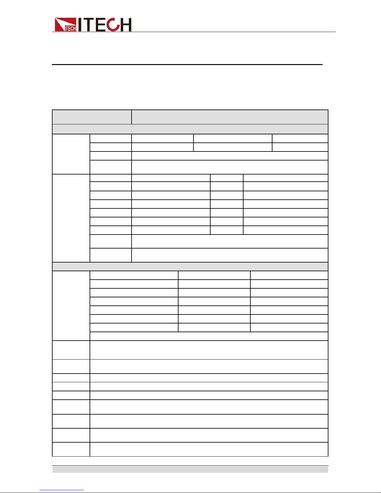
Specification
Copyr ight © Ite c h Electronics Co., Ltd. 42
Chapter6 Specification
This chapter will introduce the rated voltage, current, power and many other
main para meters of IT5101 series.
6.1 Main technical parameters
Model IT5101
Measurement Range
Voltage
Range -6V~+6V -60V~+60V -300~+300V
Resolution
10uV 0.1mV 1mV
Accuracy ±(0.01%+0.01%FS)
Temperature
Coefficient
±(0.001%+0.001%FS)/℃
Resistance
Range
3mΩ
Resolution
0.1 uΩ
Range
30mΩ
Resolution
1 uΩ
Range
300mΩ
Resolution
10uΩ
Range
3Ω
Resolution
0.1 mΩ
Range
30Ω
Resolution
1 mΩ
Range
300Ω
Resolution
10 mΩ
Range
3000Ω
Resolution
0.1Ω
Accuracy
±(0.4%+0.05%FS)
±(0.4%+0.1%FS) (3mΩ)
Temperature
Coefficient
±(0.04%+0.005%FS)/℃
±(0.04%+0.01%FS)/℃ (3mΩ)
Specifications
Sample Time
sample
R&V (ms)
R/V (ms)
EX.FAST(50Hz) 8 4
FAST(60Hz)
24
12
MEDIUM(50Hz)
80
40
MEDIUM(60Hz)
68
34
SLOW(50Hz)
200
100
SLOW(60Hz)
200
100
* Allowab le erro r is ±10 ms in “SLOW” status and ±2 ms in other modes.
Response
Time
10ms
(Response time is the value obtained when pure resistance is measured, and is only for reference. It
may be undulation due to different DUTs)
Input
Resistance
>=1MΩ
Input Rating
DC±300V
Channel
1ch
Interface
GPIB,USB,LAN
Open circuit
voltage
0.003Ω/0.03Ω/0.3Ω/3Ω/30Ω about 15V peak
300Ω/3000Ω about 4V peak
Fuse
specification
AC100V~ AC120V:1.6A T
AC220V~ AC240V:1.25A T
Working
temperature
0℃~40℃ Under 80%RH (non-condensation)
Storage
temperature
-10℃~50℃ Under 80%RH(non-condensation)
Page 51
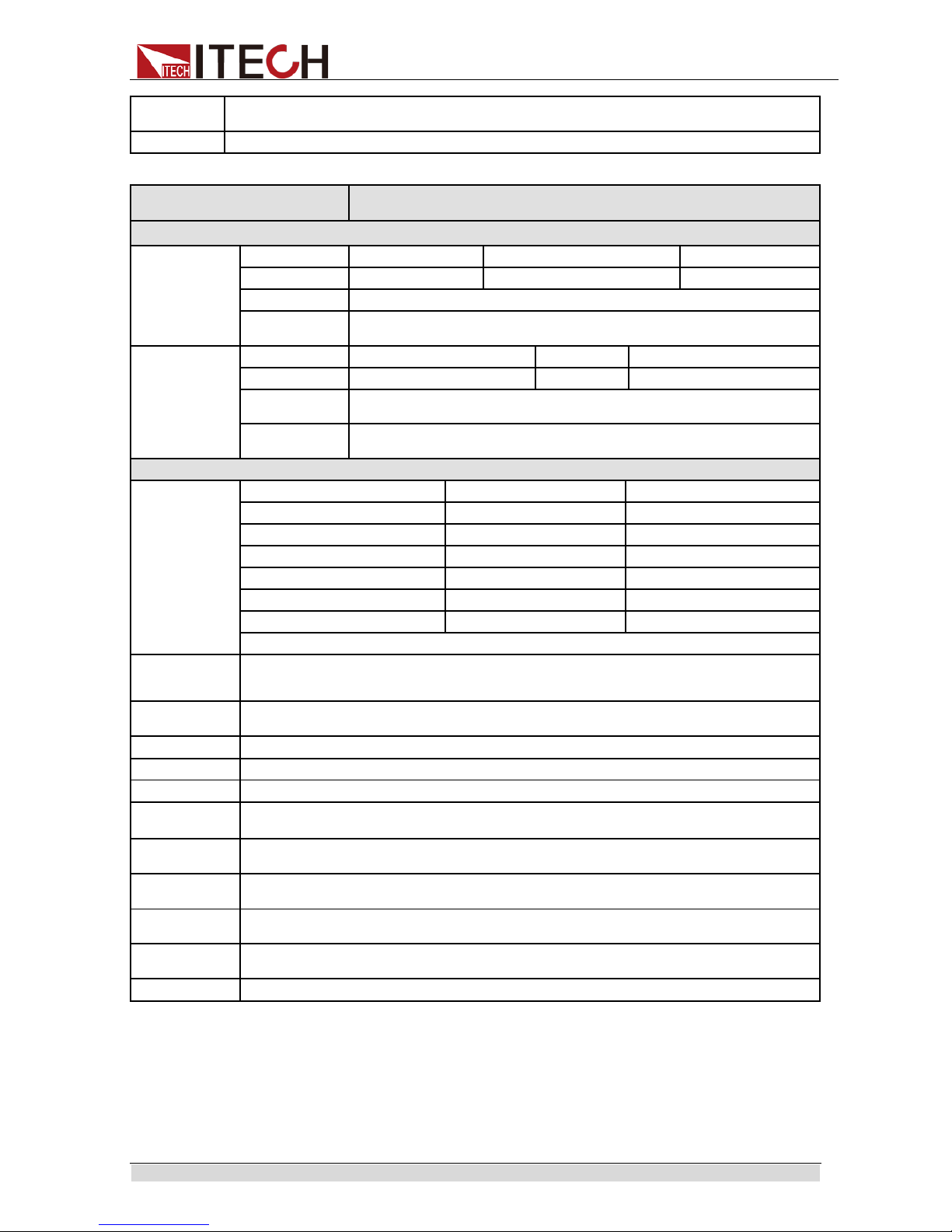
Specification
Copyr ight © Ite c h Electronics Co., Ltd. 43
Dimension
( mm)
384*230*105(mm)
Weight( net)
2.4KG
Model IT5101E
Measurement Range
Voltage
Range -6V~+6V -60V~+60V -300~+300V
Resolution
10uV 0.1mV 1mV
Accuracy ±(0.01%+0.01%FS)
Temperature
Coefficient
±(0.001%+0.001%FS)/℃
Resistance
Range
300mΩ
Resolution
10uΩ
Range
3Ω
Resolution
0.1 mΩ
Accuracy
±(0.4%+0.05%FS)
±(0.4%+0.1%FS) (3mΩ)
Temperature
Coefficient
±(0.04%+0.005%FS)/℃
±(0.04%+0.01%FS)/℃ (3mΩ)
Specifications
Sample Time
sample
R&V (ms)
R/V (ms)
EX.FAST(50Hz)
8
4
FAST(60Hz)
24
12
MEDIUM(50Hz)
80
40
MEDIUM(60Hz) 68 34
SLOW(50Hz) 200 100
SLOW(60Hz) 200 100
* Allowab le erro r is ±10 ms in “SLOW” status and ±2 ms in other modes.
Response
Time
10ms
(Response time is the value obtained when pure resistance is measured, and is only for reference.
It may be undulation due to different DUTs)
Input
Resistance
>=1MΩ
Input Rating
DC±300V
Channel
1ch
Interface
GPIB,USB,LAN
Open circuit
voltage
0.003Ω/0.03Ω/0.3Ω/3Ω/30Ω about 15V peak
300Ω/3000Ω about 4V peak
Fuse
specification
AC100V~ AC120V:1.6A T
AC220V~ AC240V:1.25A T
Working
temperature
0℃~40℃ Under 80%RH(non-condensation)
Storage
temperature
-10℃~50℃ Under 80%RH(non-condensation)
Dimension
( mm)
384*230*105(mm)
Weight( net)
2.4KG
The above specifications may be subject to change without prior notice.
When the current in the working cicui t which is connected to the battery changes
quickly may affact the m easurement acscuarcy!
1. In Med, add ±0.01%FS; in Fast, add ±0.02%FS; in Ex_fast, add ±0.03%FS.
2. In Med, add ±0.1%FS; in Fast, add ±0.2%FS; in Ex_fast, add ±0.5%FS (3mΩ range).
3. The a bov e da t a a re applicable for >5%FS working cond it ions.
Page 52

Specification
Copyr ight © Ite c h Electronics Co., Ltd. 44
6.2 Supplemental characteristics
Recommend ed calibr ation frequency:
once a year
Page 53

Contact US
Thank you for purchasing ITECH products. If you have any doubt about this product, please
contact us as follow.
1. Please refer to t he C D -ROM of related user’s manual in package.
2.
Visit ITE CH website www.itechate.com .
3. Select the most convenient contact for f urther consultation.
 Loading...