

Page 1

Rack Mount
LCD-Keyboard Drawer
1U Model Setup and Operating Guide
A Technical Guide for System Integrators
and Service Technicians
Page 2

The information contained in this document is believed to be
accurate. However, no responsibility is assumed for its use,
nor for any infringements of patents or other rights of third
parties which may result from its use. This information is
subject to change without any notice.
Page 3

CONTENTS
Introduction ........................................................... 1
Safety Guidelines .................................................. 2
Unpacking ............................................................. 4
External Views ...................................................... 5
Front View ........................................................................... 5
Side ViewOSD Controls ................................................... 6
Top ViewAudio Components ........................................... 7
Back ViewConnectors ..................................................... 8
System Requirements .......................................... 9
Rack Installation ................................................. 10
Mounting Procedure ......................................................... 10
OSD Controls ...................................................... 14
Using the OSD .................................................................. 15
OSD Menu System ........................................................... 16
Troubleshooting Techniques ............................... 18
Technical Specifications ..................................... 19
Page 4

Setup and Operating Guide
Page 5

1
Setup and Operating Guide
Introduction
Your Flat Panel Monitor-Keyboard Drawer is an integrated
monitor-keyboard assembly designed for use with rack-
mounted servers. It can be easily set up in a standard 19
equipment rack or cabinet. The monitor-keyboard is
mounted on slide rails. The retractable assembly occupies
only 1U space, and its fold-down design makes storage and
access a real convenience.
The monitor-keyboard consists of a 14 (or 15 depending
on the model you purchased) TFT active matrix LCD
monitor, LCD controller designed to automatically work with
any standard analog video signal from a computer, a
keyboard with built-in touchpad mouse, and power supply.
An optional waterproof, sealed membrane keyboard is also
available.
This guide provides step-by-step instructions for installation
and use of your monitor-keyboard drawer.
Page 6

Setup and Operating Guide
2
Safety Guidelines
Before you setup your monitor-keyboard drawer, it is
important to follow certain basic safety precautions to
prevent damage to the product and to ensure your own
personal safety.
Handling the Drawer Assembly
The monitor-keyboard drawer is constructed of heavy gauge
metal and can weight up to 30 lbs. To avoid injury during
installation watch for edges and corners on the assembly.
*
To prevent the drawer from accidentally sliding out and cause
bodily injury, the unit is shipped with a metal strap installed
across the front bezel. It is recommended that you do not
remove it until the unit is installed in the rack, or when the
unit is set down on a level work area.
Power Connections
The monitor is shipped with a power cord compatible with
the AC wall outlet in your region. Use the supplied power
cord.
Do not remove any of the covers over the power supply and
LCD controller. High voltages are present. Only qualified,
authorized electronics service personnel should access the
electronics components.
Page 7

3
Setup and Operating Guide
Care for the LCD
The monitor is an active matrix LCD. Liquid crystal displays
are made of glass which will break or crack if mishandled.
Ventilation
The ambient temperature within a densely filled rack cabinet
may exceed that of the room temperature. It is important
that nothing blocks the ventilation openings of the power
supply.
Page 8

Setup and Operating Guide
4
Unpacking
As you unpack your unit check the packing material to
ensure that you have found all of the proper cables and
accessories. Save all of the shipping material in case you
need it for transporting the unit in the future.
The monitor-keyboard comes completely assembled. You
should find these items in your package:
w 14 or 15 monitor-keyboard assembly.
w Combo cable for video, keyboard and mouse.
w Power cord.
w Keys for the key lock.
Page 9

5
Setup and Operating Guide
External Views
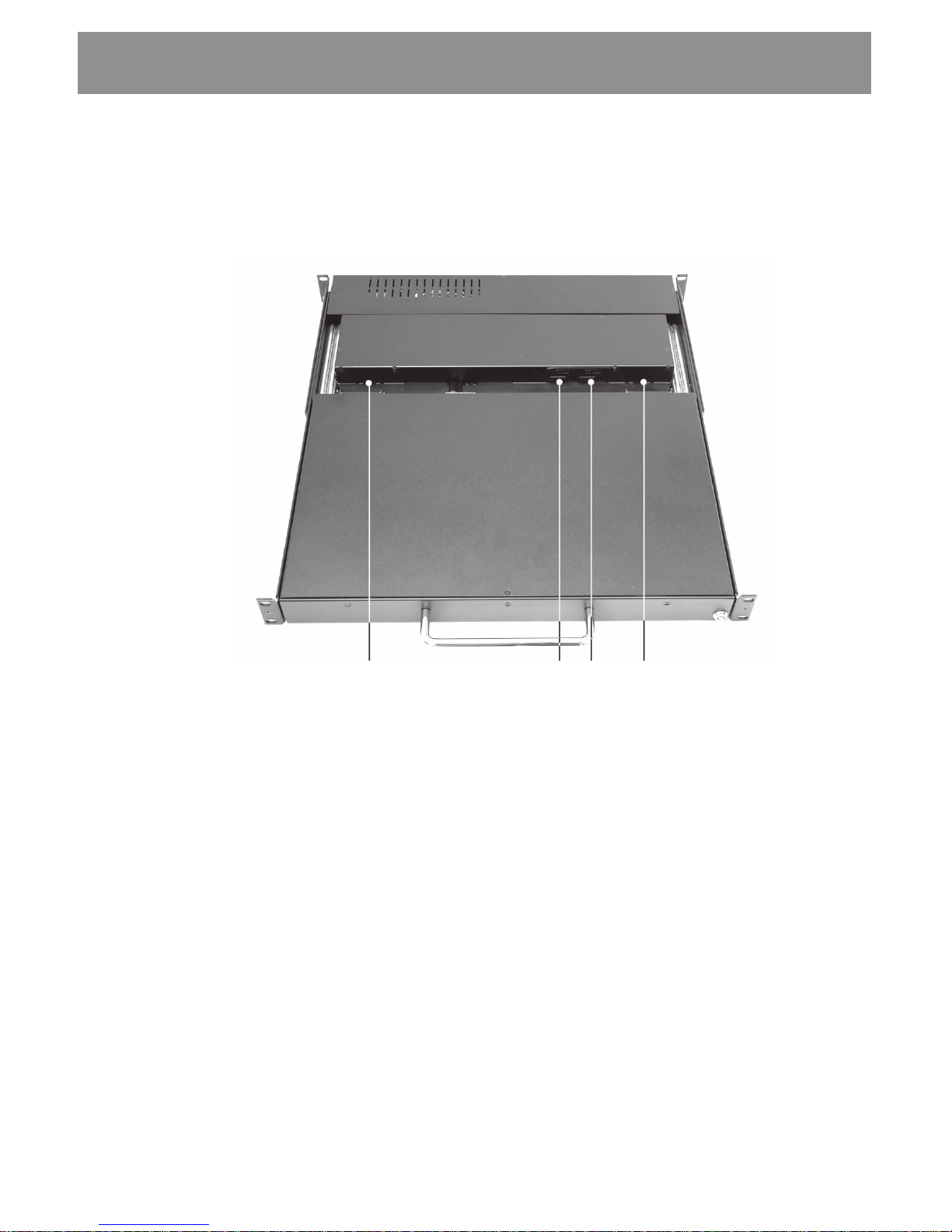
Front View
The monitor-keyboard drawer includes a flip-up LCD.
Unlock the flip-up LCD and use the handle to lift the LCD up.
Facing the unit youll find these components:
Slide rail
LCD
Touchpad
mouse
Keyboard
Rack mounting
bracket
Page 10

Setup and Operating Guide
6
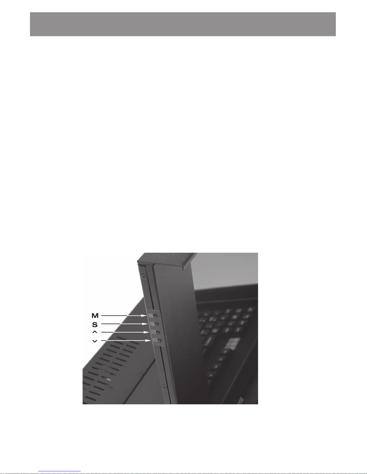
Side ViewOSD Controls
On the left side of the LCD youll find four push buttons. You
use them to adjust the display properties through an OSD
(On-Screen Display) menu system (see page 16 for a
description of the OSD).
Power supply
OSD controls
Page 11
7
Setup and Operating Guide
Top ViewAudio Components
Left speaker
Volume and
Tone controls
Right speaker
Page 12

Setup and Operating Guide
8
Back ViewConnectors
Audio input jack
Keyboard, video, mouse connectors
Power ON/OFF switch and AC
power connector
Page 13

9
Setup and Operating Guide
System Requirements
Your monitor-keyboard drawer connects to the video,
keyboard and mouse ports of a computer system. Your
computer system is required to have the following:
w A standard video card with an analog 15-pin video
output connector. You are also responsible to have the
video card and its driver already installed.
w PS/2 ports for both the keyboard and mouse.
w An audio-out jack if you will be using the audio compo-
nents of the unit.
Page 14

Setup and Operating Guide
10
Rack Installation
Mounting Procedure
The monitor-keyboard drawer is designed to be mounted in
a 19" equipment rack or cabinet. The unit has mounting
brackets that let you install it in racks ranging from 19 to 23
in depth.
Youll find the unit fully assembled on slide rails and func-
tional. Use the following steps to install the unit, connect the
cables and its ready to use.
Step 1. Determine the height that you want to install the
unit and locate it on the rack posts.
Step 2. Adjust the rear mounting bracket if necessary.
Loosen two screws to adjust the rear bracket
Page 15
11
Setup and Operating Guide
Step 3. Carefully insert the unit into the rack enclosure.
Align the front and rear mounting brackets with
the screw holes along the rack posts.
Step 4. Install the mounting screws. Tighten down all of
the mounting bolts.
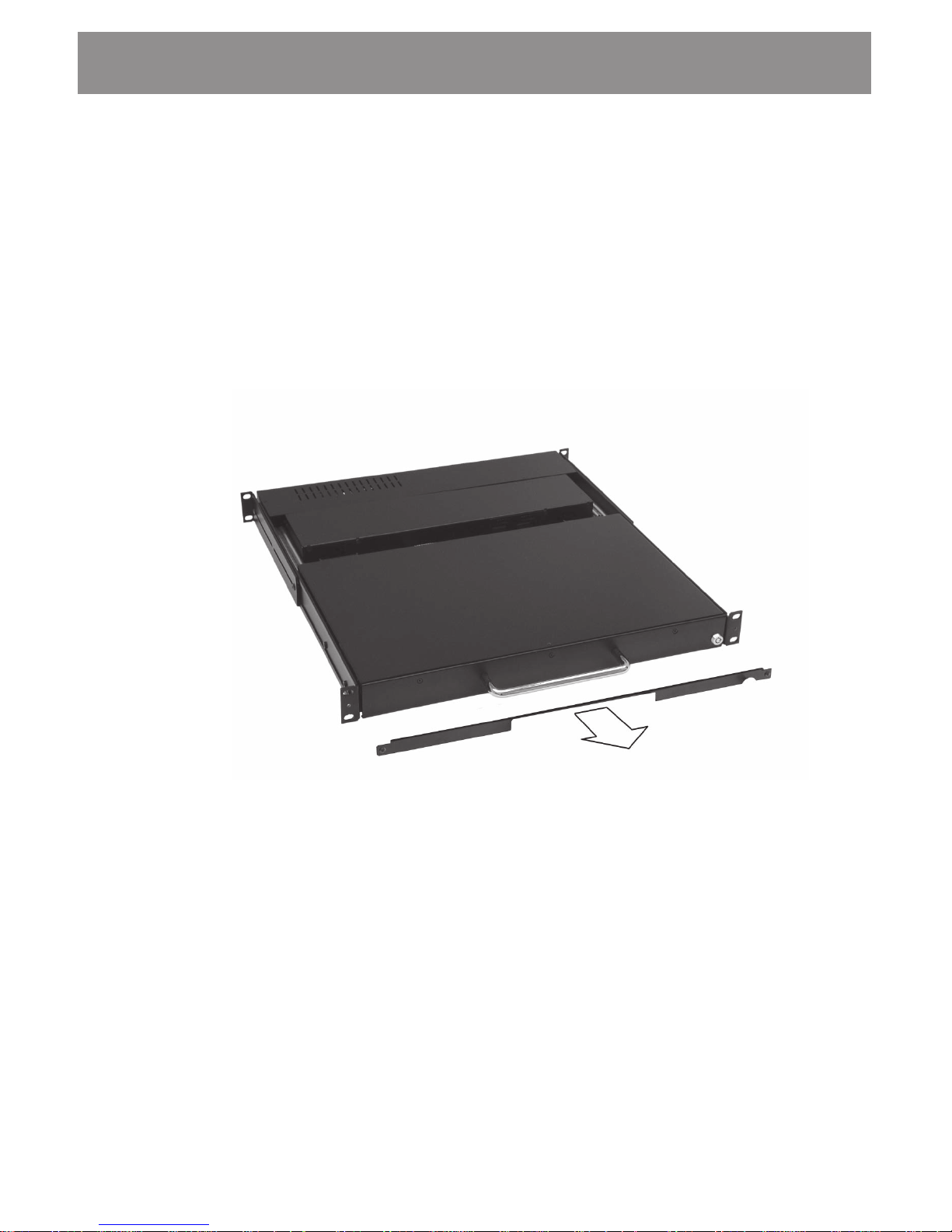
Step 5. Once the unit has been installed and secured,
remove the metal strap.
Removing the metal strap used to prevent the drawer from sliding out
during transportation and installation.
Page 16

Setup and Operating Guide
12
Step 6. Turn OFF your computer and then make all of the
cable connections. The keyboard and mouse port
connectors are color coded purple colored
connector for the keyboard and green colored
connector for the mouse.
Page 17

13
Setup and Operating Guide
Step 7. Unlock the flip-up LCD.
Step 8. Power up your system and turn on the unit by
pressing the AC power switch on the back of the
unit to the ON position. Grasp the handle and pull
the drawer forward. This will disengage the
momentary on/off switch and the unit should
power on.
Turn the key counter-clowise to unlock the
retractable drawer.
ON/OFF switch
Page 18
Setup and Operating Guide
14
OSD Controls
The LCD is driven by a conversion board that converts the
analog video signal into a digital video format that is ac-
cepted by the LCD monitors driver circuit. The conversion
board includes an integrated RAM-based OSD (On-Screen
Display) menu. The OSD uses four push buttons to let you
access menu system and make adjustments to the display
for optimum performance.
The front panel push buttons are arranged and labeled as
follows:
w Pressing M toggles the OSD on or off.
w Pressing S steps through the menu items.
w Pressing ~ or increases or decreases the selected
menu items numerical value.
Page 19

15
Setup and Operating Guide
Using the OSD
Follow these steps to activate the on-screen display:
Step 1. Power up the computer system and then turn on
the LCD.
Step 2. Press M to invoke the on-screen menu.
Step 3. Press S to step through the main options.
Step 4. Press either ~ or button to bring up sub-menus
of the highlighted option.
Step 5. Press M to step through the sub-menu options.
Step 6. Press either ~ or to modify the selected
parameter value. Pressing a button once in-
creases or decreases the numerical value by a
single digit. Holding down a button increases the
rate of change. Press M to return to the previous
screen.
Step 7. Af ter youve made your adjustments press M
repeatedly until the OSD is turned off.
Page 20

Setup and Operating Guide
16
OSD Menu System
The OSD menu system consists of a main menu and four
sub menus. The following is a brief description of each of
the menu items:
1. RGB MENU
BRIGHTNESS: Adjusts the black level of the Red, Green
and Blue channels.
COLOR TEMP: The settings are available to set white
point reference.
SHARPNESS: Adjusts image sharpness.
2. GEOMETRY MENU
AUTO-ADJUSTMENT: Performs automatic adjustment
of the vertical and horizontal image positions within the
display area of the LCD.
RGB Menu
Geometry Menu
Contrast Menu
Language Menu
NVRAM Menu
Reset
Save
S 1024 x 768
70.3 / 56.6
Brightness
Red
Green
Blue
Color Tem
p
Sharpness
Auto-Adjustment
H. Position
V. Position
H. Total
Auto Phase
Dela
y
Auto-Balance
Contrast
Red
Green
Blue
Balance
English
Spanish
Page 21

17
Setup and Operating Guide
H.POSITION: Adjusts the horizontal image position
within the display area of the LCD.
V.POSITION: Adjusts the vertical image position within
the display area of the LCD.
AUTO PHASE: Performs automatic adjustment of the
ADC sample pixel clock.
DELAY: Manual adjustment of the sample pixel clock
phase.
3. CONTRAST MENU
AUTO-BALANCE: Performs automatic adjustment of
color brightness in relation to the background.
CONTRAST: Manual adjustment of individual RGB
channel contrast.
4. LANGUAGE MENU
Selects English or Spanish language OSD.
5. RESET
Reloads all parameters to factory settings.
6. SAVE
Saves current parameters.
O
When switching display modes the screen position may become
offset by a few pixels to the top/bottom or left/right in the
display area. This can be corrected by pressing “MENU” >
“GEOMETRY MENU” > “AUTO PHASE” > and then press “MENU”
> “SAVE”. Next time you switch to this mode the correct screen
position will be recalled.
Page 22

Setup and Operating Guide
18
Troubleshooting Techniques
LCD screen shows garbage or bad characters or
vertical/horizontal color lines or bar:
ü Detach the video connection to the LCD screen and
attach to a good external CRT type monitor.
If the
external CRT monitor shows normal video then it could
be compatibility issue. Replace the VGA card and use a
different VGA card and try it again with the LCD screen.
If it still failed then it could be a bad conversion board or
loose cable inside the LCD subassembly.
ü If the external CRT monitor shows similar garbage
character then it is a bad video card.
LCD SCREEN works fine in Windows but acted
funny when running certain programs or games:
ü The built-in Intelligent Analog-Digital conversion board
(AD board) should adjust the screen to the proper
resolution to fill the entire display. However, certain
programs or display modes might cause the AD board
to not align or sync properly. Check if the program that
you are running is running under supported resolution.
You can also try adjusting the OSD to manually adjust
the resolution ( see Section 6 on Using The Systems
Controls ).
When switching display modes the screen position
becomes offset by a few pixels to the top/bottom or
left/right in the display area
ü This can be corrected by pressing MENU > GEOM-
ETRY MENU > AUTO PHASE > and then press
MENU > SAVE. Next time you switch to this mode
the correct screen position will be recalled.
Page 23

19
Setup and Operating Guide
Technical Specifications
Model 14/15
Enclosure 1U
LCD Type Active Matrix
LCD Color 262K / 16M
LCD Size 14.1 / 15.1
Resolution 1024x768
Brightness 100/250 cd/m
Response 40ms / 25ms
Contrast 150:1 / 300:1
Environment
Operating Temp. 0 to 40
o
C
Storage Temp. -20 to 60
o
C
Relative Humidity 10%-90% non-condensing
LCD MTBF 50,000 hours
 Loading...