

Page 1

OSD SERIES
DIRECT GAS-FIRED AIR HEATER
INSTALLATION, OPERATION AND MAINTENANCE MANUAL
FOR USE ONLY IN PAINT SPRAY BOOTHS AND DRYING OVEN APPLICATIONS
READ MANUAL CAREFULY BEFORE INSTALLING
OR OPERATING THE FURNACE
FOR YOUR SAFETY FOR YOUR SAFETY
If you smell gas follow these instructions, The use and storage of gasoline or other flammable
1) Open windows. vapors and liquids in open containers in the
2) Do not touch electrical switches. vicinity of this appliance is hazardous.
3) Extinguish any open flame.
4) Call the gas supplier immediately.
MODEL: SERIAL NUMBER:
JOB: DATE OF INSTALLATION:
WARNING
IMPROPER INSTALLATION, ADJUSTMENT, SERVICE OR MAINTENANCE CAN
CAUSE PROPERTY DAMAGE, INJURY OR DEATH. PLEASE READ THE
INSTALLATION, OPERATING AND MAINTENANCE INSTRUCTION
THOROUGHLY.
*THIS UNIT IS TO BE SERVICED BY QUALIFIED PERSONNEL*
**DO NOT TAMPER WITH THE UNIT OR CONTROLS**
INSTALLER’S RESPONSIBILITY
Installer please note: This equipment has been test fired and inspected. It has been shipped free from defects from
our factory. However, during shipment and installation, problems such as loose wires, leaks or loose fasteners may
occur. It is the installer’s responsibility to inspect and correct any problems that may be found.
THIS EQUIPMENT SHALL BE INSTALLED AND WIRED IN ACCORDANCE WITH THE REGULATIONS OF
THE NATIONAL BOARD OF FIRE UNDERWRITERS, CANADIAN ELECTRIC CODE AND LOCAL
GOVERNING BODIES. THE INSTALLAION CODE FOR “GAS BURNING, APPLIANCES AND
EQUIPMENT, CAN 1-B149”, AND APPLICALBLE PROVINCIAL REGULATIONS FOR THE CLASS, WHICH
SHOULD BE FOLLOWED CAREFULLY IN ALL CASES.
INSTALLER/SERVICE CONTRACTOR
NAME:
ADDRESS:
TELEPHONE:
CONTACT:
Page 2

GENERAL INFORMATION
GENERAL NOTES
This Direct Fired OSD Spray/Bake Unit, dual air dual temperature unit is designed to provide make up air to satisfy the
exhaust requirement of the paint spray booth. 100% volume on the spray cycle and 50% volume on the dry cycle. Normal
discharge temperature on spray cycle is between 70° F and 80° F. Normal discharge temperature on dry cycle is between
120° F and 180° F. The sequence of operation and wiring diagram are located in the weather housing on out door units and
burner compartments of indoor unit.
WARNING
Fire or Explosion hazard can cause property damage, severe injury or death. Ensure that all air taken into the unit is
free from the presence of:
a) Flammable solids, liquids and gases.
b) Explosive materials. Example: grain dust, coal dust, gun powder etc.
c) Substance which may be come toxic when exposed to heat or passing through a gas flame.
INSTALLATION AND SERVICE INSTRUCTIONS
The information provided is a guide to the proper installation, operation and troubleshooting of the unit. Retain the manual
as a reference for operation and maintenance personnel. Should contact with the factory be necessary, provide the unit model
number and serial number. Install and wire the equipment in accordance with the applicable national and local governing
bodies codes. Authorities having jurisdiction should be consulted before making the installation. Local codes may require
additional safety controls and/or interlocks.
UNIT LOCATION
Prior to locating the unit check with the authorities having jurisdiction. The unit should be located with clearance to open
access doors and remove filters. Ensure that the unit is installed level. Provide adequate clearance on either side of the unit
to service blower, bearings, motors, drives and filters. Ensure that the position of the heater relative to support beams is
correct so as to provide adequate support for the equipment. For roof mounted units, check the spacing of the roof structure
beams to avoid interference with air ducts.
LOCATION OF ACCESSORIES
The remote panel will be shipped as a separate package. Mount the panel and have an electrical contractor install wiring.
FACTORY TESTING & START UP CHECKLIST
All OSD series units are factory fired and tested prior to shipping. Each unit is shipped with the tester’s report and a start-up
checklist. Complete the start-up checklist and return one copy to the factory.
1
Page 3

INSPECTION OF EQUIPMENT
All shipments are made F.O.B. the factory. The unit is securely strapped or blocked to prevent shipping damage and each
shipment inspected prior to leaving the plant. All parts, where feasible, are strapped to or included in the unit. Upon receipt
of goods, check the shipment against the bill of lading to ensure all items have been received. Carefully check the unit for
physical damage in the presence of the carrier’s representative. Should parts be missing or damage noted, file a claim
immediately with the carrier. ICE does not assume responsibility for the handling of the goods in transit and is not
responsible for the initiation of freight claims.
INSTALLATION AND SERVICE INSTRUCTIONS
Direct Gas Fired Air Heaters
LOCATION OF UNIT AND DISTRIBUTION
Inlet
The intake shall be designed and located to prevent snow, rain, flammable gas, toxic gases and other deleterious materials
from entering the unit. (Less than 500 F.P.M. is an accepted velocity.)
INSTALLATION
Smaller models are shipped as one total unit. All other models are shipped in sections that are easily erected on the job site.
The main sections consist of a burner damper section that contains the motor, and a blower section. The secondary sections
are the filter, louver, mixing box etc., which are added in sections as required.
1. All sections are pre-drilled and are bolted together in the field (as per Figure 1).
2. Belts must be installed on the motor, and limit and discharge controls may have to be mounted and/or wired.
3. When clearance is not a factor, ensure that the unit is adequately protected from obstruction.
NOTE: On roof top units the joints will have to be caulked to prevent rain from entering the unit.
Indoor Suspension
On indoor models holes at the base of the units are provided for 5/8” suspension rods (see Figure 6). Unit must be lifted and
handled from the lifting holes provided at each end of the channel iron, when suspending from the ceiling. If units are to be
lifted from the bottom for mounting on a platform (as with a forklift), unit must be supported.
NOTE: DO NOT LIFT CABINET WITHOUT THIS SUPPORT.
Rooftop Installation
Support rails (minimum of 4” high) must be provided underneath the unit. In some cases, more height may be required when
installing the supply duct through the roof (see Figure 1) or if a unit is a bottom discharge (see Figure 2).
Minimum clearance from the unit, to combustible construction, is clearly marked on the rating plate attached to the unit.
No source of flammable vapors, gases or dust shall be with in 20’ horizontally of any unit unless that source is separated from
the unit by an enclosure of fire and vapor resistive materials.
On indoor suspended units, when necessary to provide working clearance beneath the unit, the installation shall be made at a
suitable height above the floor.
2
Page 4

CONNECT DUCTWORK
1. On indoor units, install fresh air duct to inlet of unit. Install intake hood or louvers with screen.
a) Make required opening in wall and line with angle frame inside. Should be completed before outside is started to
avoid crumbling.
b) Insert insulated fresh air “collar” through opening with flanges turned out to provide rigidity.
c) Anchor intake hood with birdscreen to wall.
d) Caulk perimeter of opening to make rain tight.
2. Connect discharge air duct or discharge grille to unit outlet. If unit is installed on a roof, be sure that the duct going
through the roof is adequately flashed and sealed to prevent leakage (see Figure 1).
3. Where a ductwork system or other enclosure is directly connected to the inlet or outlet of the heater is such a way as to
cause a possible gas trap and accumulation of a flammable mixture, a pre-purge cycle shall be incorporated to provide not
less than 4 complete air changes of the ductwork or enclosure by volume prior to an ignition.
4. Where additional automatically operated inlet or discharge air louvers are used, they shall be electric interlocked to
ensure the maximum designed opening before either starting or running circuits may be energized.
EXHAUST INTERLOCK
a) This unit shall be electrically interlocked so that it will operate only when the associated exhaust system(s) is
functioning. An exhaust airflow proving switch shall be used (Refer to sheet exhaust interlock). For typical
application, and (wiring diagram) for electric hookup.
b) The total air discharge capacity of the unit must not exceed by more than 10% the total discharge capacity of
the exhaust systems in conjunction with which it is used. Where the tempered air is discharged directly into a
booth, the total air discharge capacity of the booth.
c) The exhaust air proving switches should be set as to open when the volume of exhaust drops by more than
10% (dirty exhaust filters, etc.).
CONNECT GAS SUPPLY
a) Run correctly sized gas line to the unit. Install manual shut off valve plug-cock type approved for the application.
NOTE: Gas line pressure must be a least 7” W.C” when unit is operating at full input (Burner manifold pressure at full input
is from 4” to 4 ½” W.C.) Check rating plate on unit for maximum gas input.
b) Bleed and vent lines shall be installed in accordance with the applicable requirements.
COMPLETE WIRING
1. Install remote supervisor panel or if summer-off-winter switch (is used) in the desired location.
2. Complete wiring to supervisor panel or summer-off-winter switch as shown on wiring diagram.
3. Install fused disconnect switch (to be furnished by installer) and connect 3 phase power supply to disconnect
switch mounted on unit. Voltage must correspond to voltage marked on rating plate.
4. Complete all wiring to accessories (interlocks) as per wiring diagram provided on the unit.
NOTE: It is recommended that filters be removed during winter operation, if up stream from burner.
3
Page 5

WARNING
FIRE OR EXPLOSION HAZARD CAN CAUSE PROPERTY DAMAGE, SEVERE INJURY, OR
DEATH.
Check for gas leaks with rich soap and water solution any time work is done on a gas control.
START-UP PROCEDURE
1. Remove shipping blocks from:
a) Blower if rubber or spring isolated.
b) Check to be sure that damper opens, if tied down, remove wire.
c) Check modulating discharge controller, on units, to ensure that it is in the blower air stream. On some units this
control may be mounted external from the unit. If so, check to see that the sensor installed is the discharge air stream
of the heater air and that the controller is wired to the modulating motor, regulating gas supply to burner.
2. Make sure that the main firing valve is closed, but that gas is available in the service line.
3. Check to ensure exhaust fans are wired into the control panel and that there is power to the exhaust starter relays.
Check to ensure exhaust fans interlock switches are installed and wired to the control panel.
4. Familiarize yourself with the sequence of operation and wiring diagrams this will give you information as to how the
unit operates in the paint and cure modes.
5. Check voltage to ensure it matches the voltage stamped on the unit rating plate, and all wires are connected between
unit and remote panel.
6. The timers TD-1 - TD-5 are factory set but you should check them to ensure they have not moved during transit to job
site.
a) Normal setting of high limits are paint mode -165°F cure mode -200°F auto reset.
7. Operate unit through paint mode by pushing in the system “on” push button. The unit should operate as per sequence
of operation.
a) Pilot
The Protector relay monitors the pilot flame through the flame rod. A minute current is sent from the relay through
the flame rod, and trough the pilot flame to “ground”. The relay detects the current flow and acts to open the safety
valve as required. When no flame exists, current cannot flow and the relay acts to close the valve. Current flow
depends only on flame contact on the rod: temperature of the rod is of no importance.
Since the flame rod is a current-carrying conductor, it must be free of any contact with conductive parts of the pilot
burner. Insulator must be clean, dry and free from cracks. While the flame rod is made of a heat resistant alloy it
may, after long service, deteriorate to the point of flame contact. Check for serious corrosion or loss of metal. It must
be tight enough in the insulator to maintain its position. Do not use too much force or the insulator may crack.
Proper operation of the flame rod can be checked by measuring the flame rod current; refer to flame safeguard
instruction sheet with unit. Lacking a micrometer, a check can be made with an operating burner through all its
normal phases. Relay response should be prompt with no chattering or drop out.
The spark rod (Midco Burner see Figure 5 for gap setting, Maxon Burner spark ignitor No. 18075) produces a high
tension arc at the correct location for lighting the pilot. Ignition transformer must be rated for 6000 Volts, 20
Milliampers secondary, minimum.
The spark rod or spark ignitor, must be free of contact with conductive parts of the pilot burner. Insulator must be
clean, dry and free of cracks. Check the spark rod for serious corrosion or loss of metal. It must be held tightly
enough is the insulator to maintain its position.
4
Page 6

Gap must be 1/16” to 3/32” (see Figure 5). Setting can also be checked by cycling the pilot. Ignition must be prompt
and positive. Do not allow careless positioning to cause arc of flame rod; serious relay damage would result.
The spark ignitor on Maxon burners, if ignitor shows deterioration of ignitor points the complete spark ignitor should
be replaced part No. 18075.
8. If pilot tries for ignition, but locks out, the air proving switches (high and low) that are mounted across the profile
plate, should be checked to make sure that the proper amount of air is flowing through the unit. Check to make sure
blowers are running in the proper direction. This can be checked by placing a differential gauge across the profile
plate of the burner section. If the pressure drop is between .30” W.C., and .95” W.C., these switches should be made,
then check pilot to ensure proper flame. Check instruction sheet for flame safeguard system.
Pilot adjustment screw is in the Thermax shut-off valve. When setting, adjust for the best reading, then open pilot set
screw slightly.
a) Main flame supervision: With units that have more than three feet of burner from point or supervision, a second
flame rod will be on the main burner. This switching is done with a time delay relay. See wiring diagram. This can
be disconnected for testing for pilot, or you have to ensure main flame by opening up the firing valve within 15
seconds after pilot solenoid is powered. As supervision will switch from pilot to main flame in that time. Check to
ensure that unit will lockout in the event of main flame failure on low-fire by closing main firing valve.
9. Gradually open firing valve to start main flame. Check for flame over entire burner length. Adjust the pressure
regulator to 4” or 4 ½ ” W.C. pressure or the amount of gas marked on the rating plate.
10. All OSD units may have Maxitrol modulation. Read over the Maxitrol literature for the high fire and low fire setting.
By removing the wire from #2 on the amplifier the unit will stay on low fire and allow you to set the by pass or low
fire setting to ensure that the flame is completely across burner and is between 1” and 1½ ” long (see literature
supplied with unit).
11. To set up high fire you will require spray test resistor 1.10K, dry (cure) test resistor 1.21K. These are attached to the
Maxitrol literature. These resistors should be placed across #3 and #4 of the amplifier on the unit (remove when test
is complete).
a) Check gas pressure switch setting.
High pressure gas switch …………………………………..…… 6” W.C.
Low pressure gas switch ………………………………….……. 2” W.C.
NOTE: The high and low gas pressure switches may be the manual reset type on some units.
FLAME SUPERVISION CHECK
a) The flame supervision should be checked periodically to insure that the controls are operational. With the unit
on full operation and firing, close the main manual firing valve and pilot manual firing valve. This should lock
out the unit.
b) The units with more than 3 feet of burner from the point of supervision have dual flame rod and a delay timer for
main flame supervision. Closing the main firing valve should lock out the safety relay and the unit should
shutdown.
c) The main safety valve should be checked for gas tightness by placing a manometer in the manifold between the
safety valve and the manual firing valve (a 1/8” plug is provided for this). If there is a build up of pressure with
the unit locked out and the manual valve closed, the safety valve should be replaced.
d) The complete gas line and manifold should be checked for gas tightness.
5
Page 7

C.F.M.
a) This unit depends upon an adequate supply of air for good combustion and operation. Care should be taken to
ensure that properly sized inlet hood and ductwork are installed and that the unit is discharging the right
amount of CFM.
TROUBLE SHOOTING GUIDE
On start up, the unit will not operate properly. It may be an electrical mix up in the wire from the unit to the control
panel (see wiring drawing).
The wire connector shown 12 are in the remote panel.
The wire connector shown E12 are on the unit.
It is recommended you have a volt meter AC/DC, and a differential pressure gauge 0” - 2”
(magnehelic) and a gas pressure gauge 0” - 12”.
SPRAY MODE
1. If inlet damper fails to open when system switch is pushed in.
a) Check to see if power is on #4. If no power supply starter overloads (1 OLS-1), may be open R1-1
normally closed contacts may be open. Main flame safe guard relay needs to be reset.
2. Fresh air damper open, but no power on #9.
a) Damper end switch open (DMES-1) reset.
3. High exhaust fan operating, no power on #13.
a) Check high exhaust fan inter lock switch.
4. If supply fan is not operating, check delay start timer (TD1) normally set at 3 seconds to allow for exhaust fan
to come up to speed to keep the booth from over pressure and blow the doors open.
a) Balance exhaust and supply fan.
5. No power on #40.
a) Check summer/winter switch.
b) Spray high limit (HL-S).
c) Check air flow across burner with a magnehelic gauge to ensure proper air flow. Should be a difference
between .45” and .65” W.C.
6. Power on #40, but burner will not come on.
a) Change flame safe guard relay.
7. Power on #40 burner tries to fire up but locks out.
a) Check pilot solenoid valve.
b) Check ignition transformer.
c) Check flame rod, if dirty clean, if cracked isolator replace.
6
Page 8

8.
Burner on low fire only.
a) Check TD2 timer low fire timer should be set at 20 seconds.
b) Check DC volts on #55 and #57, if above 5 V.D.C. modulation valve may be defective, replace.
9. See Maxitrol literature to trouble shoot the system.
NOTE: On custom built units the number designation may change.
Carefully check wire diagram supplied with unit.
BAKE MODE
1. Purge light “off”, dry cycle light not “on”.
a) Check and replace.
2. Burner not on, no power on #40.
a) Check dry high limit (HL-B).
b) Check low exhaust inter lock.
c) Check high and low profile air switches.
d) Check profile damper should be closed below burner.
3. Power on #40 burner not on. See instruction spray mode 5, 6, 7, and 8.
4. Burner on, but will not operate up to selector set point.
a) Check to see if temperature delay timer TD4 is powered and switch over from #12 to #11, on the
Maxitrol, amplifier is completed.
b) Check discharge sensor.
c) Refer to Maxitrol trouble shooting guide provided with this manual.
OPERATING PRINCIPLES OF THE RAW GAS BURNER
The raw gas burner is designed to operate in a duct of flowing fresh air. Fuel gas is fed directly to the burners; kinetic
energy of the air stream furnishes combustion air. The burner must be installed to fire with, and parallel to, the air
flow. By virtue of velocity impact and suction generated by the diverging shape of the combustion baffles, air is
induced into the air ports in the combustion zone. The air supply is constant though only that which mixes with the gas
flowing from the burner ports, takes part in combustion.
When a very small quantity of gas is admitted to the burner, sufficient mixing takes place in the low fire slot within the
burner, casting and combustion takes place in this zone. Since the low fire zone is contained within the burner casting
it is effectively shielded from fire disrupting uncontrolled air entry.
As the gas is increased the flame progresses into the intermediate fire zone where an additional supply of air is
available. High or full capacity, mixing occurs at the larger air ports of the high fire zone augmented by air spilling
over the end of the baffles.
On a reduction of gas supply the reverse sequence takes place. The flame receding to a location of lesser air supply
until the low fire zone is reached. The system above is suitable for a turn down range of approximately 30 to 1.
With the suction by the blower there is a pressure in the gas manifold of less that zero at low fire. Therefore, when
checking the manifold pressure you will find that the pressure will range from approximately 4” W.C. to less than
zero, when the unit is modulating from high to low fire.
7
Page 9

EXAMPLE FOR CALCULATING C.F.M.
Example for Calculating The Amount of Air and Gas in a Direct
Fired Make-Up Air Unit Pull Through Type
YOU WILL NEED: A pressure differential gauge (Manometer) (Magnehelic) Thermometer -30°F - 200 °F.
All units are factory set with a profile opening around to burner for 2950 F.P.M. velocity. Due to more or less
external static pressure the velocity may not be within this range on start up of unit. The pressure drop should be
checked to insure the unit is operating around this velocity.
A pulley adjustment or change should be done to bring the velocity within operating range. If an air balance has
been done and the C.F.M. verified to be correct as stamped on the rating plate and the velocity across the burner
is not correct the profile area should be adjusted.
If velocity is higher than 2950 FPM then the profile area should be increased. This can be achieved by
readjusting the top and bottom profile plates.
The profile area is stamped on the rating plate, but to get to the free area you will have to deduct the space taken
up by the burner.
If Midco burner is used deduct .65 sq. feet for each 1 foot section, or .33 sq. feet for each 6” section.
If Maxon burner is used deduct .45 sq. feet for each 1 foot section, or .23 sq. feet for each 6” section.
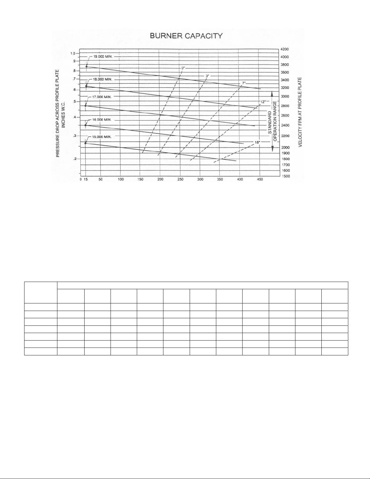
By using a magnehelic differential gauge across the burner profile will give you the pressure drop and using the
burner capacity chart will tell you what velocity you have through the profile. If the unit is operating between .45
W.C. and .65 W.C. it is considered to be within operating range, as the low air switch is factory set to make at .25
W.C. and the high profile switch is set to open at .95 W.C.
This should allow for a wide leeway before the unit will lock out due to low air / high air velocity across the
profile plate.
Under normal servicing the tubes from the air switch should be checked to insure they are free of any moisture or
dirt as this could cause the burner to lockout on the flame safeguard relay as both switches are in the flame rod
circuit.
If moisture is entering the tubes they may have to be repositioned to a lower area on the cabinet. Care must be
taken to insure that they will operate to shut down the unit if the velocity is out of the operating set points.
8
Page 10
CAPACITY 1000’S BTU PER HOUR PER FOOT OF BURNER
NAT & GAS APPROXIMATE 100° RISE
______ CAPACITY ____ ____ ____ FLAME LENGTH
FIGURE A CAPACITY & FLAME LENGTH WITH VARIOUS AIR FLOWS
TABLE I
Btu/hr. Required for Each 1,000 C.F.M. of Fan Rating (at 70° F.)
LOWEST EXPECTED OUTSIDE TEMPERATURE (°F)DESIRED
DELIVERY
TEMP.
70°F 99,000 94,000 88,000 82,000 77,000 71,000 66,000 61,000 55,000 49,000 44,000
75°F 104,000 98,000 93,000 87,000 82,000 76,000 71,000 66,000 60,000 54,000 49,000
80°F 108,000 103,000 98,000 92,000 87,000 81,000 76,000 70,000 65,000 59,000 54,000
85°F 113,000 107,000 102,000 96,000 91,000 85,000 80,000 75,000 69,000 64,000 59,000
90°F 117,000 111,000 106,000 101,000 96,000 90,000 85,000 80,000 74,000 69,000 64,000
95°F 121,000 116,000 111,000 105,000 100,000 94,000 89,000 84,000 79,000 73,000 68,000
100°F 125,000 120,000 115,000 109,000 104,000 99,000 94,000 89,000 83,000 78,000 73,000
-20° -15° -10° -5° 0° 5° 10° 15° 20° 25° 30°
9
Page 11

TYPE OF PROTECTION
SEE NOTE
TABLE II
PERMISSIBLE CLEARNCES WITH
SPECIFIED FORMS OF PROTECTION
(Clearance in Inches)
WHERE THE REQUIRED CLEARANCE WITH NO PROTECTION IS:
36 INCHES 18 INCHES 12 INCHES 6 INCHES
ABOVE SIDES
REAR
ABOVE SIDES
REAR
ABOVE SIDES
REAR
ABOVE SIDES
REAR
¼” asbestos millboard spaced out 1”*
28 gauge sheet metal on ¼” asbestos
millboard
28 gauge sheet metal space out 1”*
28 gauge sheet metal on 1/8” asbestos
millboard spaced out 1”*
1-½” asbestos cement covering on heating
appliance
¼” asbestos millboard on 1” rockwool batts
reinforced with wire mesh or equivalent
22 gauge sheet metal on 1” rockwool batts
reinforced with wire mesh or equivalent
¼” asbestos cement board or ¼” asbestos
millboard
¼” cellular asbestos
*Spacer shall be of non combustible material
LIMIT OF TOXIC VAPORS AND GASES
30 18 15 9 9 6 3 2
24 18 12 9 9 6 3 2
18 12 9 6 6 4 2 2
18 12 9 6 6 4 2 2
18 12 9 6 6 4 2 1
18 12 6 6 4 4 2 2
18 12 4 3 2 2 2 2
36 36 36 18 12 12 4 4
36 36 36 18 12 12 3 3
DURING NORMAL OPERATION OF THE HEATER, THE CONTENT OF TOXIC VAPORS AND
GASES IN THE TEMPERED AIR AT THE POINT OF DISCHARGE INTO THE BUILDING MUST BE
SUCH THAT NO IRRITATING EFFECTS ARE EVIDENT. THE INSTALLATION SHALL NOT BE
CONSIDERED ACCEPTABLE IF THE DISCHARGE OF TOXIC PRODUCTS IS KNOWN TO
EXCEED THE LIMITS SET OUT IN THE FOLLOWING TABLE.
SUBSTANCE PERCENT PPM SUBSTANCE PERCENT PPM
Acetaldehyde .001 10 Formaldehyde .000025 0.25
Carbon Dioxide .250 2500 Nitrogen Dioxide .0001 1
Carbon Monoxide .001 10 Sulfur Dioxide .00005 0.5
NOTE: At 100°F the CO2 concentration will be in the order of 2500 P.P.M.
10
Page 12

TYPICAL SEQUENCE OF OPERATION
(WARNING: FOR ACTUAL UNIT SEQUENCE OF OPERATION, PLEASE CONSULT SHOP DRAWINGS)
OSD SPRAY/DRY UNIT SEQUENCE OF OPERATION
PB1000 REMOTE PANEL c/w PROGRAMMABLE LOGIC CONTROLLER (PLC)
Spray Mode
1. Lighting Contactors are always energized as long as main disconnect is on and Booth Lights Switch is in “ON”
position. Spray Gun Solenoid (by others) is energized only in Spray Cycle.
2. System “ON” Push Button is pressed and released the fresh air dampers open fully (100%) and the return air
dampers close fully (0%). When the fresh air damper end switch makes the exhaust fan motor starter is energized.
3. After a delay (adjustable from PICO Controller) the Supply Fan Motor Starter is energized.
4. Once the supply fan air proving switch has made both the Spray Cycle Light and Supply Fan Light are energized.
5. Burner is controlled by Burner Switch located on Remote Panel.
Dry Mode
Note: A set of normally closed contacts from a fire alarm are placed in series with PLC Input No. 4 so that in the event
of a fire the Dry Cycle is shut down and the system reverts back to the Spray Cycle venting smoke to the outdoors
through the unit.
1. Dry Mode Push Button is pressed and released. Spray Cycle Light is de-energized and Spray Gun Solenoid (by
others) is de-energized. Burner is still active (if burner switch is “ON”) discharging at Remote Temperature Selector
Set Point.
2. Purge Cycle Timer (set to 180 seconds, adjustable from PICO Controller inside Remote Panel) is energized while
simultaneously energizing the Purge Cycle Light.
3. After 180 seconds, the Purge Cycle Light is de-energized. The Dry Timer (set to paint specifications, adjustable
from PICO Controller inside Remote Panel) is energized which will energize the override temperature set point on
the Potentiometer located on the back of the Remote Panel Mounted Remote Temperature Selector, and the Dry
Cycle Light.
4. The fresh air damper repositions for 20% fresh air and the return air damper repositions for 80% return air.
5. On expiration of the paint specification dry time, the override temperature set point on the Potentiometer and the Dry
Cycle Light are de-energized.
Cool Down Mode
1. The Cool Down Timer (adjustable from the PICO Controller inside Remote Panel) is energized while simultaneously
energizing the Cool Down Cycle Light.
2. The dampers reposition for 100% fresh air and 0% return air.
3. The burner (if Burner Switch is in “ON” Position) will discharge temperature as set at the Maxitrol spray mode set
point.
4. After the Cool Down Timer times out the system will shut down.
Timer Settings (Operator Programmable)
TD-1 Delay Exhaust Timer, Set 3 seconds (in PICO Controller)
TD-2 Booth Door Delay Timer 5-30 seconds (in PICO Controller, set 15 seconds)
TD-3 Purge Cycle Timer Set 3 minutes (in PICO Controller)
TD-4 Dry Cycle Timer set as per Paint Specifications (in PICO Controller)
TD-5 Cool-Down Cycle Timer Set 3 minutes (in PICO Controller)
Additional Notes
1. In spray mode if any of the booth doors are opened the spray gun solenoid valve will be de-energized after the door
delay timer has timed out (Operator Programmable in PICO Controller, 5-30 seconds).
2. In the dry mode if any of the booth doors are opened the unit will shut down after the door delay timer has timed out
(Operator Programmable in PICO Controller, 5-30 seconds).
11
Page 13

DUAL AIR/TEMPERATURE SEQUENCE OF OPERATION
PB3000A REMOTE PANEL c/w PROGRAMMABLE LOGIC CONTROLLER (PLC)
Spray Mode
1. Three-position damper is powered continuously. Lighting Contactors (by others) are always energized as long as
main disconnect is on and Booth Lights Switch is in “ON” position. Spray Gun Solenoid (by others) is energized
only in Spray Cycle.
2. System “ON” Push Button is pressed and released, energizing and supplies power to the Maxitrol Amplifier. Three
position damper motor opens the damper to 100% fresh air. Output 1 energizes the profile damper motor.
3. When the profile damper motor end switch is engaged, the High Speed Exhaust (Spray) Fan Starter is energized and
closes the High Exhaust Fan Air Proving Switch.
4. Delay Exhaust Start Timer (Set to 4 seconds) is energized.
5. After 4 seconds the Supply Fan Motor Starter Coil is energized, Spray Cycle Light and Supply Fan Light are
energized.
Dry Mode
Note: A set of normally closed contacts from a fire alarm are placed in series with PLC Input No. 4 so that in the event
of a fire the Dry Cycle is shut down and the system reverts back to the Spray Cycle venting smoke to the outdoors
through the unit.
1. Dry Mode Push Button is pressed and released. Spray Cycle Light is de-energized and Spray Gun Solenoid (by
others) is de-energized. Burner is still active discharging at 75°F.
2. Purge Cycle Timer (set to 180 seconds, adjustable from Operator Interface) is energized while simultaneously
energizing the Purge Cycle Light.
3. After 180 seconds, the Purge Cycle Light is de-energized. The Dry Timer (set to paint specifications, adjustable
from Operator Interface ) is energized which will energize the Spray/Dry Switch Over Timer (set to 10-20 seconds),
relay R1, and the Dry Cycle Light.
4. After 10-20 seconds, the contacts on the Maxitrol Amplifier switch to set point 2 (preheat).
5. When R1 relay is energized, the three position damper motor travels the damper to the mid-position. The profile
damper motor is de-energized. The damper motor end switch de-energizes the High Speed Exhaust Fan Starter.
6. The High Exhaust Fan Air Proving Switch drops out, the Low Exhaust Speed Fan Air Proving Switch makes and the
Season Switch is disabled.
7. After 120 seconds the contacts on the Maxitrol amplifier switch to set point 3 (drying).
8. Expiration of the paint specification dry time, Dry Cycle Light, Spray/Dry Switch Over Timer, and relay R1 are de-
energized.
9. The three position damper returns to 100% fresh air. Unit will remain on until the System “OFF” Push Button is
manually pressed and released.
Timer Settings
TD-1 Delay Exhaust Start Timer 4 Seconds (in PLC)
TD-2 Low Fire Delay Timer 20 Seconds (in unit panel)
TD-3 Purge Cycle Timer 180 Seconds (in PLC, Operator Programmable)
TD-5 Spray/Dry Switch Over Timer 10-20 Seconds (in PB3000 Panel)
TD-6 Dry Mode Preheat Timer 120 Seconds (in PLC)
Dry Timer set as per Paint Specifications (in PLC, Operator Programmable)
Limit Settings
High Limit Spray = 165°F, High Limit Dry = 200°F
12
Page 14

RECIRCULATION SEQUENCE OF OPERATION
PB3000A REMOTE PANEL c/w PROGRAMMABLE LOGIC CONTROLLER (PLC)
Spray Mode
1. Three-position damper is powered continuously. Lighting Contactors (by others) are always energized as long as
main disconnect is on and Booth Lights Switch is in “ON” position. Spray Gun Solenoid (by others) is energized
only in Spray Cycle.
2. System “ON” Push Button is pressed and released, energizing and supplies power to the Maxitrol Amplifier. Three
position damper motor opens the damper to 100% fresh air.
3. When three position damper motor end switch is engaged, the High Speed Exhaust (Spray) Fan Starter is energized
and closes the High Exhaust Fan Air Proving Switch.
4. Delay Exhaust Start Timer (Set to 4 seconds) is energized.
5. After 4 seconds the Supply Fan Motor Starter Coil is energized, Spray Cycle Light and Supply Fan Light are
energized.
Dry Mode
Note: A set of normally closed contacts from a fire alarm are placed in series with PLC Input No. 4 so that in the event
of a fire the Dry Cycle is shut down and the system reverts back to the Spray Cycle venting smoke to the outdoors
through the unit.
1. Dry Mode Push Button is pressed and released. Spray Cycle Light is de-energized and Spray Gun Solenoid (by
others) is de-energized. Burner is still active discharging at 75°F.
2. Purge Cycle Timer (set to 180 seconds, adjustable from Operator Interface) is energized while simultaneously
energizing the Purge Cycle Light.
3. After 180 seconds, the Purge Cycle Light is de-energized. The Dry Timer (set to paint specifications, adjustable
from Operator Interface ) is energized which will energize the Spray/Dry Switch Over Timer (set to 10-20 seconds),
relay R1, and the Dry Cycle Light.
4. After 10-20 seconds, the contacts on the Maxitrol Amplifier switch to set point 2 (preheat).
5. When R1 relay is energized, the three position damper travels the damper to the mid-position. The damper motor
end switch de-energizes the High Speed Exhaust Fan Starter.
6. The High Exhaust Fan Air Proving Switch drops out, the Low Exhaust Speed Fan Air Proving Switch makes and the
Season Switch is disabled.
7. After 2 minutes the contacts on the Maxitrol Amplifier switch to set point 3 (drying).
8. Expiration of the paint specification dry time, Dry Cycle Light, Spray/Dry Switch Over Timer, and relay R1 are de-
energized.
9. The three position damper returns to 100% fresh air. Unit will remain on until the System “OFF” Push Button is
manually pressed and released.
Timer Settings
TD-1 Delay Exhaust Start Timer 4 Seconds (in PLC)
TD-2 Low Fire Delay Timer 20 Seconds (in unit panel)
TD-3 Purge Cycle Timer 180 Seconds (in PLC, Operator Programmable)
TD-5 Spray/Dry Switch Over Timer 10-20 Seconds (in PB3000 Panel)
TD-6 Dry Mode Preheat Timer 120 Seconds (in PLC)
Dry Timer set as per Paint Specifications (in PLC, Operator Programmable)
Limit Settings
High Limit Spray = 165°F, High Limit Dry = 200°F
13
Page 15

DUAL AIR/TEMPERATURE SEQUENCE OF OPERATION
PB4000 REMOTE PANEL c/w PROGRAMMABLE LOGIC CONTROLLER (PLC)
Spray Mode
1. Three-position damper is powered continuously. Lighting Contactors (by others) are always energized as long as
main disconnect is on and Booth Lights Switch is in “ON” position. Spray Gun Solenoid (by others) is energized
only in Spray Cycle.
2. System “ON” Push Button is pressed and released, energizing and supplies power to the Maxitrol Amplifier. Three
position damper motor opens the damper to 100% fresh air.
3. When the profile damper motor end switch is engaged, the High Speed Exhaust (Spray) Fan Starter is energized and
closes the High Exhaust Fan Air Proving Switch.
4. Delay Exhaust Start Timer (Set to 4 seconds) is energized.
5. After 4 seconds the Supply Fan Motor Starter Coil is energized, Spray Cycle Light and Supply Fan Light are
energized.
Dry Mode
Note: A set of normally closed contacts from a fire alarm are placed in series with PLC Input No. 4 so that in the event
of a fire the Dry Cycle is shut down and the system reverts back to the Spray Cycle venting smoke to the outdoors
through the unit.
1. Dry Mode Push Button is pressed and released. Spray Cycle Light is de-energized and Spray Gun Solenoid (by
others) is de-energized. Burner is still active discharging at 75°F.
2. Purge Cycle Timer (set to 180 seconds, adjustable from Operator Interface) is energized while simultaneously
energizing the Purge Cycle Light.
3. After 180 seconds, the Purge Cycle Light is de-energized. The Dry Timer (set to paint specifications, adjustable
from Operator Interface ) is energized which will energize the Spray/Dry Switch Over Timer (set to 10-20 seconds),
relay R1, and the Dry Cycle Light.
4. After 10-20 seconds, the contacts on the Maxitrol Amplifier switch to set point 2 (preheat).
5. When R1 relay is energized, the three position damper motor travels the damper to the mid-position. The profile
damper motor is de-energized. The damper motor end switch de-energizes the High Speed Exhaust Fan Starter.
6. The High Exhaust Fan Air Proving Switch drops out, the Low Exhaust Speed Fan Air Proving Switch makes and the
Season Switch is disabled.
7. After 120 seconds the contacts on the Maxitrol amplifier switch to set point 3 (drying).
8. Expiration of the paint specification dry time, Dry Cycle Light, Spray/Dry Switch Over Timer, and relay R1 are de-
energized.
9. The three position damper returns to 100% fresh air.
Cool Down Mode
1. The profile damper motor is energized opening the profile to 100%.
2. The exhaust fan reverts back to high speed.
3. The unit will run on the low temperature setting (set point 1) and high cfm until the Cool Down Time has expired.
4. On expiration of the cool down time the unit shuts down.
Timer Settings
TD-1 Delay Exhaust Start Timer 4 Seconds (in PLC)
TD-2 Low Fire Delay Timer 20 Seconds (in unit panel)
TD-3 Purge Cycle Timer 180 Seconds (in PLC, Operator Programmable)
TD-5 Spray/Dry Switch Over Timer 10-20 Seconds (in PB3000 Panel)
TD-6 Dry Mode Preheat Timer 120 Seconds (in PLC)
Dry Timer set as per Paint Specifications (in PLC, Operator Programmable)
Limit Settings
High Limit Spray = 165°F, High Limit Dry = 200°F
14
Page 16

RECIRCULATION SEQUENCE OF OPERATION
PB4000 REMOTE PANEL c/w PROGRAMMABLE LOGIC CONTROLLER (PLC)
Spray Mode
1. Three-position damper is powered continuously. Lighting Contactors are always energized as long as main
disconnect is on and Booth Lights Switch is in “ON” position. Spray Gun Solenoid (by others) is energized only in
Spray Cycle.
2. System “ON” Push Button is pressed and released, energizing and supplies power to the Maxitrol Amplifier. Three
position damper motor opens the damper to 100% fresh air.
3. When the fresh air damper motor end switch is engaged, the High Speed Exhaust (Spray) Fan Starter is energized
and closes the High Exhaust Fan Air Proving Switch.
4. Delay Exhaust Start Timer (Set to 4 seconds) is energized.
5. After 4 seconds the Supply Fan Motor Starter Coil is energized, Spray Cycle Light and Supply Fan Light are
energized.
Dry Mode
Note: A set of normally closed contacts from a fire alarm are placed in series with PLC Input No. 4 so that in the event
of a fire the Dry Cycle is shut down and the system reverts back to the Spray Cycle venting smoke to the outdoors
through the unit.
1. Dry Mode Push Button is pressed and released. Spray Cycle Light is de-energized and Spray Gun Solenoid (by
others) is de-energized. Burner is still active discharging at 75°F.
2. Purge Cycle Timer (set to 180 seconds, adjustable from Operator Interface) is energized while simultaneously
energizing the Purge Cycle Light.
3. After 180 seconds, the Purge Cycle Light is de-energized. The Dry Timer (set to paint specifications, adjustable
from Operator Interface ) is energized which will energize the Spray/Dry Switch Over Timer (set to 10-20 seconds),
relay R1, and the Dry Cycle Light.
4. After 10-20 seconds, the contacts on the Maxitrol Amplifier switch to set point 2 (preheat).
5. When R1 relay is energized, the three position damper motor travels the damper to the mid-position. The damper
motor end switch de-energizes the High Speed Exhaust Fan Starter.
6. The High Exhaust Fan Air Proving Switch drops out, the Low Exhaust Speed Fan Air Proving Switch makes and the
Season Switch is disabled.
7. After 120 seconds the contacts on the Maxitrol amplifier switch to set point 3 (drying).
8. Expiration of the paint specification dry time, Dry Cycle Light, Spray/Dry Switch Over Timer, and relay R1 are de-
energized.
9. The three position damper returns to 100% fresh air.
Cool Down Mode
1. The three position damper motor is energized opening the fresh air damper to 100%.
2. The exhaust fan reverts back to high speed.
3. The unit will run on the low temperature setting (set point 1) and high cfm until the Cool Down Time has expired.
4. On expiration of the cool down time the unit shuts down.
Timer Settings
TD-1 Delay Exhaust Start Timer 4 Seconds (in PLC)
TD-2 Low Fire Delay Timer 20 Seconds (in unit panel)
TD-3 Purge Cycle Timer 180 Seconds (in PLC, Operator Programmable)
TD-5 Spray/Dry Switch Over Timer 10-20 Seconds (in PB3000 Panel)
TD-6 Dry Mode Preheat Timer 120 Seconds (in PLC)
Dry Timer set as per Paint Specifications (in PLC, Operator Programmable)
Limit Settings
High Limit Spray = 165°F, High Limit Dry = 200°F
15
Page 17

MAINTENANCE
Regular maintenance is necessary to ensure the efficient operation and long life of this unit. This maintenance should be
performed by, or supervised by, qualified service personnel. A maintenance schedule should be prepared for the unit
based on its application and location.
RECOMMENDED MONTHLY MAINTENANCE
1. Check for loose connections in the wiring.
2. Check the voltage at the unit while it is in operation.
3. Check motor amperage draws against rating plate values.
4. Inspect all contactors to ensure that they are clean and making good contact.
5. Check all fittings, valves and lines for leaks.
6. Check the burner; clean and adjust if necessary.
7. Check the flame sensor; clean if necessary.
8. Check the fuel supply pressure to the unit.
9. On gas fired units, check the manifold pressure.
10. Clean or replace air filters if necessary. Replace filters only with type equivalent to those supplied with the unit by
the factory.
11. Check all damper, linkages and damper actuators; adjust and tighten as required.
12. Check all belts; adjust or replace as necessary.
13. Check operation of all safety controls.
RECOMMENDED YEARLY MAINTENANCE
1. Perform the monthly maintenance recommended.
2. Inspect blower wheels and housing; clean if necessary.
3. Inspect all set screws on blower wheels and pulleys to ensure that they are secured to their respective shafts.
4. Check ignition spark and adjust gap if necessary.
5. Inspect and clean ignition electrodes.
6. Check flame supervisor relay.
7. Inspect all operating and safety controls; clean and replace if necessary.
8. Inspect the header box and secondary tubes through the access panels provided. Check for carbon deposits, soot,
scale, or rust; clean as required. Check condition of flue pipe.
9. Clean the primary combustion chamber.
10. Clean the burner.
NOTE: Refer to manufacturer literature provided for maintenance requirements of optional equipment.
16
Page 18

BEARING INSTALLATION AND MAINTENANCE
NOTE: To prevent premature failure – please ensure greasing instructions below are applied. As well, tighten
bearing set screws, collars, and wheel lugs every four to six months.
ENGINEERING – BALL & ROLLER BEARINGS LUBRICATION
For bearings that are equipped with a hydraulic grease fitting threaded into the housing for ease of lubrication, the
proper amount of lubricant in the bearing is important. Both excessive and inadequate lubrication may cause
failure. The bearings should be re-lubricated while they are rotating (if it is safe to do so); the grease should be
pumped in slowly until a slight bead forms around the seals. The bead in addition to acting as an indicator of
adequate re-lubrication provides additional protection against the entry of foreign matter and helps flush out
contaminates in the bearing.
By the time the slight bead is formed, it will be noticed that the bearing temperature will rise. It is not uncommon
for the temperature to rise as much as 30 degrees Fahrenheit after re-lubrication. If necessary to re-lubricate while
the bearing is idle, refer to the recommended re-lubrication grease chart tables on the following page for various
sizes of the bearings.
Lubricant-Standard Bearings:
All bearing units are pre-lubricated at the factory with a lithium soap grease which is compatible with multi-purpose
grease readily available from local suppliers. The lubricant selected for factory lubrication uses a highly refined
mineral oil with a high viscosity index, thickened with lithium soap to conform to NLGI grade 2 consistency. A
suitable additive package is added to protect the highly polished rolling contact surfaces from corrosion and
oxidation of the lubricant. The lubricant is satisfactory for an operating temperature range of –30° F to 250° F.
Select standard industrial grade greases that conform to the following specification for optimum bearing
performance:
General Duty Ball & Roller;
58-75 SUS @ 210° F
450-750 SUS @ 100° F
Premium Duty Ball & Roller;
68-75.1 SUS @ 210° F
600-750 SUS @ 100° F
Heavy Duty Roller Bearing;
82 SUS @ 210° F
886 SUS @ 100° F
NOTE: For heavy loaded roller bearing applications, grease with EP additives are often recommended for
optimum performance.
17
Page 19

TABLE III: RECOMMENDED LUBRICATION
Ball Bearings Roller Bearings
Shaft Size
(inches)
1/4 to 3/16 0.03 1-3/16 to 1-1/4 0.1
1/2 to 3/4 0.1 1-3/8 to 1-7/16 0.22
1-1/4 to 1-1/2 0.15 1-1/2 to 1-11/16 0.32
1-11/16 to 1-15/16 0.2 1-3/4 to 2 0.5
2 to 2-7/16 0.3 2 to 2-3/16 0.55
2-1/2 to 2-15/16 0.5 2-1/4 to 2-1/2 0.65
3 to 3-7/16 0.85 2-11/16 to 3 0.85
3-1/2 to 4 1.5 3-3/16 to 3-1/2 1.25
- - 3-15/16 to 4 2.5
- - 4-7/16 to 4-1/2 3.1
Frequency of re-lubrication depends upon operating conditions. The bearing operating temperature is the best index for
determining a re-lubrication schedule. The following chart gives the frequency of re-lubrication based upon continuous
operation for various operating temperatures and can be used as a satisfactory guide for determining when bearings
should be re-lubricated.
Grease Charge
(ounces)
Shaft Size
(inches)
Grease Charge
(ounces)
TABLE IV. LUBRICATION FREQUENCY
Speed Temperature Cleanliness Greasing Interval
100 RPM Up to 120° F Clean 5 months
500 RPM Up to 130° F Clean 2 months
1000 RPM Up to 210° F Clean 2 weeks
1500 RPM Over 150° F Clean Weekly
Any speed Up to 150° F Dirty 1 week to 1 month
Any speed Over 150° F Dirty Daily to 1 week
Any speed Any temperature Very dirty Daily to 1 week
Any speed Any temperature Extreme conditions Daily to 1 week
18
Page 20

TENSIONING V-BELT DRIVES
1. Ideal tension is the lowest tension at which the belt will not slip under peak load conditions.
2. Check tension frequently during the first 24-48 hours of operation.
3. Over-tensioning shortens the belt and bearing life.
4. Keep belts free from foreign material that may cause slip.
5. Make V-drive inspection on a periodic basis. Tension when slipping. Never apply belt dressing as this will
damage the belt and cause early failure.
Check and tighten belt tension. The following procedure is recommended for tightening belts:
a) Measure span “X” shown in Figure A.
b) At the center of span length “X”, apply a force perpendicular to the span and large enough to deflect belt
1/64” for each inch of span length. Example- the required deflection for a 40” span would be 40/64” or
5/8”.
c) Compare the force applied with the values given in Table III. If force is between the minimum and
maximum range shown, the drive tension should be satisfactory. A force below the minimum value
indicates an under tightened belt and force that exceeds the maximum value indicates an over tightened
belt.
FIGURE A
S
P
A
N
L
E
N
G
T
H
X
FORCE
DEFLECTION 1/64"
PER INCH OF SPAN
TABLE V
BELT CROSS MOTOR PULLEY DEFLECTION FORCE
SECTION PITCH DIAMETER MINIMUM MAXIMUM
(Marked on Belt)
3.0” - 3.6” 2.62lbs. 3.25lbs.
A 3.8” - 4.8” 3.0lbs. 4.0lbs.
5.0” - 7.0’ 3.25lbs. 5.0lbs.
3.4” - 4.2” 3.0lbs. 5.0lbs.
B 4.4” - 5.6’ 4.0lbs. 5.87lbs.
5.8” - 8.6” 5.25lbs. 7.87lbs.
19
Page 21

DIRECT FIRED WARRANTY
The warranty on the ICE Manufacturing Direct Gas Fired Make-up Air Units are one (1) year from installation
date or 15 months from date of shipment from our factory.
Our warranty applies for original shipment on all parts and components fabricated by or installed by us with the
exception of air filters, flame rods, igniters, and blower belts.
Within the one year warranty, replacement parts will be shipped collect and charged to customer account with
credit being issued after receipt of, and examination of the returned parts: freight prepaid to the factory.
This warranty does not include freight, labor, or sales taxes, that may be incurred by the purchasers and is
subject to the following conditions:
1) The unit shall be installed by a qualified heating contractor in accordance with the provisions of the service
manual.
2) The unit shall have been installed in accordance with all provincial and local codes.
3) The unit shall have been subject to only normal use in service and shall not have been misused, neglected,
altered or otherwise damaged.
4) The unit shall have been operated within its published capacity and with the prescribed fuel.
5) All automatic controls shall have been operative at all times.
6) The unit has not been allowed to exceed its proper temperature limits due to control malfunction or
inadequate air circulation.
7) There is no evidence of tampering or deliberate destruction.
No representative of ICE or any of its distributors or dealers is authorized to assume for ICE any other
obligations or liability in connection with this product, nor alter the terms of this warranty in anyway. This
warranty is limited to the express provisions contained herein and does not extend to liability for labor costs
incurred in replacing defective parts.
Authorization to return any alleged defective parts must be obtained from the factory before the part is
transported and the owner shall prepay the transportation charges for any alleged defective parts. ICE will not
accept charges for parts purchased unless the conditions of this warranty have been satisfied.
The express warranties herein contained are in lieu of any other warranties, expressed or implied, including the
warranty of merchantability and of fitness for any particular purpose. ICE shall not be liable for damages,
including special, incidental, or consequential damages arising out of or in connection with the performance of
the Direct Gas Fired Make-up Air Units, or its use by the owner. ICE liability is limited exclusively to repair
and or replacement or the defective part. Parts can be obtained from ICE Manufacturing, 51 Aikins Street,
Winnipeg, Manitoba, R2W 4E3, on the basis that credit will be issued if defective parts returned qualify for
replacement pursuant to the terms and conditions of this warranty.
20
Page 22

DISTRIBUTION DUCT
By
Rev
Revision Description
Date
SERIES
SN
JUNE 24/98
-
DRW. NO.
JOB NO. REVDATE
INSULATION
SECTION
BURNER BLOWER
CONTROL
DISCHARGE
PANEL
AIR
16" MIN.
SCALEISSUED BY
1:16 FIG. 1
DRAWN BY
TITLE
DIRECT GAS FIRED MAKE-UP AIR HEATERS
INSTALLATIONS AND SERVICE INSTRUCTIONS
JV
CHK. BY
OSD
FIGURE #1
DIRECT GAS FIRED MAKE-UP AIR HEATERS
SECTION
MIX BOX/V-BANK FILTER
SECTION
LOUVERED INLET
FRESH
DAMPER
AIRFLOW
AIR FLOW
RETURN
SLEEPER ROOF CURB
DISTRIBUTION DUCT
Page 23

SECTION
SERIES
SN
JUNE 25/98
-
BURNER BLOWER
CONTROL
PANEL
AIRFLOW
SUPPLY
UNIT
BASE FRAME
WOODEN NAILER
CANT STRIP (BY OTHERS)
INSULATION (BY OTHERS)
ROOF CURB DETAIL
DRW. NO.
JOB NO. REVDATE
SCALEISSUED BY
2
1:18 FIG. 2
SECTION
MIX BOX/V-BANK FILTER
SECTION
LOUVERED INLET
FRESH
DAMPER
AIRFLOW
AIR FLOW
RETURN
ROOF CURB
SLEEPER
FLASHING
(BY OTHERS)
NEOPRENE GASKET
FIGURE #2
OR CAULKING (BY OTHERS)
BOTTOM DISCHARGE
BY OTHERS
DUCT COLLAR
(BY OTHERS)
ROOFING PAPER
4
1
3
SLEEPER ASSEMBLY
TITLE
DRAWN BY
DIRECT GAS FIRED MAKE-UP AIR HEATERS
INSTALLATIONS AND SERVICE INSTRUCTIONS
JV
CHK. BY
OSD
SLEEPER DETAIL
MATERIAL = 16 GA. CB.
CURB
ENDS
DUCT COLLAR
BY OTHERS
SLEEPER
CURB
SIDES
DUCT
ANGLE
SUPPORT
CURB
CENTER
BRACING
ONE EXAMPLE OF CURBING
Page 24

ANGLE
By
Rev
Revision Description
Date
SERIES
SN
JUNE 10/98
-
FRAME
ANCHOR
TO WALL
UNIT
INLET TO
INSULATED
AIR
FRESH
ANGLE
FRAME
DUCT
LINER
FRESH AIR
DUCT
BIRDSCREEN
GENEROUSLY
SIZED
DRW. NO.
JOB NO. REVDATE
SCALEISSUED BY
NTS FIG. 3 & 4
DRAWN BY
TITLE
DIRECT GAS FIRED MAKE-UP AIR HEATERS
INSTALLATIONS AND SERVICE INSTRUCTIONS
JV
CHK. BY
48" MINIMUM
ON ALL TWIN BLOWERS UNIT WITH DUCT A STUB
DISCHARGE DUCT MUST BE INSTALLED WITH A
MINIMUM LENGTH OF 48".
FIGURE #3 FIGURE #4
WALL
ANGLE
FRAME
ANCHOR
TO WALL
INLET LOUVER
FLUSH MOUNTED
ANGLE
FRAME
FRESH AIR DUCT TO UNIT
DUCT
LINER
DUCT
FRESH AIR
SIZED
OSD
MAKE-UP AIR UNIT
INLET
HOOD
AIR
FRESH
BIRDSCREEN
GENEROUSLY
Page 25

STAINLESS STEEL
SERIES
SN
JUNE 17/98
-
SCREW
10-24x9/16 LONG
GASKET ENDS
BUTTED
END BAFFLE
AND REPLACE WITH 10-24x3/8 LONG
TO REPLACE RIVETED BAFFLE PLATES
CHISEL OFF RIVETS FROM FLAT SIDE
STAINLESS STEEL SCREWS AND NUTS
RIVETS
THREADED INLET
FLANGE
NO. 1350
NO. 1350
5/16-18x2" LONG
BOLT NUT AND
LOCKWASHER
SECTION
12" STRAIGHT
12" SECTION
5/16-18x1 1/4 LONG BOLT
JOINTS
LEAK PROOF
THIN COAT OF FURNITURE
SEAL CASTING JOINTS WITH
NUT AND LOCKWASHER
FR
4
3
3
CEMENT OR GRAPHIC PASTE
* FOR USE WITH HONEYWELL 0624A
IGNITER, CHANGE SPARK GAP TO
1/8" TO 3/16"
5
8
6
7-1/2 LONG
(NOT INCLUDED)
FLAME ROD
1/4" NPT RIGHT HAND
1
8
3
1 1/16
1
16
2
1 7/32
SI
3
8
3
FLAME ROD LOCATION
DRW. NO.
JOB NO. REVDATE
SCALEISSUED BY
NTS FIG. 5
DRAWN BY
TITLE
MIDCO DIRECT FIRED GAS BURNER
PILOT ARRANGEMENTS w/ FLAME ROD
CHK. BY
AND IGNITOR
JV
3/8
SPARK ROD
WITH FLAME ROD AND IGNITOR
EXPOSE INSULATOR
NOT MORE THAN
1/8 INCH
MIDCO DIRECT FIRED GAS BURNER PILOT ARRANGEMENT
ROD
ASSEMBLY
GROUND
ADAPTO PILOT
SLEEVES
ELECTRODE
FLAME ROD
ASSEMBLE BURNER
ASSEMBLY
ASSEMBLY
SPARK ROD
ARE FLUSH
SECTIONS SO THAT
GASKET SURFACES
CLAMP
BAFFLE
PILOT TUBE
1/2"NPT BLIND
BLANK FLANGE
PILOT INLET FITTING
(FOR PROP. CONTAINS
RESTRICTING ORIFICE)
GASKET
BAFFLE
MOUNTING HOLE
SETTING
3"
32
SPARK GAP *
BURNER PORT
PLUG FIRST
SPARK ROD
PILOT TUBE
OF IST PORT
1"
16
FOR FLAME ROD,
1/2"x1/4" BUSHING
LEFT-HAND FLAME
OR "UV" SCANNER
LOCATE EDGE OF SPARK ROD 1/16"
FORWARD OF FIRST PILOT AS SHOWN
ROD LOCATION
FOR FLAME ROD,
1/2"x1/4" BUSHING
LEFT-HAND FLAME
OR "UV" SCANNER
# 23739
IGNITOR
14 mm SPARK
ROD LOCATION
(SPECIFY # 238481
FLAME ROD LOCATION
1/4" NPT RIGHT HAND
# 23739
(SPECIFY # 238481
1/8" NPT PILOT
TEST CONN.
1/8" NPT
IGNITOR
14 mm SPARK
1/8" NPT PILOT
GAS CONNECTION
OSD
END FLANGE SETS
# 62-23809 STRAIT-IN & R-H ANGLED FR.
# 62-23849 STRAIT-IN, R-H AND L-H FR.
GAS CONNECTION
END PLATE SETS
# 62-23808 STRAIT-IN & R-H ANGLED FR.
# 62-23848 STRAIT-IN, R-H AND L-H FR.
COMBUSTION
BAFFLE
BURNER
SECTION
CAST IRON
GAS
BUILT-IN PILOTS
PORTS
AS A PILOT.
WITH PILOT GAS CONNECTION LEADING TO A CHANNEL
OF THE MAIN BURNER. EITHER MAY THERFORE BE USED
BOTH THE END PLATE ILLUSTRATED ABOVE AND THE 1-1/4"
END INLET FLANGE IN THE SKETCHES BELOW ARE EQUIPPED
5
8
6
13
16
7
3
1
16
1
4
3
END PLATE
# 62-22739
Page 26

SECTION
By
Rev
Revision Description
Date
SERIES
MAY 8/2001
-
BURNER BLOWER
INSULATION
CONTROL
AIR
DISCHARGE
PANEL
FIGURE #6
DISTRIBUTION DUCT
DRW. NO.
JOB NO. REVDATE
SCALEISSUED BY
NTS FIG. 6
JV
DRAWN BY
TITLE
DIRECT GAS FIRED MAKE-UP AIR HEATERS
SUSPENSION HOLES DETAIL FOR INDOOR UNIT
JV
CHK. BY
OSD
SECTION
MIX BOX/V-BANK FILTER
FRESH AIR
FLOW
INSULATION
DAMPER
RETURN AIR
FLOW
DIRECT GAS FIRED MAKE-UP AIR HEATERS
AND HANDLED WITH THESE HOLES
WHEN MOVING UNIT INTO POSITION
TO BE SUSPENDED FROM CEILING.
UNIT MUST BE LIFTED
5/8"Ø
FOR HOLE SIZE)
(FOR LARGE UNITS
CONSULT FACTORY
BE SUSPENDED FROM THE CEILING.
THE BASERAIL SO THAT THE UNIT MAY
THESE HOLES ARE PROVIDED TO ALLOW
SUSPENSION RODS TO BE INSERTED THRU
DISTRIBUTION DUCT
LIFTING LUG DETAIL
 Loading...