

Page 1
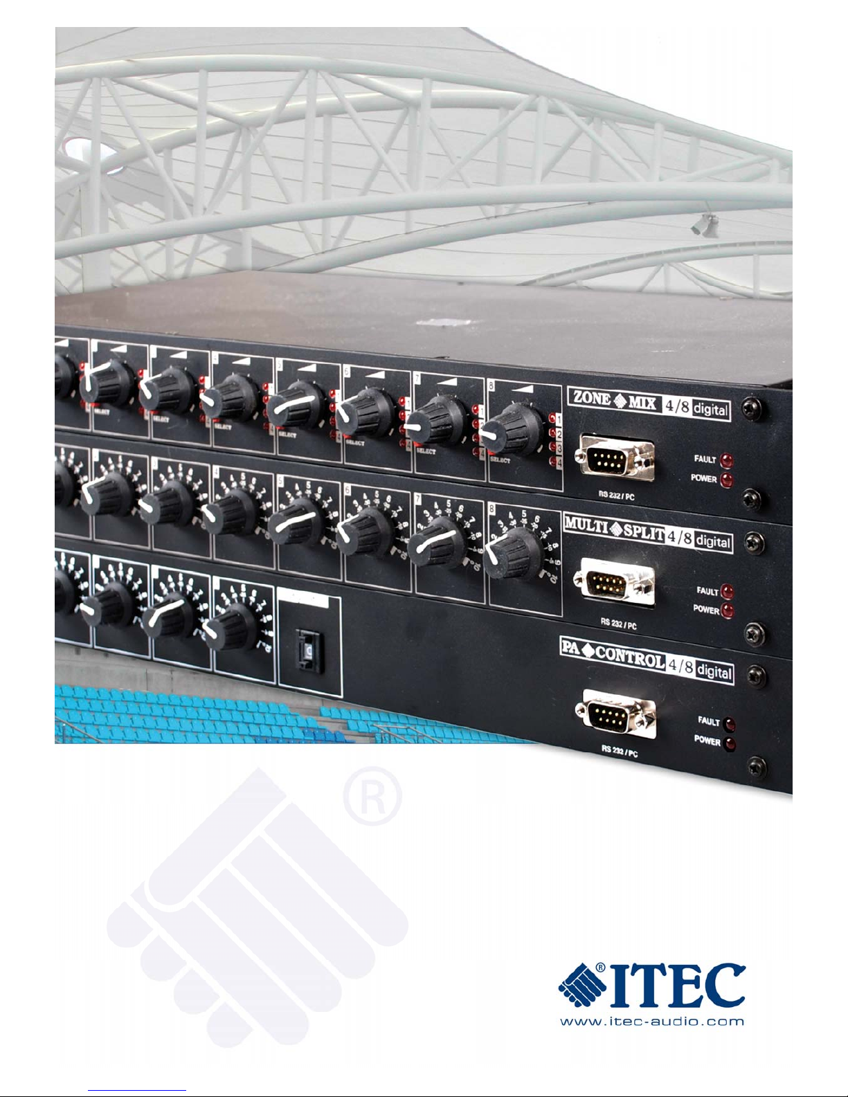
MULTISPLIT / PA-CONTROL / ZONE-MIX 4/8 DIGITAL
MANUAL VERSION 1.0, OKTOBER 2007
PART 1: HARDWARE DESCRIPTION
Page 2

MULTISPLIT / PA-CONTROL / ZONE-MIX 4/8 DIGITAL
www.itec-audio.com MULTISPLIT / PA-CONTROL / ZONE-MIX 4/8 DIGITAL
Dear Customer!
Our main aim in developing new products is to make life easier for you. Designed with a
focus on practical usage, our products aim to simplify the work of both the end users – who
work with the devices as part of a complete installation – and the planners and engineers
whose job it is to install and set up the equipment according to the customers’ wishes.
Many years’ experience in the field of sound reinforcement have given us an in-depth
understanding of what customers want: A multi-functional device that provides technicians
with a comprehensive range of signal adjustments yet features user-friendly controls for
easy, convenient use within the completed sound system.
The devices of the Multisplit / PA-Control / Zone-Mix 4/8 digital series represent the
culmination of our extensive experience in the field of sound system engineering. Engineers
can conveniently configure the devices via a PC and apply a wide range of sound effects
without the need for additional equipment. And the end user receives a clearly laid out and
easy-to-use system with a convenient, simple and logical arrangement of controls.
Adjustments to the device’s configuration are possible only within strictly defined limits, which
virtually eliminates the possibility of operator errors.
Like the hardware, the configuration software ITEC-SplitDesign is clearly structured and
easy to use. The Multi-Split unit’s flash memory holds up to 10 complete configurations,
which users can load as required.
Unlike comparable products, ITEC’s devices work with an analog signal path (except for the
optional DSP output modules), which is fully digitally controlled. The processors control the
VCAs, measure levels and transmitters and switch the signals. The analog signal path
concept is a decisive factor in the devices’ exceptional sound quality, especially their
outstanding signal-to-noise ratio and dynamics and their low harmonic distortion of low signal
levels.
To get the best quality and performance from this product, please observe the installation
and configuration instructions contained in this manual.
Your ITEC Audio Team
2
Page 3

MULTISPLIT / PA-CONTROL / ZONE-MIX 4/8 DIGITAL
www.itec-audio.com MULTISPLIT / PA-CONTROL / ZONE-MIX 4/8 DIGITAL
TABLE OF CONTENTS
PART 1: HARDWARE MANUAL
Dear Customer! ......................................................................................................................2
SAFETY PRECAUTIONS........................................................................................................4
PACKAGE CONTENT.............................................................................................................5
PART 1: HARDWARE MANUAL ............................................................................................6
OPERATOR CONTROL AND DISPLAY ELEMENTS ON FRONT.....................................6
1. Power LED ..................................................................................................................................6
2. Multifunction LED display............................................................................................................ 6
3. Rotary switches 1 to 8................................................................................................................. 6
4. PC interface................................................................................................................................. 7
5. Device status............................................................................................................................... 7
6. Rotary switches A+B: (Zone-Mix only)........................................................................................... 7
7. Input selector: (Zone-Mix only) ...................................................................................................... 7
8. Input selector LEDs: (Zone-Mix only)............................................................................................. 7
OPERATOR CONTROLS AND CONNECTORS ON THE DEVICE BACK.........................8
6. Ground lift....................................................................................................................................8
7. Power supply:.............................................................................................................................. 8
8. External control inputs................................................................................................................. 9
8a. External potentiometer: .............................................................................................................9
8b. External configuration switching.............................................................................................. 10
9. Media remote control port:.........................................................................................................11
10. Analog link...............................................................................................................................11
11. Inputs....................................................................................................................................... 12
12. Outputs....................................................................................................................................12
13. LAN module (optional)............................................................................................................. 12
14. Device status output................................................................................................................ 12
BLOCK DIAGRAM ................................................................................................................14
DSP extension (optional).....................................................................................................15
DSP BLOCK DIAGRAM ....................................................................................................15
Technical specifications......................................................................................................16
3
Page 4

MULTISPLIT / PA-CONTROL / ZONE-MIX 4/8 DIGITAL
www.itec-audio.com MULTISPLIT / PA-CONTROL / ZONE-MIX 4/8 DIGITAL
SAFETY PRECAUTIONS
The device must be installed and configured only by suitable qualified persons. To configure
the device, use only the original ITEC-SplitDesign software.
Connect the device only using the original supplied mains adapter. The mains adapter
contains a standard mains plug and a supply cable and is suitable for mains voltages of 115
to 230 V.
When installing the device in a control cabinet, make sure that there is sufficient air
circulation as the device could otherwise heat up excessively, which can damage the device
and presents a risk of fire.
When connecting other devices (such as sound sources or computers), make sure that you
use cables with the correct terminal assignments and observe the input and output
specifications.
Do not open the device! It does not contain any user-serviceable parts. In case of problems,
please contact ITEC or your regional sales office.
Never expose the device to temperatures above 50 °C, air humidity above 95 % or rain.
Warning: Before the device is opened by a technician for servicing, always disconnect its
mains adapter from the power supply.
4
Page 5

MULTISPLIT / PA-CONTROL / ZONE-MIX 4/8 DIGITAL
www.itec-audio.com MULTISPLIT / PA-CONTROL / ZONE-MIX 4/8 DIGITAL
PACKAGE CONTENTS
ITEC-Multisplit or PA-Control or Zone-Mix 4/8 digital
Mains adapter with connection cable
User manual (German or English)
Optional:
DSP modules (built-in)
LAN module (built-in)
Accessories (optional):
ITEC-MM-PC-1.5 RS 232 connection cable for PC
ITEC-MM-PC-1.5 opto Connection cable for PC with isolated interface
ITEC-MM-RJ-0.5 Analog link cable
ITEC-SplitDesign
Configuration software:
The current version is available for download from
http://itec-audio.com/download/splitter/splittersetup.exe
5
Page 6

MULTISPLIT / PA-CONTROL / ZONE-MIX 4/8 DIGITAL
www.itec-audio.com MULTISPLIT / PA-CONTROL / ZONE-MIX 4/8 DIGITAL
PART 1: HARDWARE MANUAL
CONTROL AND DISPLAY ELEMENTS ON FRONT PANEL
Multisplit 4/8 digital
PA-Control 4/8 digital
Zone-Mix 4/8 digital
1) Power LED 5) Device status LED
2) LED display 6) Rotary switches A+B (Zonemix)
3) Rotary switches 7) 8 × input selector (Zonemix)
4) PC connection port 8) 8 × input LEDs (Zonemix)
1. Power LED
A red LED indicates that the correct operating voltage is applied.
2. Multifunction LED display
Depending on the configuration, the eight LEDs can have one of the following functions (for
information about configuring the LEDs, see the software manual).
Off: LED display is disabled.
Signal:* Input signal at the corresponding input (post-fade) is higher than –60 dB.
Comp:* Indicates compressor/limiter activity at the corresponding input.
Signal:* Input signal at the corresponding input (post-fade) is higher than +3 dB.
Value: Level indication for an input or output (each LED corresponds to 20 dB).
*
For the inputs for which “Automixer” has been selected the LEDs indicate the status (the active
channel(s)).
6
Page 7

MULTISPLIT / PA-CONTROL / ZONE-MIX 4/8 DIGITAL
www.itec-audio.com MULTISPLIT / PA-CONTROL / ZONE-MIX 4/8 DIGITAL
3. Rotary switches 1 to 8
The ability to easily change settings manually with rotary adjusting switches on the device
front is one of the device’s key benefits. This is an essential element of a user-friendly standalone solution. Each volume control can be freely assigned to one or more output – useful,
for example, to control both channels of a stereo signal with a single switch.
In addition to the usual scale from 1 to 10, the controls are also divided into dB values. The
divisions are as follows:
1 = –60 dB 6 = –20 dB
2 = –40 dB 7 = –15 dB
3 = –35 dB 8 = –10 dB
4 = –30 dB 9 = –5 dB
5 = –25 dB 10 = 0 dB
4. PC interface
The 9-pin male sub-D (RS 232) connector on the device front is intended only for connecting
a PC with the software ITEC-SplitDesign. A suitable connection cable is available from
ITEC: ITEC-MM-PC-1.5.
Alternatively you can use any serial null modem or AT link cable. If your laptop does not have
a serial port, you can also use a USB-to-serial converter, which the software fully supports.
For a list of converters, see
http://www.qbik.ch/usb/devices/showdevcat.php?w=d&id=15.
When you connect a laptops with a switched-mode power supply unit, audible static noise
may occur. This can be prevented with the optical connection cable ITEC-MM-PC-1.5-opto.
5. Device status
This LED lights up when the device’s built-in self-monitoring function has detected an internal
fault. The nature of the fault can be determined with the SplitDesign software (see also
Device status output).
6. Rotary switches A+B (Zone-Mix only)
Two additional, assignable input level control switches.
7. Input selector (Zone-Mix only)
One pushbutton for each output for selecting the input to be routed to the output.
Two inputs can be selected at the same time for each zone: Input 1 can be selected in
addition to any other input, for example announcements on 1 and music on 3). To do this,
press the button for at least two seconds. To cancel the selection of channel 1, press the
button for a long time again.
8. Input selector LEDs (Zone-Mix only)
The four LEDs for each output indicate the selected corresponding input.
7
Page 8

MULTISPLIT / PA-CONTROL / ZONE-MIX 4/8 DIGITAL
www.itec-audio.com MULTISPLIT / PA-CONTROL / ZONE-MIX 4/8 DIGITAL
CONTROLS AND CONNECTORS ON THE DEVICE BACK
6) Ground lift 10) Analog link for cascading 14) Device status output
7) Power supply 11) Inputs 1 to 4
8) External control input port 12) Outputs 1 to 8
9) Media remote control port 13) Ethernet port
6. Ground lift
Rocker switch on the device back, labelled “GROUNDLIFT”.
Isolates or connects the electronics ground (earth) form/with the enclosure ground. Isolation
can be used to prevent hum loops if the enclosure is already connected to ground (for
example through metal rack or connection to final stage).
1: Electronics ground and enclosure are connected.
0: Electronics ground and enclosure are not connected.
7. Power supply
This is a 6-pin DIN socket on the device back, labelled “DC POWER IN”, for connection of
the original mains adapter. The pin assignment is as follows:
1 = GND
2 = GND
3 = + 5 V
4 = – 12 V
5 = + 12 V
6 = phantom voltage
By default, the phantom voltage at pin 6 is 12 V. A higher phantom voltage (up to 48 V) can
be achieved by applying a higher voltage at pin 6.
Caution: When using a phantom voltage of 48 V, the input signal lines must no be shortcircuited to ground.
8
Page 9

MULTISPLIT / PA-CONTROL / ZONE-MIX 4/8 DIGITAL
www.itec-audio.com MULTISPLIT / PA-CONTROL / ZONE-MIX 4/8 DIGITAL
8. External control inputs
This is a 15-pin sub-D socket on the device back, labelled “EXT.CONTROL”.
Remote volume control (see heading 8a)
Through the external control input, a simple remote volume control can be implemented. The
eight control inputs can be connected to external potentiometers or 0–10 V DC control
voltages. The input and output channels controlled with the remote function are userdefinable (see software manual).
Configuration switching (see heading 8b)
The control inputs for configuration switching are also contained in this port. With external
switching contacts, one of up to then defined configurations can be activated.
Pin assignment:
1: External1 9: External2
2: External3 10: External4
3: External5 11: External6
4: External7 12: External8
5: +10 V 13: GND
6: Config.1 14: Config.2
7: Config.4 15: Config.8
8: GND
8a. External potentiometer
EXTERNAL POTENTIOMETERS
Ext pot 1
Ext pot 8
Input resistance: 40 kΩ
We recommend the use of a 1 kΩ or 5 kΩ linear potentiometer. For longer cable lengths, use
screened cables (as shown in the drawing).
9
Page 10

MULTISPLIT / PA-CONTROL / ZONE-MIX 4/8 DIGITAL
www.itec-audio.com MULTISPLIT / PA-CONTROL / ZONE-MIX 4/8 DIGITAL
8b. External configuration switching
The control inputs for configuration switching are BCD-encoded.
To the inputs, 5 V are applied through built-in pull-up resistors (4k7) and are therefore logic 1
when not energised. Switching to 0 V causes a changeover.
Config.No. conf8 conf4 conf2 conf1 Config.No. conf8 conf4 conf2 conf1
# 1 1 1 1 0 # 6 1 0 0 1
# 2 1 1 0 1 # 7 1 0 0 0
# 3 1 1 0 0 # 8 0 1 1 1
# 4 1 0 1 1 # 9 0 1 1 0
# 5 1 0 1 0 #10 0 1 0 1
The change takes place only if the configuration has been enabled with the software (see
software manual under Edit – Project preferences or Tools – Enable configuration).
For configuration #0 (if no switch is connected, all inputs “1”) the device selects the specified
initial configuration (see software manual). In this state configurations can be switched from
the PC.
If a number is selected for which no configuration has been defined, the current configuration
remains active.
Configuration switching with range switch
Rotary selector switch
10
Page 11

MULTISPLIT / PA-CONTROL / ZONE-MIX 4/8 DIGITAL
www.itec-audio.com MULTISPLIT / PA-CONTROL / ZONE-MIX 4/8 DIGITAL
Configuration switching with BCD switch
9. Media remote control port
This is a 9-pin sub-D plug on the device back, labelled “RS-232 Remote”.
2 RxD
3 TxD
5 GND
7
Settings:
Baud rate: 19200 Data bits: 8
Parity: None Stop bits: 1
The protocol for communication with a media remote control device is described in the
appendix of the software manual.
10. Analog link
This RJ45 socket on the device back, labelled “LINK IN”, can be used to quickly connect the
device to the four bus signals of an ITEC Multi-Mix. The four analog inputs of the LINK IN
socket are connected in parallel with the XLR socket inputs. If you are using the LINK IN
socket, do not use the XLR sockets (see block diagram on p. 14).
11
Page 12

MULTISPLIT / PA-CONTROL / ZONE-MIX 4/8 DIGITAL
www.itec-audio.com MULTISPLIT / PA-CONTROL / ZONE-MIX 4/8 DIGITAL
11. Inputs
The device has eight symmetrical inputs in the form of XLR sockets on the device back. The
maximum input gain can be selected from
-20 to +30 dB in line mode and
+10 to +60 dB in mic mode
for each channel. The device can therefore be optimally matched to all popular microphones
and playback equipment.
Phantom voltage can be applied to each channel, with a default value of 12 V (see
subsection 7 “Power supply”).
12. Outputs
The four outputs are also symmetrical and also take the form of XLR sockets on the device
back. The maximum output level is +20 dB or +10 dB if DSP is used.
13. LAN module (optional)
A device version with built-in Ethernet LAN module is available. This can be used for
remote maintenance and configuration of the device through TCP/IP. For details, see the
software manual.
12
Page 13

MULTISPLIT / PA-CONTROL / ZONE-MIX 4/8 DIGITAL
www.itec-audio.com MULTISPLIT / PA-CONTROL / ZONE-MIX 4/8 DIGITAL
14. Device status output
The device has a floating device status output, at which a fault signal can be issued in the
event of an internal fault.
Up to 30 V DC/2 A or 125 V AC/400 mA can be applied to this output.
1. Device fault (NC)
2. Common
3. Device OK (NO)
Shown in Off (fault) state.
13
Page 14
MULTISPLIT / PA-CONTROL / ZONE-MIX 4/8 DIGITAL
www.itec-audio.com MULTISPLIT / PA-CONTROL / ZONE-MIX 4/8 DIGITAL
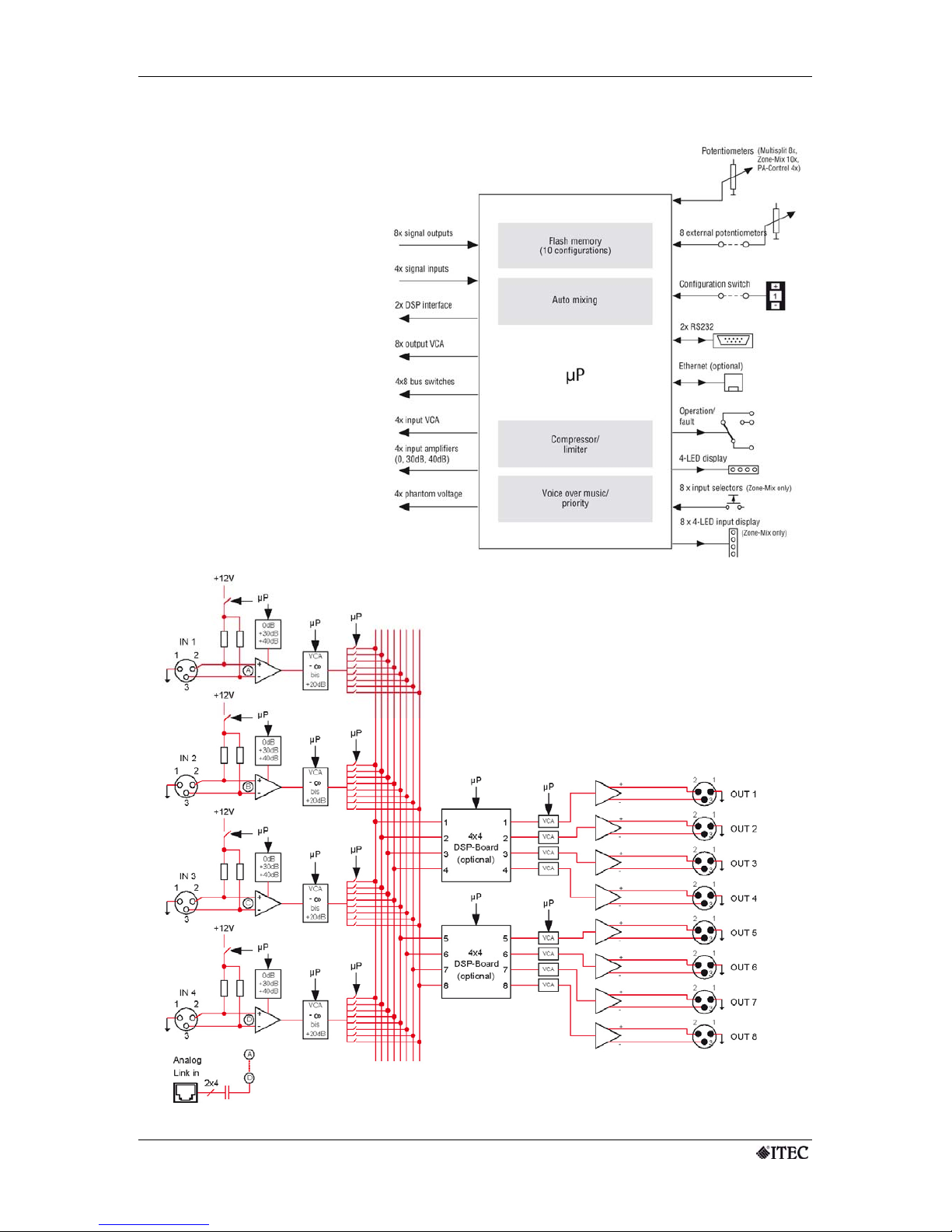
BLOCK DIAGRAM
14
Page 15

MULTISPLIT / PA-CONTROL / ZONE-MIX 4/8 DIGITAL
www.itec-audio.com MULTISPLIT / PA-CONTROL / ZONE-MIX 4/8 DIGITAL
DSP extension (optional)
A version with two built-in 4×4 DSP matrix modules is also available.
The user-friendly configuration functions for the DSP modules are contained in the ITEC-
SplitDesign program. The DSP module works in 24-bit/96 kHz mode and is equipped with
the most suitable algorithms. It contains four 9-band parametric filters with freely adjustable
quality and frequency.
The 4×4 matrix allows the four processed signals to be applied to the four outputs. In
addition, each output features a delay (0.023 to 500 ms) and a bandpass filter (1st to 4th
order).
DSP BLOCK DIAGRAM
15
Page 16

MULTISPLIT / PA-CONTROL / ZONE-MIX 4/8 DIGITAL
www.itec-audio.com MULTISPLIT / PA-CONTROL / ZONE-MIX 4/8 DIGITAL
Technical specifications
GENERAL
Frequency response 20 Hz – 20 kHz/ –3 dB
Harmonic distortion < 0.005 %
Overall dynamics 103 dB (96 dB with DSP module)
POWER SUPPLY External switched-mode power supply unit
Input 115 – 230 V AC
Output +12 V, –12 V, +5/20 W
INPUTS 4 × symmetrical
Max. gain User-definable from –20 dB to +60 dB
Phantom voltage +12 V
Input impedance 6.6 k Ω
OUTPUTS 8 × symmetrical
Max. output level +20 dB (+10 dB with DSP module)
Output impedance Symmetrical 300 Ω, unsymmetrical 150 Ω
DIMENSIONS (w × d × h) mm 482 (431) × 180 × 44 mm; 19” 1 HU
WEIGHT kg 2.40
DSP PLUG-IN MODULE (2 off. possible)
24 bit/96 kHz
4 inputs, 4 outputs
General
4×4 matrix per module
PER INPUT 9-band fully-parametric equalizer ± 15 dB
Medium frequency User-definable from 20 Hz to 20 kHz
Filter quality User-definable from 0.1 to 70
PER OUTPUT Delay: 0.023 – 500 ms/bandpass filter: 1st – 4th order
LAN MODULE
INTERFACE Ethernet 10Base-T or 100 Base-TX (auto-sensing, full/half duplex)
PROTOCOLS TCP/IP, UDP/IP, ARP, ICMP, SNMP, TFTP, Telnet, DHCP, HTTP Internet Web
Server
SPLITDESIGN SOFTWARE
You can download the current version of our software from the following address: http://itec-audio.com/download/splitter/splittersetup.exe
If you have any questions, please contact us at office@itec-audio.com or http://www.itec-audio.com/
ITEC Tontechnik und Industrieelektronik GesmbH,
A-8200 Lassnitzthal 300, Austria, Europe
Tel.: +43 (0)3133 37800, office@itec-audio.com, www.itec-audio.com
16
 Loading...