

Page 1
www.i-tec.com.pt
9
Electronic Door Viewer
USER MANUAL
The following rights are reserved:
• Any changes, without previous notice, made to either the functionality or
appearance of this product will invalidate the guarantee.
• Use of this product in any environment or in any way other than specied
here will also invalidate the guarantee.
• Parameters of digital products might change under different external terms.
Our products are only guaranteed for usage under veried circumstances.
iViewer 03 ECO
Page 2
www.i-tec.com.pt
10
Attention:
1. Please read the instruction manual before use.
2. DO NOT disassemble the camera or the mainbody.
3. Handle with care.
4. DO NOT use any chemicals to clean this product, such as alcohol or
benzene thinner.
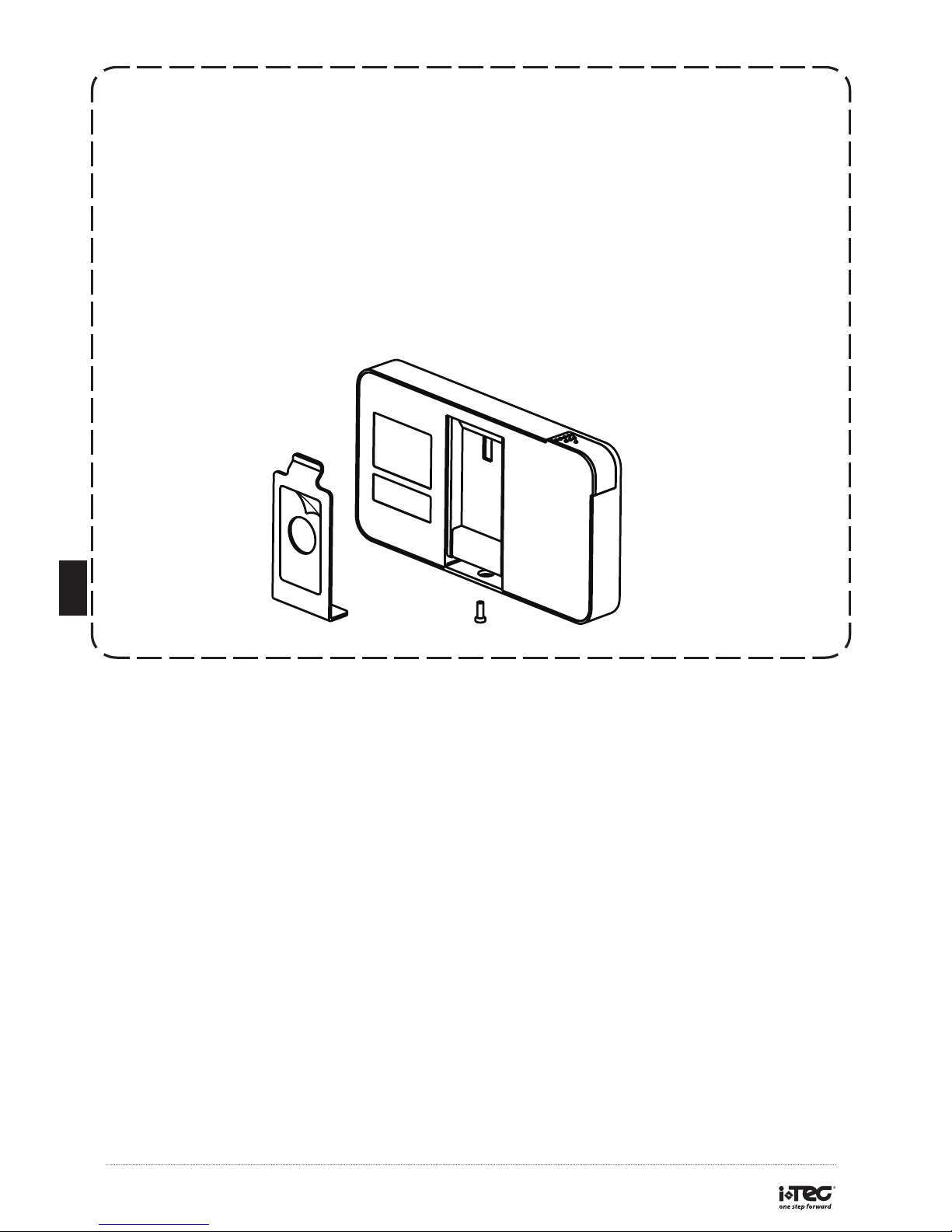
5. Please unscrew from the bottom of the digital door viewer, take out the
holding plate and take off the plastic cover on it and prepare to install.
Battery:
Dispose of used batteries appropriately, DO NOT bury or burn the batteries
and keep them away from children. DO NOT re-charge or disassemble the
batteries.
EN
Page 3
www.i-tec.com.pt
11
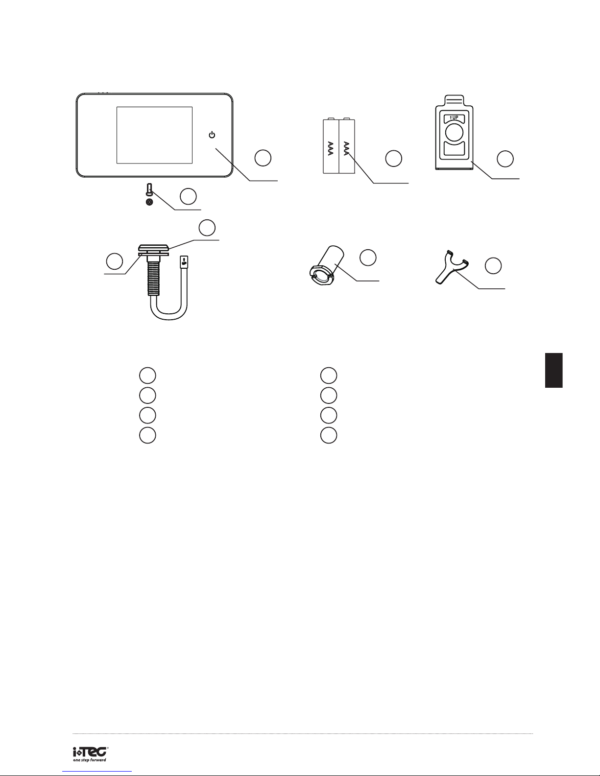
Package list:
2
1
3
4
5
6
7
8
1 2
5 6
8
3 4
7
Digital door viewer
List of contents:
Locking bolt 1 pc
Washer Camera
Tightening tool
2 AAA batteries Holding plate
Locking barrel
A
A
A
A
AA
Before installation:
Prior to mounting the peephole viewer, please make sure you have installed
the batteries included.
EN
Page 4
www.i-tec.com.pt
12
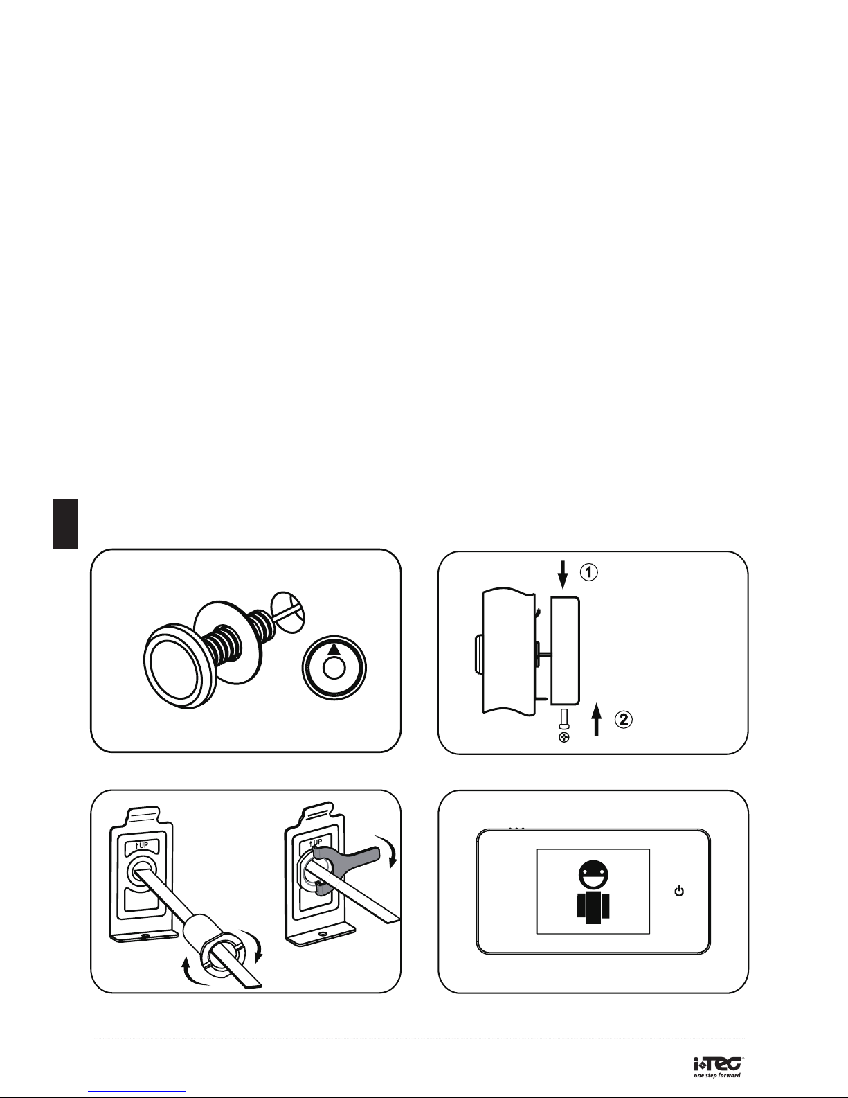
Installation:
1. Replace the existing door viewer or drill a 14mm hole in the door at eye
level. Insert the camera from the outside while inserting the washer between
the back of the lens and the door. Make sure that the arrow mark on front of
the camera points upwards.(FIG. 1)
2. Fit the holding plate over the end of the lens then screw the locking
barrel on to the threaded part of the camera and tighten(a tightening tool is
provided), this will hold the plate to the door.Make sure that the arrow on the
plate points upwards.(FIG. 2)
3. The data wire should be fully plugged in at the back of the screen; excess
wire should be gently placed into the groove at the back of the screen.
4. Hook the digital door viewer over the bracket at the top of the locking plate
and secure the digital door viewer case with the locking bolt.(FIG. 3)
FIG. 1
FIG. 2
FIG. 4
FIG. 3
Hang
Screw
Door
EN
Page 5
www.i-tec.com.pt
13
EN
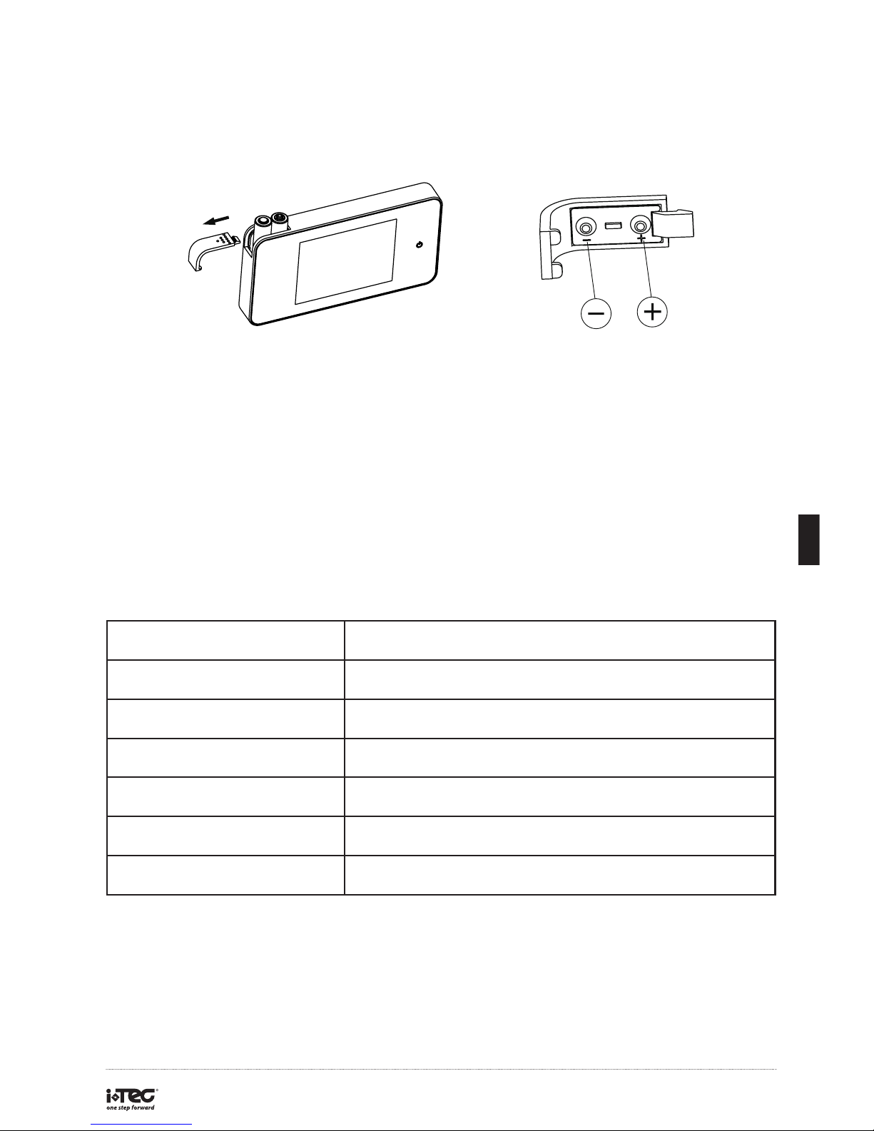
Installation and replacement of the batteries:
1. Slide the cover to the left to open.
2. Install the batteries in accordance with the +/- sign.
3. Reverse this process to close the cover.
Operation:
1. Power Button:
- Touch and release the power button, then the unit will continue working for
the next 10 seconds.
2. Low power indicator:
- When the batteries are running low, a red battery shape indicator will
appear on the screen. Please change batteries when this indicator appears.
Specications:
Door thickness 38~110mm
Door barrel diameter 14-22mm
Camera 3 Megapixels HD Def.
LCD Screen 2.6”TFT
Power 2 AAA batteries
Size 110 (W) x 59(H) x 14(D)mm (4.33”x2.32”x0.55”)
Weight 100g (4.23 oz)
Page 6
www.i-tec.com.pt
14
WARNING
Make sure you assemble the door bell camera carefully.
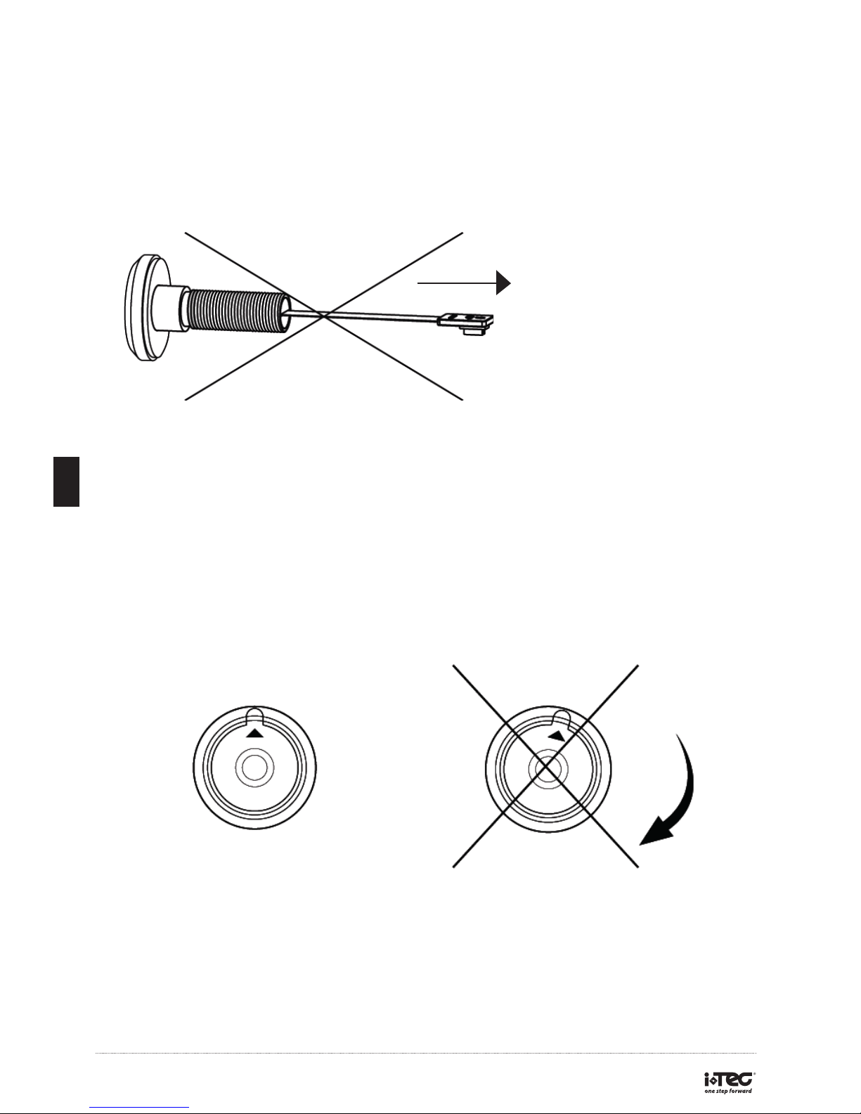
DO NOT pull or fold the camera wire. If the camera wire is pulled or folded,
this could damage the product.
When tting the door viewer camera, rst unscrew the camera barrel and
insert the door viewer camera into the peephole with the arrow points up.
After the camera is well positioned, screw up the locking barrel from inside
door. DO NOT rotate the camera from out side door, this could damage the
camera. Also DO NOT rotate camera when disassembling this product.
* Please do not twist the door viewer
or the monitor after connecting cable.
EN
Pull or fold
the camera wire
Correct Assembly
Do not rotate the out
door camera when
assembling
Incorrect Assembly
Rotate the out door
camera when
assembling
 Loading...