

Page 1
SR-5300/DR-5300/MR-5300
WM-5300/WT-5300/WM-5320/WT-5320/MT-92
PROFESSIONAL RADIO MICROPHONE SYSTEM
IN THE UHF FREQUENCY RANGE
MANUAL
Page 2

2 www.itec-audio.com
MICROPHONES
ITEC 5300 RADIO MICROPHONE SYSTEMS
With the ITEC 5300, you have a modern and professional radio microphone system in the UHF frequency
range. The receivers (the receiver module and the 19“ installation module) are True-Diversity receivers,
guaranteeing a wide range and interference-free reception without temporary cancellations. An innovative
„Pilot Tone“ procedure provides reliable protection against interference caused by external transmitters and
prevents switching clicks during switching on and off of the transmitter.
1. Introduction
1.1. Overview of system components
Transmitter
WM 5300 Hand-held microphone, condenser capsule. Operation with 2 batteries (1.5V / “AA“)
WM 5320 Hand-held microphone, condenser capsule. With a lithium-ion battery (18500)
WT 5300 Pocket transmitter, operation with 2 batteries (1.5V / “AA“)
WT 5320 Pocket transmitter with a lithium-ion battery (18500)
MT 92 Transmitter module for installation in mobile sound systems, 12V DC supply
Receiver
SR 5300 Diversity receiver, 1/2 19“, 1 HE
DR 5300 Diversity double receiver, 1/2 19“, 1 HE
MR 5300 Diversity receiver module for installation in mobile sound systems, 12V DC supply
Accessories
FB 71 Mounting bracket for the installation of an SR 5300 or DR 5300 in a 19“ rack
FB 72 Mounting bracket for the installation of two SR 5300 or DR 5300 in a 19“ rack
HC 80
Double charging station for the charging of two WM 5320, WT 5320 or 18500 battery
1.2. Features of the system
Page 3
www.itec-audio.com 3
MICROPHONES
ITEC 5300 RADIO MICROPHONE SYSTEMS
Installation of a receiver with mounting bracket set FB 71:
Installation of 2 receivers with mounting bracket set FB 72
In case of rack installation, the use of external antennas is recommended
1 m
1 m
1 m
1 m
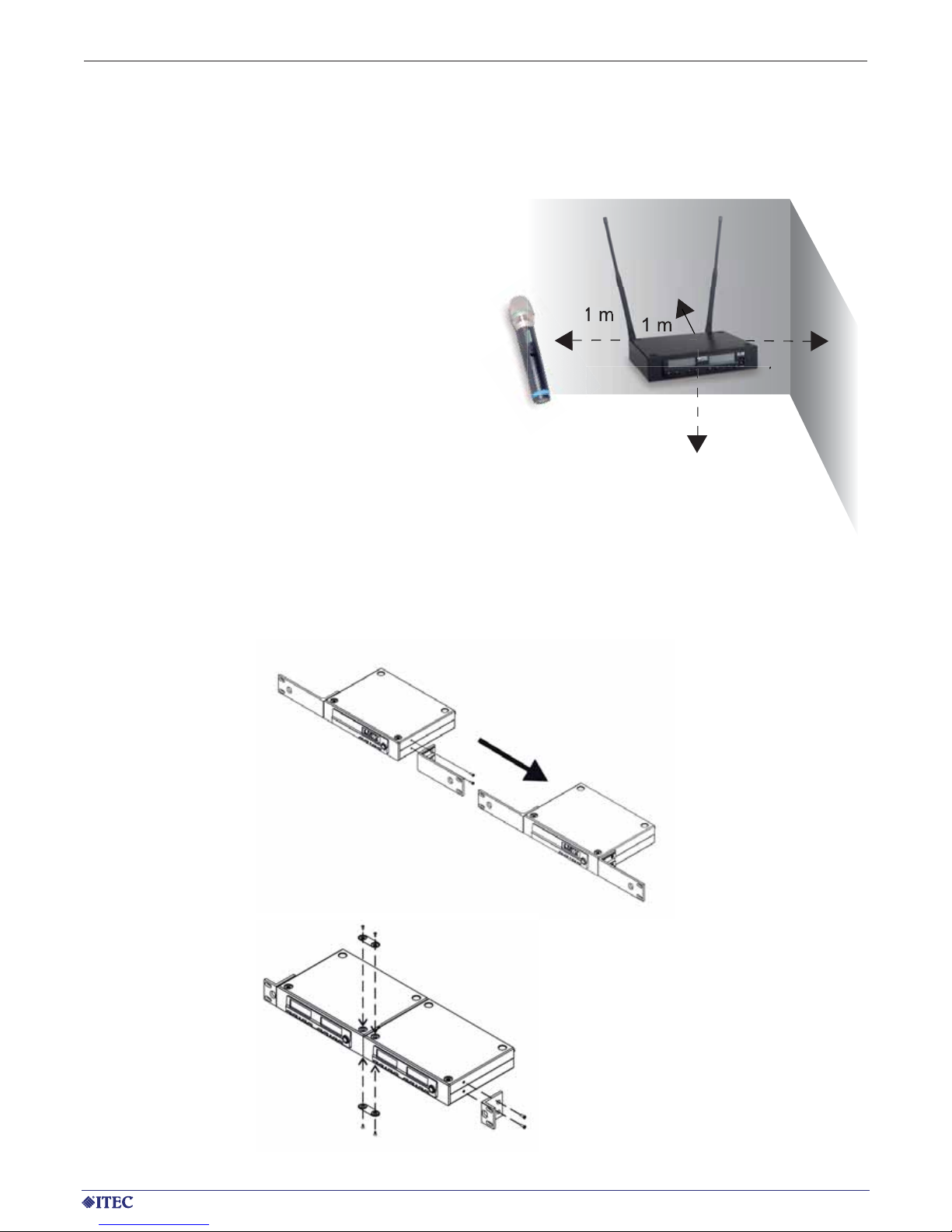
1.3. General assembly instructions
1.3.1. Positioning of the receiver
For proper operation, the receiver should be positioned as high as possible, at least, however,
1 m above the floor. The clearance from walls
and metal surfaces should also be at least 1
m. For proper operation, the transmitter (microphone) must not be positioned closer than 1 m
from the receiver. Proximity to sources of interference, such as e.g.: motors, fluorescent lamps,
spotlights with ballasts, cars, mobile telephones,
computers etc. should also be avoided.
1.3.2. Assembly of the receivers in the 19“ rack
Page 4
4 www.itec-audio.com
MICROPHONES
ITEC 5300 RADIO MICROPHONE SYSTEMS
2. Receiver
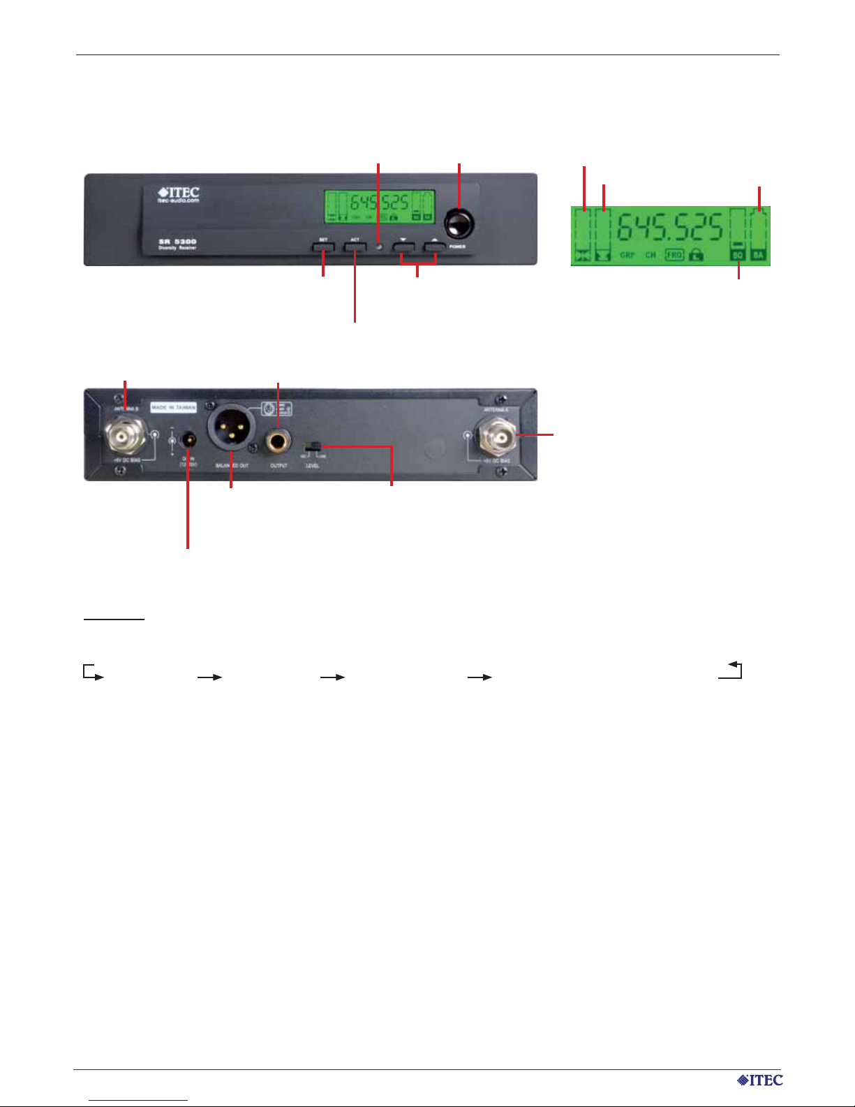
2.1. Diversity receiver ITEC SR-5300
SET
UPDATE
IR DIODE
ARROW KEYS FOR CHANGING
PARAMETERS
MAIN SWITCH ON/OFF
CONNECTION
ANTENNA B
CONNECTION 12V DC
PSU
AUDIO OUTPUT
SYMMETRICAL
MIC LEVEL
AUDIO OUTPUT UNSYMMETRICAL
MIC LEVEL OR LINE LEVEL
MIC/LINE SELECTOR SWITCH FOR
ASYMMETRICAL OUTPUT
CONNECTION
ANTENNA A
Settings:
Pressing the SET button changes the setting mode in the order listed below:
GRP (group) CH (channel) FRQ (frequency) SQ (squelch - noise suppression)
When the corresponding display flashes, the setting can be changed using the arrow keys.
Group and channel: see Appendix List of permanently programmed frequencies
Frequency: free setting of the frequency only possible in group 11!
Squelch: 1 bar (low noise suppression = high range) up to
5 bars (high noise suppression = low range)
If a transmitter is in operation in the environment, its frequency cannot be selected!
Disable/Enable by a long press of the SET button. If the button lock is active, a key symbol appears on the
display.
The frequency setting of the corresponding microphone or pocket transmitter takes place by pressing the
ACT button. For this purpose, the microphone / pocket transmitter must be switched on and the IR receiver
diode of the transmitter must be held at a distance of approximately 10 cm from the IR transmitter diode of
the receiver.
Caution: No other microphones in the vicinity may be switched on during the updating procedure. They may
otherwise accidentally receive the IR data.
HF LEVEL
LF LEVEL
SQUELCH
BATTERY STATUS
OF TRANSMITTER
Page 5

www.itec-audio.com 5
MICROPHONES
ITEC 5300 RADIO MICROPHONE SYSTEMS
ARROW KEYS
FOR CHANGING
PARAMETERS
2.2. Diversity receiver ITEC DR-5300
SET
UPDATE
IR DIODE
ARROW KEYS
FOR CHANGING
PARAMETERS
MAIN SWITCH ON/OFF
CONNECTION
ANTENNA B
CONNECTION 12V DC
PSU
AUDIO OUTPUT
SYMMETRICAL
MIC LEVEL
(MIXED OUT)
AUDIO OUTPUT B ASYMMETRICAL
MIC OR LINE LEVEL MIXED OUT
MIXED/SEPERATE
SELECTOR SWITCH
CONNECTION
ANTENNA A
SET
UPDATE
IR DIODE
MIC/LINE SELECTOR SWITCH
FOR ASYMMETRICAL OUTPUT
AUDIO OUTPUT B SYMMETRICAL
AUDIO OUTPUT A
ASYMMETRICAL MIC LEVEL
Settings:
Pressing the SET button changes the setting mode in the order listed below:
GRP (group) CH (channel) FRQ (frequency) SQ (squelch - noise suppression)
When the corresponding display flashes, the setting can be changed using the arrow keys.
Group and channel: see Appendix List of permanently programmed frequencies
Frequency: free setting of the frequency only possible in group 11!
Squelch: 1 bar (low noise suppression = high range) up to
5 bars (high noise suppression = low range)
If a transmitter is in operation in the environment, its frequency cannot be selected!
Disable/Enable by a long press of the SET button. If the button lock is active, a key symbol appears on the
display.
The frequency setting of the corresponding microphone or pocket transmitter takes place by pressing the
ACT button. For this purpose, the microphone / pocket transmitter must be switched on and the IR receiver
diode of the transmitter must be held at a distance of approximately 10 cm from the IR transmitter diode of
the receiver.
Caution: No other microphones in the vicinity may be switched on during the updating procedure. They may
otherwise accidentally receive the IR data.
Page 6

6 www.itec-audio.com
MICROPHONES
ITEC 5300 RADIO MICROPHONE SYSTEMS
3. Hand-held microphones
3.1 ITEC WM-5300
DISPLAY GROUP, CHANNEL AND BATTERY
IR DIODE (REAR)
LED BATTERY STATUS INDICATOR
ON/OFF SWITCH
POWER LOCK
3.1.2 Batteries
The WM-5300 is operated with 2 AA batteries. Please make sure that both batteries are always replaced by
new ones of the same type. When inserting the batteries, please pay attention to correct polarity . The status
of the battery is shown on the LCD display. The red LED battery status display also indicates the battery
status: when switching on, the display lights up for approximately 1 second and then goes out again. If this
indicator lights up permanently, this is a warning that signalises the low charging status of the battery.
3.1.1 Replacement of the capsule
The capsule can be unscrewed for replacement. The microphone is equipped with an electret capsule as
standard. A dynamic capsule is available upon request.
Battery change:
Unscrew the cap at the bottom end of the microphone and insert two new
batteries. Ensure correct polarity (minus pole resp. at the spring contact,
top and bottom)! Battery type: 2x Mignon “AA” 1.5V
Note: Old batteries are special waste and must be disposed of accordingly.
Some batteries (mainly cheap products) may leak in case of longer storage, which may lead to corrosion and destruction of the battery contacts.
Use high-quality alkaline batteries from brand manufacturers; these also
have a longer service life.
Page 7

www.itec-audio.com 7
MICROPHONES
ITEC 5300 RADIO MICROPHONE SYSTEMS
3.2 ITEC WM-5320, rechargeable
IR DIODE (REAR)
LED BATTERY INDICATOR
GREEN = BATTERY OK
YELLOW = BATTERY WEAK
ON/OFF SWITCH
POWER LOCK
PULL OFF CAP, TURN BY 180°
AND PUT CAP BACK ON AGAIN
3.2.1 Replacement of the capsule
The capsule can be unscrewed for replacement. The microphone is equipped with an electret capsule as
standard. A dynamic capsule is available upon request.
3.2.2 Lithium ion battery
The WM 5320 has a lithium ion battery of type 18500. When charging, only use the original ITEC-HC 80 charger. The external charging contacts enable charging by simply placing the microphone into the charging
station without having to remove the battery. However, changing the battery and charging the removed battery are also possible (keep a spare battery for long periods of use). The operating time with a fully charged
battery is approx. 10 – 12 hours.
Replacing the lithium ion battery:
Unscrew the microphone capsule. Remove the round contact plate by pressing the two catches. The lithium
ion battery can now be easily removed. Pay attention to correct polarity when inserting the replacement
battery. The plus pole (marked by a groove) is at the top.
Page 8

8 www.itec-audio.com
MICROPHONES
ITEC 5300 RADIO MICROPHONE SYSTEMS
4. Pocket transmitter
4.1. ITEC WT-5300
HEADSET CONECTOR, LAVALIER MICROPHONE ETC.
MUTE BUTTON
DISPLAY:
GROUP, CHANNEL AND BATTERY
BATTERY COMPARTMENT
TRANSMISSION
ANTENNA
SET BUTTON
MODE BUTTON
IR DIODE
ON/OFF BUTTON
4.1.1 Settings
The current settings are displayed by pressing the MODE button. To change a value, the SET button must
be pressed for 10 seconds. When the display flashes, the value can be changed by pressing the SET button
again.
Display/selection option Note
GRP CH XX XX
Display only - Change by IR signal from the receiver
FREQ XXX.XXX MHz
Display only - Change by IR signal from the receiver
AF-GAIN -18 -12 -6 0 +6 +12 Amplification -18dB (line) to +12dB (microphone level)
RF-Power LOW HI Setting the transmission power
MUTE
MODE
Disable Manual
Activated (manual) or deactivated (disable) the MUTE
button on the device
SET LOCK Unlock Lock
Locking of the button function including the On/Off
button (power lock)
4.1.2 Battery change
Open pocket transmitter cover by pressing left and right snapper
simultaneously. Insert two new batteries. Note the poles (minus
pole at spring contact, left)! Battery type: 2 „AA“ 1.5V Mignon
Battery status on display.
Page 9

www.itec-audio.com 9
MICROPHONES
ITEC 5300 RADIO MICROPHONE SYSTEMS
4.2. ITEC WT-5320
HEADSET CONECTOR, LAVALIER MICROPHONE ETC.
MUTE BUTTON
DISPLAY:
GROUP, CHANNEL AND BATTERY
BATTERY COMPARTMENT
TRANSMISSION
ANTENNA
SET BUTTON
MODE BUTTON
IR DIODE
ON/OFF BUTTON
4.2.1 Settings
The current settings are displayed by pressing the MODE button. To change a value, the SET button must
be pressed for 10 seconds. When the display flashes, the value can be changed by pressing the SET button
again.
Display/selection option Note
GRP CH XX XX
Display only - Change by IR signal from the receiver
FREQ XXX.XXX MHz
Display only - Change by IR signal from the receiver
AF-GAIN -18 -12 -6 0 +6 +12 Amplification -18dB (line) to +12dB (microphone level)
RF-Power LOW HI Setting the transmission power
MUTE
MODE
Disable Manual
Activated (manual) or deactivated (disable) the MUTE
button on the device
SET LOCK Unlock Lock
Locking of the button function including the On/Off
button (power lock)
4.2.2 Charging and replacing the lithium ion battery
When charging, only use the original ITEC-HC 80 charger. The external
charging contacts enable charging by simply placing the pocket transmitter
into the charging station without having to remove the battery . However, changing the battery and charging the removed battery are also possible (keep a
spare battery for long periods of use). The operating time with a fully charged
battery is approx. 10 – 12 hours.
Open the cover on the pocket transmitter to replace the battery. For this purpose, simultaneously press the catches on the left and right-hand side. Insert
the replacement battery . Note the poles (plus pole, marked by a groove, is on
the right)! The type of battery is 18500.
Page 10

10 www.itec-audio.com
MICROPHONES
ITEC 5300 RADIO MICROPHONE SYSTEMS
5. Installation modules
5.1. Receiver module ITEC MR 5300
Channel settings:
Press the SCAN button for 2 seconds: 7-segment display flashes. Briefly pressing again switches over
to the next channel.
Keep the SCAN button pressed: Channelling takes place at one-second intervals
If a transmitter is in operation in the environment, its frequency cannot be selected!
The frequency setting of the corresponding microphone or pocket transmitter takes place by pressing the
ACT-button. For this purpose, the microphone / pocket transmitter must be switched on and the IR receiver
diode of the transmitter must be held at a distance of approximately 10 cm from the IR transmitter diode of
the receiver.
Caution: No other microphones in the vicinity may be switched on during the updating procedure. They
may otherwise accidentally receive the IR data.
Noise suppression (squelch):
Setting takes place via a potentiometer on the front panel (sensitivity).
Turning in counter-clockwise direction ( - ): high noise suppression = low range
Turning in clockwise direction ( + ): low noise suppression = high range
Pin assignment (underside)
CHANNEL INDICATOR RECEPTION INDICATOR
LEVEL INDICATOR
ON/OFF BUTTON
VOLUME CONTROL
NOISE SUPPRESSSION
(SQUELCH)
IR DIODE
UPDATE
SET
GND
ANTENNA B
+12V
GND
SIGNAL GND
SIGNAL OUTPUT
ANTENNA A
GND
Page 11

www.itec-audio.com 11
MICROPHONES
ITEC 5300 RADIO MICROPHONE SYSTEMS
5.2. Transmitter module ITEC MT 92
CHANNEL INDICATOR
LIMIT INDICATOR
(AUDIO SIGNAL TOO LARGE)
CHANNEL SELECTOR
SWITCH
The module transmitter MT 92 cannot be updated via IR. Channel selection takes place manually by
pressing the CH button The transmitter can be switched on and off by a long press of the CH button.
Pin assignment (top side)
+12V
GND
SIGNAL GND
SIGNAL INPUT
MUTE (MUST BE ON +12V TO BE ACTIVE)
ANTENNA
ANTENNAS GND
Page 12

12 www.itec-audio.com
MICROPHONES
ITEC 5300 RADIO MICROPHONE SYSTEMS
6. The charging station HC 80
Using the charging station HC 80, not only hand-held microphones of type WM 5300, pocket transmitters of
type WT 5300 can be individually charged, but also lithium-ion batteries of type 18500. A total of two of these
units – in any combination - can be charged at the same time.
LED RED = CHARGING
LED GREEN = FULLY CHARGED
POWER LED
LED RED = CHARGING
LED GREEN = FULLY CHARGED
Simultaneous charging of 2 transmitters WM
5300 or WT 5300 possible
SPARE BATTERY
COMPARTMENT
CHARGING OF A
REMOVED BATTERY
Page 13

www.itec-audio.com 13
MICROPHONES
ITEC 5300 RADIO MICROPHONE SYSTEMS
Page 14

CH
SR 5300
DR 5300
Gruppe
CH
MR 5300
12345678910 11
1 645.275 645.525 645.775 646.025 664.100 645.675 664.950 664.425 644.200 645.525 1
2 646.075 646.325 646.575 646.825 645.700 647.175 645.800 644.925 644.700 646.050 2
3 652.400 652.650 652.900 653.150 651.100 651.175 646.300 645.675 645.450 647.025 3
4 657.225 657.475 657.725 657.975 653.200 654.675 647.050 646.175 645.950 647.450 4
5 660.800 661.050 661.300 661.550 659.600 657.675 648.050 647.675 647.450 650.150 5
6 663.125 663.375 663.625 663.875 663.300 662.675 648.650 648.275 648.050 650.675 6
7 664.900 665.150 665.400 665.650 664.400 664.675 650.650 650.000 649.775 651.725 7
8 666.125 666.375 666.625 666.875 667.600 667.175 655.750 651.350 651.125 652.175 8
9 658.250 659.625 659.400 659.675 9
10 658.950 660.450 660.225 660.100 0
11 661.725 661.025 660.800 661.275 A
12 662.400 661.850 661.625 661.825 B
13 664.950 663.600 663.375 664.400 C
14 665.450 664.525 664.300 664.925 D
15 666.300 665.100 664.875 666.050 E
16 666.800 665.925 665.700 666.475 F
Free frequency selection
Group 10 of receivers SR 5300 and DR 5300 is compatible with the channels of the MR 5300.
Standard frequencies (6B)
other frequency bands upon request.
14 www.itec-audio.com
MIKROFONE
ITEC 5300 RADIO MICROPHONE SYSTEMS - FREQUENCY LIST
7. Appendix: Frequency list
Page 15

www.itec-audio.com 15
MICROPHONES
ITEC 5300 RADIO MICROPHONE SYSTEMS
Page 16

GENERAL FEATURES OF THE SYSTEM
Maximum Frequency Deviation ± 40 kHz
Frequency Response 50 Hz – 18 kHz
Harmonic Distortion < 0.5% @ 1 kHz
Signal-to-Noise Ratio > 106 dB
WM 5300 HAND-HELD MICROPHONE
Power supply
2 batteries, alkaline “AA“ 1.5 V
Operating time
approx. 20 hours with one set of batteries
Dimensions, weight L=225 mm, diam.=50 mm, Weight=260 g
WM 5320 HAND-HELD MICROPHONE, BATTERY OPERATION
Power supply
1 lithium-ion battery, type 18500, 3.7 V
Operating time
approx. 10 - 12 hours with one battery charge
Dimensions, weight L=250 mm, diam.=50 mm, Weight=285 g
WT 5300 POCKET TRANSMITTER
Power supply
2 batteries, alkaline “AA“ 1.5 V
Operating time
approx. 10 - 12 hours with one battery charge
Dimensions, weight 85 x 65 x 22 mm, Weight=90 g
WT 5320 POCKET TRANSMITTER, BATTERY OPERATION
Power supply
1 lithium-ion battery, type 18500, 3.7 V
Operating time
approx. 10 - 12 hours with one battery charge
Dimensions, weight 75 x 65 x 22 mm, Weight=110 g
SR 5300 DIVERSITY RECEIVER, ½ 19“
Power supply 12 V DC (PSU 230 V AC / 12 V DC included)
Dimensions, weight 210 x 44 x 180 mm, (1/2 19“, 1 HE), Weight=0.8 kg
DR 5300 DIVERSITY DOUBLE RECEIVER, ½ 19“, ½ 19“
Power supply 12 V DC (PSU 230 V AC / 12 V DC included)
Dimensions, weight 210 x 44 x 180 mm, (1/2 19“, 1 HE), Weight=0,95 kg
MR 5300 RECEIVER MODULE
Power supply 12 V DC , power consumption approx. 220 mA
Dimensions, weight 75 x 35 x 145 mm (W x H x D), Weight=140 g
MT 5300 TRANSMITTER MODULE
Power supply 12 V DC , power consumption approx. 150 mA
Dimensions, weight 65 x 35 x 165 mm (W x H x D), Weight=80 g
HC 80 CHARGING STATION
Power supply 12 V DC (PSU 230 V AC / 12 V DC included)
Dimensions, weight 90 x 80 x 150 mm (W x H x D), Weight=320 g
ITEC- Tontechnik und Industrieelektronik GesmbH, A-8200 Lassnitzthal 300 / Austria / Europe
Tel.: +43 (0)3133 / 3780-0, office@itec-audio.com, www.itec-audio.com
16 www.itec-audio.com
MICROPHONE
ITEC 5300 RADIO MICROPHONE SYSTEMS - SPECIFICATIONS
 Loading...