

Page 1

Intelligently HD Mixer Insertion
Matrix
User Manual
TS-9208H
TS-9216H
TS-9232H
Before using the system, please read this manual first
Page 2

1
1. Important safety notes and attention points
◆ This machine can be used under AC~110-240V,50/60Hz
◆ In order to decrease the risk of fire and electrical shock, please do not use the machine
under rain or moisture condition.
◆ Don't place the line detector in direct sunlight or near the heat source.
◆ Do not dismantle the line detector shell, and touching the chassis parts may result in
electric shock and damage within the circuit detector, such machine maintenance and
adjustment, please contact the designated dealers.
◆ Line detector internal components are informal touched may be brought severe
electric shock accidents and damage line inspection Sensors, the company is not
responsible for this.
◆ When found abnormal smell or smoke, please immediately cut off the power and
unplug the power plug, stop use and ask for professional help.
◆ With line detector microprocessor, pls do not switch machine open or close very fast.
◆ If you have any question, please contact the dealer as soon as possible.
Page 3

2
2. Function Introduction
◆ TS-9208H/TS-9216H/TS-9232H Professional mixed cross point matrix switcher is a flexible
configuration matrix switcher for signals. Using high-performance hardware design, which
perfectly support all kinds of high-definition digital/analog signal switching process, and
support two-way RS-232, distribution of IR signal switching function. It can used for many of
the video industry and the switch control signal processing one-stop solution, can be widely
used in radio and television engineering, multimedia conference room, large screen display,
television teaching, command and control center and other places.
◆ TS-9208H/TS-9216H/TS-9232H mixed matrix switcher provide HDMI, DVI, VGA, CVBS,
S-Video, YPbPr local direct input signal, as well as the HDMI, DVI direct output. In addition,
also provide twisted-pair cable input/output interface card. Cooperate with the twisted-pair
transmitter can be extended by the input and output signal through twisted-pair transmission
distance up to 100m, And also provide Fiber input/output interface card which with optical
fiber transmission through a single core multimode optical fiber can extend the input and
output signal transmission distance up to 300 m. What’s more, it can be replaced for the use
of single mode optical fiber transmission of single-mode transceiver transmission to improve
the distance to 20 km. Advanced digital signal processing technology can guarantee the
undistorted signal processing and the best quality images to be sent to the display terminal.
◆ Through custom configuration of the same or different input/output card can be composed
of a single interface type matrix of one or more interface types, such as optical fiber matrix,
the matrix HDMI, DVI matrix, CAT5 matrix, VGA matrix, YUV matrix, S-Video matrix, Video
matrix, and so on.
◆ Mixed matrix switcher offers a variety of control mode, with the crystal key panel operation,
also provide 2 standard RS-232 communication interface and network port, convenient user
used with all kinds of remote control equipment.
Page 4

3
3. The product equipment
TS-9208H/TS-9216H/TS-9232H mixed matrix, may be consist of the following arbitrary
input/output interface card:
◆ Input Card
TS-9208HR input board (8-Channel HDMI Signal Input Card)
TS-9208DR input board (8-Channel DVI Signal Input Card)
TS-9208CR input board (8-Channel Component Video Input Card)
TS-9208SR input board (8-Channel SDI Input Card)
TS-9208GR input board (8-Channel Optical Input Card)
TS-9208TR input board (8-Channel HD BaseT Input Card)
◆ Output the board
TS-9208HC output board (8-Channel HDMI Output Signal Card)
TS-9208DC output board (8-Channel DVI Signal Output Card)
TS-9208CC output board (8-Channel Component Video Output Card)
TS-9208SC output board (8-Channel SDI Output Card)
TS-9208GC output board (8-Channel Optical Output Card)
TS-9208TC output board (8-Channel HD BaseT Output Card)
◆ Optional accessories
Low blank card (file)
Low power supply box (redundant power box)
4. Product feature
◆
support COMP (component Video input interface can transfer the following signal VGA,
CVBS, S-Video, YPbPr), HDMI, DVI, twisted pair (cable will), Fiber (optical Fiber) in
any of the interface card input.
◆
support, DVI, HDMI, twisted pair (cable will), Fiber (optical Fiber) any of the card
output.
◆
support input EDID read, custom functions.
◆ support embedded bidirectional infrared and RS-232 control signal switching
functions (twisted-pair cable or fiber boards and the corresponding transmission).
◆
support is fast channel and embedded control switch signal separation model.
Page 5
4
5. Crate Specifications
Model 8-channel 16-channel 32-channel 72-channel
Height 3U 5U 9U 16U
Effective card number
(a/Taiwan)
Input card 1 2 4 9
Output card 1 2 4 9
Input signal
(maximum way)
TS-9208HR 8 16 32 72
TS-9208DR 8 16 32 72
TS-9208CR 8 16 32 72
TS-9208SR 8 16 32 72
TS-9208GR 8 16 32 72
TS-9208TR 8 16 32 72
Output signal
(maximum way)
TS-9208HC 8 16 32 72
TS-9208DC 8 16 32 72
TS-9208CC 8 16 32 72
TS-9208SC 8 16 32 72
TS-9208GC 8 16 32 72
TS-9208TC 8 16 32 72
6. Nomenclature and functions
6.1 Front Panel
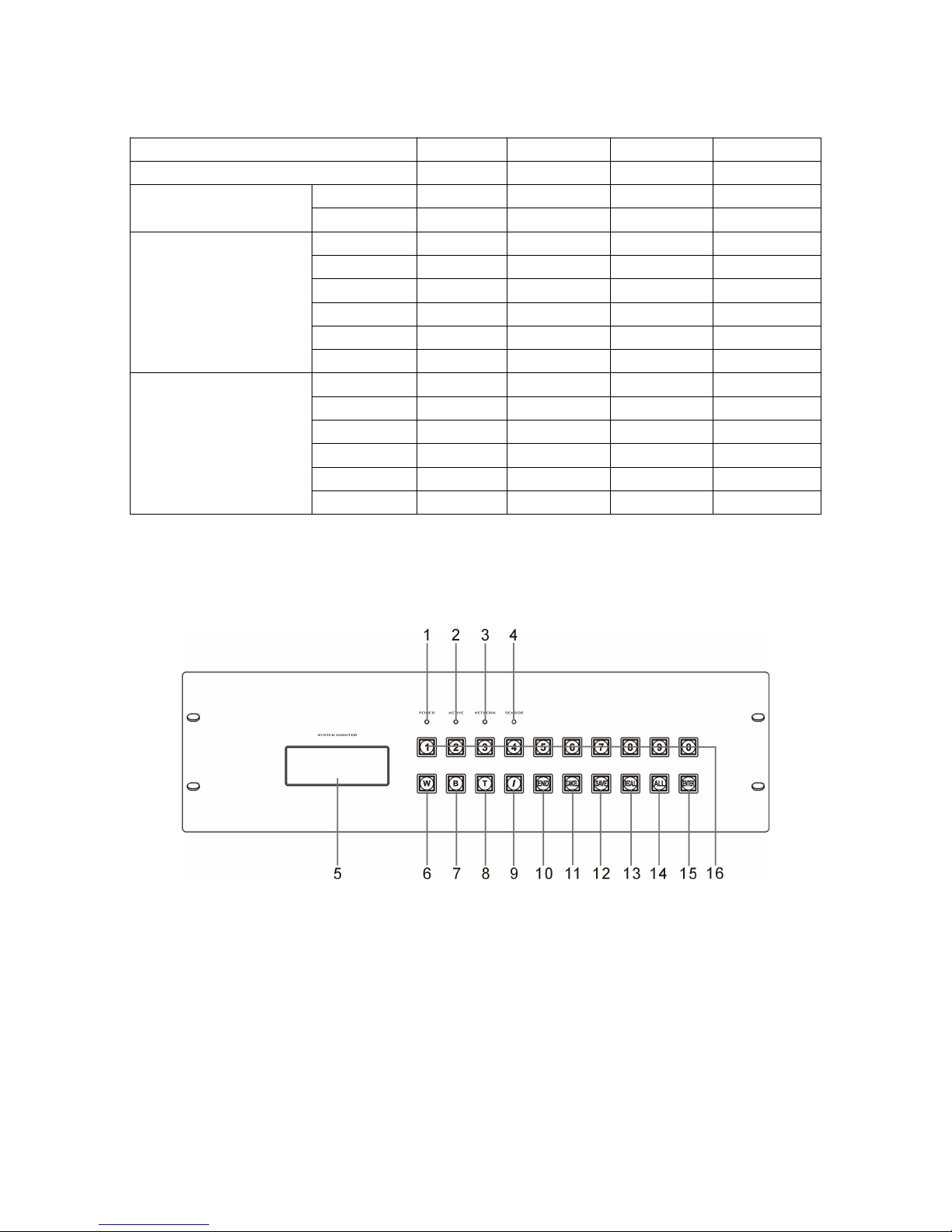
◆ TS-9208H (8 channels )
1) Power indicator light.
2) Instruction execution light.
3) A serial port to accept data light.
4) Infrared Receiver.
5) Screen.
6) Function key for switch AV / infrared/serial port at the same time. It can switch
AV/infrared/serial port from one Channel to other output channels.
Page 6

5
eg: Press “1”, “W”,”3”,”END”,”ENTER”key one after another to switch AV/Infrared/serial port
on the first channel to the third output channel.
7) Switch-optioned key for AV. It can switch AV signal from one channel to other output
channels.
eg: Press “3” “B” “1” “0” “END””ENTER” key to switch AV signal on the third channel to the
tenth output channel.
8) Switch-option key for infrared /serial port at the same time, Which can switch
infrared/serial port data from one channel to other output channels.
eg: Press “2” “T” “8” “END” “ENTER” key to switch infrared, serial port data on the second
channel to the eighth output channel.
9) Command-space key. It can separate output channel port when the output is not
single channel.
eg: Press “1” “B” “2” “/” “1” “/” “3” ,”END” “ENTER” key to switch the first output channel to
the second ,the first and the third output channel.
10) Key for command completion. It is used to end channel option indicator.
11) Cancel key.
eg. Press “1” “B” “2” “END” key one after another, then press “CANCEL” key. Current input
instruction will be can celled, Re-enter instruction can be acceptable.
12) Save key. Corresponding relation of current input and output information can be saved.
eg: Press “SAVE” key firstly, Then press”2”key to save current input and output status.
13) Invoking key, invoke corresponding relation of saved input and output.
eg: Press “Recall” key firstly to invoke saved input and output status in advance and to switch
it.
14) Shortcut key, optional key for one input channel and all output channel: Function key for
direct connection and turn-off function. Shortcut key would not need to use with “END”
“ENTER” key.
eg 1 : Press “7”.”ALL” on after another means switch AV signal in the seventh channel to all
output channels.
eg 2 :Press button ”ALL” firstly , Then press button “1” is direct connection, which means AV
signal in all input channels will be transmitted to all corresponding output channels. That is
Page 7
6
the first input channel switch to the first output channel, the second input channel switch to
the second output channel, the third input channel switch to the third output channel, etc.
eg 3: Press “ALL” firstly, Then press “2” is turn-off function, which means turn off all the
output channels.
15) Command key. Ensure switch option and execute switch.
16) “0,1 …8,9”: Option Key for input and output channel. Can be used for set output and input
channel of AV signal or used for opt for invoking status key or save key.
6.2 Real Panel
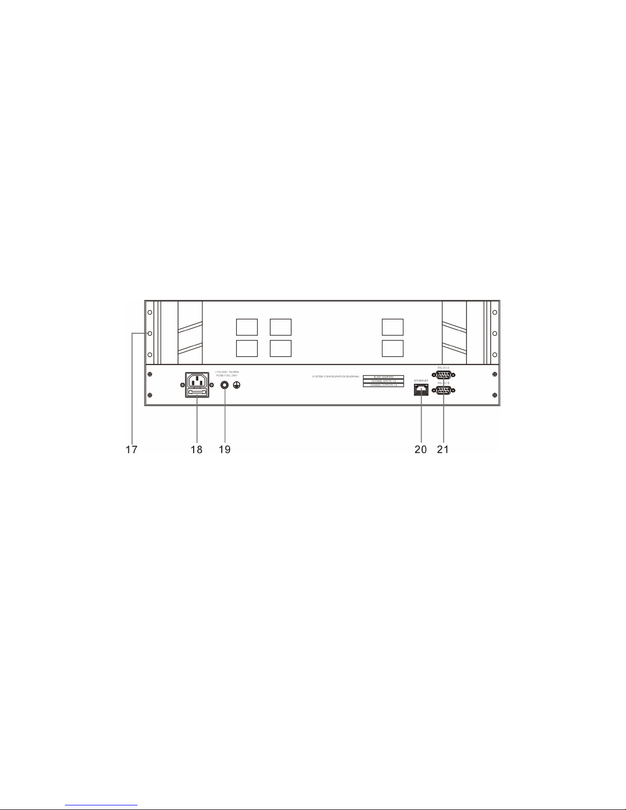
◆ TS-9208H (8 channels)
17) Slot for output panel and input panel.
18) AC ~110-220V 50-60Hz power input.
19) Ground point.
20) Ethernet Interface (RJ45 main interface).
21) Serial Control Interface.
Page 8
7
6.3 Front Panel
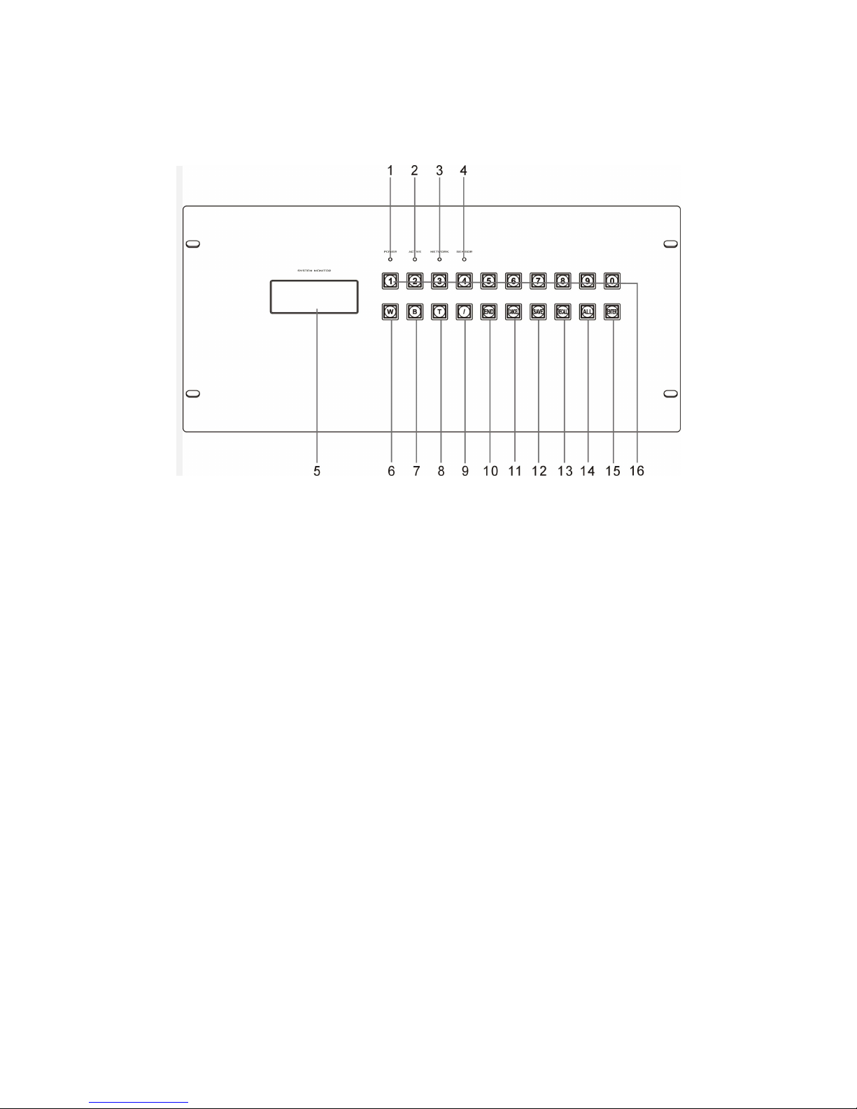
◆ TS-9216H (16 channels)
1) Power indicator light.
2) Instruction execution light.
3) A serial port to accept data light.
4) Infrared Receiver.
5) Screen.
6) Function key for switch AV / infrared/serial port at the same time. It can switch
AV/infrared/serial port from one Channel to other output channels.
eg: Press “1”, “W”,”3”,”END”,”ENTER”key one after another to switch AV/Infrared/serial port
on the first channel to the third output channel.
7) Switch-optioned key for AV. It can switch AV signal from one channel to other output
channels.
eg: Press “3” “B” “1” “0” “END””ENTER” key to switch AV signal on the third channel to the
tenth output channel.
8) Switch-option key for infrared /serial port at the same time, Which can switch
infrared/serial port data from one channel to other output channels.
eg: Press “2” “T” “8” “END” “ENTER” key to switch infrared, serial port data on the second
channel to the eighth output channel.
Page 9

8
9) Command-space key. It can separate output channel port when the output is not
single channel.
eg: Press “1” “B” “2” “/” “1” “/” “3” ,”END” “ENTER” key to switch the first output channel to
the second ,the first and the third output channel.
10) Key for command completion. It is used to end channel option indicator.
11) Cancel key.
eg. Press “1” “B” “2” “END” key one after another, then press “CANCEL” key. Current input
instruction will be can celled, Re-enter instruction can be acceptable.
12) Save key. Corresponding relation of current input and output information can be saved.
eg: Press “SAVE” key firstly, Then press”2”key to save current input and output status.
13) Invoking key, invoke corresponding relation of saved input and output.
eg: Press “Recall” key firstly to invoke saved input and output status in advance and to switch
it.
14) Shortcut key, optional key for one input channel and all output channel: Function key for
direct connection and turn-off function. Shortcut key would not need to use with “END”
“ENTER” key.
eg 1 : Press “7”.”ALL” on after another means switch AV signal in the seventh channel to all
output channels.
eg 2 :Press button ”ALL” firstly , Then press button “1” is direct connection, which means AV
signal in all input channels will be transmitted to all corresponding output channels. That is
the first input channel switch to the first output channel, the second input channel switch to
the second output channel, the third input channel switch to the third output channel, etc.
eg 3: Press “ALL” firstly, Then press “2” is turn-off function, which means turn off all the
output channels.
15) Command key. Ensure switch option and execute switch.
16) “0,1 …8,9”: Option Key for input and output channel. Can be used for set output and input
channel of AV signal or used for opt for invoking status key or save key.
Page 10
9
6.4 Real Panel
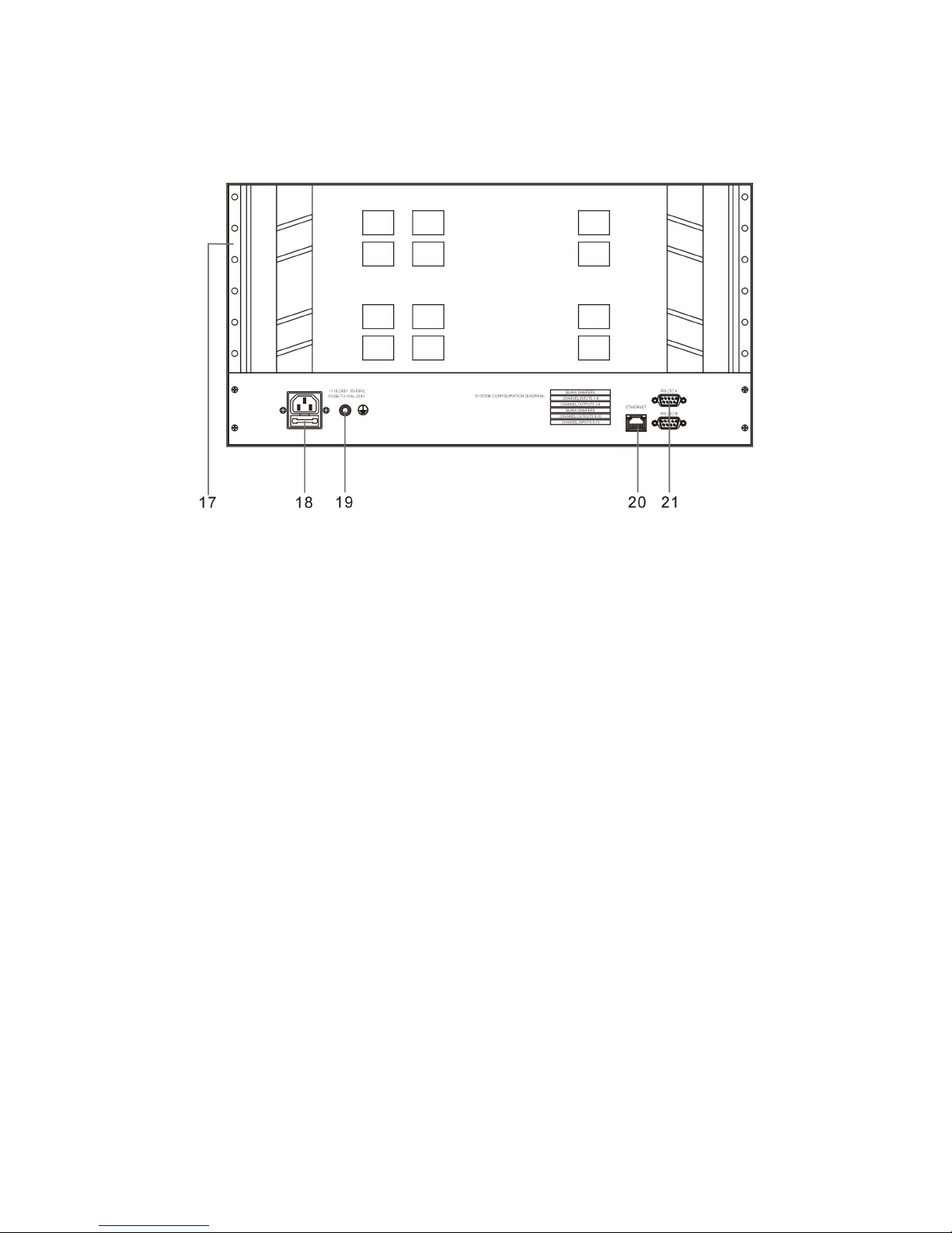
◆ TS-9216H (16 channels)
17) Slot for output panel and input panel.
18) AC ~110-220V 50-60Hz power input.
19) Ground point.
20) Ethernet Interface (RJ-45main interface).
21) Serial Control Interface.
Page 11
10
6.5 Front Panel
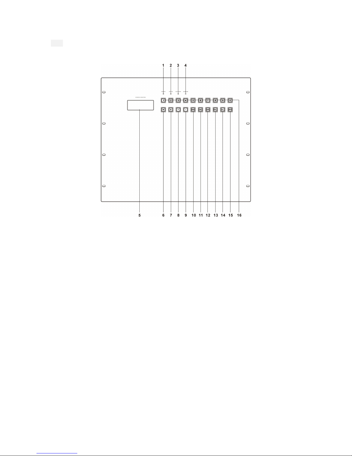
◆ TS-9232H (32 channels)
1) Power indicator light.
2) Instruction execution light.
3) A serial port to accept data light.
4) Infrared Receiver.
5) Screen.
6) Function key for switch AV / infrared/serial port at the same time. It can switch
AV/infrared/serial port from one Channel to other output channels.
eg: Press “1”, “W”,”3”,”END”,”ENTER”key one after another to switch AV/Infrared/serial port
on the first channel to the third output channel.
7) Switch-optioned key for AV. It can switch AV signal from one channel to other output
channels.
eg: Press “3” “B” “1” “0” “END””ENTER” key to switch AV signal on the third channel to the
tenth output channel.
8) Switch-option key for infrared /serial port at the same time, Which can switch
infrared/serial port data from one channel to other output channels.
Page 12

11
eg: Press “2” “T” “8” “END” “ENTER” key to switch infrared, serial port data on the second
channel to the eighth output channel.
9) Command-space key. It can separate output channel port when the output is not
single channel.
eg: Press “1” “B” “2” “/” “1” “/” “3” ,”END” “ENTER” key to switch the first output channel to
the second ,the first and the third output channel.
10) Key for command completion. It is used to end channel option indicator.
11) Cancel key.
eg. Press “1” “B” “2” “END” key one after another, then press “CANCEL” key. Current input
instruction will be can celled, Re-enter instruction can be acceptable.
12) Save key. Corresponding relation of current input and output information can be saved.
eg: Press “SAVE” key firstly, Then press”2”key to save current input and output status.
13) Invoking key, invoke corresponding relation of saved input and output.
eg: Press “Recall” key firstly to invoke saved input and output status in advance and to switch
it.
14) Shortcut key, optional key for one input channel and all output channel: Function key for
direct connection and turn-off function. Shortcut key would not need to use with “END”
“ENTER” key.
eg 1 : Press “7”.”ALL” on after another means switch AV signal in the seventh channel to all
output channels.
eg 2 :Press button ”ALL” firstly , Then press button “1” is direct connection, which means AV
signal in all input channels will be transmitted to all corresponding output channels. That is
the first input channel switch to the first output channel, the second input channel switch to
the second output channel, the third input channel switch to the third output channel, etc.
eg 3: Press “ALL” firstly, Then press “2” is turn-off function, which means turn off all the
output channels.
15) Command key. Ensure switch option and execute switch.
16) “0,1 …8,9”: Option Key for input and output channel. Can be used for set output and input
channel of AV signal or used for opt for invoking status key or save key.
Page 13
12
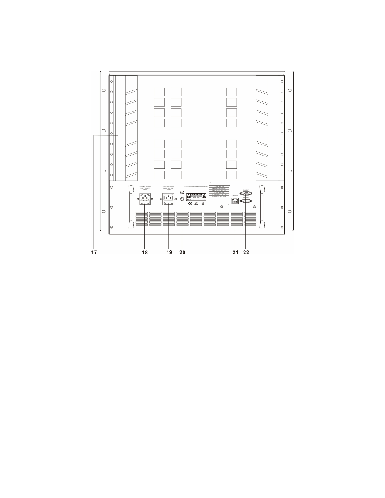
6.6 Real Panel
◆ TS-9232H (32 channels)
17) Slot for output panel and input panel.
18) AC ~110-220V 50-60Hz power input.
19) ~110-220V 50-60Hz main power input.
20) Ground point.
21) Ethernet Interface (RJ-45main interface).
22) Serial Control Interface.
Page 14

13
7. serial port instruction control
It tests machine by PC series port, connect the test sample by the serial port cable,set PC
series port test machine's Baud rate to be 9600bps, data:8bits, stop:1bit, correction digit:
w/o, flow control: w/o. serial port instructions are design to offer the control for center control
system. It can be connected PC to internet access for internet testing , set same serial port
instruction, network parameter could be defined by the serial port instruction.
8. Instruction operation
Instruction character description:
[X1],[X2], … ,[Xn] means the corresponding input port
[Y1],[Y2], … ,[Yn] means the corresponding output port
[TX1],[TX2], … ,[TXn] means the corresponding input series port/IR transmition channel
[RX1], [RX2], … , [RXn] means the corresponding input series port/IR reception channel
[TY1] ,[TY2], … , [TYn] means the corresponding output series port/IR transmition channel
[RY1] , [RY2], … ,[RYn] means the corresponding output series port/IR reception channel
n is the device's input/output ports quantity, eg: TS-9232H,n max 32.
Page 15
14
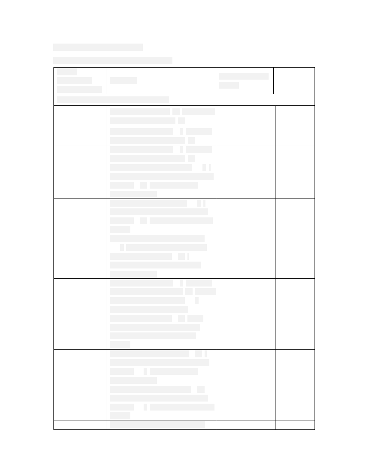
9. Instructions Description
9.1 Build the instruction connection
ASCII
Instruction
(PC to matrix)
Function
Return (matrix
to PC)
Example
build the single channel connection
[X1]V[Y1].
audio and video input[X1] connect to
audio and video output[Y1]
AV:[X1]->[ Y1] 1V1.
[X1]A[Y1].
audio and video input [X1] connect
to audio and video output [Y1]
AV:[X1]->[ Y1] 1A1.
[X1]B[Y1].
audio and video input [X1] connect
to audio and video output [Y1]
AV:[X1]->[ Y1] 1B1.
[RX1]R[TY1].
input port reception channel [RX1]
connect to output port transmition
channel [TY1] (RS232 forward
direction switch)
RS:[RX1]->[TY1] 1R1.
[RX1]Q[TY1].
input IR reception channel [RX1]
connect to output IR transmition
channel [TY1] (IR forward direction
switch)
IR:[RX1]->[TY1] 1Q1.
[RX1]T[TY1].
input port/IR reception channel
[RX1] connect to output port/IR
transmition channel [TY1]
(RS232/IR forward and reverse
direction switch)
RS:[RX1]->[TY1]
IR:[RX1]->[TY1]
1T1.
[X1]W[Y1].
audio and video input [X1] connect
to audio and video output [Y1], input
port/IR reception channel [RX1]
connect to output port/IR
transmition channel [TY1] ( AV
forward direction , RS232/IR
forward and reverse direction
switch)
AV:[X1]->[ Y1]
RS:[RX1]->[TY1]
IR:[RX1]->[TY1]
1W1.
[RY1]~R[TX1].
output C reception channel [RY1]
connect to input port transmition
channel [TX1] (RS232 reverse
direction switch)
~RS:
[RY1]->[TX1]
1~R2.
[RY1]~Q[TX1].
output IR reception channel [RY1]
connect to input IR transmition
channel [TX1] ( IR reverse direction
switch)
~IR:
[RY1]->[TX1]
1~Q2.
[RY1]~T[TX1].
output port/IR reception channel
~RS: 1~T2.
Page 16
15
[RY1] connect to input port/IR
transmition channel [TX1]
( RS232/IR reverse direction switch)
[RY1]->[TX1]
~IR:
[RY1]->[TX1]
[X1]*[ Y1]&
audio and video input [X1] connect
to audio and video output [Y1]
AV:[X1]->[ Y1] 1*1&
[X1]*[ Y1]%
audio and video input [X1] connect
to audio and video output [Y1]
AV:[X1]->[ Y1] 1*1%
[X1]*[ Y1]$
audio and video input [X1] connect
to audio and video output [Y1]
AV:[X1]->[ Y1] 1*1$
[X1]*[ Y1]!
audio and video input [X1] connect
to audio and video output [Y1]
AV:[X1]->[ Y1] 1*1!
[X1]#.
audio and video input [X1] connect
to audio and video output [Y1];
input port/IR reception channel
[RX1] connect to output port/IR
transmition channel [TY1];
output port/IR reception channel
[RY1] connect to input port/IR
transmition channel [TY1]
[X1]
A/V/R/I Through.
1#.
Quickly to build multi channels connection
[X1]V[Y1],[Y2]·
··,[Yn]
Single AV input [X1] connect to
multi AV output [[Y1],[Y2],···,[ [Yn]
AV:[X1]->[Y1]
AV:[X1]->[Y2]
···
AV:[X1]->[Yn]
1V1,2,3.
[X1]A[Y1],[Y2]·
··,[Yn]
Single AV input [X1] connect to
multi AV output [[Y1],[Y2],···,[ [Yn]
AV:[X1]->[Y1]
AV:[X1]->[Y2]
···
AV:[X1]->[Yn]
1A1,2,3.
[X1]B[Y1],[Y2]·
··,[Yn]
Single AV input [X1] connect to
multi AV output [[Y1],[Y2],···,[ [Yn]
AV:[X1]->[Y1]
AV:[X1]->[Y2]
···
AV:[X1]->[Yn]
1B1,2,3.
[RX1]R[Y1],[Y2
]···,[Yn]
Single input serial port receive
channel [RX1] connect to multi
output of serial port transmit
channels [[TY1],[TY2],···,[ [TYn]
(RS232 switch to multi channels at
forward direction)
RS:[RX1]->[TY1]
RS:[RX1]->[TY2]
···
RS:[RX1]->[RYn]
1R1,2,3.
[RX1]Q[Y1],[Y2
]···,[Yn]
Single input infrared receive
channel [RX1] connect to multi
IR:[RX1]->[TY1]
IR:[RX1]->[TY2]
1Q1,2,3.
Page 17

16
output of infrared transmit
channels [[TY1],[TY2],···,[ [TYn]
(IR switch to multi channels at
forward direction)
···
IR:[RX1]->[RYn]
[RX1]Q[Y1],[Y2
]···,[Yn]
Single input serial port/infrared
receive channel [RX1] connect to
multi output of serial port/infrared
transmit channels
([TY1],[TY2],···,[ [TYn] (RS232/IR
switch to multi channels at forward
direction)
RS:[RX1]->[TY1]
IR:[RX1]->[TY1]
RS:[RX1]->[TY2]
IR:[RX1]->[TY2]
···
RS:[RX1]->[RYn]
IR:[RX1]->[RYn]
1T1,2,3.
[X1]W[Y1],[Y2]·
··,[Yn]
Single AV input [X1] connect to
multi channels AV output
[[Y1],[Y2],···,[ [Yn]
Single input serial port/infrared
receive channel [RX1] connect to
multi output of serial port/infrared
transmit channels
[[TY1],[TY2],···,[ [TYn]
(AV/RS232/IR switch to multi
channels)
AV:[X1]->[Y1]
RS:[RX1]->[TY1]
IR:[RX1]->[TY1]
AV:[X1]->[Y2]
RS:[RX1]->[TY2]
IR:[RX1]->[TY2]
···
AV:[X1]->[Yn]
RS:[RX1]->[RYn]
IR:[RX1]->[RYn]
1W1,2,3
[RY1]~R[TX1],[
TX2]···,[TYn]
Single output serial port receive
channel [RY1] connect to multi
input of serial port transmit
channels [[TX1],[TX2],···,[ [TXn]
(RS232 switch to multi channels at
reverse direction)
~RS:[RY1]->[TX1]
~RS:[RY1]->[TX2]
···
~RS:[RY1]->[RXn]
1~R1.,2,3
[RX1]Q[Y1],[Y2]
···,[Yn]
Single output infrared receive
channel [RY1] connect to multi
input of infrared transmit
channels [[TX1],[TX2],···,[ [TXn]
(IR switch to multi channels at
reserve direction)
~IR:[RY1]->[TX1]
~IR:[RY1]->[TX2]
···
~IR:[RY1]->[RXn]
1~Q1,2,3.
[RX1]Q[Y1],[Y2]
···,[Yn]
Single output serial port/infrared
receive channel [RY1] connect to
multi input of serial port/infrared
transmit channels
[[TX1],[TX2],···,[ [TXn] (RS232/IR
switch to multi channels at reserve
direction)
~RS:[RY1]->[TYX]
~IR:[RY1]->[TX1]
~RS:[RY1]->[TX2]
~IR:[RY1]->[TX2]
···
~RS:[RY1]->[RXn]
~IR:[RY1]->[RXn]
1~T,1,2,3.
[X1] All
Single AV input [X1] connect to all
the AV output,
Single input serial port/infrared
receive channel [RX1] connect to
[X1]
A/V/R/1 To All
1 All
Page 18
17
all the output of serial port/infrared
transmit channels [Yn]
[X1],[X2]···
,
[Xn] #.
Multi AV input [X1] [X2],···,[ [Xn]
one-to-one connect to multi AV
output [[Y1],[Y2],···,[ [Yn],
Multi input serial port/infrared
receive channel
[RX1],[RX2],···,[ [RXn]
one-to-one connect to multi output
of serial port/infrared transmit
channels ([TY1],[TY2],···,[ [TYn],
Multi output serial port/infrared
receive channel
[RY1],,[RY2],···,[ [RYn] one-to-one
connect to multi input channels of
serial port/infrared transmit
channels [[TX1],[TX2],···,[ [TXn]
[X1]
A/V/R/1 Through,
[X2]
A/V/R/1 Through,
···
[Xn]
A/V/R/1 Through
1,2,3#
All#
All the AV input [Xn] one-to-one
connect to all the AV output,
All the input of serial port/infrared
receive channels [RXn] one-to-one
connect to all the output of serial
port/infrared transmit channels
[ [TYn],
All the output of serial port/infrared
receive channels [RYn] one-to-one
connect to all the input of serial
port/infrared transmit channels
[[TX1],[TX2],···,[ [TXn]
All
A/V/R/1 Through
All#
Noted: All the switch instructions could be transmitted at the same time by multiple of all
kinds, for example (1V1,1R1,1Q2.2~R1), they would be executed one by one from the matrix
cache.
Page 19
18
9.2 Close the instruction connection
ASCII
command(fro
m PC to
matrix)
Command function
Return(from
matrix to PC)
Example
Close single way connection
0V[Y1]. Close one way AV output [Y1] B:OFF->[Y1]! 0V1.
0A[Y1]. Close one way AV output [Y1] B:OFF->[Y1]! 0A1.
0B[Y1]. Close one way AV output [Y1] B:OFF->[Y1]! 0B1.
0R[TY1].
Close one way output serial port
dispatching channel [TY1]
RS:OFF->[TY1]! 0R1.
0Q[TY1].
Close one way output infrared
dispatching channel [TY1]
IR:OFF->[TY1]! 0Q1.
0T[TY1].
Close one way output serial port/
infrared dispatching channel [TY1]
RS:OFF->[TY1]!
IR:OFF->[TY1]!
0T1.
0W[Y1].
Close one way AV output [Y1] and
output serial port infrared
dispatching channel [TY1]
B:OFF->[ Y1]!
RS:OFF->[TY1]!
IR:OFF->[TY1]!
0W1.
0~R[TX1].
Close one way input serial port
dispatching channel [TX1]
~RS:OFF->[TX1]! 0~R1.
0~Q[TX1].
Close one way input infrared
dispatching channel [TX1]
~IR:OFF->[TX1]! 0~Q1.
0~T[TX1].
Close one way input serial port /
infrared dispatching channel [TX1]
~RS:OFF->[TX1]!
~IR:OFF->[TX1]!
0~T1.
0*[Y1]& Close one way AV output [Y1] B:OFF->[Y1]! 0*1&
0*[Y1]% Close one way AV output [Y1] B:OFF->[Y1]! 0*1%
0*[Y1]$ Close one way AV output [Y1] B:OFF->[Y1]! 0*1$
0*[Y1]! Close one way AV output [Y1] B:OFF->[Y1]! 0*1!
[Y1]$. Close one way AV output [Y1] B:OFF->[Y1]! 1$.
Quickly to Close single way connection
[Y1],[Y2],…,
[Yn]$.
Close multi channel AV output
[Y1],[Y2],…,[Yn]
B:OFF->[Y1]!
B:OFF->[Y2]!
…
B:OFF->[Yn]!
1,2,3$.
[TY1],[TY2],…,
[TYn]R$.
Close multi channel output serial
port dispatching channel
[TY1],[TY2],…,
[TYn]
RS:OFF->[TY1]!
RS:OFF->[TY2]!
…
RS:OFF->[TYn]!
1,2,3R$.
[TY1],[TY2],…,
[TYn]Q$.
Close multi channel output port
infrared dispatching channel
[TY1],[TY2],…,
[TYn]
IR:OFF->[TY1]!
IR:OFF->[TY2]!
…
IR:OFF->[TYn]!
1,2,3Q$.
Page 20

19
[TY1],[TY2],…,
[TYn]T$.
Close multi channel output serial
port / infrared dispatching channel
[TY1],[TY2], …,[TYn]
RS:OFF->[TY1]!
IR:OFF->[TY1]!
RS:OFF->[TY2]!
IR:OFF->[TY2]!
…
RS:OFF->[TYn]!
IR:OFF->[TYn]!
1,2,3T$.
[Y1],[Y2],…,
[Yn]W$.
Close multi channel AV output
[Y1],[Y2],…,[Yn]
Close multi channel output serial
port / infrared dispatching channel
[TY1],[TY2],…,[TYn]
B:OFF->[Y1]!
RS:OFF->[TY1]!
IR:OFF->[TY1]!
B:OFF->[Y2]!
RS:OFF->[TY2]!
IR:OFF->[TY2]!
…
B:OFF->[Yn]!
RS:OFF->[TYn]!
IR:OFF->[TYn]!
1,2,3W$.
[TX1],[TX2],…,
[TXn]~R$.
Close multi channel input serial
port dispatching channel
[TX1],[TX2],…, [TXn]
RS:OFF->[TX1]!
RS:OFF->[TX2]!
…
RS:OFF->[TXn]!
1,2,3~R$.
[TX1],[TX2],…,
[TXn]~Q$.
Close multi channel input infrared
dispatching channel
[TX1],[TX2],…,[TXn]
IR:OFF->[TX1]!
IR:OFF->[TX2]!
…
IR:OFF->[TXn]!
1,2,3~Q$.
[TX1],[TX2],…,
[TXn]~T$.
Close multi channel input serial
port / infrared dispatching channel
[TX1],[TX2],…,[TXn]
RS:OFF->[TX1]!
IR:OFF->[TX1]!
RS:OFF->[TX2]!
IR:OFF->[TX2]!
…
RS:OFF->[TXn]!
IR:OFF->[TXn]!
1,2,3~T$.
Page 21
20
9.3 Channel Connection Instructions
Status.
Check all the connection situation
of all audio & video frequency
output
A:[X1]->[Yn]
V:[X1]->[Yn]
…
A:[X2]->[Yn]
V:[X2]->[Yn]
…
A:[Xn]->[Yn]
V:[Xn]->[Yn]
…
Status1,2,
3
Inquire.
Check all serial ports / infrared
channel connection situation
RS:[RX1]->[TYn]
IR:[RX1]->[TYn]
Inquire.
ASCII
command(from
PC to matrix)
Command function
Return(from
matrix to PC)
Example
Status[X1][X2],
…[Xn].
Inquire connection status of single
channel or multi-channel
video input [X1] [X2] …[Xn]
A:[X1]->[Yn]
V:[X1]->[Yn]
…
A:[X2]->[Yn]
V:[X2]->[Yn]
…
A:[Xn]->[Yn]
V:[Xn]->[Yn]
…
Status
1,2,3
Inquire[X1],[X2],
…[Xn]
Inquire serial input port /Infrared
data [RX1] , [RX2],…,
The connection status of [RXn]
and output Transmit channel
[TY1],[TY2],…[TXn] and
connection status of serial output
port/Infrared data receiver
channel [RY1] [RY2]…,
[RYn] and input port transmit
channel [TX1] [TX2],…[TXn]
(Inquire of connection Forward
and reverse channel RS232/IR)
RS:[RX1]- >[TYn]
IR:[RX1]->[TYn]
…
RS:[RX2]- >[TYn]
IR:[RX2]->[TYn]
…
RS:[RXn]- >[TYn]
IR:[RXn]->[TYn]
…
~RS:[RY1]- >[TXn]
~IR:[RY1]->[TXn]
…
~RS:[RY2]- >[TXn]
~IR:[RY2]->[TXn]
…
~RS:[RYn]- >[TXn]
~IR:[RYn]->[TXn]
…
Inquire
1,2,3
Page 22
21
(forward & reverse) …
RS:[RX2]->[TYn]
IR:[RX2]->[TYn]
…
RS:[RXn]->[TYn]
IR:[RXn]->[TYn]
…
~RS:[RY1]->[TXn]
~IR:[RY1]->[TXn]
…
~RS:[RY2]->[TXn]
~IR:[RY2]->[TXn]
…
~RS:[RYn]->[TXn]
~IR:[RYn]->[TXn]
…
9.4 Overall Presetting Order
ASCII
command(from
PC to matrix)
Command function
Return(from
matrix to PC)
Example
Save[N].
N=1,2,3,…,8.
Restore all audio & video
frequency/serial ports /
infrared gateway connection
situation to the N overall
presetting
Save To F[N] Save2.
Recall[N].
Take out the N overall presetting
as the current gateway connection
Recall From F[N] Recall2.
Clear[N]. Delete the N overall presetting Clear F[N] Clear2.
9.5 Safety Allocation Order
ASCII
command(from
PC to matrix)
Command function
Return(from
matrix to PC)
Example
/%Lock; Lockup control panel keyboard System Locked! /%Lock;
/%Unlock; Relieve control panel System Unlocked! /%Unlock;
PS: panel just can be locked up or relieved by gateway order.
Page 23
22
9.6 System Allocation Order
ASCII
command(from
PC to matrix)
Command function
Return(from
matrix to PC)
Example
/:Bell Off; Close buzzer warning tone Closed The Bell. /:Bell Off;
/:Bell On; Open buzzer warning tone Opened The Bell. /:Bell On;
/:Message Off;
Close the returned information
sent to computer gateway
Closed The Message
Return.
/:Message
Off;
/:Message On;
Open the returned information
sent to computer port
Enabled The
Message Return.
/:Message
On;
9.7 Network Allocation Order
ASCII
command(from
PC to matrix)
Command function
Return(from
matrix to PC)
Example
<#SPORT[5000]> Allocate matrix network gateway
number
SPORT\: [5000] <#SPORT5
000>
<#SIPR[192].
[168]. [0]. [2]>
Allocate matrix network IP SIPR:[192].[168].
[0].[2]
<#SIPR19
2.168.0.2>
<#GAR [192].
[168]. [0]. [1]>
Allocate network gateway
number
GAR:[192].[168].
[0].[1]
<#GAR192
.168.0.1>
<#SUBR [255].
[255]. [255].
[0]>
Allocate network sub net mask SUBR:[255].[255].
[255].[0]
<#SUBR25
5.255.
255.0>
<# SHAR 0x[00].
0x[11].
0x[22]. [0x33].
[0x44]. [0x55]>
Allocate network hardware
address (16B)
0x[00]. 0x[11].
0x[22].
[0x33]. [0x44].
[0x55]>
<#SHAR0x
00.0x11.
0x22.0x33.
0x44.0x55
>
<#NETDEFAULT> Network allocation recover
factory value
NETDEFAULT:[OK]
<#NETDEF
AULT>
Allocate network data error Out of range!
Allocate network successfully NETSET:OK
PS: allocate the wrong network data, will return to “Out of range!”, allocate network
successfully, will return to “NETSET:OK”.
9.8 System Checking Order
ASCII
command(from
PC to matrix)
Command function
Return(from
matrix to PC)
Example
/^Version;
Check matrix system version
number
[X4] /^Version;
Page 24
23
/*Type; Check matrix model [X5] /*Type;
<^SPORT>
Check current matrix network
port number
SPORT:[X12] <^SPORT>
<^SIPR>
Check current matrix IP network
number
SIPR:[X12].[X13].
[X14].[X15]
<^SIPR>
<^SUBR>
Check current network sub net
mask number
SUBR:[X12].[X13].
[X14].[X15]
<^SUBR>
<^GAR> Check current network gateway
number
GAR:[X12].[X13].
[X14].[X15]
<^GAR>
<^SHAR> Check current network hardware
address number
SHAR:[X12].[X13].
[X14].[X15].[X16].
[X17]
<^SHAR>
9.9 Common Usage Allocation Order
ASCII
command(from
PC to matrix)
Command function
Return(from
matrix to PC)
Example
Standard switch
[xxx].
Switch standard work mode
(xxx=255,operate all output)
STANDARDSWIT
CH002!
Standard
switch.2
Fast switch[xxx].
Switch quick work mode
(acquiescence) (xxx=255,
operate all output)
FASTSWITCH002! Fastswitch2.
[Y1]D[X1],
[X2],…,[Xn].
Read monitor EDID to input port
connecting output port[Y1]
[X1],[X2],…,[Xn].
When output port [Y1]: 0, means
recover the acquiescent EDID to
the related output port
input port [Xn] require the same
input board, one time only can be
written 8-channel (for example)
(1D1,2,3,4,5,6,7,8.)
EDID-OK! (success)
EDID-FAIL! (fail)
1D1,2,3,8.
WEDIDx.
Send EDID to output board,
restore in EEPROM
send”CONFIGEDIDCODE.” Then
send EDID data.
Send WEDIDx. (x=1 to 8
)
WEDIDx. WEDID1.
ROUTPUTDID
[Y1].
Read output port EDID to
terminal
256 byte EDID,if no
connection monitor,
return 0
ROUTPU
TDID1.
R BLOCK E DID x.
Read output board EPROM x
situation EDID to terminal
256 byte EDID data RBLOCKE
DID1.
[X]WBEDID[Y] Read output board EDID[X] to CALLEDID[X],[Y]. 2WBEDI
Page 25
24
input board channel [Y] D6.
DOG: Out Mode
AUTO[XXX].
Allocate output board channel to
AUTO mode (xxx=255,operate
all output)
DOG:Out Mode AUTO
[XXX].
DOG:Out
ModeAUTO7
DOG:Out Mode
DVI[XXX].
Allocate output board channel to
DVI mode (xxx=255, operate all
output)
DOG:Out Mode DVI
[XXX].
DOG:Out
ModeDVI7.
DOG:Out Mode
HDMI[xxx].
Allocate output board channel to
HDMI mode(xxx=255, operate
all output)
DOG:Out Mode HDMI
[xxx].
DOG:Out
ModeHDMI7
.
DOG:Deep On
[xxx].
Allocate output board channel to
open high color depth function
(xxx=255, operate all output)
DOG:Deep On[xxx]. DOG:
DeepOn7.
DOG:Deep Off
[xxx].
Allocate output board channel to
close high color depth function
(xxx=255, operate all output)
DOG:Deep Off[xxx]. DOG:
DeepOff7.
10. Network Interface Acquiescent Data
Matrix Network Port No: 5000
Matrix Network IP: 192.168.0.2
Matrix Network Gateway No: 192.168.0.1
Matrix Network Sub net Mask: 255.255.255.0
Matrix Network Hardware Add: 0x00.0x11.0x22.0x33.0x44.0x55;
PS: RST matrix system allocated network data just work.
11. Notice to switch serial ports, infrared data
◆ RS-232 & infrared operating are positive (positive: matrix input port connect RS-232
or infrared receiver side, output port connect RS-232 or infrared sending side).
◆ RS-232& infrared negative switch need the serial ports order (negative: matrix output
port connect RS-232 or infrared receiver side, output port connect RS-232 or infrared
sending side), the serial ports order please refer the serial ports specification.
◆ Infrared or serial ports switch (positive & negative) just can change from one channel
to another one or more, cannot all channels to one channel.
Page 26

25
12. Power supply scope test
◆ Test Requirements: input AC ~100-240V, measure DC voltage.
◆ Test Standard: debug sample machine to DC working voltage normal, function well.
13. High voltage debug
Power source L/N line add 1500V/5mA AC to floor, continue 60s, high voltage tester doesn’t
warn, the tested equipment no damage, no creepage.
14. Low impedance test
Use low impedance tester to test earthing resistance, the value should less than 0.1Ω.
Page 27
26
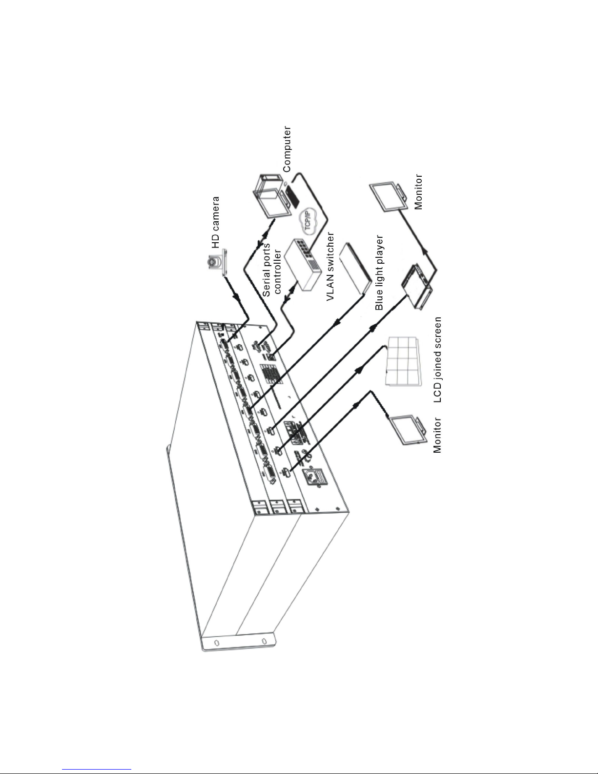
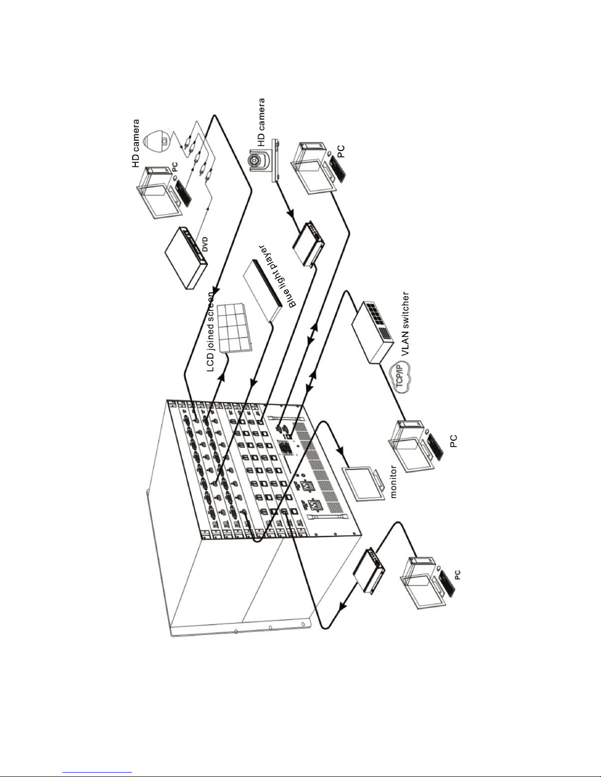
15. System connection drawing
◆ TS-9208H
Page 28
27
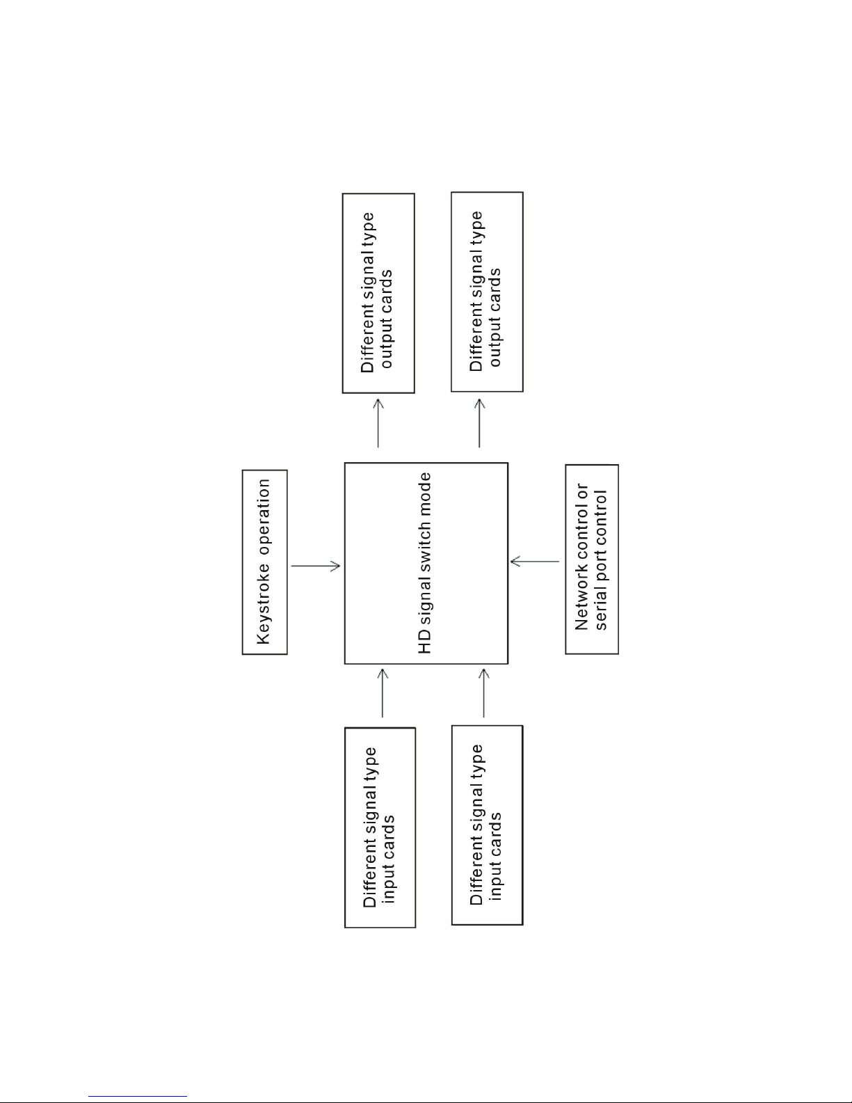
◆ TS-9216H/TS-9232H
Page 29
28
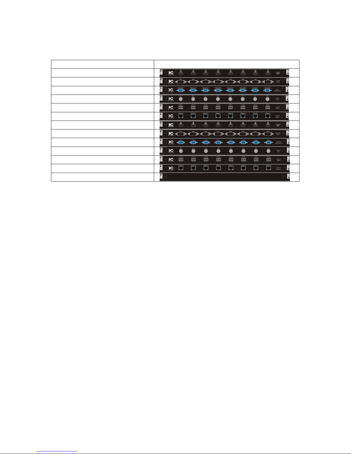
16. Theory block plan
Page 30
29
17. Input, output board card specification
Board cards type
Model/name outlook
TS-9208HR input board card
TS-9208DR input board card
TS-9208CR input board card
TS-9208SR input board card
TS-9208GR input board card
TS-9208TR input board card
TS-9208HC output board card
TS-9208DC output board card
TS-9208CC output board card
TS-9208SC output board card
TS-9208GC output board card
TS-9208TC output board card
Blank card
18. Input board card
◆
TS-9208HR input board card functions
● 8-channel HDMI-A parent interface input.
● The input longest substance: 20M.
● Support EDID edition function.
● Compatible with HDMI1.4 standard, HDCP1.3 agreement, DVI1.0 agreement.
● The largest supported resolving capability:HDPC: 1920x1200P@60_24bit.
HDTV: 1920x1080P@60_36bit.
● Plug and Play; easy to use.
◆
TS-9208DR input board card functions
● 8-channel HDMI-A parent interface input.
● The input longest substance: 20M.
● Support EDID edition function.
● Compatible with HDMI1.4 standard, HDCP1.3 agreement, DVI1.0 agreement.
● The largest supported resolving capability:HDPC: 1920x1200P@60_24bit.
HDTV: 1920x1080P@60_36bit.
● Plug and Play; easy to use.
Page 31

30
◆ TS-9208CR input board card functions
● 8-Channel DB15 interface input.
● Select any signal input of VGA,CVBS,YPbPr,S-Video.
● HDPC: 1920x1200P@60_24bit.
HDTV: 1920x1080P@60_36bit.
● Input the max supporting resolution ratio: HDPC: 1920x1200P@60_24bit.
HDTV: 1920x1080P@60_36bit.
● Times cable output resolution ratio max at 1920x1080P@60Hz.
● Plug and Play; easy to use.
◆ TS-9208SR input board card functions
● 8-Channel BNC female interface input.
● Supporting SD-SDI, HD-SDI and 3G-SDI AV mode.
● Supporting SMPTE 425M, SMPTE 424M, SMPTE 292M, SMPTE 259M-C, DVB-ASI protocols.
● Maximum solution up to 1080P; HDTV compatible.
● Plug and Play; easy to use.
◆ TS-9208GR input board card functions
● 8-Channel optical signal input.
● Maximum solution up to 1080P.
● LC single chip and single mode technology with a maximum transporting distance of 20km.
● Full digital zero compression technology; high-performance signal transportation.
● Maximum input solution: HDPC: 1920x1200P@60_24bit.
HDTV: 1920x1080P@60_36bit.
● Plug and Play; easy to use.
◆ TS-9208TR input board card functions
● 8-line high-speed RJ45 interface input.
● Adopting CAT5e/6 cable input with the max distance at 100M.
● Pixel bandwidth: 225MHZ, full digital.
● Interface bandwidth: 3.25Gbps, full digital (Each color is 3.25Gbps).
Page 32

31
● Supporting EDID function.
● Compatible HDBaseT protocol.
● Max supporting resolution ratio: HDPC:1920X1200P@60_24bit,
HDTV:1920x1080p@60_36bit.
● Plug and Play; easy to use.
18.2 Output board card
◆ TS-9208HC output board card functions
● 8-Channel HDMI-A interface output.
● The input longest substance: 20M.
● Pixel bandwidth: 225MHz, full digital.
● Interface bandwidth: 3.25Gbps, full digital(Each color is 3.25Gbps).
● Supporting EDID function.
● Max supporting resolution ratio: HDPC:1920x1200P@60_24bit.
HDTV:1920x1080p@60_36bit.
● Plug and Play; easy to use.
◆ TS-9208DC output board card functions
● 8-Channel DVI-D interface output.
● The input longest substance: 20M.
● Pixel bandwidth: 225MHz, full digital.
● Interface bandwidth: 3.25Gbps, full digital(Each color is 3.25Gbps).
● Supporting EDID function.
● Max supporting resolution ratio: HDPC:1920x1200P@60_24bit.
HDTV:1920x1080p@60_36bit.
● Plug and Play; easy to use.
◆ TS-9208CC output board card functions
● 8-line DB15 interface output.
● Any signal of VGA, CVBS and YPbPr can be selected.
Page 33

32
● Maximum input solution: HDPC: 1920x1200P@60_24bit.
HDTV: 1920x1080P@60_36bit.
● Maximum solution of fold line output (can be set) up to 1920x1080P@60Hz.
● Plug and Play; easy to use.
◆ TS-9208SC output board card functions
● 8-way BNC female interface input.
● Supporting SD-SDI, HD-SDI and 3G-SDI AV mode.
● Supporting SMPTE 425M, SMPTE 424M, SMPTE 292M, SMPTE 259M-C, DVB-ASI protocols.
● Maximum solution up to 1080P; HDTV compatible.
● Plug and Play; easy to use.
◆ TS-9208GC output board card functions
● 8-Channel optical signal input.
● Maximum solution up to 1080P.
● LC single chip and single mode technology with a maximum transporting distance of 20km.
● Full digital zero compression technology; high-performance signal transportation.
● Maximum input solution: HDPC: 1920x1200P@60_24bit.
HDTV: 1920x1080P@60_36bit.
● Plug and Play; easy to use.
◆ TS-9208TC output board card functions
● 8-Channel high speed RJ45 interface output.
● Adopting CAT5e/6 cable input max distance at 100M.
● Pixel bandwidth: 225MHZ, full digital.
● Interface bandwidth: 3.25Gbps, full digital(Each color is 3.25Gbps).
● Compatible HDBaseT protocol.
● Max supporting resolution ratio: HDPC:1920X1200P@60_24bit,
HDTV:1920x1080p@60_36bit.
● Plug and Play; easy to use.
Page 34

33
18.3 Accessories for choice
◆ Blank card functions
● Blank, fill in the blank short section without the available audio & video frequency
input/output.
◆ Power supply box functions
● International universal all scopes AC input (AC ~100V-240V 50-60Hz);
● AC in burst current suppression circuit;
● With short circuit/overload/over voltage/over temperature protection functions;
● Offer system internal+5V (425W), +12V (480W) power;
● Support power source redundant cold backup, switch fast on spot.
Page 35

34
19. Specifications
TS-9208HR
Model TS-9208HR
Interface 8-channel HDMI-A parent interface input
Agreement
Support HDMI1.4 agreement, HDCP1.3 agreement,
DVI1.0 agreement.
Pixel bandwidth 225MHz,full digital
Connector bandwidth 3.25Gbps, full digital
The largest supported resolving
capability
HDPC:1920x1200p@60_24bit;
HDTV:1920x1080P@60_36bit;
Normal-PC:1600x1200p@60_24bit
Clock Jitter <0.15T bit
Rise time <0.3Tbit (20%-80%)
Fall time <0.3Tbit (20%-80%)
Interface 8-channel HDMI-A parent interface
Signal strength T.M.D.S.+/-0.4vpp
The minimum/maximum level T.M.D.S.2.9V/3.3V
EDID An optional default read EDID and function
The maximum error of the dc
bias
15mV
Recommended maximum
input/output range
Input is less than 20M, in 1920x1200@60 (it is
recommended to use certified HDMI special wire,
such as Model TM x wire
product weight About 0.5Kg
Power consumption 12W
Page 36

35
TS-9208HC
Model TS-9208HC
Interface 8-channel HDMI-A parent interface input
Agreement
Support HDMI1.4 agreement, HDCP1.3 agreement,
DVI1.0 agreement.
Pixel bandwidth 225MHz,full digital
Connector bandwidth 3.25Gbps, full digital
The largest supported resolving
capability
HDPC:1920x1200p@60_24bit;
HDTV:1920x1080P@60_36bit;
Normal-PC:1600x1200p@60_24bit
Clock Jitter <0.15T bit
Rise time <0.3Tbit (20%-80%)
Fall time <0.3Tbit (20%-80%)
Interface 8-channel HDMI-A parent interface
Signal strength T.M.D.S.+/-0.4vpp
The minimum/maximum level T.M.D.S.2.9V/3.3V
EDID An optional default read EDID and function
The maximum error of the dc
bias
15mV
Recommended maximum
input/output range
output is less than 20M, in 1920x1200@60 (it is
recommended to use certified HDMI special wire,
such as Model TM x wire
product weight About 0.5Kg
Power consumption 10W
Page 37

36
TS-9208DR
Model TS-9208DR
Interface 8-channel DVI-D Input board card
Agreement
Support HDMI1.4 agreement, HDCP1.3 agreement,
DVI1.0 agreement
Pixel bandwidth 225MHz,full digital
Connector bandwidth 3.25Gbps, full digital
The largest supported resolving
capability
Normal-PC:1600x1200P@60_24bit,
HDPC:1920x1200P@60_24bit,
HDTV:1920x1080P@60_36bit,
Clock Jitter <0.15T bit
Rise time <0.3Tbit (20%-80%)
Decline in time <0.3Tbit (20%-80%)
Signal strength T.M.D.S.+/-0.4pp
The minimum/maximum level T.M.D.S.2.9V/3.3V
EDID An optional default read EDID and function
The maximum error of the dc
bias
15mV
Recommended maximum
input/output range
Input is less than 20M, in 1920x1200@60 (it is
recommended to use certified DVI special wire, such
as Model TM x wire
Product weight About 0.5Kg
Power consumption 12W
Page 38

37
TS-9208DC
Model TS-9208DC
Interface 8-channel DVI-D Input board card
Agreement
Support HDMI1.4 agreement, HDCP1.3 agreement,
DVI1.0 agreement
Pixel bandwidth 225MHz,full digital
Connector bandwidth 3.25Gbps, full digital
The largest supported resolving
capability
Normal-PC:1600x1200P@60_24bit,
HDPC:1920x1200P@60_24bit,
HDTV:1920x1080P@60_36bit,
Clock Jitter <0.15T bit
Rise time <0.3Tbit (20%-80%)
Decline in time <0.3Tbit (20%-80%)
Signal strength T.M.D.S.+/-0.4pp
The minimum/maximum level T.M.D.S.2.9V/3.3V
EDID An optional default read EDID and function
The maximum error of the dc
bias
15mV
Recommended maximum
input/output range
Input is less than 20M, in 1920x1200@60 (it is
recommended to use certified DVI special wire, such
as Model TM x wire
Product weight About 0.5Kg
Power consumption 10W
Page 39
38
TS-9208CR
Model TS-9208CR
Interface 8-Channel DB15 interface input
Selective output resolution ratio 800 x 600@60Hz; 1024 x 768@60Hz;
1280 x 720P@60Hz; 1280 x 800@60Hz;
1280 x 1024@60Hz; 1366 x 768@60Hz;
1440 x 900@60Hz; 1400 x 1050@60Hz;
1600 x 900@60Hz; 1600 x 1200@60Hz;
1680 x 1050@60Hz; 1920 x 1080P@60Hz ;
Max consumption 50W
Product weight 1.2kg
CV Composite video CV
Gain 0dB
Bandwidth 150MHz @ -3dB
Differential phase error 0.1°, 3.58-4.43 MHz
Differential gain error 0.1% , 3.58-4.43 MHz
Signal strength 1Vpp: Composive vedio (CVBS)
Mini/max electrical level Analog signal: -2V/+2V
Input impedance 75Ω
Return Loss <-30dB@5MHz
Y/C Video frequency
Gain 0dB
Bandwidth 150MHz @ -3dB
Differential phase error 0.1°, 3.58-4.43 MHz
Differential gain error 0.1% , 3.58-4.43 Mhz
Signal strength 1Vpp: S Terminal video(Y/C)
Mini/max electrical level Analog signal: -2V/+2V
Input impedance 75Ω
Return Loss <-30dB@5MHz
Component video YPbPr
Gain 0dB
Bandwidth 350MHz @ -3dB
Differential phase error 0.1°, 3.58-4.43 MHz
Differential gain error 0.1%, 3.58-4.43 MHz
Signal strength 1Vpp: (Component video Y)
0.3Vpp: (Component video Pb Pr/CbCr )
Page 40
39
Mini/max electrical level Analog signal: -2V/+2V
Input impedance 75Ω
Return Loss <-30dB@5MHz
VGA video
Gain 0dB
Bandwidth 380 MHZ
Signal strength 0.63Vpp to 0.9 Vpp
Mini/max electrical level RGB signal: 0V/1.0V
HV signal: 0V/5.0V
input impedance 75Ω
Return Loss <-30dB@5MHz
Page 41
40
TS-9208CC
Model TS-9208CC
Interface 8-line DB15 output interface
CV
Gain 0dB
Bandwidth 150MHz @ -3dB
Differential Phase Error 0.1°, 3.58-4.43 MHz
Differential Gain Phase Errors 0.1% , 3.58-4.43 MHz
Signal Strength 1Vpp: Composite Video (CVBS)
MIN/MAX Level Analogue signal: -2V/+2V
Input Impedance 75Ω
RL (Return Loss) <-30dB@5MHz
YPbPr
Gain 0dB
Bandwidth 350MHz@-3dB
Differential Phase Error 0.1%, 3.58-4.43 MHz
Differential Gain Phase Errors 0.1%, 3.58-4.43 MHz
Signal Strength 1Vpp: (Component Video: Y)
0.3Vpp: (Component Video: Pb Pr/CbCr )
MIN/MAX Level Analogue signal: -2V/+2V
Input Impedance 75Ω
RL (Return Loss) <-30dB@5MHz
VGA
gain 0dB
Bandwidth 380 MHZ
Signal Strength 0.63Vpp to 0.9 Vpp
MIN/MAX Level RGB signal: 0V/1.0V
HV signal: 0V/5.0V
Input Impedance 75Ω
RL (Return Loss) <-30dB@5MHz
Page 42
41
TS-9208SR
Model TS-9208SR
Interface Support 8-Channel BNC female interface input
Audio &video input
Supported Protocols SMPTE 425M, SMPTE 424M, SMPTE 292M,
SMPTE 259M-C, DVB-ASI
Pixel bandwidth 2.970Gb/s, 2.970/1.001Gb/s, 1.485Gb/s,
1.485/1.001G/bs, 270Mb/s
Maximum resolution 1920x1080P@60
Input return loss <-14dB @1MHz~1.5GHz
Output return loss <-12dB @1MHz~1.5GHz
Internal HDMI audio &video input
Supported Protocols Support HDMI1.3 standard, HDCP1.3 protocol,
DVI1.0 agreement
Pixel bandwidth 165MHz, full-digital
Interface bandwidth 3.25Gpbs
Maximum input resolution HDPC: 1920x1200P@60_24bit;
HDTV: 1920x1080P@60_36bit
Supported internal output
resolution
800X600@60Hz; 1024X768@60Hz;
1280X720@60Hz; 1280X1024@60Hz;
1280x768@60Hz; 1600x1200@60Hz;
1600X1200@60Hz; 1920X1080P@60Hz;
1920X1200P@60Hz; 1920x1200@60Hz;
Maximum Power Consumption 13W
Weight 1.4Kg
Page 43
42
TS-9208SC
Model TS-9208SC
Interface Support 8 channel BNC female interface output
Internal HDMI audio &video input
Supported Protocols Support HDMI1.3 standard, HDCP1.3 protocol,
DVI1.0 agreement; HDBaseT protocol
Pixel bandwidth 165MHz, full-digital
Interface bandwidth 3.25Gpbs
Internal maximum resolution 1920x1080P@60
SDI audio &video output
Supported Protocols SMPTE 425M, SMPTE 424M, SMPTE 292M,
SMPTE 259M-C, DVB-ASI
Pixel bandwidth 2.970Gb/s, 2.970/1.001Gb/s, 1.485Gb/s,
1.485/1.001G/bs, 270Mb/s
Supported resolution 1280X720@25HZ; 1280X720@30HZ;
1280X720@50HZ; 1280X720@60HZ;
1920X1080@24HZ; 1920X1080@25HZ;
1920X1080@30HZ; 1920X1080@50HZ;
1920X1080@60HZ;
Maximum output resolution 1920X1080@60
Maximum Power Consumption 13W
Weight 1.4Kg
Page 44

43
TS-9208GR
Model TS-9208GR
Input 8-Channel fiber signal (single code)
Input connector 8-Channel SPF fiber connector
Transmission power -5dB (standard)
Maximum Consumption 13dB
Wavelength
Multimode 850nm/Single Mode:
1310-1620nm(Alternative)
Multimode fiber spec. 50/125μm
Single-mode fiber spec. 9/125μm
Interface bandwidth 3.25Gbps, full-digital
Clock Jitter <0.15 Tbit
Rise time <0.3Tbit (20%--80%)
Fall time <0.3Tbit (20%--80%)
Maximum output distance OM3 Multimode fiber: Less than 300M Single-mode
fiber:2-20KM in 1920x1080p@60
Maximum Power Consumption 15W
Weight 1.5Kg
Page 45

44
TS-9208GC
Model TS-9208GC
Output 8-Channel fiber signal (single code)
Output connector 8-Channel SPF fiber connector
Transmission power -5dB(standard)
Maximum Consumption 13dB
Wavelength
Multimode 850nm/Single Mode:
1310-1620nm(Alternative)
Multimode fiber spec. 50/125μm
Single-mode fiber spec. 9/125μm
Interface bandwidth 3.25Gbps, full-digital
Clock Jitter <0.15 Tbit
Rise time <0.3Tbit (20%--80%)
Fall time <0.3Tbit (20%--80%)
Maximum output distance OM3 Multimode fiber :Less than 300M
Single-mode fiber:2-20KM in 1920x1080p@60
Maximum Power Consumption 15W
Weight 1.5Kg
Page 46
45
TS-9208TR
Model TS-9208TR
Interface 8-Channel high-speed RJ45 interface input
Protocol HDBaseT protocol
Pixel bandwidth 225MHz, full digital
Port bandwidth 3.25Gbps,full digital
Max supporting resolution ratio Normal-PC: 1600x1200@60_24bit
HDPC: 1920x1200P@ 60_24bit
HDTV: 1920x1080P@60_36bit
Signal type HDBaseT protocol high-speed differential signal
Max consumption 40W
Proposal max input distance The max 100 meters, at 1920x1080p@60Hz
(Recommend to use CAT5e/6/7 dedicated cables)
Product weight About 1KG
Page 47
46
TS-9208TC
Model TS-9208TC
Interface 8-Channel high speed RJ45 interface output
Pixel bandwidth 225MHz, full digital
Interface bandwidth 3.25Gbps,full digital
Max supporting resolution ratio Normal-PC: 1600x1200@60_24bit
HDPC: 1920x1200P@ 60_24bit
HDTV: 1920x1080P@60_36bit
Signal type HDBaseT protocol high speed differential signal
Max consumption 21W
Proposal max input distance
Max distance at 100 meters, at 1920x1S080p@60Hz
(recommend to use CAT5e/6/7 dedicated cables)
Product weight About 1Kg
Page 48
47
TS-9208H
Model TS-9208H
Connector
Input cards quantities 1
Output cards quantities 1
Input channel 8
Output cards quantities 8
Inserted input cards model
TS-9208HR/TS-9208DR/TS-9208CR/
TS-9208TR/TS-9208GR/TS-9208SR
Inserted output cards model
TS-9208HC/TS-9208DC/TS-9208CC/
TS-9208TC/TS-9208GC/TS-9208SC
Connector bandwidth 3.25Gbps, full Digital
Serial port control
Number 2
Serial port control connector RS-232
Baud rate and protocol
Baud rate:9600,data bits:8bits,
stop bit:1,without parity check bits
Serial port model 2=TX,3=RX,5=GND
Ethernet control
Ethernet control connector RJ-45
Ethernet control protocol TCP/IP
Ethernet control rate
Self-adaption 10M/100M, full duplex or
half-duplex
standard
power AC ~100V-240V, 50-60Hz
maximum power 107W
weight 6.3Kg
Temperature
-20℃~+70℃
humidity 10%-90%
Rack size 3U
Mean Time Between Failure
(MTBF)
30,000 hours
Size(mm) 484(L)*354(W)*132(H)
Page 49
48
TS-9216H
Model TS-9216H
Connector
Input cards quantities 2
Output cards quantities 2
Input channels 16
Output channels 16
Inserted input cards model
TS-9208HR/TS-9208DR/TS-9208CR/
TS-9208TR/TS-9208GR/TS-9208SR
Inserted output cards model
TS-9208HC/TS-9208DC/TS-9208CC/
TS-9208TC/TS-9208GC/TS-9208SC
Connector bandwidth 3.25Gbps, full digital
Serial port control
Number 2
Serial port control connector RS-232
Baud rate and protocol
Baud rate:9600,data bits:8,stop bit:1,without
parity check bits
Serial port model 2=TX,3=RX,5=GND
Ethernet control
Ethernet control connector RJ-45
Ethernet control protocol TCP/IP
Ethernet control rate
self-adaption 10M/100M, full duplex or
half-duplex
standard
power AC100V-240V,50/60HZ,
maximum power 107W
weight 10.3Kg
Temperature
-20℃~+70℃
humidity 10%-90%
Rack size 5U
Mean Time Between Failure
(MTBF)
30,000 hours
Size(mm) 484(L)*354(W)*220(H)
Page 50
49
TS-9232H
Model TS-9232H
connector
Input cards quantities 4
Output cards quantities 4
Input channels 32
Output channels 32
Inserted input cards model
TS-9208HR/TS-9208DR/TS-9208CR/
TS-9208TR/TS-9208GR/TS-9208SR
Inserted output cards model
TS-9208HC/TS-9208DC/TS-9208CC/
TS-9208TC/TS-9208GC/TS-9208SC
Connector bandwidth 3.25Gbps, full digital
Serial port control
Number 2
Serial port control connector RS-232
Baud rate and protocol
Baud rate:9600,data bits:8,stop bit:1,without
parity check bits
Serial port model 2=TX,3=RX,5=GND
Ethernet control
Ethernet control connector RJ-45
Ethernet control protocol TCP/IP
Ethernet control rate
self-adaption 10M/100M, full duplex or
half-duplex
standard
power AC100V-240V,50/60HZ,
maximum power 107W
weight 20Kg
Temperature
-20℃~+70℃
humidity 10%-90%
Rack size 10U
Mean Time Between Failure
(MTBF)
30,000 hours
Size(mm) 484(L)*354(W)*440(H)
 Loading...