

Page 1

OPERATION MANUAL
PUBLIC ADDRESS SYSTEM
T-6245
DIGITAL MIXER 6 ZONE
T-6245
DIGITAL MIXER 6 ZONE
MESSAGE RECORDER
ACTIVEMIC
ZONE2 ZONE3 ZONE4TUNERCDTAPE
ZONE1
MUSICMICRO
RECSTOPPLAY
5 5
6 6
4 4
3 3
7 7
8 8
2 2
9 9
1 1
0 0
10 10
-4 -4
-6 -6
-8 -8
ZONE5
0 0
-2 -2+2 +2
+4 +4
+6 +6
+8 +8
-10 -10
+10 +10
ZONE6
OUTPUT LEVEL
MASTERBASS TREBLE
5
6
4
3
7
8
2
9
1
0
10
POWER
ON
OFF
Please follow the instructions in this manual to obtain the optimum results from this unit.
We also recommend that you keep this manual handy for future reference.
Page 2

TABLE OF CONTENTS
1. SAFETY PRECAUTIONS .......................................................................................3
2. GENERAL DESCRIPTION ....................................................................................5
3. FEATURES ...............................................................................................................5
4. NOMENCLATURE AND FUNCTIONS
4.1 Front Panel ..............................................................................................................6
4.2 Rear Panel..............................................................................................................7
5. OPERATING INSTRUCTIONS...............................................................................8
5. CONNECTIONS .......................................................................................................9
6. APPLICATIONS .....................................................................................................10
8.BLOCK DIAGRAM ................................................................................................ .11
9.SPECIFICATIONS .................................................................................................12
10.DIMENSIONAL DIAGRAM .................................................................................13
2
Page 3
1.SAFETY PRECAUTIONS
Be sure to read the instructions in this section carefully before use.
Make sure to observe the instructions in this manual as the conventions of safety symbols and messages
regarded as very important precautions are included.
We also recommend you keep this instruction manual handy for future reference.
Safety Symbol and Message Conventions
Safety symbols and messages described below are used in this manual to prevent bodily injury and property
damage which could result from mishandling. Before operating your product, read this manual first and
understand the safety symbols and messages so you are thoroughly aware of the potential safety
Indicates a potentially hazardous situation which, if mishandled, could
result in death or serious personal injury.
Indicates a potentially hazardous situation which, if mishandled, could
result in moderate or minor personal injury, and/or property damage.
When Installing the Unit
Do not expose the unit to rain or an environment
where it may be splashed by water or other liquids,
as doing so may result in fire or electric shock.
Use the unit only with the voltage specified on the
unit. Using a voltage higher than that which is
specified may result in fire or electric shock.
Do not cut, kink, otherwise damage nor modify the
power supply cord. In addition, avoid using the
power cord in close proximity to heaters, and never
place heavy objects -- including the unit itself -- on
the power cord, as doing so may result in fire or
electric shock.
Be sure to replace the unit's terminal cover after
connection completion. Because high voltage is
applied to the speaker terminals, never touch these
terminals to avoid electric shock.
Be sure to ground to the safety ground (earth)
terminal to avoid electric shock. Never ground to a
gas pipe as a catastrophic disaster may result.
When the Unit is in Use
Should the following irregularity be found during
use, immediately switch off the power, disconnect
the power supply plug from the AC outlet and
contact your nearest dealer.
Make no further attempt to operate the unit in this
condition as this may cause fire or electric shock.
If you detect smoke or a strange smell coming
from the unit.
If water or any metallic object gets into the unit
If the unit falls, or the unit case breaks
If the power supply cord is damaged (exposure of
the core, disconnection, etc.)
If it is malfunctioning (no tone sounds.)
To prevent a fire or electric shock, never open nor
remove the unit case as there are high voltage
components inside the unit. Refer all servicing to
your nearest dealer.
Do not place cups, bowls, or other containers of
liquid or metallic objects on top of the unit. If they
accidentally spill into the unit, this may cause a fire
or electric shock.
ITC
ITC
Avoid installing or mounting the unit in unstable
locations, such as on a rickety table or a slanted
surface. Doing so may result in the unit falling
down, causing personal injury and/or property
damage.
Do not insert nor drop metallic objects or
flammable materials in the ventilation slots of the
unit's cover, as this may result in fire or electric
shock.
3
Page 4
SAFETY PRECAUTIONS
When Installing the Unit
Never plug in nor remove the power supply plug
with wet hands, as doing so may cause electric
shock.
When unplugging the power supply cord, be sure
to grasp the power supply plug; never pull on the
cord itself. Operating the unit with a damaged
power supply cord may cause a fire or electric
shock.
When moving the unit, be sure to remove its power
supply cord from the wall outlet. Moving the unit
with the power cord connected to the outlet may
cause damage to the power cord, resulting in fire or
electric shock. When removing the power cord, be
sure to hold its plug to pull.
Do not block the ventilation slots in the unit's cover.
Doing so may cause heat to build up inside the unit
and result in fire.
Avoid installing the unit in humid or dusty locations,
in locations exposed to the direct sunlight, near the
heaters, or in locations generating sooty smoke or
steam as doing otherwise may result in fire or
electric shock.
When the Unit is in Use
Do not place heavy objects on the unit as this may
cause it to fall or break which may result in
personal injury and/or property damage. In
addition, the object itself may fall off and cause
injury and/or damage.
Make sure that the volume control is set to
minimum position before power is switched on.
Loud noise produced at high volume when power is
switched on can impair hearing.
Do not operate the unit for an extended period of
time with the sound distorting. This is an indication
of a malfunction, which in turn can cause heat to
generate and result in a fire.
Contact your dealer as to the cleaning. If dust
is allowed to accumulate in the unit over a long
period of time, a fire or damage to the unit may
result.
If dust accumulates on the power supply plug or in
the wall AC outlet, a fire may result. Clean it
periodically. In addition, insert the plug in the wall
outlet securely.
Switch off the power, and unplug the power supply
plug from the AC outlet for safety purposes when
cleaning or leaving the unit unused for 10 days or
more. Doing otherwise may cause a fire or electric
shock.
ITC
An all-pole mains switch with a contact separation of at least 3 mm in each pole shall be incorporated in
the electrical installation of the building.
4
Page 5

2. GENERAL DESCRIPTION
T-6245 is a digital 6 zone mixer can provide an ideal public address solution from small to big places
such us mosques,schools,hotelsand factoriesto train stadium and air stations.
3. FEATURES
1. 6 zones sources selection and control function.
2. Build-in 3 record storage, can setting freely to play.
3. Build-in chime generator.
4. 3 CH sources input:1 CH MIC input, build-in optional control, build-in optional control+48V phantom power.
5. 3 CH pre-amp output :MUSIC, MUSIC PAGE, PAGE pre output.
6. 3 Classes priority.
A: Build-in record message (1and 2) Priority: TUNER,CD,MP3.
B: Build-in chime priority: record message(1and 2): TUNER,CD,MP3.
C: Select paging MIC override all audio sources.
7. Build-in voltage output indicator.
8. 485 COM port.
9. Can remember when the power is the current state of partition and audio source status.
5
Page 6
4. NOMENCLATURE AND FUNCTIONS
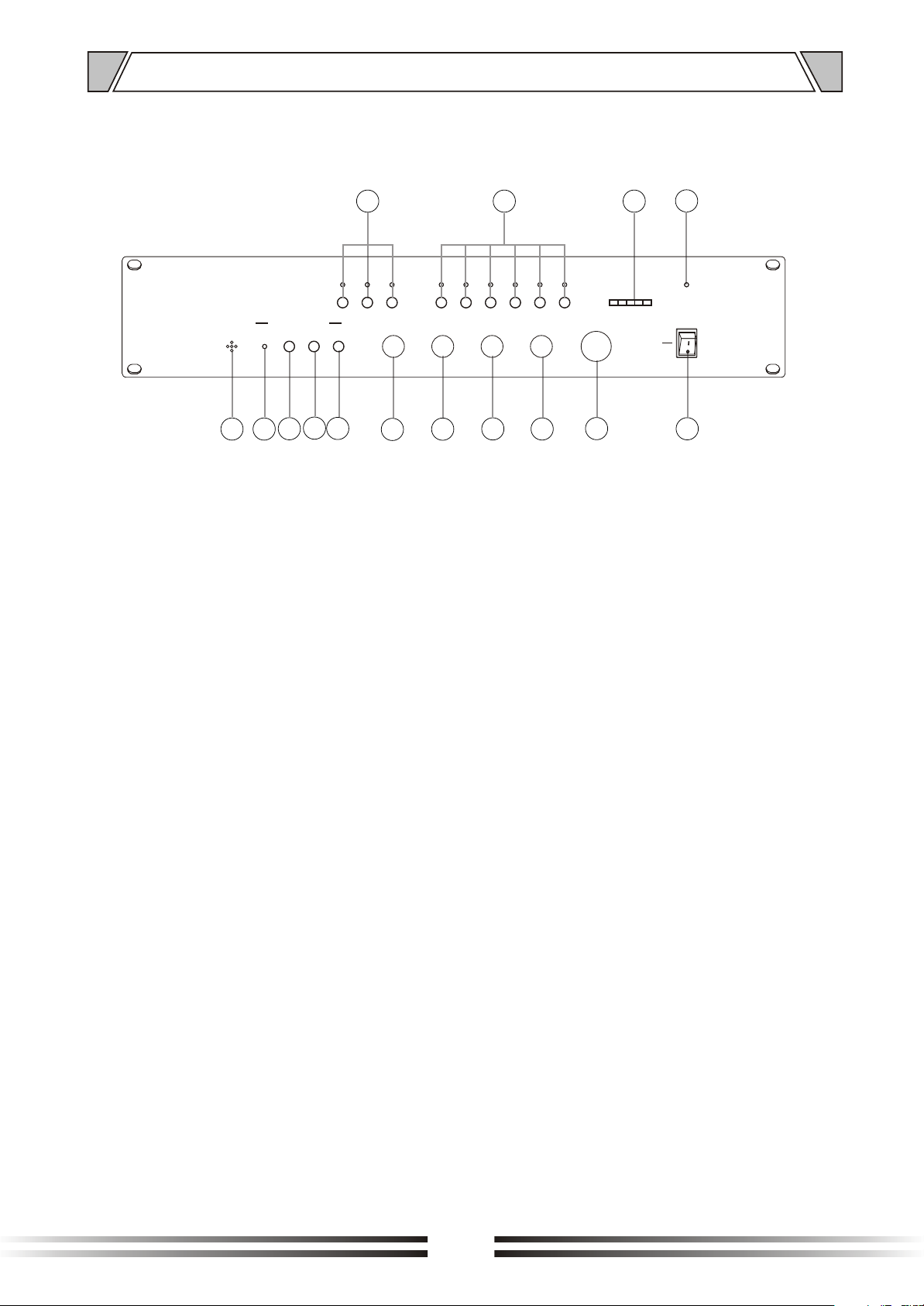
4.1 FRONT PANEL
1
ZONE1
5 5
6 6
7 7
8 8
9 9
10 10
MUSICMICRO
9
15
MESSAGE RECORDER
ACTIVEMIC
13
14
12
RECSTOPPLAY
11
4 4
3 3
2 2
1 1
0 0
10
1. AUDIO
key switch for audio input channel selection:
Tape, CD, Tuner
2. ZONE(1~6)
buttons for music selection In the 6 different zones
3. OUTPUT LEVEL
Signal level indicator
4. POWER
Power indicator
5. POWER SWITCH
On top of the opening Power
Press the end, power shut down
6. MASTER
Master level control
7. TREBLE
Adjust treble response. Rotate clockwise to increase
treble output and anticlockwise to reduce it.
8. BASS
Adjust bass response. Rotate clockwise to increase
bass output and anticlockwise to reduce it.
4
POWER
ON
OFF
5
ZONE2 ZONE3 ZONE4TUNERCDTA PE
-2 -2+2 +2
-4 -4
-6 -6
-8 -8
-10 -10
2
0 0
+4 +4
+6 +6
+8 +8
+10 +10
8
ZONE5
3
ZONE6
7
OUTPUT LEVEL
MASTERBASS TREBLE
5
6
4
3
7
8
2
9
1
0
10
6
9. MUSIC
Music volume control
10.MICRO
Microphone volume control
11.REC
Key switch Rec message
Three messages of 60 seconds each
could be recorded; for message selection
see switch(13) on rear Panel
12.STOP
Key switch stop message
13.PLAY
Key switch play message for manual activation
14.ACTIVE
Indicator play message
15.MIC
Internal microphone for message recording
6
Page 7
NOMENCLATURE AND FUCTIONS
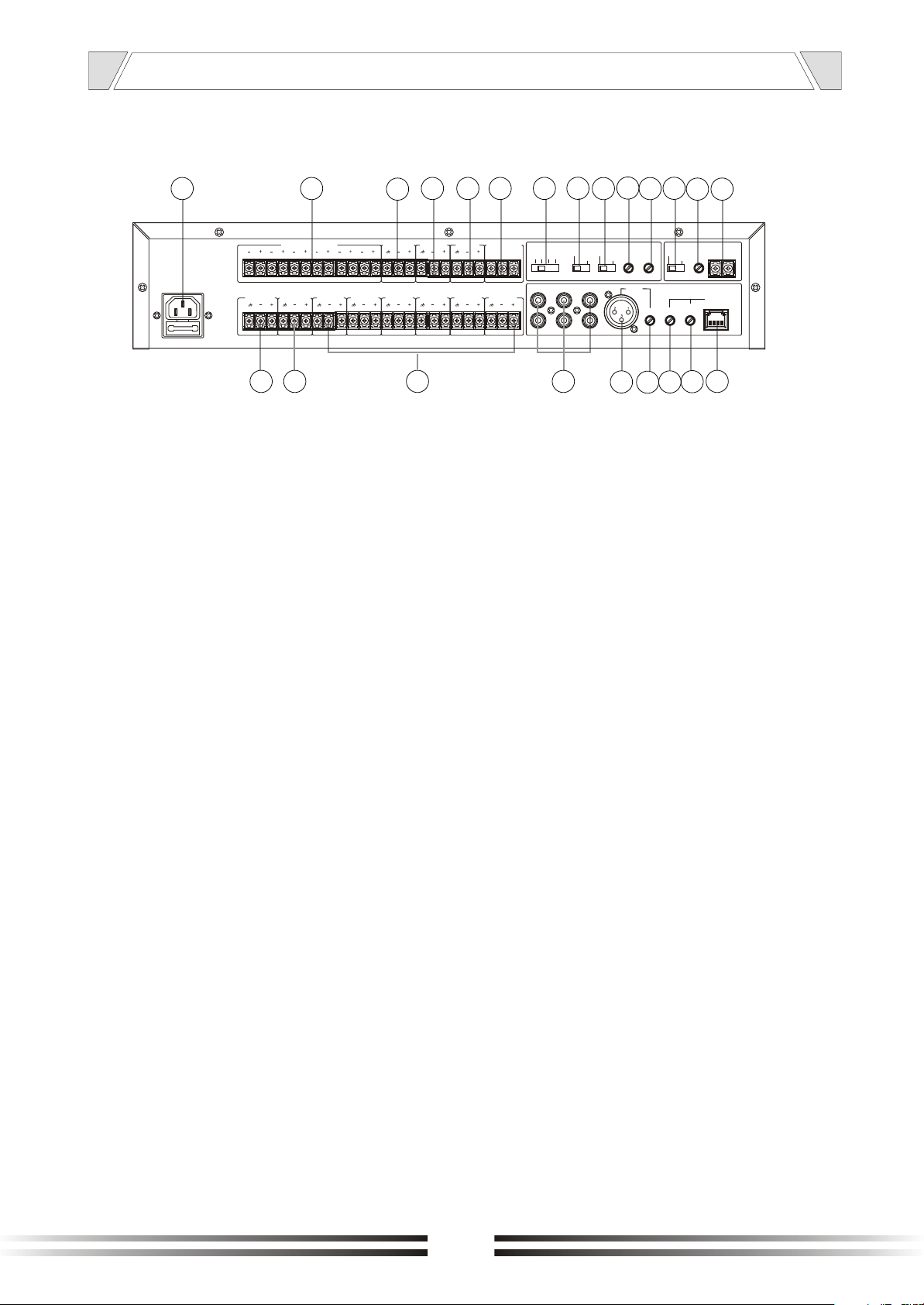
4.2 REAR PANEL
16 17
MIX MUSIC-PAGE OUT
5
~230V 50Hz T1AL 250V
1 2
38
3
37
6
4
16. AC INLET
Connect to the supplied power cord.
17. Strong cut relay control output "alarm
/normal switch" in the alarm state, the
output DC 24 V level
18. Out mix music page voice
19. Out signal music
20. Remote paging output
21. CONTACT PLAY MESSAGE 1 OR 2
The third message is activated by
Microphone base directly.
22.SWITCH REC MESSAGE:
OFF, 1, 2, 3 .
REC MESSAGE switch to 1,2,3,
1,2,3 represent select storage;
When the switch is in the "OFF",
it means not record
23.SWITCH MESSAGE 1
TIME / CONTINUOS
- 1 TIME:
The recorded message plays only
Once
- CONTINUOS:
The recorded message plays
continuously till the message
contact is kept closed.
18
MUSIC OUT
36
19 20 21
PLAY MESSAGE
PAGE OUTRELE ZONE CONSOL OUT
COM NO1 NO2
ZONE 6 OUT ZONE 5 OUT ZONE 4 OUT ZONE 3 OUT ZONE 2 OUT ZONE 1 OUT OPEN RELE ININ COM ZONE
22
REC
MESSAGE
3
TAPE
12
OFF
35
23
MESSAGE
1 TIME
CONTINUOS
CD
242526
ALARM
NORMAL
TUNER
343332
MESSAGE
VOL.REC
MICRO
VOL.PLAY
GAIN GAIN
27
+48V
PHANTOM
28 29
VOLUME
CHIME
MIC
CONSOL
VOLUME
31
PRIORITY
CONSOL
30
24. Switch microphone alarm/normal
the mixer could work without
microphone console BMD6;A simple
microphone base with priority contact
could be connected to XLR microphone
input)
- ALARM:
The voice is simultaneously
distributed in all the 6 zones
- NORMAL:
The voice is distributed only in the
zone selected with front panel
Buttons
25. Volume REC message
26. Volume play message
27. Phantom power select switch
28. Chime volume control
29. Priority control port for BGM and internal chime
30. Remote microphone input interface (RJ 4 5)
31. Remote microphone volume control
32. Remote microphone gain adjustment
33. Local microphone gain adjustment
34. Microphone input XLR balanced
35. Audio source interface
36. OUT ZONE (1~6)
37. Emergency signal input audio source
38
. Background music signal input
7
Page 8
5.OPERATING INSTRUCTIONS
1. When the T-6245 rear panel REC MESSAGE switch to 1,2,3, 1,2,3, respectively, representing the
selected memory, press the T-6245 panel REC button, the indicator (ACTIVE) light from the panel
MIC port input signal to start recording; press the T-6245 panel STOP button to stop recording.
(Each memory can record one minute, store 3 pre-recorded alarm signal can be good when used in
alarm). According to the contents of the recording switch to the REC MESSAGE 1,2,3 position, you
can audition to play the content, press the play button panel, press the stop end.
2. Choose to play one or two storage reservoir playback; were short port PLAY MESSAGE of COM
-NO1/COM-NO2,, indicator (ACTIVE) light, start playing the sound, then you can choose to play one
time, and repeat play disconnect the port to stop playback.
3. Press the T-6245 panel STOP button to stop recording / stop playing the recording; choose T-6245
rear panel MESSAGE 1 TIME / CONTINUOUS represent a record player / continuous play audio;
switch REC MESSAGE to the OFF state, representatives can not be recorded.
4. Under NORMAL (normal operation) state, the T-6245 board IN COM ZONE port input signal, select
the T-6245 panel ZONE1-6 buttons, the T-6245 board ZONE1-6 OUT correspond with output, input
and output 1:1.
5. Three levels of priority function:
built-in recording information (1 and 2) Priority: TUNER, CD, MP3;
Built-in chime priority: Record Information (1 and 2): TUNER, CD, Mp3;
All audio remote call microphone priority: This function is used to "MIX MUSIC / PAGE" output port.
""
""
""
""
""
""
""
""
""
6. Failure to exclude guidance:
Phenomenon
All wires connected
but no voice output
Plugged in, but the alarm signal
No sound output under normal
conditions
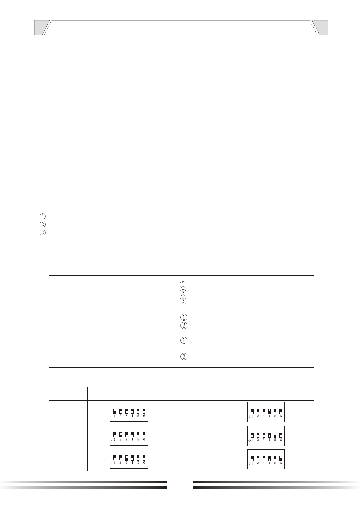
7. ID consol address set
ADDRESS
DEFINITION
1
ON
Reason
no power or wrong plug connection
fuse burned
no input signal
overload or short circuit
voltage is not stable, high or low
The machine is under high
temperature conditions to protect
wire connection error
ADDRESS
DEFINITION
4
ON
2
3
ON
ON
8
5
6
ON
ON
Page 9
6. CONNECTIONS
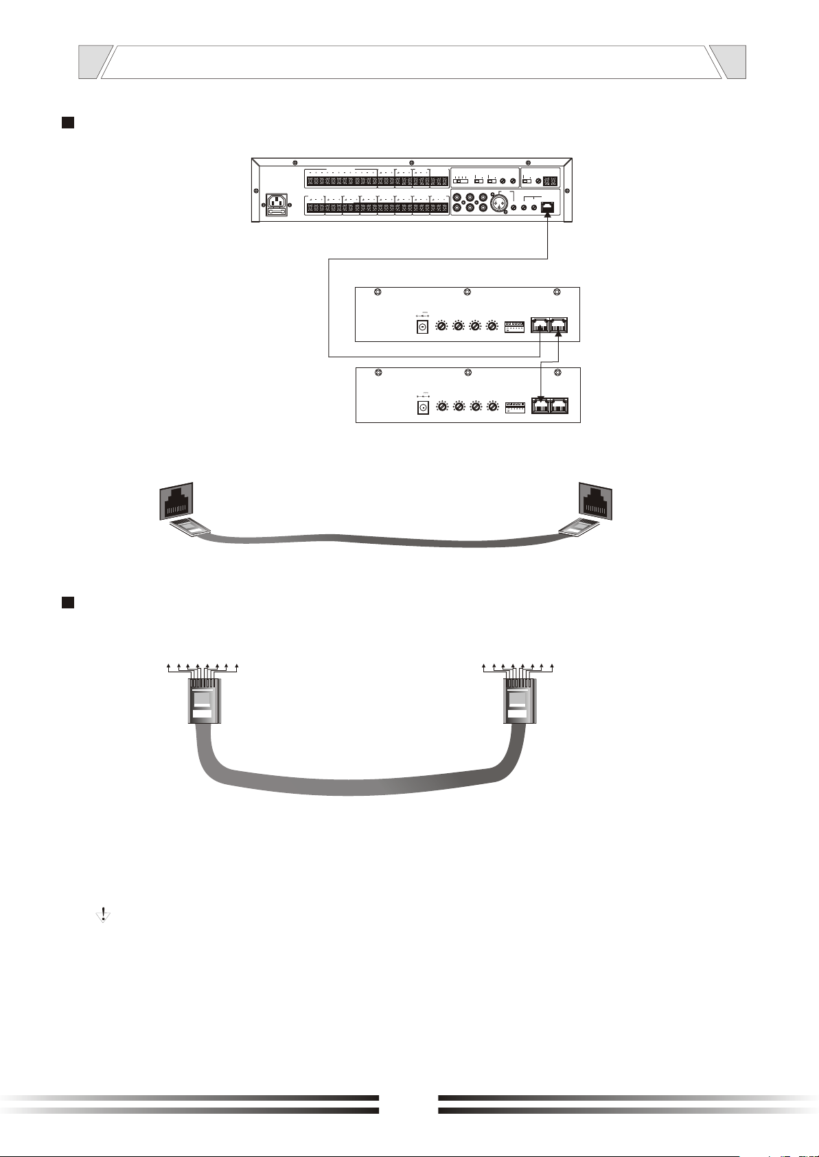
NETWORK CONNECTION LINE
Digital Mixer 6 zone
A
~230V 50Hz T1AL 250V
1 2
MIX MUSIC-PAGE OUT
MUSIC OUT
5
3
6
4
PAGE OUTRELE ZONE CONSOL OUT
Paging Station
DC24V
DC24V
POWER
POWER
COM NO1 NO2
ZONE 6 OUT ZONE 5 OUT ZONE 4 OUT ZONE 3 OUT ZONE 2 OUT ZONE 1 OUT OPEN RELE ININ COM ZONE
1A
1A
PLAY MESSAGE
VOLUME
VOLUME
REC
MESSAGE
MESSAGE
1 TIME
3
OFF
12
CONTINUOS
TUNER
TAPE
CD
BASS
TREBLE
-10 -10+10 +100 010 10
BASS
TREBLE
-10 -10+10 +100 010 10
ALARM
CHIME
VOLUME
CHIME
VOLUME
MESSAGE
VOLUME
+48V
PRIORITY
CHIME
PHANTOM
VOL.PLAY
VOL.REC
MIC
NORMAL
MICRO
CONSOL
CONSOL
GAIN GAIN
VOLUME
A
Network Line
LINE IN
ID CONSOL
ID CONSOL
LINK OUT
B
A
LINE IN
LINK OUT
B
B
NET PRODUCTION LINE METHOD
5
7
4
1 2 3
8
6
A
A: 1 Blue 2 White Blue 3 Brown 4 White Brown 5 Orange 6 White Orange
7 Green 8 White Green
B: 1 Blue 2 White Blue 3 Brown 4 White Brown 5 Orange 6 White Orange
7 Green 8 White Green
Note: Network lines must adopt the five categories of twisted-pair with double-layer
shielding, RJ45 connectors must be used with shielded connector.
1 2 3
5
4
678
B
9
Page 10
7. APPLICATIONS
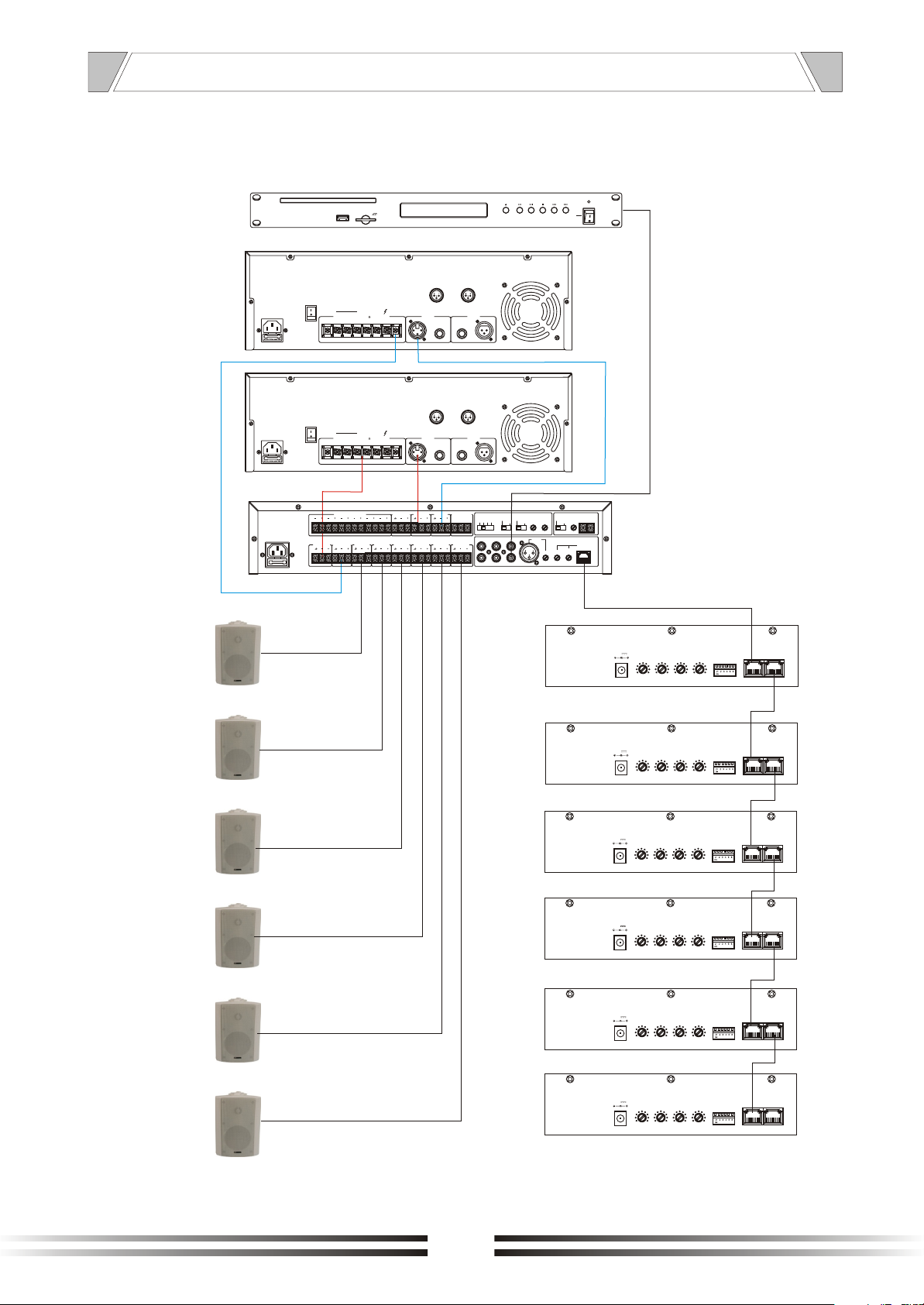
1 amplifier for music 1 amplifier for voice for 6 zone
CD player
USB
INPUTS LINK
XLR BAL
1-GND
2-HOT+
GND
LIFT
GND
LIFT
OUTPUTS
4-16
70V 100V
COM
COM COM
OUTPUTS
4-16
70V 100V
COM
COM COM
3-COLD-
INPUTS LINK
12
3
INPUTS LINK
XLR BAL
1-GND
2-HOT+
3-COLD-
INPUTS LINK
12
3
OPEN/
CLOSE
CD/
USB
/SD
PLAY STOP NEXTPREVIOUS
POWER
ON
OFF
Voice
Music
Zone 1
Zone 2
Zone 3
Zone 4
~230V 50Hz T1AL 250V
1 2
MIX MUSIC-PAGE OUT
5
3
6
4
MUSIC OUT
PLAY MESSAGE
PAGE OUTRELE ZONE CONSOL OUT
COM NO1 NO2
ZONE 6 OUT ZONE 5 OUT ZONE 4 OUT ZONE 3 OUT ZONE 2 OUT ZONE 1 OUT OPEN RELE ININ COM ZONE
REC
MESSAGE
3
TAPE CD
MESSAGE
MESSAGE
VOLUME
+48V
PRIORITY
CHIME
PHANTOM
ALARM
1 TIME
VOL.PLAY
VOL.REC
OFF
12
CONTINUOS
TUNER
MIC
NORMAL
MICRO
CONSOL
CONSOL
GAIN GAIN
VOLUME
POWER
DC24V
1A
VOLUME
POWER
DC24V
1A
VOLUME
POWER
DC24V
1A
VOLUME
POWER
DC24V
1A
VOLUME
BASS
TREBLE
-10 -10+10 +100 010 10
BASS
TREBLE
-10 -10+10 +100 010 10
BASS
TREBLE
-10 -10+10 +100 010 10
BASS
TREBLE
-10 -10+10 +100 010 10
VOLUME
VOLUME
CHIME
VOLUME
CHIME
VOLUME
CHIME
CHIME
ID CONSOL
ID CONSOL
ID CONSOL
ID CONSOL
LINE IN
LINE IN
LINE IN
LINE IN
LINK OUT
LINK OUT
LINK OUT
LINK OUT
Zone 5
Zone 6
10
POWER
DC24V
1A
VOLUME
POWER
DC24V
1A
VOLUME
BASS
TREBLE
-10 -10+10 +100 010 10
BASS
TREBLE
-10 -10+10 +100 010 10
CHIME
VOLUME
CHIME
VOLUME
ID CONSOL
ID CONSOL
LINE IN
LINE IN
LINK OUT
LINK OUT
Page 11
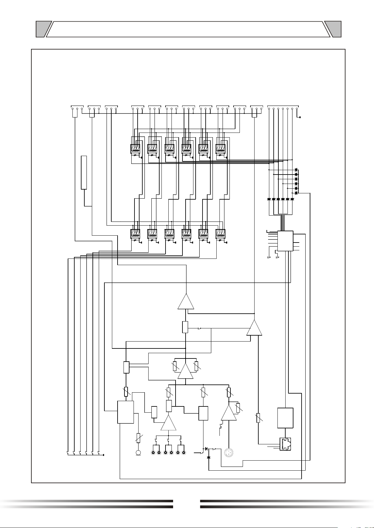
8. BLOCK DIAGRAM
OUT ZONE 6
IN COM ZONE
CONTACT (16)
IN COM ZONE
OUT MUSIC
0 dB
CONTACT (18)
OUT MIX MUSIC-PAGE
COLD
HOT
GND
COLD
HOT
BALANCED
BALANCED
LEVEL OUTPUT (VU METER)
CONTACT (16)
0 dB
CONTACT (17)
COLD
GND
HOT
GND
CONTACT (21)
COLD
HOT
GND
HOT
RL5A
RL6A
OUT RELE'
ZONE CONSOL
CONTACT (15)
OUT ZONE 1
CONTACT (21)
OUT OPEN RELE'
CONTACT (20)
OUT PAGE
0 dB
OUT ZONE 2
OUT ZONE 3
OUT ZONE 4
OUT ZONE 5
COLD
CONTACT (21)
CONTACT (21)
COLD
GND
RL4A
HOT
COLD
GND
HOT
RL3A
CONTACT (21)
CONTACT (21)
COLD
COLD
COLD
HOT
GND
GND
RL1A
RL2A
HOT
HOT
GND
CONTACT (19)
OUT +24 V zone 4
OUT +24 V zone 3
OUT +24 V zone 2
OUT +24 V zone 1
OUT +24 V zone 6
OUT +24 V zone 5
COLD
GND
HOT
GND
BALANCED
OUT -24 V com
1 TIME
RL1B
RL2B
RL3B
RL4B
RL5B
RL6B
A 4
MUTE 4
ON/OFF
MUTE 4
CONTROL ISD4003
ZONE 3
ZONE 6
ZONE 5
ZONE 4
ZONE 2
ZONE 1
MUTE 3
VOLUME
MESSAGE
CONTROL
REC/PLAY
MESSAGE
PLAY
MESSAGE 3
REC
VOLUME
MIC
TREBLE
MUSIC
VOLUME
MUTE 2
MUTE 1
A 1
CD
TUNER
BASS
A 3
CHIME
VOLUME
CHIME
VCC
TAPE
PRIORITY
CONTROL
SIGNAL MESSAGE 1 - 2 - 3
M1
VOLUME
GAIN
A 2
MICRO
PHANTOM
+48V
M1
ALARM
NORMAL
CONTINUOS
123
MCU
OFF
PLAY
PLAY
MESSAGE 1
MESSAGE 2
A 5
CONTROL
VOLUME
8
SIGNAL
1
+24V
POWER
GND
REC
PLAY STOP
OUT VCC
MAX485
CONSOL
11
Page 12
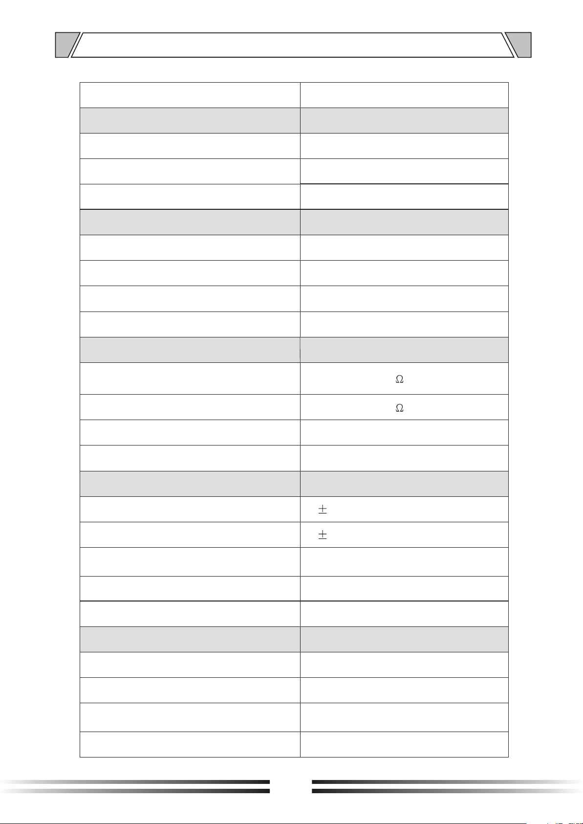
9. SPECIFICATIONS
Model
Consol input
Sensitivity
S/N ratio
Frequency response
1 Mircophone input
Sensitivity
S/N ratio
Frequency response
Phantom power
3 Auxiliary inputs
Tuner and Tape input sensitivity /
impedance
T-6245
350mV
>68dB
50Hz-16KHz(-3dB)
-50/-2dB 5/200 mV
>68dB
50Hz-16KHz(-3dB)
48V
200 mV / 47 K
CD input sensitivity / impedance
S/N ratio
Frequency response
Control
Bass
Treble
Chime
Strong cut relay control output
Normal distortion
Operating condition
Main power supply
Dimension(mm)
500 mV / 47 K
>80 dB
20Hz-16KHz(-3dB)
10dB
10dB
4 tone active for contact free in
priority and BGM
DC 24V
0.1%
~220-240V/ 50/60Hz
484X322X88
Weight
Max number of microphone bases
6Kg
6
12
Page 13
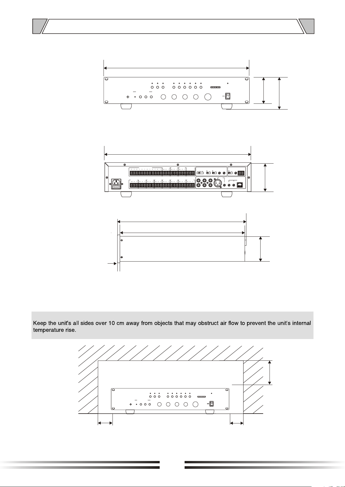
10. DIMENSIONAL DIAGRAM
UNIT :mm
MESSAGE RECORDER
ACTIVEMIC
484
POWER
ZONE5
ZONE2 ZONE3 ZONE4TUNERCDTA PE
ZONE1
MUSICMICRO
5 5
RECSTOPPLAY
6 6
4 4
3 3
7 7
8 8
2 2
9 9
1 1
0 0
10 10
0 0
-2 -2+2 +2
-4 -4
+4 +4
-6 -6
+6 +6
-8 -8
+8 +8
-10 -10
+10 +10
OUTPUT LEVEL
ZONE6
MASTERBASS TREBLE
5
6
4
3
7
ON
8
2
1
OFF
9
0
10
88
94
436
6
~230V 50Hz T1AL 250V
1 2
MIX MUSIC-PAGE OUT
5
3
6
4
MUSIC OUT
PLAY MESSAGE
PAGE OUTRELE ZONE CONSOL OUT
COM NO1 NO2
ZONE 6 OUT ZONE 5 OUT ZONE 4 OUT ZONE 3 OUT ZONE 2 OUT ZONE 1 OUT OPEN RELE ININ COM ZONE
REC
MESSAGE
MESSAGE
VOLUME
+48V
MESSAGE
ALARM
1 TIME
3
TAPE
VOL.REC
OFF
12
CONTINUOS
NORMAL
TUNER
CD
MICRO
VOL.PLAY
GAIN GAIN
PRIORITY
CHIME
PHANTOM
MIC
CONSOL
CONSOL
VOLUME
84
322
316
84
UNIT :mm
Over
ACTIVEMIC
100
MESSAGE RECORDER
ZONE1
MUSICMICRO
5 5
RECSTOPPLAY
6 6
4 4
3 3
7 7
8 8
2 2
9 9
1 1
0 0
10 10
0 0
-2 -2+2 +2
-4 -4
+4 +4
-6 -6
+6 +6
-8 -8
+8 +8
-10 -10
+10 +10
ZONE6
MASTERBASS TREBLE
5
6
4
3
7
ON
8
2
OFF
9
1
0
10
Over
100
Over
100
POWER
OUTPUT LEVEL
ZONE5
ZONE2 ZONE3 ZONE4TUNERCDTAPE
13
Page 14

PUBLIC ADDRESS SYSTEM
VersionV0.2
 Loading...