

Page 1
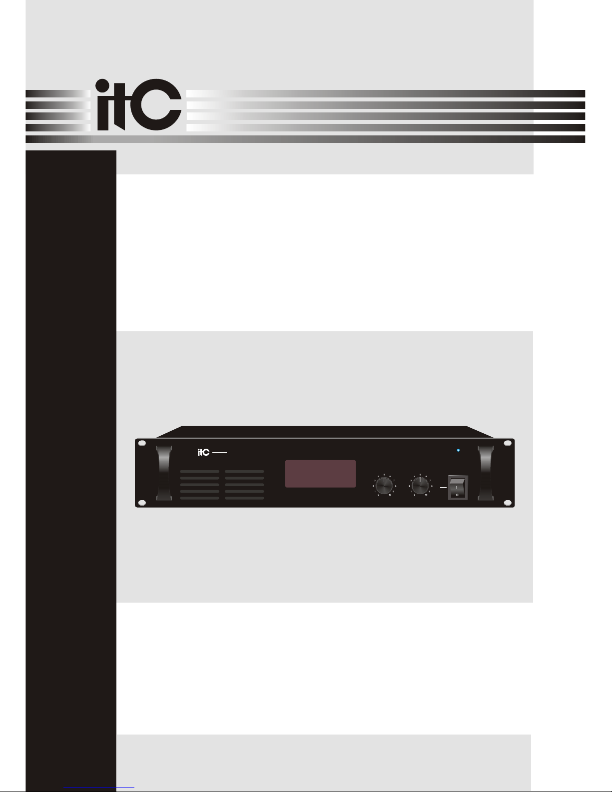
Please follow the instructions in this manual to obtain the optimum results from this unit.
We also recommend that you keep this manual handy for future reference.
MONITOR
OPERATION MANUAL
T-6204
PUBLIC ADDRESS SYSTEM
ON
POWER
OFF
MONITOR CHANNEL
CH1 CH2
CH3
CH4 CH5 CH6 CH7 CH8 CH9 CH10
+24dB
+18dB
+12dB
+6dB
0dB
T-6204
MONITOR
Page 2

TABLE OF CONTENTS
1. SAFETY PRECAUTIONS .......................................................................................3
2. GENERAL DESCRIPTION ....................................................................................5
3. FEATURES ...............................................................................................................5
4. NOMENCLATURE AND FUNCTIONS
4.1 Front Panel ..............................................................................................................6
4.2 Rear Panel.............................................................................................................. 7
5. .........................................................................................8
6. APPLICATIONS .......................................................................................................9
7.SPECIFICATIONS ................................................................................................. 10
8.DIMENSIONAL DIAGRAM ....................................................................................11
MACHINE OPERATION
2
Page 3
Be sure to read the instructions in this section carefully before use.
Make sure to observe the instructions in this manual as the conventions of safety symbols and messages
regarded as very important precautions are included.
We also recommend you keep this instruction manual handy for future reference.
Safety Symbol and Message Conventions
Safety symbols and messages described below are used in this manual to prevent bodily injury and property
damage which could result from mishandling. Before operating your product, read this manual first and
understand the safety symbols and messages so you are thoroughly aware of the potential safety
Indicates a potentially hazardous situation which, if mishandled, could
result in death or serious personal injury.
Indicates a potentially hazardous situation which, if mishandled, could
result in moderate or minor personal injury, and/or property damage.
When Installing the Unit
Do not expose the unit to rain or an environment
where it may be splashed by water or other liquids,
as doing so may result in fire or electric shock.
Use the unit only with the voltage specified on the
unit. Using a voltage higher than that which is
specified may result in fire or electric shock.
Do not cut, kink, otherwise damage nor modify the
power supply cord. In addition, avoid using the
power cord in close proximity to heaters, and never
place heavy objects -- including the unit itself -- on
the power cord, as doing so may result in fire or
electric shock.
Be sure to replace the unit's terminal cover after
connection completion. Because high voltage is
applied to the speaker terminals, never touch these
terminals to avoid electric shock.
Be sure to ground to the safety ground (earth)
terminal to avoid electric shock. Never ground to a
gas pipe as a catastrophic disaster may result.
Avoid installing or mounting the unit in unstable
locations, such as on a rickety table or a slanted
surface. Doing so may result in the unit falling
down, causing personal injury and/or property
damage.
When the Unit is in Use
Should the following irregularity be found during
use, immediately switch off the power, disconnect
the power supply plug from the AC outlet and
contact your nearest dealer. Make no further
attempt to operate the unit in this condition as this
may cause fire or electric shock.
If you detect smoke or a strange smell coming
from the unit.
If water or any metallic object gets into the unit
If the unit falls, or the unit case breaks
If the power supply cord is damaged (exposure of
the core, disconnection, etc.)
If it is malfunctioning (no tone sounds.)
To prevent a fire or electric shock, never open nor
remove the unit case as there are high voltage
components inside the unit. Refer all servicing to
your nearest dealer.
ITC
ITC
Do not place cups, bowls, or other containers of
liquid or metallic objects on top of the unit. If they
accidentally spill into the unit, this may cause a fire
or electric shock.
Do not insert nor drop metallic objects or
flammable materials in the ventilation slots of the
unit's cover, as this may result in fire or electric
shock.
1. SAFETY PRECAUTIONS
3
Page 4
An all-pole mains switch with a contact separation of at least 3 mm in each pole shall be incorporated in
the electrical installation of the building.
When Installing the Unit
Never plug in nor remove the power supply plug
with wet hands, as doing so may cause electric
shock.
When unplugging the power supply cord, be sure
to grasp the power supply plug; never pull on the
cord itself. Operating the unit with a damaged
power supply cord may cause a fire or electric
shock.
When moving the unit, be sure to remove its power
supply cord from the wall outlet. Moving the unit
with the power cord connected to the outlet may
cause damage to the power cord, resulting in fire or
electric shock. When removing the power cord, be
sure to hold its plug to pull.
Do not block the ventilation slots in the unit's cover.
Doing so may cause heat to build up inside the unit
and result in fire.
Avoid installing the unit in humid or dusty locations,
in locations exposed to the direct sunlight, near the
heaters, or in locations generating sooty smoke or
steam as doing otherwise may result in fire or
electric shock.
When the Unit is in Use
Do not place heavy objects on the unit as this may
cause it to fall or break which may result in
personal injury and/or property damage. In
addition, the object itself may fall off and cause
injury and/or damage.
Make sure that the volume control is set to
minimum position before power is switched on.
Loud noise produced at high volume when power is
switched on can impair hearing.
Do not operate the unit for an extended period of
time with the sound distorting. This is an indication
of a malfunction, which in turn can cause heat to
generate and result in a fire.
Contact your dealer as to the cleaning. If dust
is allowed to accumulate in the unit over a long
period of time, a fire or damage to the unit may
result.
ITC
If dust accumulates on the power supply plug or in
the wall AC outlet, a fire may result. Clean it
periodically. In addition, insert the plug in the wall
outlet securely.
Switch off the power, and unplug the power supply
plug from the AC outlet for safety purposes when
cleaning or leaving the unit unused for 10 days or
more. Doing otherwise may cause a fire or electric
shock.
1. SAFETY PRECAUTIONS
4
Page 5

3. FEATURES
2. GENERAL DESCRIPTION
=Monitor 10 speaker zones.
=Independently select level meter.
=Build-in speaker, wide frequency speaker, rich and accurate voices.
=Adjustable monitoring volume.
The T-6204 is a 10 channel monitor panel that works with and monitor T-6202 speaker selector's zone output,
also this units can make sure the background music and paging system out of the control room is strictly under
control.
5
Page 6
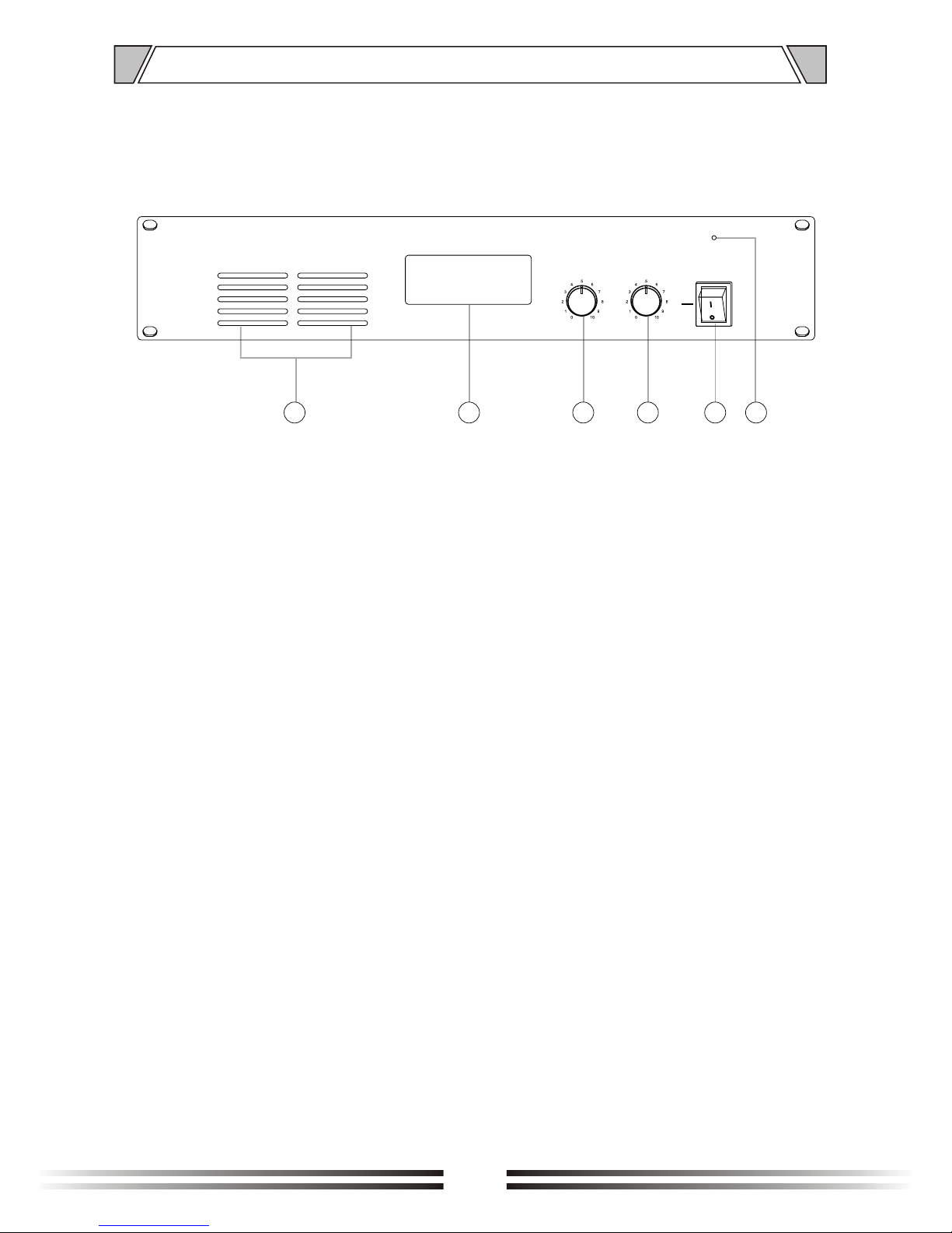
1. FANNER
2. CH1~CH10
LED level meter
3. MONITOR
Volume control
4. CHANNEL
CH Selecting switch
4. NOMENCLATURE AND FUNCTIONS
31 6
4.1 FRONT PANEL
4 52
6
ON
POWER
OFF
MONITOR CHANNEL
CH1 CH2
CH3
CH4 CH5 CH6 CH7 CH8 CH9 CH10
+24dB
+18dB
+12dB
+6dB
0dB
6. POWER
Power indicator
5. POWER SWITCH
On top of the opening Power
Press the end, power shut down
Page 7
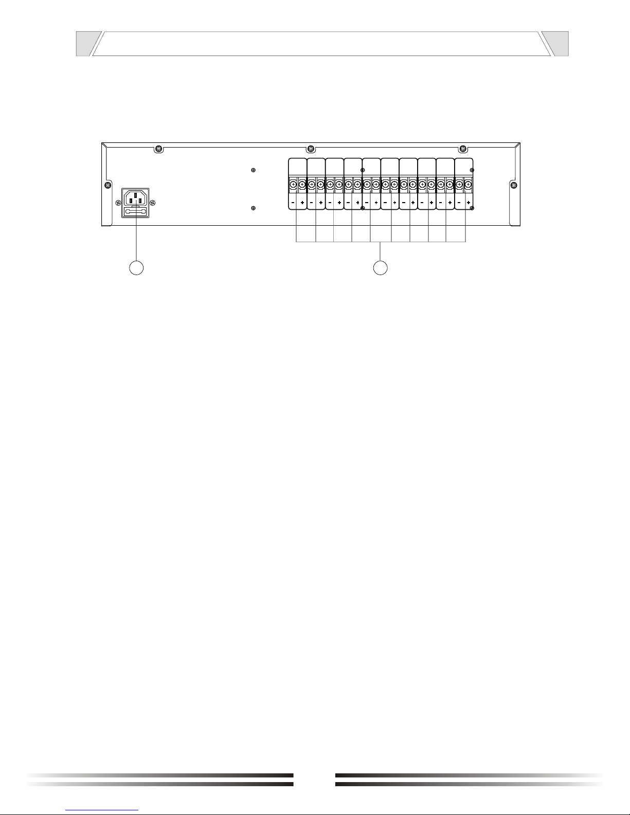
NOMENCLATURE AND FUCTIONS
7.~220-240V 50/60HzPOWER INPUT
4.2 REAR PANEL
87
7
CH 1 CH 2
CH 3
CH 4 CH 5 CH 6 CH 7 CH 8 CH 9 CH 10
8. (CH1~CH10) INPUT
(CH1~CH10) monitor speaker zones
Page 8

5. MACHINE OPERATION
1 Patch cord system connection, switch in power.
2 Made out of monitor gangway pick switch "SELECTOR" ,
Pick post monitor gangway, speaker play back gangway
sound, level meter as well display gangway or level.
3 monitor sound volume practicable prep flavoring coordination.
8
Page 9
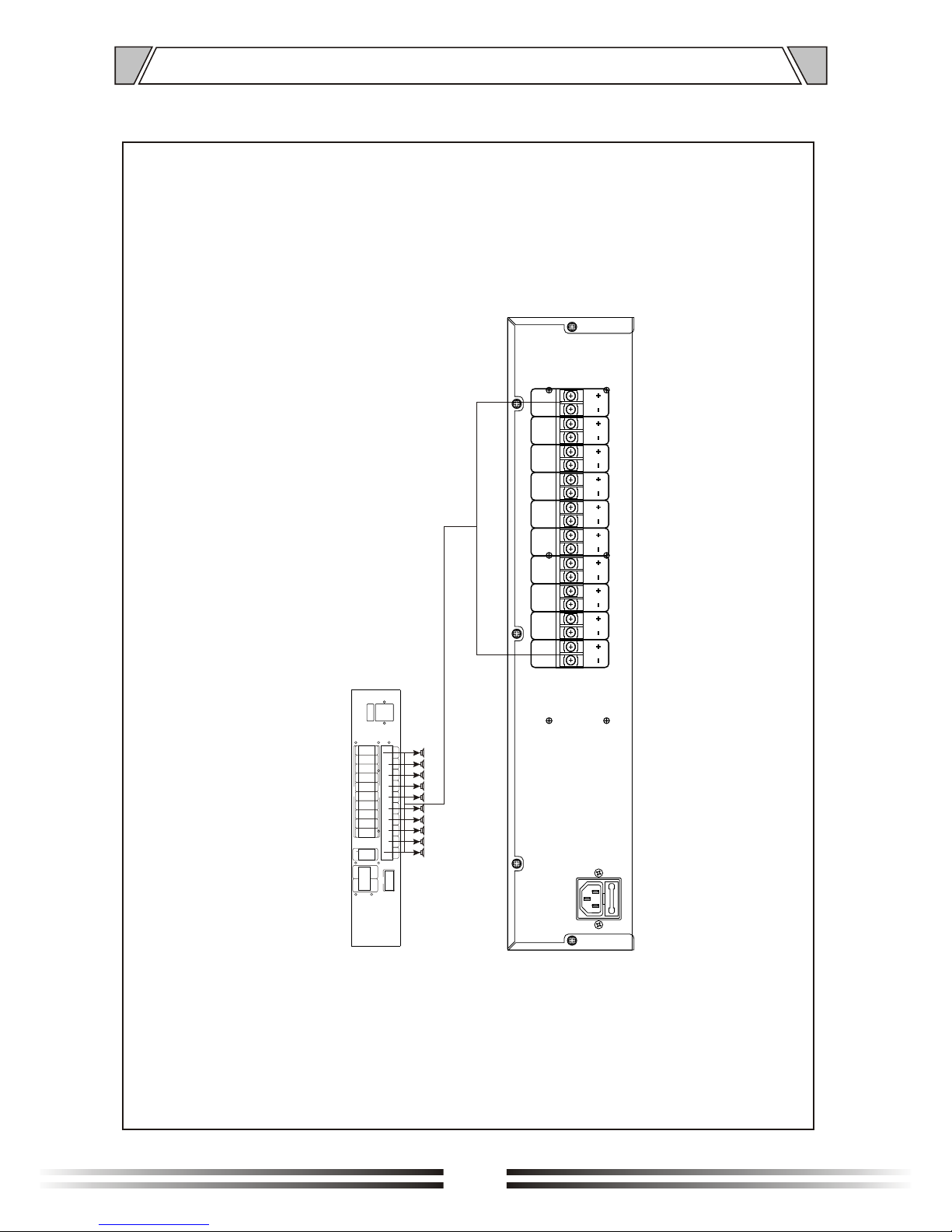
6. APPLICATIONS
REAR PANEL CONNECTIONS
SPEAKER SELECTORS
COM
INPUT A
+
INPUT B
+
ALARM A
+
ALARM B
+ CH 1 - + CH 3 - + C H 4 - + CH 5 - + CH 6 - + CH 7 - + CH 8 - + CH 9 - + CH 1 0 -+ CH 2 -
+ 1 - + 2 - + 3 - + 4 - + 5 - + 6 - + 7 - + 8 - + 9 - + 1 0 -
ALARM IN
+ 1 - + 2 - + 3 - + 4 - + 5 - + 6 - + 7 - + 8 - + 9 - + 1 0 -
ALARM OUT
~220-240V 50/60Hz
T1AL250V
SPEAKER
9
CH 1 CH 2
CH 3
CH 4 CH 5 CH 6 CH 7 CH 8 CH 9 CH 10
Page 10
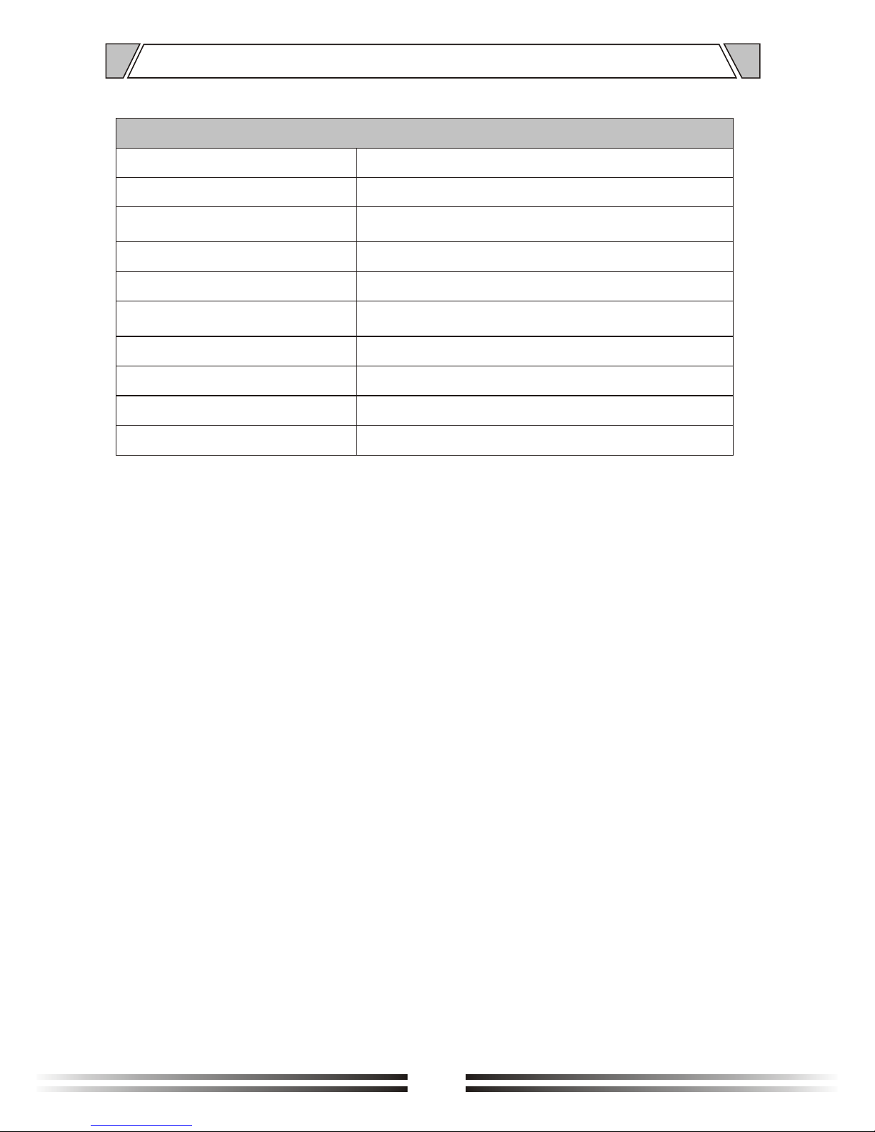
7.SPECIFICATIONS
MODEL
MONITOR PANELMONITOR PANEL
T-6204
SPEAKER ZONES
INDICATORS
POWER REQUIREMENTS
DIMENSIONS(MM)
CONTROL
PROTECTION
POWER CONSUMPTION
NET WEIGHT
484X368X88
~220-240V 50/60Hz
Individual zone selectors power switch
AC fuse,1A
30W
5.2Kg
10
Power LED,Level meter
4Kg
GROSS WEIGHT
10
Page 11
100
Over
100
Over
Over
100
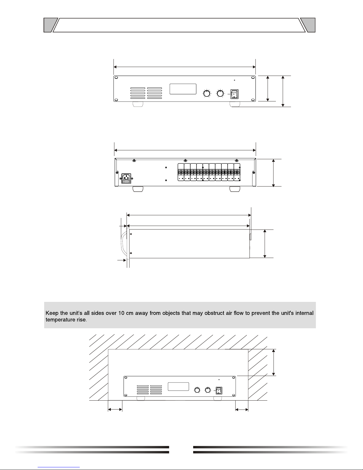
8. DIMENSIONAL DIAGRAM
UNIT :mm
6
84
84
25
339
333
88
94
436
484
UNIT :mm
11
ON
POWER
OFF
MONITOR CHANNEL
CH1 CH2
CH3
CH4 CH5 CH6 CH7 CH8 CH9 CH10
+24dB
+18dB
+12dB
+6dB
0dB
CH 1 CH 2
CH 3
CH 4 CH 5 CH 6 CH 7 CH 8 CH 9 CH 10
ON
POWER
OFF
MONITOR CHANNEL
CH1 CH2
CH3
CH4 CH5 CH6 CH7 CH8 CH9 CH10
+24dB
+18dB
+12dB
+6dB
0dB
Page 12

PUBLIC ADDRESS SYSTEM
VersionV0.1
 Loading...