

Page 1
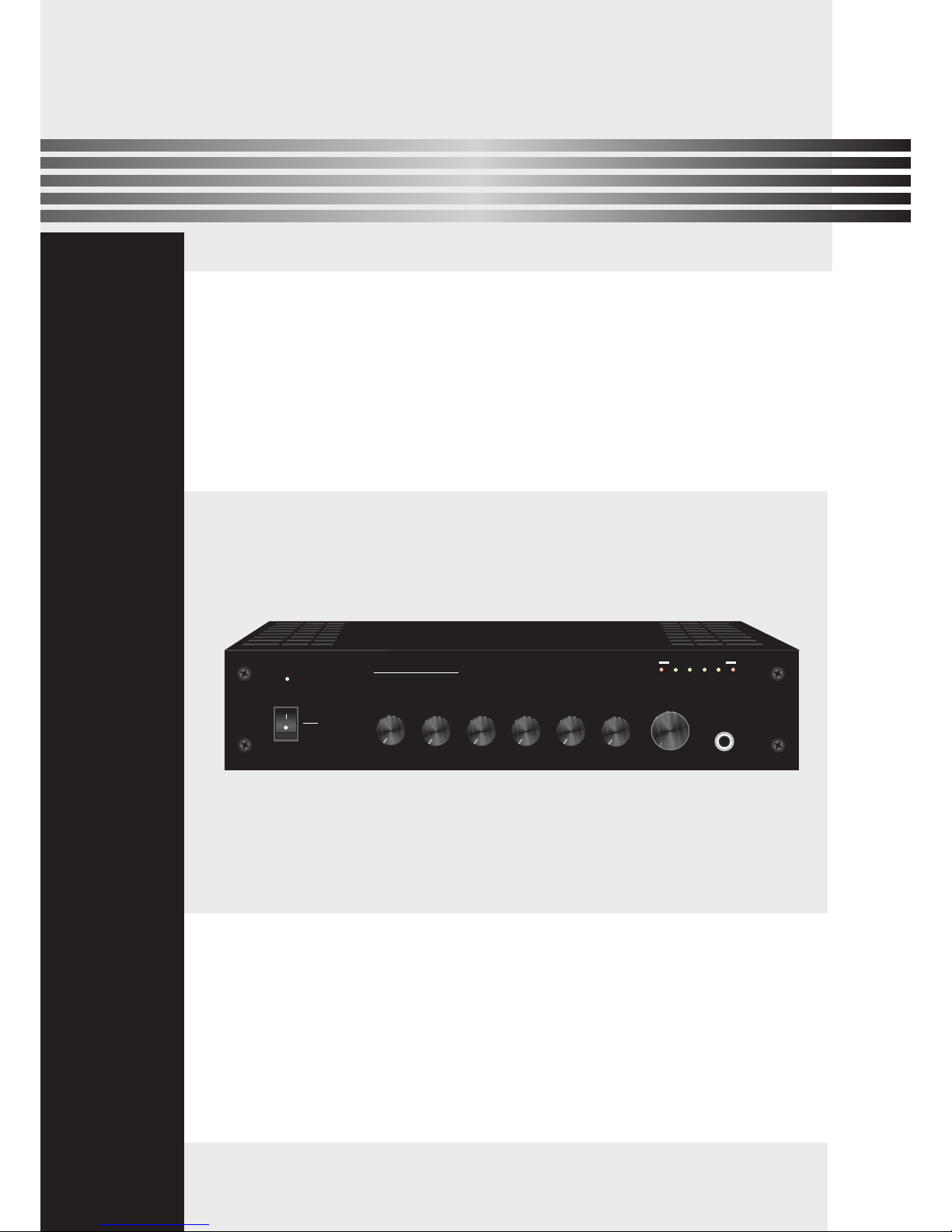
Please follow the instructions in this manual to obtain the optimum results from this unit.
We also recommend that you keep this manual handy for future reference.
MIXER AMPLIFIER
T-40AP
OPERATION MANUAL
PUBLIC ADDRESS SYSTE M
ON
OFF
BASS
-5
0
-1
-2
-3
-4
+1
+2
+3
+4
+5
TREBLE
-5
0
-1
-2
-3
-4
+1
+2
+3
+4
+5
0
1
2
3
4
5
6
7
8
9
10
MIC2
TEL
0
1
2
3
4
5
6
7
8
9
10
POWER
0
1
2
3
4
5
6
7
8
9
10
MIC1
AUX
0
1
2
3
4
5
6
7
8
9
10
5
0
1
2
3
4
6
7
8
9
10
MASTER
MIC1
INPUT
OUTPUT LEVEL
246 8 10
PROT
T-40AP
MIXER AMPLIFIER
Page 2

2
TABLE OF CONTENTS
1. SAFETY PRECAUTIONS .. .......... ............. .......... .......... ............. .......... .......... .........3
2. FEATURES .......... .......... .......... ... .......... .......... .......... ... .......... .......... .......... ... .......... ..5
3. NOMENCLATURE AND FUNCTIONS
3.1 Front Panel .. .......... ... .......... .......... .......... ... .......... .......... ............. .......... .......... ....... 6
3.2 Rea r Pan el........ .......... .......... ............. .......... .......... ... .......... .......... .......... ... .......... ...7
4. CONNECTIONS
4.1. Sp eak er Connec tio ns ......... .......... .......... ... .......... .......... .......... ... .......... .......... ........8
4.2. XL R Con nection s ... .......... .......... ............. .......... .......... ............. .......... .......... ........ 8
5.MACHINE OPERATION ...... ... .......... .......... .......... ... .......... .......... ............. .......... ......9
6.APPLICATIONS .... .......... .......... ............. .......... .......... ............. .......... .......... ... .......... 10
7. BLOCK DIAGRAM..... .......... .......... ... .......... .......... .......... ... .......... .......... .......... ... .... 11
8.SPECIFICATIONS ... .......... .......... ... .......... .......... ............. .......... .......... ............. ......12
9.DIMENSIONAL DIAGRAM . .......... ... .......... .......... .......... ... .......... .......... .......... ... ....13
Page 3
Be sure to read the instructions in this section carefully before use.
Make sure to observe the instructions in this manual as the conventions of safety symbols and messages
regarded as very important precautions are included.
We also recommend you keep this instruction manual handy for future reference.
Safety Symbol and Message Conventions
Safety symbols and messages described below are used in this manual to prevent bodily injury and property
damage which could result from mishandling. Before operating your product, read this manual first and
understand the safety symbols and messages so you are thoroughly aware of the potential safety
Indicates a potentially hazardous situation which, if mishandled, could
result in death or serious personal injury.
Indicates a potentially hazardous situation which, if mishandled, could
result in moderate or minor personal injury, and/or property damage.
When Installing the Unit
Do not expose the unit to rain or an environment
where it may be splashed by water or other liquids,
as doing so may result in fire or electric shock.
Use the unit only with the voltage specified on the
unit. Using a voltage higher than that which is
specified may result in fire or electric shock.
Do not cut, kink, otherwise damage nor modify the
power supply cord. In addition, avoid using the
power cord in close proximity to heaters, and never
place heavy objects -- including the unit itself -- on
the power cord, as doing so may result in fire or
electric shock.
Be sure to replace the unit's terminal cover after
connection completion. Because high voltage is
applied to the speaker terminals, never touch these
terminals to avoid electric shock.
Be sure to ground to the safety ground (earth)
terminal to avoid electric shock. Never ground to a
gas pipe as a catastrophic disaster may result.
Avoid installing or mounting the unit in unstable
locations, such as on a rickety table or a slanted
surface. Doing so may result in the unit falling
down, causing personal injury and/or property
damage.
When the Unit is in Use
Should the following irregularity be found during
use, immediately swh off the power, disconnect
the power supply plug from the AC outlet and
contact your nearest dealer . Make no further
attempt to operate the unit in this condition as this
may cause fire or electric shock.
If you detect smoke or a strange smell coming
from the unit.
If water or any metallic object gets into the unit
If the unit falls, or the unit case breaks
If the power supply cord is damaged (exposure of
the core, disconnection, etc.)
If it is malfunctioning (no tone sounds.)
To prevent a fire or electric shock, never open nor
remove the unit case as there are high voltage
components inside the unit. Refer all servicing to
your nearest dealer.
Do not place cups, bowls, or other containers of
liquid or metallic objects on top of the unit. If they
accidentally spill into the unit, this may cause a fire
or electric shock.
Do not insert nor drop metallic objects or
flammable materials in the ventilation slots of the
unit's cover, as this may result in fire or electric
shock.
3
1. SAFETY PRECAUTIONS
Page 4
An all-pole mains swh with a contact separation of at least 3 mm in each pole shall be incorporated in
the electrical installation of the building.
When Installing the Unit
Never plug in nor remove the power supply plug
with wet hands, as doing so may cause electric
shock.
When unplugging the power supply cord, be sure
to grasp the power supply plug; never pull on the
cord itself. Operating the unit with a damaged
power supply cord may cause a fire or electric
shock.
When moving the unit, be sure to remove its power
supply cord from the wall outlet. Moving the unit
with the power cord connected to the outlet may
cause damage to the power cord, resulting in fire or
electric shock. When removing the power cord, be
sure to hold its plug to pull.
Do not block the ventilation slots in the unit's cover.
Doing so may cause heat to build up inside the unit
and result in fire.
Avoid installing the unit in humid or dusty locations,
in locations exposed to the direct sunlight, near the
heaters, or in locations generating sooty smoke or
steam as doing otherwise may result in fire or
electric shock.
When the Unit is in Use
Do not place heavy objects on the unit as this may
cause it to fall or break which may result in
personal injury and/or property damage. In
addition, the object itself may fall off and cause
injury and/or damage.
Make sure that the volume control is set to
minimum position before power is swhed on.
Loud noise produced at high volume when power is
swhed on can impair hearing.
Do not operate the unit for an extended period of
time with the sound distorting. This is an indication
of a malfunction, which in turn can cause heat to
generate and result in a fire.
Contact your dealer as to the cleaning. If dust is
allowed to accumulate in the unit over a long
period of time, a fire or damage to the unit may
result.
If dust accumulates on the power supply plug or in
the wall AC outlet, a fire may result. Clean it
periodically. In addition, insert the plug in the wall
outlet securely.
Swh off the power, and unplug the power supply
plug from the AC outlet for safety purposes when
cleaning or leaving the unit unused for 10 days or
more. Doing otherwise may cause a fire or electric
shock.
4
SAFETY PRECAUTIONS
Page 5

5
2. FEATURES
1. Rate d Power:40W.
2. 100V,70V con stant voltag e outputs and 4~ 16Ohms const ant resistan ce output.
3. 1 chan nel MIC2 one-p ort input (5mv 1 Kohms) and 1 cha nnel (300mv 10 Kohms) AUX inpu t
4. 1 chan nel MIC1 balan ced/unbala nced input (2. 5/5mv 1/2Koh ms)
5. 1 chan nel TEL input (se nsitivity 1V 2 Kohms)
6. buil t-in treble ba ss adjusting(b ass ±10dB at 100H z,treble ±10dB at 1 0KHz)
7. buil t-in priorit y fun ctions, TEL pri ority:Tel over ride Aux and MIC( 1-2),MIC1 is s econdprior ity,
overr ide AUX and MIC2 si gnal except te l sig nal.
Page 6
ON
OFF
BASS
-5
0
-1
-2
-3
-4
+1
+2
+3
+4
+5
TREBLE
-5
0
-1
-2
-3
-4
+1
+2
+3
+4
+5
0
1
2
3
4
5
6
7
8
9
10
MIC2
TEL
0
1
2
3
4
5
6
7
8
9
10
POWER
0
1
2
3
4
5
6
7
8
9
10
MIC1
AUX
0
1
2
3
4
5
6
7
8
9
10
5
0
1
2
3
4
6
7
8
9
10
MASTER
MIC1
INPUT
OUTPUT LEVEL
2
4
6 8 10
PROT
6
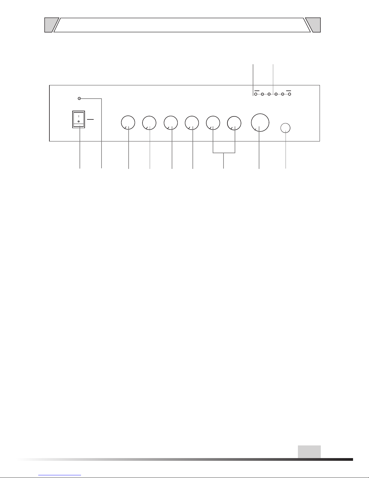
3.1 FRO NT PANEL
1. POWER SWITCH
On top of the opening Power
Press the end, power shut down
2. POWER
Power indicator
3. BASS
Adjust bass response. Rotate clockwise to increase
bass output and anticlockwise to reduce it.
4. TREBLE
Adjust treble response. Rotate clockwise to increase
treble output and anticlockwise to reduce it.
5. AUX
AUX volume control
3. NOMENCLATURE AND FUNCTIONS
6. TEL
TEL volume control
7. MIC1 \MIC2
MIC volume control (MIC1/MIC2)
8. MASTER
Master volume control
9. MIC1 INPUT
MIC1 input 6.3 Microphone jack input
10. LEVEL INDICATORS
Level meters 6 output level indicators
11. PROT
Protection indicator
1 2 3
4
5
6
10
11
7
98
Page 7
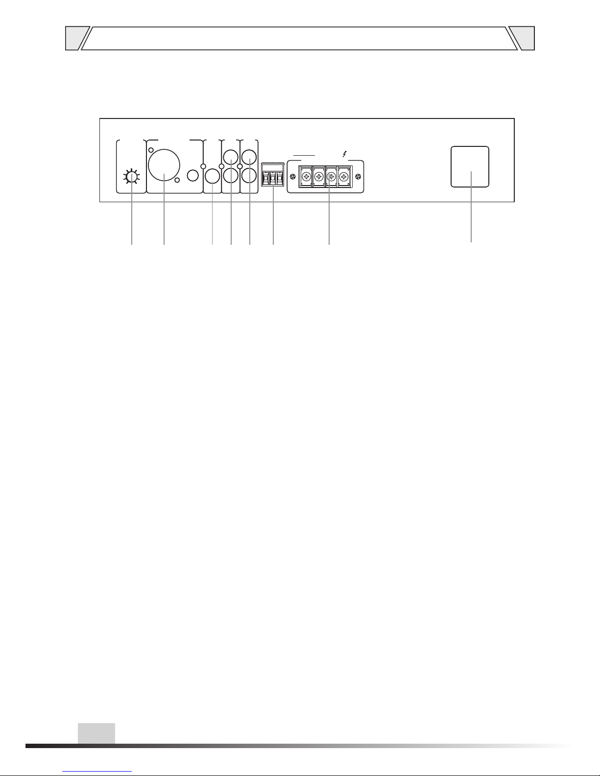
COM 4-16Ω 70 V 100V
OUT PUT
TEL INPUT
G
-
+
LINE
OUT
AUX
MIC 2
MIC 1
INTERRU PT
TIME
A D J
MIC 1
XLR/6.3 0 INPUT
BAL / UNBAL
+48V
PHANTOM
7
NOMENCLATURE AND FUNCTIONS
3.2 REA R PANEL
12. MUT E ADJUS TOR
Adjust t he mu te degree f rom 0 20dB wh en MI C1 input ov err ide all
the oth er in puts.
13. MIC I NPUT WITH PHAN TOM POWER
MIC1 in put c ompatib le of X LR and
6.3 MIC
14. MIC 2 M IC in put
MIC2 in put o f 6.3 MIC
AUX inp ut
AUX for e xtr a equipme nts i nput
15.
16. TEL INPUT
Line ou tpu t
onnec t to other audio p rocessing
equip ments
18.
17.
C
SPEAK ER TERMINALS
Conne cto rs for 4-16 o hms o r 70V and 100 V
speak er
19.~2 20V-240V 50/6 0Hz POWER INPU T
12 13 14 15 16 17 18 19
Page 8
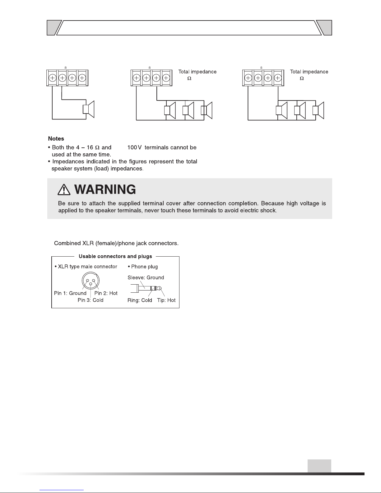
8
70V 1 00V
COM 4 -16
70V 1 00V
COM 4 -16
( )T-40A P
250
100 V LINE
70V 1 00V
COM 4 -16
( )T-40A P
123
70V L INE
4.1 SPE AKER CONNECT ION S
4.2 XLR C ONN ECTIONS
4-1 6Ω
4. CONNECTIONS
70V/
Page 9
1. Tel has priority over all inputs.
2. MIC 1 is second priority, adjust mute electric
potential can override other input signal except
tel signal.
3. It is the same level of MIC 1, when one of the
two port connect with MIC, another conn ect
MIC port is in vain.
MUTE FUNCTION
1 Machi ne is in protect ion
condi tion in case of hi gh
tempe rature
2 Wron g wire connect ion
OPERATION ATTENTION
The four output connectors only can choose two
connectors work together. If voltage is 70V/100V,
the speakers must be with transformer and make
sure the total power wattage of speaker is 15%
less than the power wattage of amplifier.
GUIDANCE OF EXCLUDING ERRORS
No voic e output in
norma l condition
All the w ires are
conne cted well
but no vo ice output
Cause
1 No powe r or wrong
plug co nnection
2 Fuse is b urned
3 Volume i s town off
4 No inpu t signal
Power o n but alarming s ignal
1 Overl oading or shor t
circu it
2 Voltag e is not stable,
too hig h or low
Pheno mena
5. MACHINE OPERATION
9
Page 10
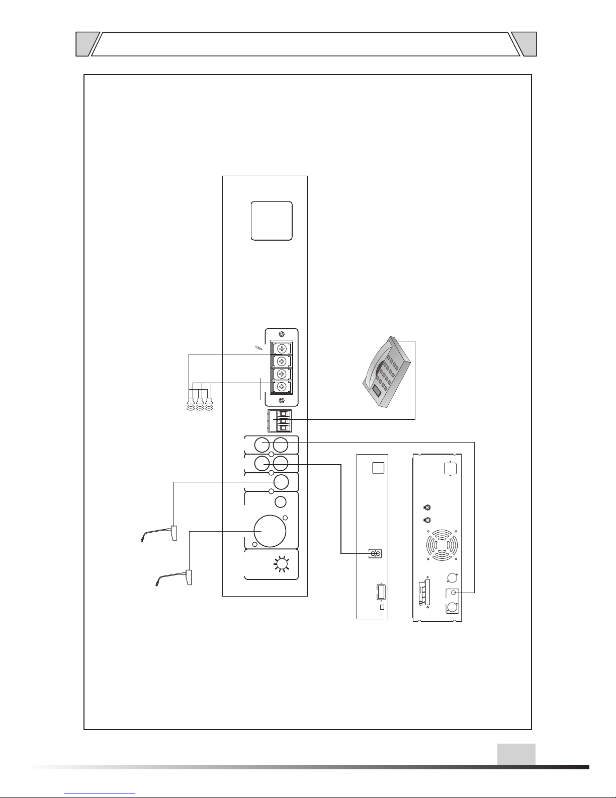
10
6. APPLICATIONS
COM 4-16Ω 70 V 100V
OUT PUT
TEL INPUT
G
-
+
LINE
OUT
AUX
MIC 2
MIC 1
INTERRU PT
TIME
A D J
MIC 1
XLR/6.3 0 INPUT
BAL / UNBAL
+48V
PHANTOM
SPEAKERS
TEL INPUT
MIC2
MIC1
AUDIO
OUT
R
L
COM
ADRESS TAG
AUDIO SOURCES
LINK
INPUTS
XLR BAL
1-GND
2-HOT+
3-COLD
1
2
3
1
2
3
OUTPUTS
INPUTS
POWER AMPLIFIER
Page 11
11
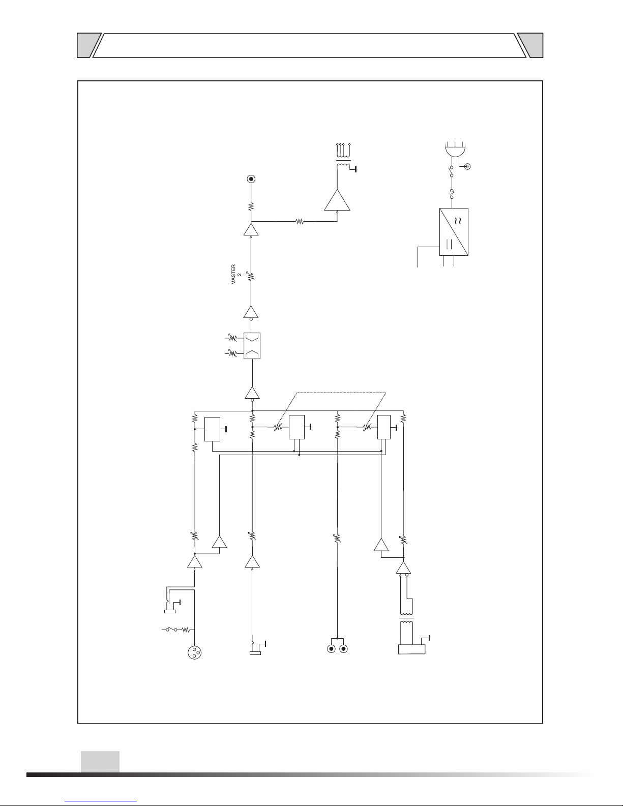
7. BLOCK DIAGRAM
COM P
COM P
V. C .A
V. C .A
LO W H IG H
LE V ER
R
L
LE V ER
LE V ER
MI C 1 IN T ER R UP T T IM E A DJ
+4 8 V
PH A NT O M
XL R
MIC 1
MIC 1 ( F ro n t p an e l )
MIC 2
TEL
AUX
MI X O U TP U T
COM
4-1 6Ω
70V
100 V
+4 5 V
+1 2 V
GN D
PO W E R SU P P LY
AC F U S E
PO W E R
SW I T H
AC P O W ER
V. C .A
GAIN /AMP
GAIN /AMP
GAIN /AMP
POWE R
AMP
GAIN /AMP
Page 12
8. SPECIFICATIONS
12
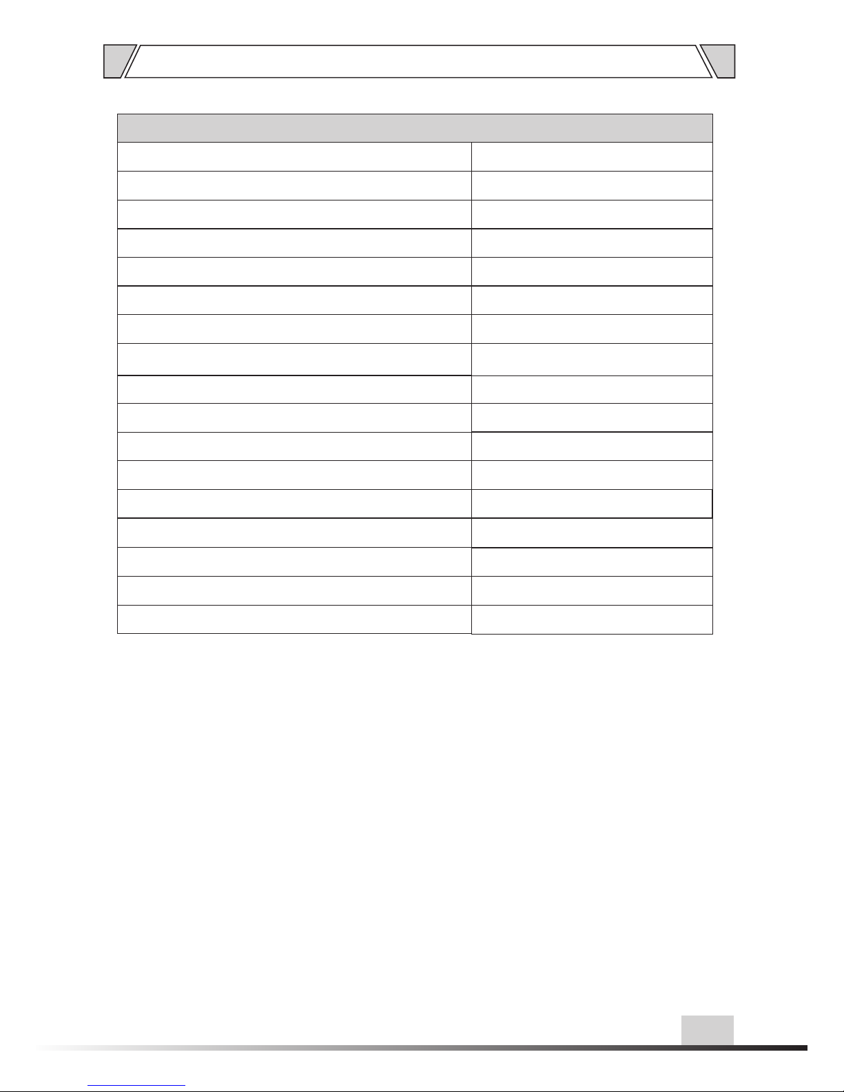
MIXER AM PLIFIER WITH C D
Model
Speak er Line Input
Ampli fier Section (amp In @ 1khz,8 ohm Load Outpu t)
Rated m aximum outpu t power (THD 1%)
Input s ensitivity /im pedance
Frequ ency respons e(At 1KHz Half p ower output)
MIC1~ 2 input sectio n( MI C in@1Khz , pre amp out)
Input s ensitivity /im pedance
AUX inp ut section(A UX in@1Khz, pr eamp out)
Input s ensitivity /im pedance
T-40AP
4~16Ω,7 0V,100 V
40W
1V/20 Kohms
80Hz~ 16KHz(+1dB /-3 )dB
5mV/5 00ohms,unb alance
2. 5 m V/500o h m s,bala n c e
300mV /500ohms
TEL input sect ion(AUX in@1 Khz, preamp ou t)
Input s ensitivity /im pedance
1V/50 0ohms
Power s ource
Power c onsumption
Net wei ght
Gross w eight
Dimen sions
~220V- 240V 50/60Hz
60W
4.0Kg
4.5Kg
320 x27 3x66mm
Page 13
13
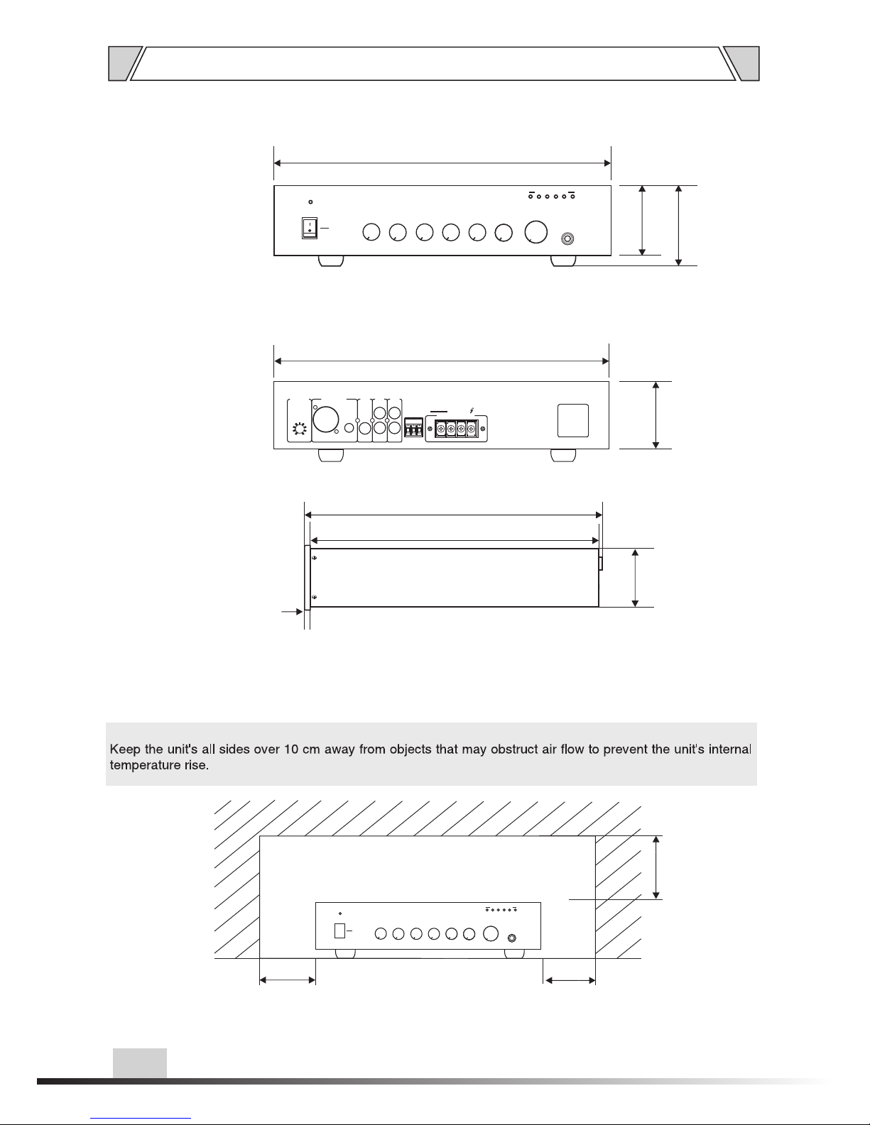
100
Over
100
Over
Over
100
UNIT :m m
9. DIMENSIONAL DIAGRAM
UNIT :m m
6
64
64
320
273
66
74
320
320
ON
OFF
BASS
-5
0
-1
-2
-3
-4
+1
+2
+3
+4
+5
TREBLE
-5
0
-1
-2
-3
-4
+1
+2
+3
+4
+5
0
1
2
3
4
5
6
7
8
9
10
MIC2
TEL
0
1
2
3
4
5
6
7
8
9
10
POWER
0
1
2
3
4
5
6
7
8
9
10
MIC1
AUX
0
1
2
3
4
5
6
7
8
9
10
5
0
1
2
3
4
6
7
8
9
10
MASTER
MIC1
INPUT
OUTPUT LEVEL
246 8 10
PROT
COM 4-16Ω 70V 100V
OUTPUT
TEL INPUT
G
-
+
LINE
OUT
AUX
MIC 2
MIC 1
INTERRUPT
TIME
A D J
MIC 1
XLR/6.30 INPUT
BAL / UNBAL
+48V
PHANTOM
ON
OFF
BASS
-5
0
-1
-2
-3
-4
+1
+2
+3
+4
+5
TREBLE
-5
0
-1
-2
-3
-4
+1
+2
+3
+4
+5
0
1
2
3
4
5
6
7
8
9
10
MIC2
TEL
0
1
2
3
4
5
6
7
8
9
10
POWER
0
1
2
3
4
5
6
7
8
9
10
MIC1
AUX
0
1
2
3
4
5
6
7
8
9
10
5
0
1
2
3
4
6
7
8
9
10
MASTER
MIC1
INPUT
OUTPUT LEVEL
246 8 10
PROT
Page 14

Vers io nV 0. 1
PUBLIC ADDRESS SYSTEM
 Loading...