

Page 1

PROFESSIONAL STEREO KARAOKE AMPLIFIER
T-2240K
OPERATION MANUAL
Please follow the instructions in this manual to obtain the optimum results from this unit.
We also recommend that you keep this manual handy for future reference.
PUBLIC ADDRESS SYSTEM
T-2120K
T-2080K
Page 2

TABLE OF CONTENTS
1. SAFETY PRECAUTIONS ...................................................................................... 3
2. PRODUCT DESCRIPTION ................................................................................... 5
3. FEATURES .............................................................................................................. 5
4. NOMENCLATURE AND FUNCTIONS
4.1 Front Panel ............................................................................................................ 6
4.2 Rear Panel............................................................................................................. 7
5. USER MANUAL....................................................................................................... 8
6. APPLICATIONS ......................................................................................................11
7. BLOCK DIAGRAM..................................................................................................12
8. SPECIFICATIONS .................................................................................................13
9. DIMENSIONAL DIAGRAM ...................................................................................14
2
Page 3

Be sure to read the instructions in this section carefully before use.
Make sure to observe the instructions in this manual as the conventions of safety symbols and messages
regarded as very important precautions are included.
We also recommend you keep this instruction manual handy for future reference.
Safety Symbol and Message Conventions
Safety symbols and messages described below are used in this manual to prevent bodily injury and property
damage which could result from mishandling. Before operating your product, read this manual first and
understand the safety symbols and messages so you are thoroughly aware of the potential safety
Indicates a potentially hazardous situation which, if mishandled, could
result in death or serious personal injury.
Indicates a potentially hazardous situation which, if mishandled, could
result in moderate or minor personal injury, and/or property damage.
When Installing the Unit
Do not expose the unit to rain or an environment
where it may be splashed by water or other liquids,
as doing so may result in fire or electric shock.
Use the unit only with the voltage specified on the
unit. Using a voltage higher than that which is
specified may result in fire or electric shock.
Do not cut, kink, otherwise damage nor modify the
power supply cord. In addition, avoid using the
power cord in close proximity to heaters, and never
place heavy objects -- including the unit itself -- on
the power cord, as doing so may result in fire or
electric shock.
Be sure to replace the unit's terminal cover after
connection completion. Because high voltage is
applied to the speaker terminals, never touch these
terminals to avoid electric shock.
Be sure to ground to the safety ground (earth)
terminal to avoid electric shock. Never ground to a
gas pipe as a catastrophic disaster may result.
Avoid installing or mounting the unit in unstable
locations, such as on a rickety table or a slanted
surface. Doing so may result in the unit falling
down, causing personal injury and/or property
damage.
Do not place cups, bowls, or other containers of
liquid or metallic objects on top of the unit. If they
accidentally spill into the unit, this may cause a fire
or electric shock.
Do not insert nor drop metallic objects or
flammable materials in the ventilation slots of the
unit's cover, as this may result in fire or electric
shock.
When the Unit is in Use
Should the following irregularity be found during
use, immediately switch off the power, disconnect
the power supply plug from the AC outlet and
contact your nearest ITC dealer. Make no further
attempt to operate the unit in this condition as this
may cause fire or electric shock.
If you detect smoke or a strange smell coming
from the unit.
If water or any metallic object gets into the unit
If the unit falls, or the unit case breaks
If the power supply cord is damaged (exposure of
the core, disconnection, etc.)
If it is malfunctioning (no tone sounds.)
To prevent a fire or electric shock, never open nor
remove the unit case as there are high voltage
components inside the unit. Refer all servicing to
your nearest ITC dealer.
3
Page 4

An all-pole mains switch with a contact separation of at least 3 mm in each pole shall be incorporated in
the electrical installation of the building.
When Installing the Unit
Never plug in nor remove the power supply plug
with wet hands, as doing so may cause electric
shock.
When unplugging the power supply cord, be sure
to grasp the power supply plug; never pull on the
cord itself. Operating the unit with a damaged
power supply cord may cause a fire or electric
shock.
When moving the unit, be sure to remove its power
supply cord from the wall outlet. Moving the unit
with the power cord connected to the outlet may
cause damage to the power cord, resulting in fire or
electric shock. When removing the power cord, be
sure to hold its plug to pull.
Do not block the ventilation slots in the unit's cover.
Doing so may cause heat to build up inside the unit
and result in fire.
Avoid installing the unit in humid or dusty locations,
in locations exposed to the direct sunlight, near the
heaters, or in locations generating sooty smoke or
steam as doing otherwise may result in fire or
electric shock.
If dust accumulates on the power supply plug or in
the wall AC outlet, a fire may result. Clean it
periodically. In addition, insert the plug in the wall
outlet securely.
Switch off the power, and unplug the power supply
plug from the AC outlet for safety purposes when
cleaning or leaving the unit unused for 10 days or
more. Doing otherwise may cause a fire or electric
shock.
When the Unit is in Use
Do not place heavy objects on the unit as this may
cause it to fall or break which may result in
personal injury and/or property damage. In
addition, the object itself may fall off and cause
injury and/or damage.
Make sure that the volume control is set to
minimum position before power is switched on.
Loud noise produced at high volume when power is
switched on can impair hearing.
Do not operate the unit for an extended period of
time with the sound distorting. This is an indication
of a malfunction, which in turn can cause heat to
generate and result in a fire.
Contact your ITC dealer as to the cleaning. If
dust is allowed to accumulate in the unit over a
long period of time, a fire or damage to the unit
may result.
4
Page 5

5
3. FEATURES
2. PRODUCT DESCRIPTION
1. Power output 2x80W, 2x120W, 2x240W.
2. Built-in multi-function effector to ensure more realistic result.
3. Independent three channel mic input, independent tone and volume control, accurately and
conveniently to control the mic signal.
4. Four stereo signal input, signal input with convenient automatic / manual selection
5. EMC input with highest priority, with priority switch. When turn off the switch priority, the other signal
can be input at the same time. Signal Input Priority: EMC MIC VCD, DVD, BGM.
6. Independent Tone and volume control. Overall tone and volume control
7. Audio signal with channel switch, freedom output signal: L+L, R+R, L+R.
8. Dual 8-segment LED output level indicator.
9. Microphone input with phantom power switch, to suit different microphone input
10.Temperature and short circuit protection
T-2080K-2120K-2240K are two-channel multimedia amplifier, output power is 2x80W, 2x120W and
2x240W, better for the large scale system, the model is with separate volume control, connect with 4 to
8 ohm speaker , it design with the impeccable protection include short circuit protection, DC output
protection, temperature protection, overload protection, also with best fan. The design not only ensure
efficient cooling, but also ensure a quiet working condition.
Page 6

4.1 FRONT PANEL
16. Left /right channel balance adjustment potentiometer
17. Master volume potentiometer
18. Power switch
19. Power indicator
21. Left /right channel temperature indicator
22. Left /right channel output level indicator
23. Priority indicator
24. Audio input selection button with indicator
25. Manual / automatic input mode indicator
26. Automatic level control indicator
27. Automatic level control switch
28. MIC1 mute potentiometer
29. MIC1~3 / MUSIC MID audio potentiometer
1. MIC1 ~ 3 / MUSIC bass potentiometer
2. MIC1 ~ 3 / MUSIC channel volume potentiometer
3. MIC1 ~ 3 / MUSIC treble potentiometer
4. MIC1 priority selection switch
5. Left/Right channel input indicator
6. Left/Right channel Input Selection Button
7. Reverberation Delay potentiometer
8. ECHO Relay potentiometer
9. Reverberation time adjustment potentiometer
11. Reverberation effects potentiometer
12. ECHO Repeat effects potentiometer
13. ECHO effector volume potentiometer
14. Master volume bass adjustment potentiometer
15. Master volume treble adjustment potentiometer
4. NOMENCLATURE AND FUNCTIONS
6
1 234
5 678 910
11121314
15 16
17
18 19
20
2122
23
24
2526
27
2829
Page 7
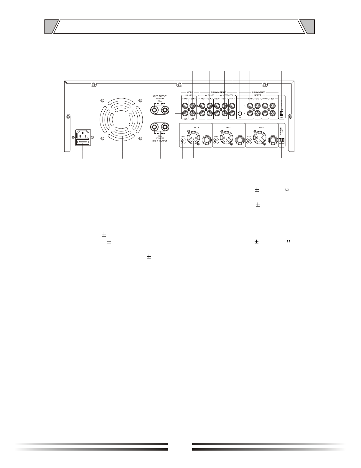
4.2 REAR PANEL
NOMENCLATURE AND FUNCTIONS
38. Audio input jack (DVD/VCD/BGM),
Input Sensitivity: 350mv 30mv/10k
39. EMC alarm voice input,
Input Sensitivity: 775mV 50mV
40. EMC mute switch is pressed, set EMC priority,
mute MIC1~3, MUSIC (DCD,VCD,BGM) channel
signal
41. Audio effects signal input,
input sensitivity: 350mV 50mV/10K
42. Audio signal effector output
43. Audio output, REC: recording output, connect to
external recording device. SW: subwoofer output
connect to external amplifier, PRE: pre-audio
output, connect to external amplifier)
44. Video signal input (DVD/VCD/BGM)
45. The video signal output (DVD/VCD/BGM), select
one mode as output
30. AC power input socket (with fuse box)
31. Vent and fan
32. Left/right channel output
(connected with impedance speaker)
33. MIC1~3 input gain potentiometer
(adjustment range: -46dB~-9dB)
34. MIC1~3 XLR input, (input sensitivity:
5mV (GAIN set +) 0.5 mV
350mV (GAIN set -) 30mV)
35. MIC1~36.3 stereo input interface
(input sensitivity: 5mV (GAIN set +) 0.5 mV,
350mV (GAIN set -) 30mV)
36. MIC1~3 phantom power switch
(output voltage DC + 48V)
37. Automatic audio selector switch
(when ON : automatic control mode working,
when OFF: manual control mode working, 24
buttons control on the front panel )
7
30
31
32 33
34
35
36
3738
39
40
41
42
4344
45
Page 8

5.1 Power on and power off
Input AC220V 10%, switch is turn on, blue power indicator light up , then the power is turned on. After
3 to 5 seconds, the amplifier is working normally. When switch is turn off, blue power indicator go out ,
then the power is turned off, all the indicators go out at the same time.
5.2 Mute function
MIC1 input audio signal (2~350mV):
Press "PRIORITY" button on the front panel , "PRIORITY MIC" indicator light up, "MUTE" potentiometer
set maximum, MIC1 potentiometer set to scale "4" or higher, priority function is working. MIC1 output
normally, the other channel signal is muting , mute result is controlled by audio signal input on MIC1,
MIC1 volume potentiometer and "MUTE potentiometer". Press "PRIORITY" button; MIC priority function
is turned OFF, MIC1 output mixed with other channel.
Note: When on EMC priority, MIC1 signal is muted.
5.3 Function of music signal automatic input selection and audio/video input selection
5.3.1 The real panel input selector switch "AUTOSEL" in the 0N position, "INPUT SELECTOR AUTO"
indicator lights, this moment is the automatic audio input selection state, between "BGM, VCD, DVD"
channel, switching time is about 3 to 5 seconds, choose the audio input channels, and the front panel
of the corresponding channel indicator will be synchronized lighted(eg DVD), while the video signal
input in "VIDEO INPUT DVD" port will also be output in "VIDEO OUT" port synchronously, and next
to the main amplifier output. When there is no input audio source, the default BGM channel.
5.3.2 The rear panel input selector switch "AUTOSEL" in the OFF position, "INPUT SELECTOR MANUAL
indicator lights, then manually select the input audio source; press any button of "BGM, VCD, DVD"
below the panel audio input selection " AU-DIOSELECTOR ", indicator lights, means select the input
channel which indicator shows. under the current state, the output signal source from pre-amp and
power amp is the channel output signal which indicator shows; and the current video output port is also
synchronized to match the output (for example: when the DVD audio and video signal input channel,
press "DVD" button representative DVD channel, then lights up "VIDEL INPUT DVD" lights, and turn
DVD audio signal path to the pre-amp output port, while the video signal input in "VIDEO INPUT DVD"
port will Synchronous output in "VIDEO OUT" port, and power amp output. )
Note: When the machine is in automatic audio input selection status, manual operation is disabled.
5.4 MUSIC signal channel switching function
press LRSEL key on the panel, L+R indicator lights, input L, R stereo signal, the power amplifier
output stereo signal, input MONO signal, the power amplifier output MONO signal;
press LRSEL key on the panel, L+L indicator lights, input mono L signal, the power amplifier output
is two L signal;
press LRSEL key on the panel, R+R indicator lights, input mono R signal, the power amplifier output
is two R signal.
Note: This function setting is only available for the music (DVD, VCD, BGM) input channel, MIC1~3
input channel settings are invalid.
5. USER MANUAL
8
Page 9

5.5 MIC volume adjustment
"MUSIC" is music potentiometer, control the input level of the music channel;
"MIC1~3" is volume potentiometer, control the input level of the microphone;
"BASS" is the bass potentiometer, adjust low frequency 65Hz~550Hz;
"MID" is the midrange potentiometer, adjust middle frequency 1KHz~3KHz;
"TREBLE" is the treble potentiometer, adjust high frequency 5KHz~10KHz.
5.6 MIC phantom power voltage switch
Open the corresponding code (1-3) of the phantom power switch(PHANTOM) between the corresponding
MIC1~3 input XLR 1-2 feet and 1-3 feet will have DC 45~48V voltage output. Turn off phantom power
switch(PHANTOM), off phantom voltage slowly drop to 0V.
5.7 MIC ALC (automatic level control)
Input Rated signal to the MIC channel, when the output is rated power; press "MIC ALC" key once, OFF
indicator lights, MIC ALC function off; press "MIC ALC" key again, the indicator -9, -12 , -14, -18 were lit
from left to right, ALC function on, while the output of the audio signal will decay -9dB,-12dB,-14dB,-18dB,
lastly cycle this function. (When power is off, the last set default)
5.8 Microphone effector
"DELAY" reverb delay effect potentiometer, adjustable time range: 0ms~100ms;
"DELAY" echo delay reverb effect potentiometer, adjustable time range: 80ms~240ms, adjustment of the
delay time should be based on the rhythm of the music and polish processing requirements, singing
method, actors and other voice characteristics to select the appropriate delay. In general: When meeting
voice and dialogue voice, usually adjusted "80ms ~ 110ms ", a short delay effect at this time, is more
suitable for short rhythm and single tone of voice, while singing, the adjustable delay time is often above
"150 ms", the sound is more charming at this moment.
"TIM" reverberation time adjustment potentiometer, adjustable time range: 0.1ms~2ms;
"REPEAT" repeat echo reverb effects potentiometer, adjustable times range: 1 to 12 times;
"REVERB" reverb potentiometer, adjust the microphone reverb (echo) effect of depth, and usually used
for drama, movies, TV shows simulated echo valley, Hall and Hall echo effect.
"ECHO" reverb echo effect potentiometer, adjust the reverb depth of microphone, the sound effect is more
abundant, but can not be stressed too deep, otherwise the sound will become dim and not clear, easy to
cause noise and howling.
"EFFVOL" microphone effect adjustment potentiometer, adjust the mixing ratio of reverberant Sound and
direct sound, generally reverberant sound level should be less than the direct sound level, adjustment of
the mixing ratio relates to the following factors:
Room reverberation characteristics. room reverberation is heavy, the mixing ratio should be smaller;
room reverberation is light, the mixing ratio can be increased appropriately.
Adapterization mode. Microphone away from the sound source, the mixing ratio should be smaller;
mic near to the sound source, the mixing ratio can be increase appropriately.
Timbre of sound source. sound source is plump and vigorous, clarity is poor, the mixing ratio should be
smaller; sound source is dry, thin and high-definition, the mixing ratio can be increased appropriately.
USER MANUAL
9
Page 10

5.9 master volume control
"Master Volume" potentiometer, control the master volume of power amp total level.
The master volume is recommended not to open the greatest potential to retain 20% of the spare values.
"BASS" potentiometer, adjust the low frequency 65Hz~550Hz of power amp.
"TREBLE" Treble potentiometer, adjust the high frequency 5KHz~10KHz of power amp.
"BALANCED" is adjusting the balance of the main amplifier. When "BALANCED" set in middle, L&R
channel has an output; when "BALANCED" set in R, R channel has an output, shut down the L-channel
output; when "BALANCED" set in L, L channel has an output, shut down the R-channel output.
5.10 output level indicator
Green signal indicator, the lights (from left to right, from 1 to 8 green LED) indicates that the channel's
output level, brightness will change with the changable of output level amplitude size. Lights on the circuit
is connected in parallel at the output of the amplifier, so that when the panel master volume potentiometer
rotates to the minimum position, regardless of whether there is an input signal, lights will not illuminate.
Orange peak indicator lights, when this is highlighted, indicate the output signal of the amplifier channel
has reached the peak (rated power).
Red indicator light of peak clipping. The range of the amplifier output signal of the channel is more than
the summit when the light turns on, peak clipping is appeared . If it happens, please turn down the signal
output or diminish output gain.
Red indicator light of overheating protection, the channel of this amplifier is turn off to protect the
equipment as the overheating. In this case, the "Port" light is lit. please close the amplifier, check whether
it is in a good ventilation, if the wind can go smoothly through wind grid .If the load impedance is too small.
The red indicator light of protection, The machine in the protection state when this indicator turn on, It is
convenient to find out the problem. Indicator light is lit about 3 s ~ 5 s continuously when startup amplifier
self-check process. During this period the amplifier is no output. This phenomenon is normal. Indicator
protection function: overheating protection, overload protection, short circuit protection. If not belong to
these after checking but with bright "PORT" light. There is something wrong with the amplifier, please
send the amplifier to a professionals to repair.
USER MANUAL
10
Page 11
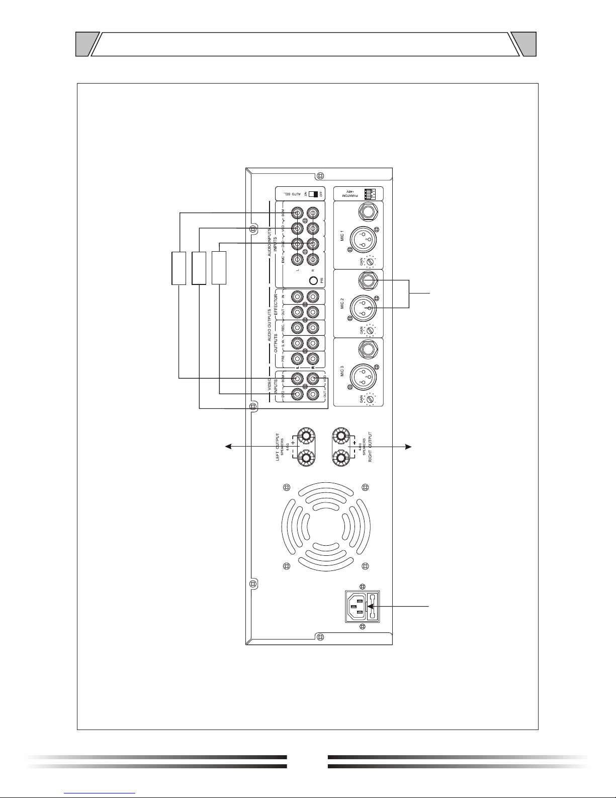
6. APPLICATIONS
11
BGM
VCD
DVD
Connect microphone
Power input
Connect main speakers
Connected main speakers
Page 12

7. BLOCK DIAGRAM
12
3
2
1
3
2
1
3
2
1
EFFECT
GND
GND
GND
3
2
1
GND
3
2
1
3
2
1
FBC
AMP
GND
EFFECTOR-OUT
EFFECTOR-IN
132
132
132
PRE-OUT
S.W-OUT
MIC1
MIC2
MIC3
MIC1
MIC2
MIC3
AC220V
(MCU/LA72730)+5V
AMP-POWER
VCC48V
PHANTOM+48V
POWER
BGM
VCD
DVD
MCU
VIDEO-OUT
LIN
BGM
VCD
DVD
A
B
2SD1302
2SD1302
2SD1302
BGM
VCD
DVD
RIN
TONE
TONE
TONE
REC-OUT
3
2
1
3
2
1
L H
RP
MUTE
LA72730
L
R TONE
L1H1
RP1
3
2
1
L1 H1
RP1
L1 H1
RP1
L1 H1
RP1
GND
GND
GND
GND
GND
MIC-MUTE
TONE&VOL
CD4052
STEREO
LCH MONO
RCH MONO
L
GND
GND
GND
GND
GND
GND
123 4
5
6
GND
GND
GND
GND
BGM
VCD
DVD
EMC
GND
GND
GND
GND
BGM
VCD
VIDEO-OUT
+12V
-12V
+7.5V
-7.5V
GND AMP-OUT
GND
GND
GND
PBC
LR-SEL
BGM/VCD/DVD
PHAN TOM-SW
IN-AUTO SEL
SEL
R
LIN
GND
GND
GND
GND
BGM
VCD
DVD
EMC
RIN
L H
RP
2SD1302
3
2
1
3
2
1
GND
GND
3
2
1
GND
3
2
1
3
2
1
AMP
GND
EFFECTOR-OUT
EFFECTOR-IN
PRE-OUT
S.W-OUT
REC-OUT
3
2
1
3
2
1
L1 H1
RP1
3
2
1
GND AMP-OUT
GND
GND
GND
L1H1
RP1
L1 H1
RP1
GND
GND
LCH
RCH
MUTE
BAL
VCD
DVD
VCD
DVD
3
2
1
3
2
1
GND
BGM
VCD
DVD
L+L L+R R+R
DVD
+3.3V
FBC
-3.3V
3
2
1
3
2
1
EMC-LIN
EMC-RIN
EMC-MUTE
R?
RES
GNDGND
R
L
EMC-R
EMC-L
EMC-R
EMC-L
Page 13
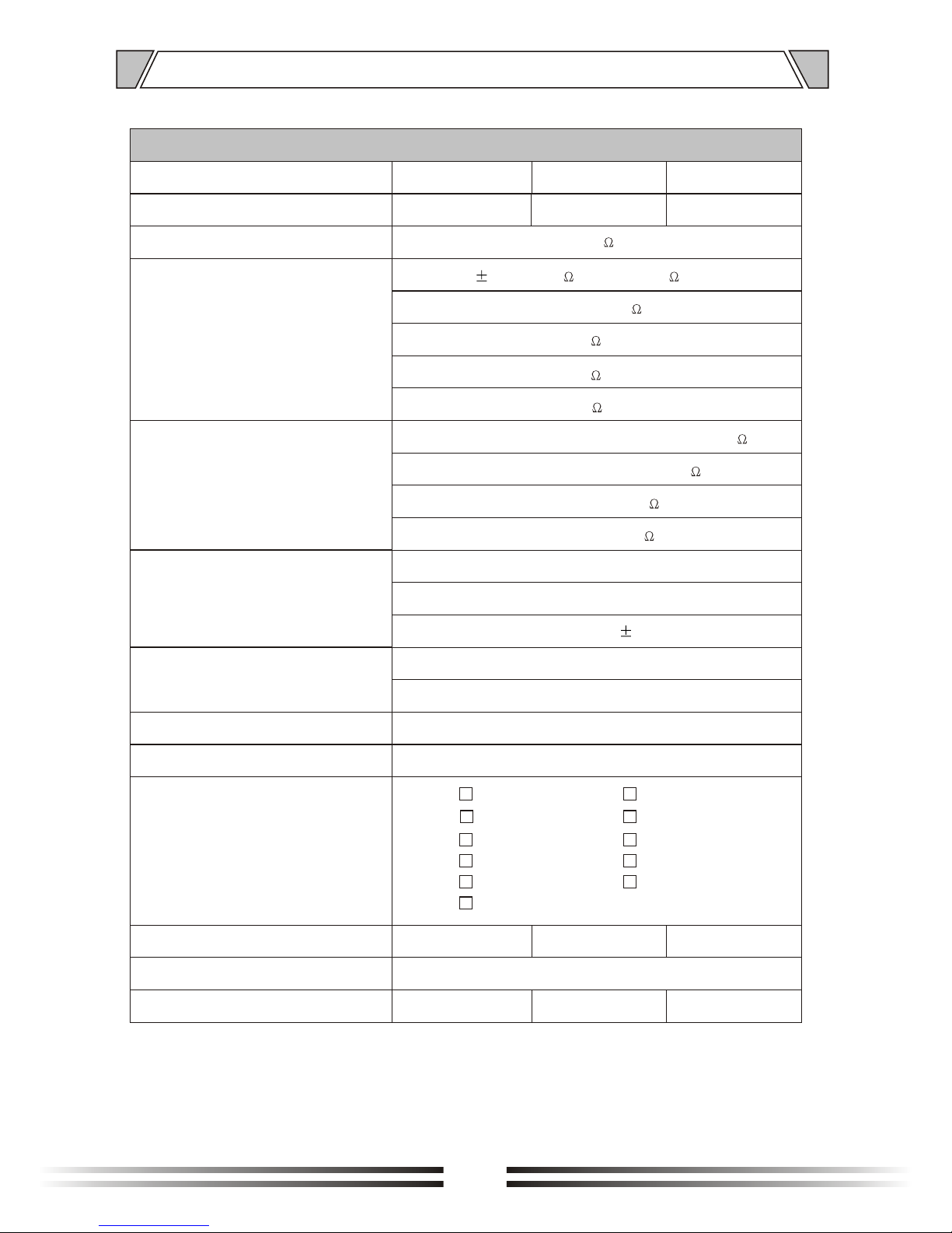
8. SPECIFICATIONS
13
Model
Output of rated power
Speaker output
The input sensitivity and impedance
T-2080K
2x80W
4~8
Mic1,2,3: 2.5mV/600 ~775mV/10K (balance input)
AUX(KARAOKE): 200mV/10K (unbalance input)
DVD: 300mV/10K (unbalance input)
VCD: 300mV/10K (unbalance input)
BMG: 300mV/10K (unbalance input)
Output
External processor input/output: 775mV/470
Heavy bass(150Hz): 1.5V/470
Pre: 1000mV/470
Video:1VP-P/75
Effector parameters
ECHO DELAY: 80ms~240ms; ECHO REPEAT: 1~12
REVERB DELAY: 0ms~100ms; REVERB REPEAT: 0.1S~2S
20Hz~20KHz( 3dB)
Signal to noise ratio
Mic 1,2,3: 66dB
Music: 80dB
Harmonic distortion
Less than 0.1% at 1KHz, 1/3 rated power
Indicator light
Power supply, outgoing level
Power input
Power consumption
280W
Dimension(mm)
Weight
430x399x132mm
11Kg
T-2120K
T-2240K
2x120W
2x240W
400W
11.46Kg
700W
13.52Kg
~110V 50Hz ~110V 60Hz
~120V 50Hz ~120V 60Hz
~220V 50Hz ~220V 60Hz
~230V 50Hz ~230V 60Hz
~240V 50Hz ~240V 60Hz
~220-240V 50-60Hz
Page 14
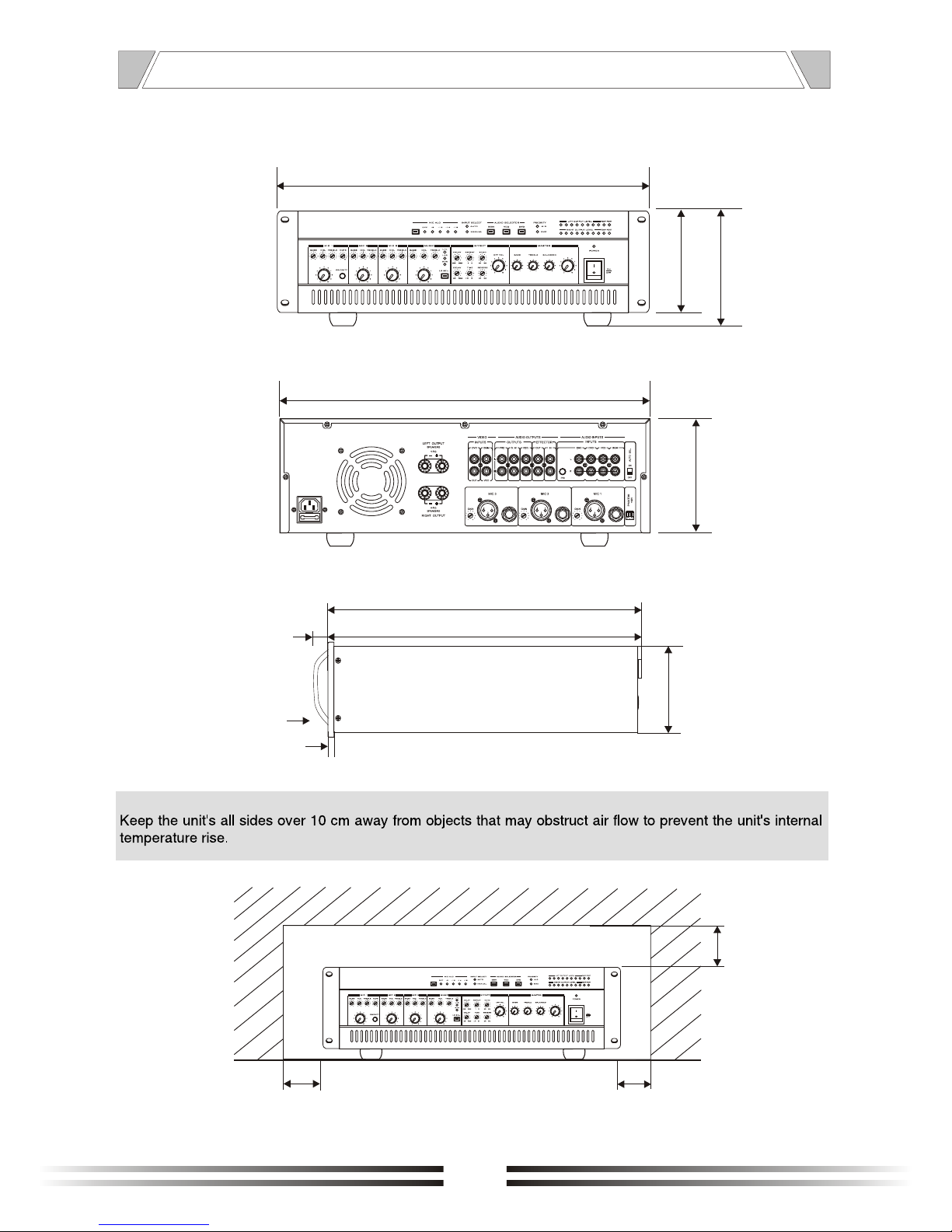
9. DIMENSIONAL DIAGRAM
10
Over
10
Over
Over
10
UNIT :mm
132
132
140
430
484
UNIT :mm
5
14
132
25
374
360
6
Page 15

PUBLIC ADDRESS SYSTEM
VersionV0.1
 Loading...