

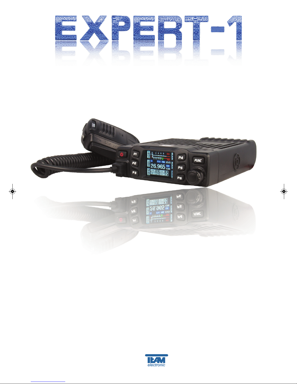
Mobil Funkgerät
mobile radio
CB ohne/no CTCSS/DCS Art.-Nr./item no. CB3215
CB mit/with CTCSS/DCS Art.-Nr./item no. CB3217
HAM ohne/no CTCSS/DCS Art.-Nr./item no. PR8124
HAM mit/with CTCSS/DCS Art.-Nr./item no. PR8125
Bedienungsanleitung
manual
CB
HAM

Expert-1 Mikrofon Montagebügel
Kabel
Unterlegscheiben
Justierschrauben
Wir gratulieren Ihnen zum Kauf des TEAM Expert-1. Sie haben ein hochwertiges, solides Mobilfunkgerät erworben, das den professionellen Ansprüchen der Funkkommunikation gerecht wird.
Die Leistungsfähigkeit und die Qualität des Expert-1, welches die neuesten
Technologien beinhaltet, werden Sie zufrieden stellen.
Um die volle Funktionalität Ihres neuen Gerätes kennenzulernen und um
eine sachgemäße Behandlung und Bedienung zu garantieren, bitten wir
Sie diese Bedienungsanleitung zu lesen.
Das Expert-1 gibt es in den Varianten CB (anmelde- und gebührenfrei) und HAM, jeweils
in unterschiedlichen Versionen mit bzw. ohne CTCSS/DCS. Bitte beachten Sie, dass Sie
für den Betrieb der Amateurfunkvariante Expert-1 HAM eine gültige Amateurfunklizenz
benötigen.
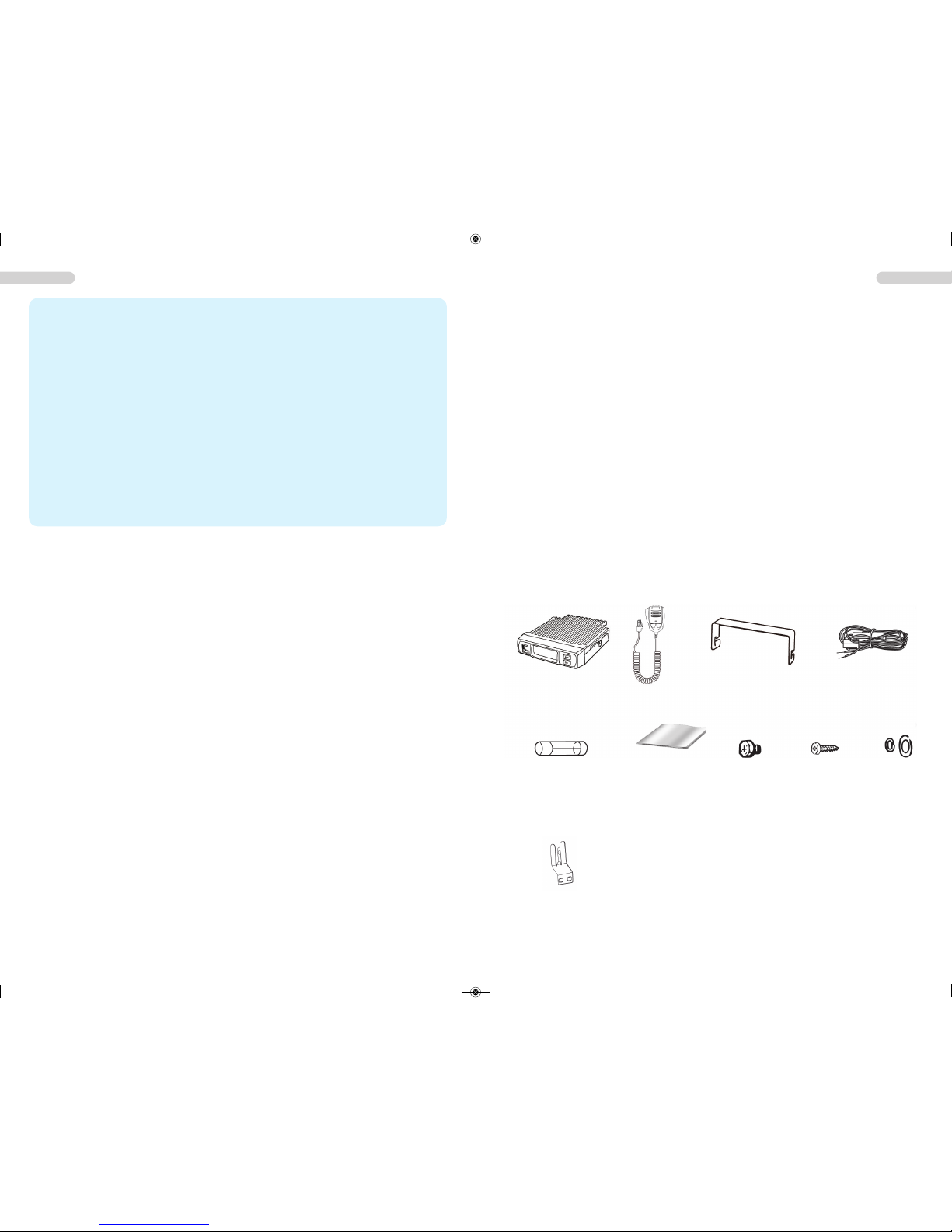
LIEFERUMFANG
Bitte entnehmen Sie das Gerät vorsichtig aus der Verpackung. Untersuchen Sie den Inhalt auf
Vollständigkeit. Sollten eines der Teile der folgenden Liste fehlen oder defekt sein, so kontaktieren Sie Ihren Fachhändler unverzüglich.
Bedienungsanleitung
Sicherung
5A / 250V
2 3
Treibschrauben
Mikrofonhalter
Deutsch Deutsch
VORSICHTMASSNAHMEN
Bitte beachten Sie die folgenden Vorsichtsmaßnahmen um Verletzungen, Feuer oder Schäden
am Gerät zu vermeiden.
Zu langes Senden oder übermäßig langer Gebrauch mit hoher Sendeleistung führt zu Erhitzung
am hinteren Teil des Funkgerätes.
Achten Sie darauf, dass Sie das Gerät nie für längere Zeit direktem Sonnenlicht oder anderen
Hitzequellen aussetzen.
Vermeiden Sie staubige oder feuchten Plätze für das Expert-1.
Sollten Sie eine außergewöhnlichen Geruch oder Rauch feststellen, schalten Sie das Gerät
sofort aus und kontaktieren Ihren Fachhändler.
Modifizieren Sie das Gerät unter keinen Umständen.
Lassen Sie Service- und Reparaturarbeiten nur von einem qualifizierten Fachhändler ausführen.
HINWEIS : Bevor Sie dieses Gerät benutzen, lesen Sie bitte diese Bedienungsanleitung.
INHALTSANGABE
VORSICHTSMASSNAHMEN 3
LIEFERUMFANG 3
BEDIENELEMENTE 4
Frontblende, Rückseite, Mikrofon
MONTAGE 5 - 7
Bügelhalterung, Mikrofonhalterung,
Antenne, Antennenanschluss,
Anschluss an das Stromnetz,
Sicherungen, Anschluss externer
Lautsprecher, Anschluss Mikrofon
ÜBERSICHT FUNKTIONEN 8
BETRIEB 8 - 9
Ein/Aus, Lautstärke, Stummschaltung,
Kanalwahl, Senden, Empfang,
Rauschsperre, Tastatursperre
MULTIFUNKTIONSTASTEN 10 - 13
MENÜS 13 - 15
TECHNISCHE DATEN 29
CB FREQUENZEN 30
CTCSS / DCS 31
Expert1_man_2:Layout 1 8/26/2016 11:03 AM Page 2

MONTAGE
Wählen Sie den Standort des Expert-1 in Ihrem Fahrzeug nach den Kriterien der besten und einfachsten Bedienbarkeit. Das montierte Gerät darf unter keinen Umständen den Fahrer in seiner
Bewegungsfreiheit in irgendeiner Weise behindern oder einschränken.
Achten Sie bei der Standortauswahl auf gute Luftzirkulation und keine direkte Sonnenbestrahlung.
Bügelhalterung
1. Verwenden Sie für die Montage des Haltebügels die beiden Treibschrauben und die Unterlegscheiben.
2. Für die seitliche Befestigung des Expert-1 am Bügelhalter sind die Feststellschrauben mit
den Unterlegscheiben vorgesehen. Drehen Sie das Gerät in einen passenden Winkel
bevor Sie die Schrauben festdrehen.
4 5
Rückseite
Mikrofon
1 : POW - Ein-/Ausschalter
2-7: P1-6, programmierbare
Funktionstasten
8 : FUNC - Menütaste und PF1-6
Umschaltung
11 : SP - Anschlussbuchse für externen Lautsprecher, 3,5 mm
12 : Stromversorgungskabel mit Sicherung
13 : ANT - PL-Antennenbuchse
9 : Mikrofonanschluss RJ-45
10 : Kanalwahl-Drehschalter und
Menüsteuerung, Bestätigungstaste
Mikrofonhalterung
Wählen Sie den Standort des Mikrofons in Ihrem Fahrzeug nach den Kriterien der besten
und einfachsten Bedienbarkeit. Das Mikrofon darf unter keinen Umständen den Fahrer in
seiner Bewegungsfreiheit in irgendeiner Weise behindern oder einschränken.
Montieren Sie den Mikrofonhalter mit den im Lieferumfang enthaltenen zwei Schrauben
an die gewünschte Stelle im Fahrzeug.
Antenne
Die Antenne gehört zu den wichtigsten Teilen einer Funkanlage. Die Wahl der Antenne und
des Montageortes ist von großer Bedeutung für die maximale Reichweite Ihrer Funkanlage. Die folgenden Kriterien sollten Sie bei der Wahl des Antennenstandortes und der
Montage berücksichtigen.
Allgemein gilt :
> Die Antenne muss für den Funkbetrieb im entsprechenden Frequenzbereich geeignet sein.
> Der Standort der Antenne sollte möglichst hoch und unverbaut sein.
> Das Antennenkabel muss unbeschädigt, und die Stecker ordnungsgemäß angeschlossen sein.
> Das Antennenkabel sollte nicht zu stark geknickt werden.
> Antennen mit einer größeren mechanischen Länge erzielen bessere Reichweiten.
Bei der Montage von Mobilantennen ist folgendes zu beachten:
> Die Antenne sollte in der Mitte eines größeren Karosserieteils montiert werden.
> Der Antennenfuß sollte möglichst Kontakt zu einer leitenden Metallfläche des Karosserie-
bleches haben.
Außer der Festmontage, bei der ein Loch in die Karosserie Ihres Fahrzeuges gebohrt werden muss, gibt es noch weitere Möglichkeiten der Befestigung, z.B. Magnetfuß, Spiegelhalter oder mit der Verwendung einer Glasklebeantenne.
> Um Störungen bei Radio- und Fernsehempfang zu vermeiden, sollte die Funkantenne
nicht in unmittelbarer Nähe der Radio- und Fernsehantenne montiert werden.
Achten Sie auf die korrekte Installation der Funkanlage.
WARNUNG:
▲ Verwenden Sie nur eine passende Antenne, welche den Anforderungen des Expert-1
entspricht. Bei Fragen kontaktieren Sie bitte Ihren Händler.
▲ Achten Sie auf die korrekte Erdung der Antenne.
▲ Vor dem ersten Betrieb muss die Antenne angeschlossen werden um mögliche Schäden
an der Endstufe des Expert-1 zu vermeiden.
Deutsch Deutsch
13
11
12
Expert1_man_2:Layout 1 8/26/2016 11:03 AM Page 4

6 7
Anschluss externer Lautsprecher
Wenn Sie einen externen Lautsprecher anschließen, verwenden Sie bitte einen 8 Ohm Lautsprecher mit 3,5 mm Anschlussstecker.
1. Installieren Sie den Lautsprecher in einer günstigen Position. Beachten Sie die Kabel-
länge zum Gerät.
2. Schließen Sie den Lautsprecher an die Lautsprecherbuchse (11) an.
Mikrofon Anschluss
Stecken Sie den RJ-45 Anschlussstecker des Mikrofons mit der Tastnase nach unten zeigend
komplett in die Anschlussbuchse (9) ein. Beim korrektem Einrasten des Steckers ertönt ein
leises Klicken.
Der Modularstecker ist mit einer Gummiabdeckung zwecks Staubschutz versehen. Zum Abnehmen des Steckers drücken Sie den unteren Teil der Gummiabdeckung und ziehen gleichzeitig den Stecker ab.
Bitte beachten Sie, dass für das Senden und Empfangen von Signalen das Mikrofon angeschlossen sein muss.
Hinweis:
für die Software-Programmierung des Gerätes entfernen Sie das Mikrofon und schließen
das USB PC-Datenkabel an, welches im Lieferumfang der optionalen Software
T-UP36 enthalten ist.
Deutsch Deutsch
Antennenanschluss
Befestigen Sie den PL-Antennestecker in der Antennenbuchse (13), welche sich auf der
Rückseite des Gerätes befindet.
Ebenso ist auf eine ordentliche Verbindung des Antennenkabels mit dem Antennenfuß zu
achten. Nicht einwandfreie Verbindungen können zu einem Defekt des Gerätes führen und
die Funkreichweite erheblich verringern. Die Antennenanlage (nicht im Lieferumfang enthalten) sollte sehr gut an das Funkgerät angepasst sein, ansonsten wird ein Teil der Sendeleistung an der Antenne reflektiert und nicht abgestrahlt. Das führt ebenfalls zu einer geringeren
Reichweite der Funkanlage.
Anschluss an das Stromnetz
Hinweis:
Das Expert-1 verfügt über eine automatische 12/24 V Umschaltung. Demnach muss die Spannung muss 13,8 / 28 V DC, mit negativer Erdung betragen. Stellen Sie sicher, dass die positive
( +, rot ) und negative ( -, schwarz ) Polarität korrekt ist, bevor Sie das Gerät anschließen. Der
Stromanschluss an das KFZ-Bordnetz muss durch einen Fachmann erfolgen.
Schliessen Sie das Netzkabel direkt an die Autobatterie an. Verwenden Sie keinen Zigarettenanzünder-Adapter, da dieser Anschluss nicht über genügend Stromstärke für den Betrieb
des Gerätes verfügt. Achten Sie auf die korrekte Polarität der Kabel beim Anschließen an
die Batterie.
ACHTUNG
> Vor Anschluss des Stromversorgungskabels an die Batterie entfernen Sie bitte alle negat-
tiven Zuleitungen zur Batterie. Nach abgeschlossener Montage und Verkabelung überprüfen Sie bitte noch einmal den korrekten Anschluss, bevor Sie das negative Anschlusskabel
mit der Batterie verbinden.
> Wenn die Sicherung offen ist, überprüfen diese auf mögliche Schäden. Im Falle eines
Defekts, ersetzen Sie diese bitte.
Austausch Sicherung
Das Netzkabel welches das Gerät mit der Stromquelle verbindet verfügt über eine 5A/250V
Sicherung. Achten Sie darauf, dass sie die korrekte Sicherung verwenden. Schäden am
Gerät könnten sonst die Folge sein.
Sollte die Sicherung durchbrennen, finden Sie die Ursache und beheben Sie den Fehler. Danach tauschen Sie die Sicherung aus. Sollte die Sicherung wieder durchbrennen, unterbrechen Sie die Kabelverbindung und kontaktieren Sie Ihren Händler.
1. Drücken Sie den Verschluss des Sicherungsgehäuses nach unten und Drehen Sie den
Verschluss gegen den Uhrzeigersinn.
2. Tauschen Sie die defekte Sicherung aus und mon-
tieren Sie den Verschluss.
Expert1_man_2:Layout 1 8/26/2016 11:03 AM Page 6

ÜBERSICHT FUNKTIONEN
Für die Software-Programmierung des Expert-1 Mobilfunkgerätes ist die optionale Software
T-UP36 bestimmt. Abhängig von der Geräteversion ist die Software T-UP36 CB oder T-UP36
HAM zu verwenden.
Geräteeigenschaften und Funktionen in der Übersicht:
FTF LCD Anzeige
12/24 V Umschaltung, automatisch
Kühlkörper aus Metalllegierung
6 programmierbare 3-fach Funktionstasten
(38 CTCSS / 104 DCS - optional)
AM/FM Multi Norm
DTMF
PTT-ID (DTMF)
SQ/ASQ, Rauschsperre
RF Gain
Kanalsuchlauf
Zweikanalsuchlauf
Warnton
Roger Ton, 8-Tonfolgen - nur programmierbar mit Software
Vorrangskanal 9/19, andere Belegung programmierbar mit Software
Noise Blanker
HI-CUT
8 Speicherkanäle (nur HAM)
Sendezeitbegrenzung TOT
Sendesperre auf besetzten Kanälen
Hintergrundbeleuchtung, 3-stufig einstellbar
Automatische Einschaltung
Tastatursperre
Multifunktionstasten-Funktionen:
MOD (Betriebsart - AM/FM), RFG (Empfangssignal-Empfindlichkeit), EMG (Vorrangskanal 1/2),
VOL (Lautstärke), SQL (Rauschsperre), POW* (Sendeleistungsumstellung), DSP (Kanal-/Frequenzanzeige), SCA (Kanalsuchlauf), MEM* (Speicherkanäle), BND (Normenauswahl), DW
(Zweikanalüberwachung), CAL (DTMF-Ruf Senden), NB (Geräuschfilter), RB (Rogerton), HIC
(High Cut Frequenzfilter), CDT (CTCSS/DCS**), REP (Relaisbetrieb, +/- Frequenzablage*)
* nur HAM Version / ** optional
BETRIEB
Ein/Aus
Zum Einschalten des Gerätes genügt ein kurzes Drücken der Ein-/Aus-Taste POW (1). In der Anzeige erscheint kurzzeitig das TEAM Logo und bei aktiviertem Warnton (Beep Tone) ertönt ein
kurzer Ton, bevor die LCD Anzeige in den Betriebsmodus schaltet.
Zum Ausschalten halten Sie die Ein-/Aus-Taste POW (1) solange gedrückt bis das TEAM
Logo in der LCD Anzeige erscheint, bevor das Gerät auschschaltet.
Mit der Funktion AOP kann das Gerät für die automatische Einschaltung aktiviert werden.
Hierbei schaltet sich das Gerät, beim Betätigen der Zündung, automatisch ein.
Deutsch Deutsch
8 9
Lautstärke
Zum Einstellen der Lautstärke Drücken Sie die entsprechende Multifunktionstaste, welche
mit der Funktion VOL belegt ist. In der untersten Zeile der Anzeige erscheint das Symbol
VOL: X, wobei X dem aktuellen Wert entspricht. Wählen Sie den gewünschten Wert (1-56)
mit Hilfe der Kanalwahltasten am Mikrofon oder dem Kanalwahldrehschalter (6) am Gerät.
Bestätigen Sie Ihre Eingabe durch Drücken der Sendetaste oder des Kanalwahldrehschalters
oder warten Sie ca. 5 Sekunden bis der eingestellte Wert automatisch übernommen wird.
Stummschaltung
Zum Stummschalten des Lautsprechers drücken Sie im eingeschalteten Zustand des Gerätes kurz die Ein-/Aus-Taste (1). Im unteren Teil der Anzeige erscheint AUDIO:MT (MT = mute,
d.h. stumm) für einige Zeit.
Um die Stummschaltung zu deaktivieren, drücken Sie bitte erneut die Ein-/Aus-Taste. In der
Anzeige erscheint nun AUDIO:Esc (Esc = escape, d.h. verlassen).
Hinweis: das Signal wird nicht komplett stummgeschaltet, sondern nur extrem reduziert.
Kanalwahl
Für die Kanalwahl stehen die Kanalwahltasten UP/DN am Mikrofon und der Kanalwahldrehschalter (10) am Gerät zur Verfügung. Bei aktiviertem Bestätigungston ertönt beim Umschalten ein kurzer Ton.
Langes Drücken der Mikrofon-Kanalwahlasten aktiviert den Schnelllauf.
Senden
Zum Senden eines Sprachsignals halten Sie die Sendetaste am Mikrofon und sprechen im
ungefähren Abstand von 10 cm.
In der Anzeige erscheint das rote Sendesymbol T, das integrierte S-Meter zeigt in der oberen
Skala (P) die Signalstärke an. Unter der Frequenz- bzw. Kanalanzeige werden die Einstellungen PWR (Sendeleistung), RB (Rogerton), SPL (Frequenzablage - nur HAM) und TOT
(Sendezeitbegrenzung) werden angezeigt.
Empfang
Das empfangene Signal wird im Gerätelautsprecher wiedergegeben. Die Signalstärke wird
im integrierten S-Meter auf der unteren Skala (S) angezeigt.
Unter der Frequenz- bzw. Kanalanzeige sind die Einstellungen Lautstärke (VOL), Rauschsperre (SQL oder ASQ), Empfangssignalstärke (RFG) und Frequenzfilter (HIC) sichtbar.
Hinweis: bei der Verwendung der optionalen CTCSS-Funktion ist zu beachten, dass bei aktivierter CTCSS/DCS Kodierung, der Lautsprecher das Signal nur wiedergibt wenn es diesselbe CTCSS/DCS Kodierung verwendet.
Rauschsperre
Es können wahlweise die manuelle Rauschsperre SQL oder die automatische Rauschsperre
ASQ aktiviert werden. Abhängig von der Einstellung erscheint entweder das Symbol ASQ
oder SQL in der Anzeige. Für beide Arten besteht die Möglichkeit am Gerät den programmierten Wert zu verändern
SQL: Off (Aus), 1-28 / ASQ: 1-9.
Tastatursperre
Die Tastatursperre wird durch langes Drücken des Kanalwahldrehschalters (10) aktiviert. Alle
Tasten, mit Ausnahme der Sendetaste, werden blockiert, inkl. der Ein/Aus Taste (1). In der
Anzeige erscheint Key Lock in roten Buchstaben. Diese Anzeige erlischt nach ca. 5 Sekunden ohne Tastenaktivität und erscheint wieder beim Drücken einer beliebigen Taste.
Zum Deaktivieren der Tastatursperre den Kanalwahldrehschalter erneut drücken, bis in der
Anzeige Key Unlock in weißer Schrift erscheint.
Expert1_man_2:Layout 1 8/26/2016 11:03 AM Page 8

10 11
Deutsch Deutsch
PF3
EMG (Vorrangskanal 1/2)
Schaltet vom aktuellen Kanal auf den per Software programmierbaren Vorrangskanal 1,
bei erneutem Drücken der Taste auf den Vorrangskanal 2, und bei drittmaligem Drücken
wieder auf den Ursprungskanal. Bei aktiviertem Vorrangskanal leuchtet das Symbol EMG
rot in der Anzeige.
In der Vorbelegung ist Vorrangskanal 1 mit Kanal 9 und Vorrangskanal 2 mit Kanal 19 belegt.
Dies kann per Software-Programmierung geändert werden.
MEM (Speicherkanäle)
Diese Funktion ist nur in der Amateurfunkversion (HAM) verfügbar. In der CB-Variante erscheint das Symbol ERROR in roten Buchstaben in der Anzeige.
Per Software oder am Gerät können max. 8 Kanäle in diesem Speicher abgelegt werden.
Das Drücken der Taste aktiviert/deaktiviert die MEM Speicherbank. Im aktiven Zustand
erlischt die Anzeige des aktuellen Frequenzbandes und das Symbol MEM (im Kanalmodus) bzw. Mxx (im Frequenzmodus) zeigt den Speicherkanalmodus an. Der gewünschte
Speicherkanal wird mit den Mikrofon-Kanalwahltasten oder dem Kanalwahldrehknopf (10)
am Gerät gewählt.
Zum manuellen Speichern von MEM Speicherkanälen wählen Sie den gewünschten
Kanal. Halten Sie nun die MEM Taste bis in der Anzeige das Symbol CH-01 (die Speicherkanalnummer 01 leuchtet blau) erscheint. Wählen Sie nun den Speicherkanal auf
dem die Frequenz gespeichert werden soll und halten erneut die MEM Taste um die Auswahl zu speichern. Ist der gewählte MEM Speicherkanal noch nicht belegt, blinkt die
Speicherkanalnummernanzeige, ist der gewählte MEM Kanal belegt, leuchtet die MEM
Kanalnummer.
Hinweis: Die Modi MEM und EMG schließen sich gegenseitig aus, die Fehlermeldung
Error wird in diesem Fall angezeigt.
HIC (High Cut Frequenzfilter)
Aktivivert den Frequenzfilter für hohe Frequenzen. Diese Funktion hilft das Signal zu verbessern im Falle von Frequenzstörungen im hohen Frequenzbereich.
PF4
VOL (Lautstärke)
Aktiviert die Lautstärkeeinstellung. Den gewünschen Wert (1-56) stellen Sie mit den Kanalwahltasten am Mikrofon oder dem Kanalwahldrehschalter (10) am Gerät ein.
Zum Einstellen der optimalen Lautstärke, deaktivieren Sie kurzzeitig die Rauschsperre
SQL. Es ertönt das typische Frequenzrauschen auf dem Kanal.
BND (Normenauswahl)
Diese Funktion ist nur in der Amateurfunkversion (HAM) verfügbar. In der CB-Variante erscheint das Symbol ERROR in roten Buchstaben in der Anzeige.
Das Drücken der Funktionstaste schaltet zwischen den verschiedenen Frequenznormen
bzw. Kanalbänken um. In der Anzeige erscheint das entsprechende Symbol.
In der Amateurfunkvariante HAM stehen die Kanalbänke A-J, VFO und MEM zur Auswahl.
Für die Kanalbänke A-J können jeweils 40 Kanäle programmiert werden. Für die Speicherbank MEM stehen 8 Kanäle zur Verfügung. Bei der Auswahl VFO können alle Frequenzen
innerhalb des Frequenzbandes manuell mit Hilfe der Kanalwahlfunktion eingestellt werden.
Für die Normenumschaltung in der CB-Version, halten Sie bitte die Menütaste FUNC (8)
beim Einschalten des Gerätes gedrückt. In der Anzeige erscheint: CB FREQ - Select
Band: xx BAND (xx steht für das aktuelle Frequenzband). Wählen Sie die gewünschte
Norm und bestätigen Sie die Auswahl durch langes Drücken des Kanalwahldrehschalters.
Das Gerät schaltet automatisch in den Betriebsmodus um.
Folgende CB-Frequenznormen stehen zur Auswahl:
MULTIFUNKTIONSTASTEN
Das Expert-1verfügt über 6 dreistufige Multifunktionstasten. Somit sind die ingesamt 18 verschiedenen Tastenfunktionen alle abrufbar. Die Umschaltung zwischen den 3 programmierten
Funktionen pro Funktionstaste erfolgt durch Drücken der Taste FUNC (8).
Im folgenden werden die möglichen Multifunktionstasten Belegungen erläutert:
> Die Vorbelegung der Tasten kann entweder manuell am Gerät oder mit der Software T-UP36
geändert werden.
> Die Umschaltung zwischen den 3 Funktionen erfolgt durch Drücken der FUNC-Taste (8).
> Die Aktivierung der Funktion erfolgt durch Drücken der jeweiligen Funktionstaste (PF1-6).
> Die Auswahl der gewünschten Wertes erfolgt mit der Kanalwahlfunktion, d.h. entweder mit
Hilfe der Kanalwahltasten am Mikrofon oder dem Kanalwahldrehschalter am Gerät.
> Die Bestätigung der Eingabe und die Umschaltung in den normalen Betriebsmodus erfolgt
durch Drücken der FUNC Taste (5) oder automatisch nach einigen Sekunden.
PF1
MOD (Betriebsart - AM/FM)
Schaltet zwischen den Betriebsarten AM und FM um, insofern die gewählte Frequenznorm über beide Betriebsarten verfügt. In der Anzeige erscheint das entsprechende Symbol (AM/FM).
Hinweis für Frequenznorm U (UK): die UK-Frequenzen (nur FM) werden mit dem Symbol
UK angezeigt, für die EU-Frequenzen (AM/FM) wird das Symbol U verwendet.
POW (Sendeleistungsumstellung*)
Diese Funktion ist nur in der Amateurfunkversion (HAM) verfügbar. Es wird zwischen den
Sendeleistungseinstellungen Low (niedrig - 4 W), Middle (mittel - 8 W) und High (hoch - 15
W) umgeschaltet.
In der CB-Version erscheint das Symbol ERROR in roten Buchstaben.
NB (Geräuschfilter)
Aktiviert/deaktiviert die Funktion NB (Noise Blanker). Im aktiven Zustand erscheint in der
Anzeige das Symbol NB. Es werden Knackstörungen, also punktuelle Frequenzspitzen
welche als Störgeräusche auftreten (wie z.B. von Zündkerzen) unterdrückt.
PF2
RFG (Empfangssignal-Empfindlichkeit)
Schwächt die Stärke des Empfangssignals ab (RF-Gain). Dies ist nützlich wenn das Empfangssignal zu stark ist und somit verzerrt.
Einstellungen: OFF / 3-30 in 3-steps / AUTO.
Hinweis: die RFG Funktion steht im direkten Wechselspiel mit der Rauschsperre.
DSP (Kanal-/Frequenzanzeige)
Schaltet zwischen Frequenzanzeige (XX.XXX mit dem Kanalnummernformat Cxx) und
Kanalnummernanzeige (CH-XX) um.
RB (Rogerton)
Aktiviert/deaktivert die Funktion Rogerton und schaltet zwischen den programmierten
Roger-Tonfolgen um.
Per optionaler Software können 8 verschiedene Roger-Tonfolgen programmiert werden.
Jede Tonfolge kann aus max. 14 Tönen bestehen, deren Frequenzen (400-2550 MHz),
Dauer (10-2550 ms), Pause zwischen den Tönen und der Anzahl der Wiederholungen
(0-10) bestimmt werden kann.
Expert1_man_2:Layout 1 8/26/2016 11:03 AM Page 10

12 13
Deutsch Deutsch
PF6
SCA (Kanalsuchlauf)
Aktiviert/deaktiviert die Kanalsuchlauffunktion. Im aktiven Zustand werden alle für den
Kanalsuchlauf aktivierten Kanäle des aktuellen Frequenzbandes durchsucht. Ist ein Kanal
für den Kanalsuchlauf freigegeben, ist das blaue Symbol S sichtbar. Während des aktiven
Kanalsuchlaufes leuchtet das Symbol S in der Farbe Magenta.
Über das Funktionsmenü FUNC MENU kann die Kanalsuchlaufart (Scan Type: TI
(time)/SQ (carrier)), sowie die Verweilzeit für die Kanalsuchlaufart Zeit (TI - zwischen 530 Sekunden in 5-Sekunden-Schritten) bestimmt werden. Ein Kanal kann der Kanalsuchlaufliste manuell hinzugefügt oder aus ihr entfernt werden durch langes Drücken der
Funktionstaste oder über das Kanaleinstellung-Menü (CHAN MENU).
CAL (DTMF-Ruf Senden)
Es können max. 16 verschiedene DTMF Ruftonfolgen programmiert werden. Jedem
Kanal kann individuell eine DTMF Ruftonfolge per Software zugeordnet werden. Durch
Drücken der Taste wird der zugewiesene DTMF-Ruf ausgesendet. Ist kein DTMF-Ruf für
diesen Kanal programmiert, erscheint in der Anzeige das Symbol ERROR in roten Buchstaben.
Die DTMF relevanten Einstellungen werden im Menü DTMF MENU vorgenommen.
5K (Frequenzablage)
Diese Funktion ist nicht verfügbar.
MENÜS
Das Expert-1 verfügt über eine Reihe von verschiedenen Einstellungsmenüs, welche, teilweise,
dieselben Funktionen unterschiedlich gruppieren.
Für die Menünavigation sind folgende Tasten von Bedeutung:
FUNC Taste (5)
Halten Sie die FUNC Taste für ca. 2 Sekunden gedrückt, bis der Bildschirm mit der Menüauswahl öffnet.
Kanalwahldrehschalter (6)
Zum Auswählen der gewünschten Einstellung verwenden Sie die Kanaleinstellungsfunktion
(entweder durch Drehen des Kanalwahlschalters oder mit Hilfe der Kanalwahltasten am Mikrofon).
Zum Aktivieren bzw. Bestätigen der Auswahl Drücken Sie den Kanalwahldrehschalter.
PF3-Taste
Zum Verlassen der akuellen Menüebene bzw. des Menüs.
PF4- und PF6-Tasten
Zum Hoch-/Runter Navigieren innerhalb des Menüs.
1 - FUNC Menü
Diese Einstellungen sind allgemeiner Art und betreffen die generelle Funktionsweise des
Mobilfunkgerätes.
01 - BEEP : Warnton; bestätigt die Eingabe bzw. Einstellungsänderung; On/Off (Ein/Aus)
02 - TOT : Sendezeitbegrenzung, deaktiviert den Sendemodus automatisch nach
gewählter Zeit; Off (Aus) / 1-30 min
03 - DIM : Stärke der Hintergrundbeleuchtung; 1-3
04 - VOL : Lautstärkeeinstellung; 1-56
05 - SQL : Rauschsperre; Off (Aus) / 1-28
06 - ASQ : automatische Rauschsperre; 1-9
07 - RFG : Off (Aus) / Auto / 3-30 in 3er-Schritten
EU : 40 FM (26,965-27,405 MHz), 4 W / 40 AM (26,965-27,405 MHz), 4 W
CE : 40 FM (26,965-27,405 MHz), 4 W
U (UK) : 40 FM (27,60125-27,99125 MHz), 4 W / 40 AM/FM (26,965-27,405 MHz), 4 W
PL : 40 FM (26,960-27,400 MHz), 4 W / 40 AM (26,960-27,400 MHz), 4 W
I2 : 36 FM (26,855-27,265 MHz), 4 W / 36 AM (26,855-27,265 MHz), 4 W
DE : 80 FM (26,565-27,405 MHz), 4 W / 40 AM (26,965-27,405 MHz), 4W
DF : 27 FM (26,965-27,275 MHz), 4 W / 27 AM (26,965-27,275 MHz), 4 W
Hinweis: die Frequenznorm DF ist nicht mit der niederländischen Norm DeltaFish zu verwechseln.
TSQ (CTCSS/DCS)
Diese Funktion ist optional nur in der CTCSS/DCS Variante verfügbar.
Für den Sende--und Empfangsmodus der individuellen Kanäle stehen 38 CTCSS und 104
DCS Kodierungen zur Auswahl. Zum Einstellen einer gewünschten CTCSS/DCS Kodierung
sind folgende Schritte nötig:
1. Wählen Sie den Kanal, für den eine Kodierung eingestellt werden soll.
2. Öffnen Sie das Kanal-Menü (3 CHAN MENU), siehe Abschnitt MENÜS.
3. Wähle die Menüfunktion 3 - RCDT für die Einstellung der Empfangskodierung.
4. Wähle die gewünschte Kodierungsart CTCSS (CTC) oder DCS (DCS).
5. Den Kanalwahldrehschalter lange gedrückt halten bis die Liste der Kodierungen öffnet.
Die gewünschte Kodierung wählen und die Auswahl bestätigen.
6. Wiederhole die Schritte 2-5, diesmal für die Sendekodierung (4 - TCDT).
PF5
SQL/ASQ (Rauschsperre)
Langes Drücken der Funktionstaste schaltet zwischen den Rauschsperrearten SQL und
ASQ um. Kurzes Drücken der Funktionstaste aktiviert die Einstellung der aktuellen
Rauschsperre-Art.
Einstellungen: ASQ - 1-9 / SQL - Off (Aus), 1- 28.
DW (Zweikanalüberwachung)
Es werden zwei unterschiedliche Kanäle im ständigen Wechsel auf Signale untersucht.
1. Wählen Sie den ersten Kanal für die Kanalüberwachung.
2. Drücken Sie die Funktionstaste. Das magentafarbene Symbol D blinkt in der Anzeige.
3. Wählen Sie innerhalb von 3 Sekunden den zweiten Kanal. Nach Ablauf der Zeit wird
die Funktion abgebrochen.
4. Drücken Sie erneut die Funktionstaste. Das Symbol D leuchtet nun in der Anzeige. Das
Gerät schaltet beständig zwischen den beiden Kanäle hin- und her. Bei Signalempfang
verweilt das Gerät auf dem entsprechenden Kanal. Nach Signalende wird die Funktion
weitergeführt.
5. Zum deaktivieren der Zweikanalüberwachung drücken Sie die Funktionstaste.
SPL (+/- Frequenzablage für Relaisbetrieb)
Diese Funktion ist nur in der Amateurfunkversion (HAM) verfügbar. In der CB-Variante erscheint das Symbol ERROR mit roten Buchstaben in der Anzeige.
Für den Relaisbetrieb kann die Frequenzverschiebung für die Sendefrequenz aktiviert
werden.
Durch wiederholtes Drücken der Funktionstaste werden die folgenden Einstellungen aktiviert:
OFF : Frequenzverschiebung wird aufgehoben
+xxxxK : eingestellte Frequenzverschiebung in kHz nach oben
-xxxxK : eingestellte Frequenzverschiebung in kHz nach unten
Die gewünschte Frequenzverschiebung im Bereich +/- 5-1000kHz ist in den Menüs PD
MENU (allgemeine Einstellung für alle Kanäle) oder CHAN MENU (kanalspezifische Ein-
stellungen) zu bestimmen.
Expert1_man_2:Layout 1 8/26/2016 11:03 AM Page 12

08 - DSP : Kanal- (CH) oder Frequenzanzeige (FRQ); Bei der Kanalanzeige wird das
Format CH-XX verwendet, bei der Frequenzanzeige wird die Kanalnummer
im kleinen Format rechts neben der Frequenz angezeigt.
09 - KEYs : Belegung der Multifunktionstasten; Jede Taste kann 2-fach oder 3-fach
belegt werden; diese Funktion bestimmt welche Funktionskombination
(1/2/3) nach der Funktionstasten-Programmierung (siehe KEY Menü)
verwendet wird; 1-2-3/1-2/1-3/2-3
10 - SCM : Kanalsuchlaufart; TI: verweilt für eine bestimmte Zeit auf einem besetzen
Kanal bevor die Suchlauffunktion weitersucht; SQ: verweilt für die Signal-
dauer auf dem besetzen Kanal und fährt nach Signalende fort.
11 - SCRT : 5 / 10 / 15 / 20 / 25 / 30 Sekunden
12 - AOP : automatische Einschaltung On/Off (Ein/Aus); im Bordnetzbetrieb schaltet
das Gerät beim Betätigen der Zündung automatisch ein.
13 - SWR : Stehwellenmessung: Achtung: nur Antenne mit 50 Ohm Impedanz verwenden
Nach Auswahl der Option “Continue” wird eine kurze Stehwellenmessung
durchgeführt, der Wert wird in der unteren Skala (S) angezeigt.
Hinweis: optimaler Wert: 1, Werte im roten Bereich beschädigen das Gerät.
14 - RST : Geräterückstellung (reset);
Opt: Rückstellung aller Funktionen
All: Rückstellung aller Funktionen und Frequenzen
2 - PUD Menü
Diese Einstellungen betreffen alle Kanäle des gewählten Frequenzbandes. Damit für den indivduellen Kanal diese Einstellungen Gültigkeit haben, muss im Kanaleinstellungsmenü
CHAN MENU diesen allgemeinen Einstellungen Vorrang vor den kanalspezifischen Einstellungen eingeräumt werden (PD = ON).
- AM/FM : Betriebsart AM/FM
[- PWR : nur in HAM-Version verfügbar; Sendeleistungen: 4 / 8 / 15 W ]
- NB : Noise Blanker; On/Off (Ein/Aus)
- HIC : High Frequency Cut; On/Off (Ein/Aus)
- ROG : Rogerton; Off (Aus) / programmierte Rogertonfolgen (max. 8)
[- SPLSET : nur in HAM-Version verfügbar; OFF (keine Verschiebung) /
Frequenzverschiebung “+” (nach oben) oder “-” (nach unten) ]
[- SPLFRQ : nur in HAM-Version verfügbar; Frequenzverschiebung 5-1000kHz]
- BUSY : Sendesperre auf besetzten Kanälen; On/Off (Ein/Aus)
- BOT : PTT-ID DTMF-Ruftonfolge zu Sendebeginn;
Off (Aus) / programmierte DTMF-Tonfolge (Auswahl 1 von max. 16)
- EOT : PTT-ID DTMF-Ruftonfolge bei Sendeende;
Off (Aus) / programmierte DTMF-Ruftonfolge (Auswahl 1 von max. 16)
- CALL : DTMF-Ruf; Off (Aus) / programmierte DTMF-Ruftonfolge (Auswahl 1 von 16)
3 - CHAN Menü
Diese Einstellungen betreffen nur den einzelnen, aktuellen Kanal.
01 - PD : Aktivierung der PUD Menü Einstellungen für den gewählten Kanal.
On (Ein) : die Einstellungen des PUD Menüs haben Vorrang.
Off (Aus) : es können von den PUD Menüeinstellungen abweichend,
individuelle Einstellungen vorgenommen werden, diese
haben Vorrang vor den PUD Menüeinstellungen.
02 - SCAN : Eintrag in Kanalsuchlaufliste
DEL : Kanal deaktivert für den Kanalsuchlauf
ADD : Kanal aktiviert für den Kanalsuchlauf, angezeigt mit dem blauen
Symbol S.
03 - RCDT : Aktivierung bzw. Auswahl von CTCSS/DCS-Kodierung für den Empfangs-
modus des gewählten Kanals.
1. Kodierungsart wählen (CTCSS oder DCS)
2. gewünschte Kodierung einstellen (38 CTCSS oder 104 DCS)
Nach Auswahl der Kodierungsart, durch langes Drücken des Kanalwahl-
drehschalters die entsprechende Kodierungsliste öffnen und die gewünschte
Kodierung auswählen. Die Auswahl wird automatisch nach einigen Sekunden
gespeichert.
OFF : keine Kodierung
CTC : CTCSS-Kodierung
DCS : DCS Kodierung
04 - TCDT : Aktivierung bzw. Auswahl von CTCSS/DCS-Kodierung für den Sendemodus
des gewählten Kanals, wie auch 03 -RCDT.
4 - DTMF Menü
01 - DTMF : Programmierung DTMF-Ruf 1-16;
1. Wählen Sie den DTMF-Ruf (1-16), den sie editieren möchten.
2. Drücken Sie den Kanalwahldrehschalter für einige Zeit, bis der
Editierungsbildschirm öffnet.
3. Editieren Sie den DTMF-Ruf.
> Die aktive Stelle der max. 16-stelligen Kodierung leuchtet gelb.
> Durch Drehen des Kanaldrehschalters wählen Sie das gewünschte
Zeichen, zur Auswahl stehen: 0-9, A-D, sowie die Zeichen * und #.
> Durch Drücken des Kanaldrehschalters springen Sie zur nächsten Stelle.
02 - SND-T : Übertragungszeit für DTMF-Ruf (DTMF Transmit Time);
10-500 ms in 10 ms-Schritten
03 - FIR-T : Länge des ersten DTMF-Tones (First Digit Time);
0-1000 ms in 100 ms-Schritten
04 - PRE-T : Vorlaufzeit, Zeit zwischen Drücken der PTT-Taste und Absenden des
DTMF-Rufes (Pretime); 100-2500 ms in 100 ms-Schritten
05 - DELAY : Verzögerung bei Verwendung der DTMF-Rufzeichen * und #
(* and # delay time); 0-1000 ms in 100 ms-Schritten
06 - D-FUN : Länge des DTMF-Tones D; D (Aus) / 1-16 s
07 - DISP : DTMF-Ruf Anzeige im eigenen Display; On / Off (Ein/Aus)
5- Key Menü
In diesem Menü kann die Funktionszuweisung der Multifunktionstasten P1-6 angepasst werden. Es sind max. 18 Funktionen verfügbar. Jeder Taste sind drei Funktionen zugewiesen.
Wählen Sie die Taste, deren Funktion(en) geändert werden sollen. Für die Auswahl der gewünschten Funktion drehen Sie den Kanalwahldrehschalter (10). Zum Bestätigen und Wechseln zur nächsten Funktion der gewählten Taste drücken Sie den Kanaldrehwahlschalter.
Zum Wechseln zur nächsten Taste, Drücken Sie die gewünschte Funktionstaste, die sie ändern möchten. Ihre Änderungen werden automatisch nach einigen Sekunden gespeichert.
Die Vorbelegung der Multifunktionstaste P1-6:
Taste
Funktion 1 Funktion 2 Funktion 3
PF1 MOD POW NB
PF2 RFG DSP RB
PF3 EMG MEM HIC
PF4 TSQ BND VOL
PF5 SPL DW SQL
PF6 5k CAL SCA
Deutsch Deutsch
14 15
Expert1_man_2:Layout 1 8/26/2016 11:03 AM Page 14
16 17
English English
With the TEAM Expert-1, you purchased a quality mobile radio, designed
to fulfill the highest demands of radio communication.
The performance and the quality of the Expert-1, which encorporates the
newest technologies, will satisfy you.
Please read this instruction manual carefully before operating the Expert-1
for the first time. You will learn about the proper setup, the different features
and functions of your new mobile radio.
The Expert-1 is offered in the versions CB (citizen band) and HAM (amateur radio). Each
version is available with or without CTCSS/DCS.
Please note that a valid amateur radio licence is required for operating the HAM version.
For the cb radio, please check the radio’s passport for more information about the different
countries regulation regarding registration and applicable fees.
Expert-1 microphone mounting
U-bracket
cable
washersadjusting
screws
manualfuse
5A / 250V
screws
microphone holder
PRECAUTIONS
Please follow the instructions to avoid fire, injuries and damage of the transceiver.
It is recommended, as a general guidline, not to exceed the suggested times for transmission
(1 minute) and reception (4 minutes). These operations generate heat. Too much heat may
cause damage.
Please do not disassemble or assemble the transceiver under any circumstances.
Please do not expose the transceiver to direct sunlight for a long time; do not place the trans-
ceiver near any heating devices, either.
Please do not put the transceiver in extremely dusty or moist places and do not place it on un-
stable, uneven surfaces, either.
If the transceiver emits smoke or strange odor, turn it off, disconnect it from the power source
and immediately contact your authorized, local TEAM Electronic dealer.
SCOPE OF DELIVERY
Unpack the set carefully. We recommend you to identify the listed items before discarding the
packing material. If any items are missing or have been damaged during shipment, please contact your dealer immediately.
CONTENTS
PRECAUTIONS 17
SCOPE OF DELIVERY 17
CONTROLS AND CONNECTIONS 18
front, rear and microphone
SETUP 19 - 20
mounting kit, microphone holder,
antenna, antenna connection,
power supply connection, fuses,
external speaker, connection microphone
FUNCTIONS 21
OPERATION 22
MULTI FUNCTION KEYS 23 - 25
MENUS 26 - 28
TECHNICAL DATA 29
CB FREQUENCIES 30
CTCSS / DCS 31
Expert1_man_2:Layout 1 8/26/2016 11:03 AM Page 16

18 19
English English
SETUP
Base the decision about the position of the Expert-1 radio and the microphone in your vehicle
on the aspect of safety and convenience. No part of the setup, i.e. radio, microphone, cable,
etc., should restrict or obstruct the driver or passenger in any way at any time.
U-bracket holder
1. Mount the U-shaped bracket holder with the threading screws and the washers at the
best location in the vehicle.
2. Mount the radio onto the bracket holder with 2 adjusting screws and rubber pads in the
rear holes of the bracket holder.
microphone holder
Base the decision about the position of the microphone holder in your vehicle on the aspects
of safety and convenience. No part of the setup, i.e. radio, microphone, cable, etc., should
restrict or obstruct the driver or passenger in any way at any time.
Mount the microphone holder with the two threading screws onto the desired location in the
vehicle.
antenna
The antenna should be matched with the radio, otherwise a part of the transmit power will
be reflected in the antenna and will not be radiated. This will reduce the range of operation.
Since the antenna is one of the most important links in the setup, the following criterias are
very important.
General :
> The frequency range of the antenna has to cover the programmed frequencies on the radio.
> The positon of the antenna should be as elevated and unobstructed as possible.
> Ensure that the cable and the connector of the antenna are intact and that the plug is
connected properly.
> Ensure that the cable is not bend too much.
> The length of the antenna rod and the range of operation are related. The longer the rod,
the further the distance.
Upon antenna-mounting, the following has to be considered :
> The antenna should be placed in the middle of a vehicle part.
> The antenna base should have good contact to a metal, conductive surface of the vehicle.
Beside the fixed mounting of antennas, which requires drilling of the body, antennas can
be temporarily set up via a magnetic mount.
> To avoid interferences with radio and TV reception, place the antenna as far away as
possible from these sources of interferences.
antenna connection
Connect the antenna connector of the cable with the PL-jack (13), located on the rear of the
radio. Ensure a proper connection of the cable to the antenna base. Improper connections can
cause damages to the radio and a reduction of the operational range may be the result.
The antenna setup has to be adjusted to the radio. Otherwise, a
part of the transmission power is
reflected at the antenna and is not
radiated. A reduced range of operation could be the consequence.
rear
microphone
1 : POW - On/Off and Mute/Unmute
2-7: P1-6, triple-state function key
8 : FUNC - menu key and PF1-6
switch
11 : SP - connection jack for external speaker, 3.5 mm
12 : power supply cable with fuse
13 : ANT - PL antenna jack
9 : microphone jack RJ-45
10 : rotary channel selector and
menu navigation,
confirmation key
13
11
12
Expert1_man_2:Layout 1 8/26/2016 11:03 AM Page 18

20 21
English English
FUNCTIONS
The mobile radio Expert-1 can be programmed with the optional software T-UP36. For the cb
version, use T-UP36 CB and for the amateur version, TT-UP36 HAM.
radio feautures and functions:
FTF LCD
12/24 V automatic recognition
alloy body for heat radiation
6 programmable triple-function-keys
38 CTCSS / 104 DCS for rx- and tx-frequencies (optional)
AM/FM
DTMF
PTT-ID - DTMF
SQ/ASQ squelch
RF Gain
Scan
Dual Watch
Warning Tone
Roger Tone, 8 tone sequences programmable via software
Priority Channel 9/19, other channels are programmable via software
Noise Blanker
HIC
8 Memory Channels (only HAM version)
Time Out Timer - TOT
Busy Channel Lockout - transmission blockage on occupied channels
LCD brightness, 1-3
APO - automatic power off
Keylock
Multi-Function-Keys:
MOD (AM/FM), RFG (receipt signal strength), EMG (priority channel 1/2), VOL (volume), SQL
(squelch), POW * (tx-power switch), DSP (channel/frequency display mode), SCA (scan), MEM*
(memory channels), BND* (frequency norm), DW (dual watch), CAL (DTMF call), NB (noise
blanker), RB (roger tone), HIC (high cut - frequency filter), CDT (CTCSS/DCS**), SPL* (repeater mode, +/- frequency shift)
* only HAM version / ** optional
power supply connection
The Expert-1 is equipped with an automatic 12/24 V switch. The voltage has to be 13.8/28 V
DC with negative grounding. Ensure that the positive and (+, red) and negative (-, black) polarity
is correct, bevor you connect the radio.
The connection of the radio to the power supply, has to be set up by an authorized technician.
Connnect the power cable directly onto the batterie. Do not use a cigarette lighter adapter
because this kind of connectivity might not provide enough currenct for a proper operation of
the radio. Payspecial attention to the correct polarity, when connecting the cable onto the
batterie.
CAUTION
> Please ensure proper polarity.
> Please check the fuse before first use of the radio. Missed or defect fuses need to be re
placed before operation of the radio.
fuses
The power supply cable fixed to the Expert-1 is equipped with one 2A/25V fuse. Only use
the correct fuse. Damages to the radio can occur when using the wrong fuse.
If the fuse blows, determine the cause, then solve the problem. After the problem is resolved,
replace the fuse. If newly installed fuses continue to blow, disconnect the power cable and
contact your authorized dealer or an authorized
servicecenter.
1. Push the cover of the fuse case down and turn
it counter-clockwise.
2. Replace the defect fuse and mount the fuse
case cover.
external speaker
External 8 Ohm speakers must have a 3.5 mm plug which has to be connected to the speaker
connection (7). Beware of the length
of the cable when determining the
position.
microphone connection
Snap the modular RJ-45 plug of the microphone with the latching tab facing down into the
microphone jack (5) located on the front of the radio.
For protection, the plug has a rubber cover. To remove the plug, push the rubber cover on
the bottom to unlatch the tab and pull the plug out.
Please note that for transmission and reception, the microphone has be to connected.
Expert1_man_2:Layout 1 8/26/2016 11:03 AM Page 20

22 23
English English
OPERATION
On/Off
To power-on the radio, press the on/off key POW (1). The TEAM logo appears in the display, and
a beep tone is audible (if activated), before the radio switches to operation mode.
To power-down the radio, hold the on/off key POW (1) until the TEAM logo appears in the display.
When setup in a vehicle, the feature AOP allows the radio to power on automatically once
the battery circuit is closed by the ignition.
Volume
To set the volume level, push the multi function button (PF1-6) that is assiged to volume control VOL. At the bottom of the display, the symbol VOL:X (X = the current volume level) will
appear. Select the desired value (1-56) with the channel selectors of the microphone or the
rotary channel selector (10) of the radio. Confirm your selection by pressing the PTT key /
rotary channel selector or wait for approximately 5 seconds for automatic confirmation.
Mute
To mute the speaker in operation mode, push the on/off key POW (1) shortly. At the bottom
of the display, the symbol AUDIO:MT (mute) will be visible for a few seconds.
To unmute the radio, push the on/off key POW (1) again. The display will show AUDIO:Esc
(escape).
Note: the signal is not completely muted but extremely reduced.
Channel Selection
For channel selection use the microphone’s channel selectors UP/DN or the radio’s rotary
channel selector (10).
To fast forward for channel selection, hold the channel selector keys UP/DN. To skip 10 channels at a time, push the rotary channel selector (10) shortly.
Transmit
For voice signal transmission, push the PTT key and talk, at a moderate volume level, into
the connected microphone at a distance of approximately 10 cm.
The red transmission symbol T appears and the s-meter displays the signal strength at the
upper scale, indicated by the red symbol P.
Reception
The received signal is broadcased through the speaker. The signal strength is displayed on
the upper scale of the s-meter, indicated by the red symbol S.
In the lower section of the display, the settings for volume (VOL), squelch (ASQ or SQL), RFGain (RFG) and high frequency filter (HIC) are visible.
Please note when using the optional CTCSS/DCS feature: if the CTCSS/DCS function is
activated, the incoming signal will only be audible if the CTCSS/DCS codes of transmitter
and receiver match.
Squelch
Two kind of squelch types are available, the manual squelch SQL and the automatic squelch
ASQ. Both squelch types can be adjusted at the radio. For the manual squelch SQL, the set-
tings Off/1-28 are available. For the automatic squelch ASQ, the available levels are 1-9.
Keylock
Activate the key lock by pushing the rotary channel selector (10) until Key Lock appears in
red letters at the bottom of the display. All keys, except the PTT key, are blocked. The symbol
will disappear after 5 seconds and will reappear once a button has been pressed.
To deacitvate the key lock, press the rotary channel seletor until Key Unlock appears in white
letters at the bottom of the display.
MULTI FUNCTION KEYS
The Expert-1 is has 6 triple-state function keys. With these 6 multi function keys, 18 different
functions are available. To switch between the 3 sets of functions, use the FUNC key (8).
In the following, the different functions are listed. Please note:
> The multi function key preset can be changed, either manually at the radio or via software
programming with the optional software T-UP36.
> To switch between the 3 different functions per key, use the FUNC key (8).
> To activate the function press the function key.
> Make your selection with the channel selection, i.e. either the UP/DN keys of the microphone
or the the rotary channel selector of the radio.
> Confirm your selection with the FUNC key (8) or wait for approximately 5 seconds until the
radio automatically returns to operation mode.
PF1
MOD (frequency mode - AM/FM)
Switches between the frequency modes AM and FM, if the selected frequency norm offers
both selections. The according Symbol (AM/FM) appears in the display.
Note for frequency norm U (UK): the UK frequencies (FM only) are indicated by the letters
UK, for the EU frequencies (AM/FM) the symbol U is used.
POW (tx-power selection)
This feature is only available in the ham version. In the cb version the message ERROR
is displayed in red letters.
It switches between the selections Low (4 W), Middle (8 W) and High (15 W).
NB (noise blanker)
Activates/deactivates the feature noise blanker (NB). If activated, the symbol NB will be
visible in the display. It reduces the interference of some short peak noises, e.g. car ignition.
PF2
RFG (sensitivy of received signal)
Reduces the signal strength of the received signal. This is helpful, if the signal is too strong
and, therefore, distorted.
Settings: OFF / 3-30 in 3-steps / AUTO.
Please note that the features RF-Gain and squelch directly affect each other.
DSP (channel/frequency mode)
Switches between frequency display mode (XX.XXX with the channel number indication
Cxx) and channel display mode (CH-XX).
RB (Roger Tone)
Activates/deactivates the roger tone feature and switches between the different roger tones.
Via software, a maximum of 8 different roger tones can be programmed. Each tone sequence can be composed of a maximum of fourteen tones. The frequency (400-2550
MHz), the duration (10-2550 ms), the pauses between the tones and the number of repetitions can also be set.
PF3
EMG (priority channel 1/2)
Repeatedly pushing the function key, will switch from the actual channel to the priority
channel 1, to the priority channel 2 and back to the actual channel. With the priority channels 1 and 2, the red symbol EMG appears in the display.
By default, EMG 1 is assigned to channel 9 and EMG 2 to channel 19. This can be
changed via software programming.
Expert1_man_2:Layout 1 8/26/2016 11:03 AM Page 22

24 25
English English
MEM (memory channels)
This feature is only available in the HAM version. In the cb version the message ERROR
is displayed in red letters.
A maximum of 8 channels can be stored in this separate channel bank.
This function key activates/deactivates the MEM memory bank. If activated, no frequency
band symbol (for ham version: A-J, VFO) will be visible. Instead the symbol MEM (in channel mode) or Mxx (in frequency mode) will indicate the active MEM mode. Select the MEM
channel with the channel selector function.
For manual storage, select the channel on the permitted frequency band and hold the
MEM key until the symbol CH-01 appears (the memory channel number 01 is blue). Now,
select the MEM channel where you would like to store the channel and hold the MEM key
again for confirmation. If the selected MEM channel has not been programmed yet, the
number will blink. If it has been programmed before, the number will not blink.
Please note: the modes MEM and EMG will exclude each other, i.e. while in MEM or EMG
mode, the other mode cannot be activated.
HIC (High Cut frequency filter)
Activates the high frequency filter. This feature can improve the signal quality if high frequency interferences are present.
PF4
VOL (volume)
Activates the volume adjustment. Please select a value between 1-56 with the channel
selectors. For best setup of volume level, deactivate the squelch shortly. The typical frequency noise will be audible.
BND (frequency norm selection)
This feature is only available in the HAM version. In the cb version, the message ERROR is displayed in red letters. The according symbol will indicate the selected band (A-J).
Each frequency bank can be programmed with a maximum of 40 channels. In addition, the VFO
mode allows to set any frequency within the frequency range based on the frequency step.
For the frequency norm selection of the cb version, hold the menu key FUNC (8) while
powering the radio on. In the display will show: CB FREQ - Select Band: xx BAND (xx
stands for the actual frequency norm). Select a norm and confirm your selection by pushing the rotary channel selector (10) until the radio switches to regular operation mode.
These frequency norms are available:
EU : 40 FM (26.965-27.405 MHz), 4 W / 40 AM (26.965-27.405 MHz), 4 W
CE : 40 FM (26.965-27.405 MHz), 4 W
U (UK) : 40 FM (27.60125-27.99125 MHz), 4 W / 40 FM (26.965-27.405 MHz), 4 W
PL : 40 FM (26.960-27.400 MHz), 4 W / 40 AM (26.960-27.400 MHz), 4 W
I2 : 36 FM (26.855-27.265 MHz), 4 W / 36 AM (26.855-27.265 MHz), 4 W
DE : 80 FM (26.565-27.405 MHz), 4 W / 40 AM (26.965-27.405 MHz), 4W
DF : 27 FM (26.965-27.275 MHz), 4 W / 27 AM (26.965-27.275 MHz), 4 W
note: do not confuse DF with the dutch DeltaFish frequencies.
TSQ (CTCSS/DCS)
This feature is optional and only available with the CTCSS/DCS versions.
For the transmission and reception mode of the individual channels, 38 CTCSS and 104 DCS
codes are available. For selection of a CTCSS/DCS code, please follow these steps:
1. Select the channel that a code should be assigned to.
2. Open the channel menu (3 CHAN MENU), see section MENUS.
3. Select the menu function 3 - RCDT for setting the rx code selection.
4. Select the coding type CTCSS (CTC) or DCS (DCS).
5. Push and hold the rotary channel selector (10) to open code-list.Make your selection
and confirm.
6. Repeat the steps 2-5, this time for the tx code selection (4 - TCDT).
PF5
SQL/ASQ (squelch)
Pushing the function key for a long time will switch between the manual squelch SQL and
the automatic squelch ASQ. Depending on your selection, the symbol SQL or ASQ will
be displayed. Pushing the function key shortly, will activate the setting for the selected
squelch type.
settings: ASQ: 1-9 / SQL: Off, 1- 28.
DW (dual watch)
This feature scans two frequencies alternately for a signal.
1. Select the first channel to be scanned.
2. Press the function key. The red-colored symbol D blinks in the display.
3. Select the second channel within 3 seconds. After 2 seconds the setup will be aborted.
4. Press the function key again. The symbol D does not blink but lights in the display. The
radio switches constantly between the two channels. Once a signal has been detected,
the dual watch function pauses and continous based on the scan settings.
5. Deactivate the function by pressing the function key.
SPL (+/- frequency shift for repeater operation)
This feature is only available for the HAM version. The cb version will display the symbol
ERROR in red letters.
For repeater operation, a frequency shift is required. Tx and rx operate on different frequencies.
By pressing the function key repeatedly, these settings are available:
OFF : no frequency shift
+xxxxK : adds set frequency shift to original frequency
-xxxxK : deducts set frequency shift from original frequency
The frequency shift in the range of +/- 5-1000kHz can be set in the menus PD MENU (general setting for all channels) or CHAN MENU (individual channel setting).
PF6
SCA (channel scan)
Activates/deactivates the scan function, which searches all channels of the selected frequency band (if activated for scanning) for signals. If a channel is activated for scanning,
the blue symbol S appears in the display. During scanning the symbol S is red.
The settings for scan type ( SCM: TI=time/SQ=carrier), as well as the scan dwell time for
the setting TI (SCRT: 5-30 seconds in 5-second-steps) are available in the menu FUNC.
A channel can be activated for scanning either via software or manually at the radio by
the CHAN MENU (see paragraph about Menus).
CAL (DTMF call transmission)
Via software and manually at the radio, a maximum of 16 different DTMF calls can be
programmed. Each individual channel can use one of these sixteen DTMF calls. By pressing the function key, the DTMF call will be transmitted.
It can be determined if the DTMF code will be displayed during transmission or not.
5K (frequency shift)
This feature is not available
.
Expert1_man_2:Layout 1 8/26/2016 11:03 AM Page 24

26 27
English English
MENUS
The Expert-1 manages its various functions in different menus. For menu navigation, these
function keys are necessary:
FUNC key (5)
Hold the FUNC key (5) for approximately 2 seconds to open the main menu screen.
rotary channel selector (6)
Make your selection with the channel selectors, either with the microphone’s UP/DN keys or
the rotary channel selector.
Confirm your selection by pressing the rotary channel selector.
PF3 key
Return to the prior menu level or, on the main menu screen, leave the menu mode.
PF4 and PF6 keys
Use these keys for up and down navigation in the menu.
The following 5 menus are available:
FUNC Menu
These general settings affect the basic radio operation.
BEEP: warn tone; confirms an entry or a change; On/Off
TOT : time out timer, deactivates transmission automatically after set time; Off / 1-30 min
DIM : brightness of background light; 1-3
VOL : volume levels; 1-56
SQL : squelch; Off / 1-28
ASQ : automatic squelch; 1-9
RFG : Off / Auto / 3-30 in 3-steps
DSP : channel number (CH) or frequency (FRQ) format; the channel number format uses
CH-XX (XX being the actual channel number); with the frequency format, the channel number is shown in addition on the right side of the frequency.
KEYs : function levels of the multi function keys; each key can manage a maximum of 3
functions (1/2/3). You can activate 2 or 3 functions for the multi function keys. This
feature activates the combination of levels of the programmed functions according
the key programming (see KEY MENU); 1-2-3 / 1-2 / 1-3 / 2-3
SCM : channel scan type;
TI: remains on the scanned channel for a certain time before scanning continues.
SQ: pauses on the scanned channel until the signal ends before it continous.
SCRT: 5 / 10 / 15 / 20 / 25 / 30 seconds
AOP : automatic power-on; On/Off; if the radio is set up in a vehicle, the radio powers up
automatically once the ignition is turned.
SWR : stand wave radio measurement -swr; caution: antenna must have 50 Ohm impedance
After selection of “continue”, a short swr test is performed. The value is indicated in the
swr-meter (lower scale S)
Note: best value: 1, values in the red part of the meter will damage the radio.
RST : reset;
Opt: reset of all functions
All: reset of all functions and frequencies
2 - PUD Menu
These general settings affect all channels unless individual channel settings have been made.
To overrule the individual channel settings of the CHAN MENU with the general settings of
the PUD menu, the setting PD in the PUD menu has to be set ON.
- AM/FM : modulation mode AM/FM
[- PWR : only available with HAM version; tx-power settings: 4 / 8 / 15 W ]
- NB : Noise Blanker; On/Off
- HIC : High Frequency Cut; On/Off
- ROG : Rogerton; Off / 5 presets available; up to 8 sequences can be programmed
via software only
[- SPLSET : only available with HAM version; OFF (no shift) / upper shift + / lower shift -]
[- SPLFRQ : only available with HAM version; frequency shift 5-1000KHz]
- BUSY : busy channel lockout; On/Off
- BOT : PTT-ID DTMF calling sequence at begin of transmission;
Off / DTMF call (select 1 out of a maximum of 16)
- EOT : PTT-ID DTMF calling sequence at end of transmission;
Off / DTMF call (select 1 out of a maximum of 16)
- CALL : DTMF call; Off / DTMF call (select 1 out of a maximum of 16)
3 - CHAN Menu
These settings affect only the individual channel.
01 - PD : activation of the general settings of the PUD MENU
On : the settings of the PUD MENU overrule the CHAN settings
Off : individual settings have priority
02 - SCAN : entry in channel scan list
DEL : channel deactivated for channel scan
ADD : channel activated for channel scan, in the display the blue letter S
is displayed.
03 - RCDT : activation/selection of CTCSS/DCS code for the rx-frequency of the
selected channel.
1. select type of code (CTCSS or DCS)
2. select code (38 CTCSS or 104 DCS)
After selection of the type of code (CTCSS or DCS), keep pushing the
rotary channel selector (10) to open the according code list. Make your
selection, which is automatically confirmed after a few seconds.
OFF : no code
CTC : CTCSS
DCS : DCS
04 - TCDT : activation/selection of CTCSS/DCS code for the tx-frequency of the
selected channel, like 03 -RCDT.
Expert1_man_2:Layout 1 8/26/2016 11:03 AM Page 26

28 29
English English
4 - DTMF Menu
01 - DTMF : programming DTMF call 1-16;
1. Select the DTMF call (1-16) to be edited.
2. Push the rotary channel selector (10) until the editing screen opens.
3. Edit the DTMF call.
> The code can contain a maximum of 16 digits. The active digit is high-
lighted in yellow.
> Make your selection (0-9 / A-D / * / #) with the rotary channel selector (10).
> Push the rotary channel selector (10) to advance to the next digit.
02 - SND-T : DTMF Transmit Time; 10-500 ms in 10 ms-steps
03 - FIR-T : First Digit Time (duration of first tone); 0-1000 ms in 100 ms-steps
04 - PRE-T : pre-time, duration between push of PTT key and transmission of the
DTMF call; 100-2500 ms in 100 ms-steps
05 - DELAY : delay upon use of DTMF digits * and #; 0-1000 ms in 100 ms-steps
06 - D-FUN : digit time of letter D ;D (Off) / 1-16 s
07 - DISP : DTMF call visible in own display; On / Off
5- Key Menu
There are 18 available functions that are assigned to the 6 triple-mode function keys P1-6.
The function key assignment can be changed in the key menu.
Activate the function key P1-P6 that you would like to change by pushing it.
Every key has three functions assigned. You automatically start on the first level. Make your
selection with the the rotary channel selector (10) or the Up/Down keys of the microphone.
To advance to the next level push the rotary channel selector (10). The changes are automatically changed after a few seconds.
Preset of the function keys P1-6:
key
function 1 function 2 function 3
PF1 MOD POW NB
PF2 RFG DSP RB
PF3 EMG MEM HIC
PF4 TSQ BND VOL
PF5 SPL DW SQL
PF6 5k CAL SCA
ALLGEMEIN / GENERAL
Modulation / modulation AM/FM
Frequenz Bereich / frequency range CB : 26,565 ~ 27,99125MHz (FM)
26,965 ~ 27,405MHz (AM)
HAM : 28 - 29,695 MHz (AM/FM)
Frequenz Toleranz / frequency tolerance ±5.0 ppm
Eingangsspannung / input voltage 12/24 V
Maße / dimensions (in mm) (B/w) 124 x (T/d) 163 x (H/h) 39 mm
Gewicht /weight ~. 670 g
Frequenz Kontrolle / frequency control PLL Synthesizer
Betriebstemperatur / operating temperature -20° C bis +55° C
Stromverbrauch / current consumption Senden/transmit : 2 A max.
Emfang/reception: 0,3 A (squelch)
VOL max : 0,8 A
Antennen Anschluss / antenna connection UHF, SO-239
SENDER / TRANSMITTER
Ausgangsleistung / output power CB : 4 W (FM/AM)
HAM : 4/8/15 W (AM/FM)
Sende-Interferenz / transmission interference > 4 nW (-54dBm)
Frequenz Ansprache / frequency response 300-3000 Hz
mod. Signalverzerrung / mod. signal distortion > 5%
Ausgang Impedanz / output impedance 50 Ohms
EMPFÄNGER / RECEIVER
Empfindlichkeit / sensitivity > 1uV für 10dB (S+N)/N
Spiegelselektion / image rejection 70dB
Nachbarkanalunterdrückung / 60dB
adjacent channel rejection
IF Frequenzen / frequencies 1. 10.695 MHz
2. 455 kHz
Auto Gain Control (AGC) > 10dB / 10-50000 uV
Rauschunterdrückung / squelch > 1 uV
Audio Ausgangsleistung / audio output power 3 W / 8 Ohm
Frequenzansprache / frequency response 300-3000 Hz
Technische Daten - Specifications
Expert1_man_2:Layout 1 8/26/2016 11:03 AM Page 28

30
31
38 CTCSS (Hz)
67.0 91.5 118.8 156.7 210.7
71.9 94.8 123.0 162.2 218.1
74.4 97.4 127.3 167.9 225.7
77.0 100.0 131.8 173.8 233.6
79.7 103.5 136.5 179.9 241.8
82.5 107.2 141.3 186.2 250.3
85.4 110.9 146.2 192.8
88.5 114.8 151.4 203.5
D023
D025
D026
D031
D032
D036
D043
D047
D051
D053
D054
D065
D071
D072
D073
D074
D114
D115
D116
D122
D125
D131
D132
D134
D143
D145
D152
D155
D156
D162
D165
D172
D174
D205
D212
D223
D225
D226
D243
D244
D245
D246
D251
D252
D255
D261
D263
D265
D266
D271
D274
D306
D311
D315
D325
D331
D332
D343
D346
D351
D356
D364
D365
D371
D411
D412
D413
D423
D431
D432
D445
D446
D452
D454
D455
D462
D464
D465
D466
D503
D506
D516
D523
D526
D532
D546
D565
D606
D612
D624
D627
D631
D632
D654
D662
D664
D703
D712
D723
D731
D732
D734
D743
D754
104 DCS N
CB
Kanal - Frequenz Liste ( MHz ) / Channel - Frequency List ( MHz )
11-Meter-Band
01 - 26.965
02 - 26.975
03 - 26.985
04 - 27.005
05 - 27.015
06 - 27.025
07 - 27.035
08 - 27.055
09 - 27.065
10 - 27.075
11 - 27.085
12 - 27.105
13 - 27.115
14 - 27.125
15 - 27.135
16 - 27.155
17 - 27.165
18 - 27.175
19 - 27.185
20 - 27.205
21 - 27.215
22 - 27.225
23 - 26.255
24 - 27.235
25 - 27.245
26 - 27.265
27 - 27.275
28 - 27.285
29 - 27.295
30 - 27.305
31 - 27.315
32 - 27.325
33 - 27.335
34 - 27.345
35 - 27.355
36 - 27.365
37 - 27.375
38 - 27.385
39 - 27.395
40 - 27.405
41 - 26.565
42 - 26.575
43 - 26.585
44 - 26.595
45 - 26.605
46 - 26.615
47 - 26.625
48 - 26.635
49 - 26.645
50 - 26.655
51 - 26.665
52 - 26.675
53 - 26.685
54 - 26.695
55 - 26.705
56 - 26.715
57 - 26.725
58 - 26.735
59 - 26.745
60 - 26.755
61 - 26.765
62 - 26.775
63 - 26.785
64 - 26.795
65 - 26.805
66 - 26.815
67 - 26.825
68 - 26.835
69 - 26.845
70 - 26.855
71 - 26.865
72 - 26.875
73 - 26.885
74 - 26.895
75 - 26.905
76 - 26.915
77 - 26.925
78 - 26.935
79 - 26.945
80 - 26.955
01 - 27.60125
02 - 27.61125
03 - 27.62125
04 - 27.63125
05 - 27.64125
06 - 27.65125
07 - 27.66125
08 - 27.67125
09 - 27.68125
10 - 27.69125
11 - 27.70125
12 - 27.71125
13 - 27.72125
14 - 27.73125
15 - 27.74125
16 - 27.75125
17 - 27.76125
18 - 27.77125
19 - 27.78125
20 - 27.79125
21 - 27.80125
22 - 27.81125
23 - 26.82125
24 - 27.83125
25 - 27.84125
26 - 27.85125
27 - 27.86125
28 - 27.87125
29 - 27.88125
30 - 27.89125
31 - 27.90125
32 - 27.91125
33 - 27.92125
34 - 27.93125
35 - 27.94125
36 - 27.95125
37 - 27.96125
38 - 27.97125
39 - 27.98125
40 - 27.99125
D
UK
CEPT
01 - 26.960
02 - 26.970
03 - 26.980
04 - 27.000
05 - 27.010
06 - 27.020
07 - 27.030
08 - 27.050
09 - 27.060
10 - 27.070
11 - 27.080
12 - 27.100
13 - 27.110
14 - 27.120
15 - 27.130
16 - 27.150
17 - 27.160
18 - 27.170
19 - 27.180
20 - 27.200
21 - 27.210
22 - 27.220
23 - 26.250
24 - 27.230
25 - 27.240
26 - 27.260
27 - 27.270
28 - 27.280
29 - 27.290
30 - 27.300
31 - 27.310
32 - 27.320
33 - 27.330
34 - 27.340
35 - 27.350
36 - 27.360
37 - 27.370
38 - 27.380
39 - 27.390
40 - 27.400
PL
Expert1_man_2:Layout 1 8/26/2016 11:03 AM Page 30

V1 08/2016
Expert-1
für den Verkauf und Betrieb in:
for sale and use in:
Austria (AT), Bulgaria (BG), Cyprus (CY), Czech Republic (CZ), Denmark (DK),
Estonia (EE), Finland (FI), France (FR), Germany (DE), United Kingdom (UK),
Greece (GR), Hungary (HU), Iceland (IS) Ireland (IE), Italy (IT),
Latvia (LV), Lithuania (LT), Luxembourg (LU), Malta (MT), Netherlands (NL),
Norway (NO), Poland (PL), Portugal (PT), Romania (RO, Switzerland (CH),
Slovak Republic (SK), Slovenia (SL), Spain (ES), Sweden (SE)
TEAM Electronic GmbH
Bolongarostrasse 88
D-65929 Frankfurt am Main
GERMANY
Tel. ++49 - 69 - 300 9 500
Fax ++49 - 69 - 314382
eMail team-electronic@t-online.de
Web Page www.team-electronic.de
Nachdruck oder Vervielfältigung – auch auszugsweise – nur mit Genehmigung von TEAM Electronic GmbH.
technische Änderungen vorbehalten - Subject to technical changes-Sujeto a modificaciones técnicas
 Loading...