


TECHNICAL AND INSTALLATION MANUAL
Cod. MTEBT03
APPARECCHI RADIOLOGICI ELETTROMEDICALI
VIA DEL PARLAMENTO EUROPEO 9D - 50010 SCANDICCI (FI) - TEL. ++39-0557228511 - FAX ++39-0557228512
www.italray.it info@italray.it

BT MTEBT03
MANUAL DATA
REVISIONE RELEASE MTEBT03 - VALIDITY FROM S/N 11-130-06
PREPARATO PREPARED LEANDRO BETTACCINI, RICCARDO SARTI
VERIFICATO CHECKED STEFANO BALDINI
APPROVATO APPROVED STEFANO BALDINI
DATA DI EMISSIONE DATE OF EMISSION 15/03/2006
REVISION RECORD
MTEBT01
24/04/2003 MTEBT02 - New Italray’s telephone number
15/03/2006
MTEBT03 - General device revision.
THIS DOCUMENT ACCOMPANIES THE FOLLOWING PRODUCT
Part Number:
S/N.
TYPE CODE / PART NUMBER REVISION
Cassette Tray
Potter Bucky manual
ENCLOSED DOCUMENTATION
TECHNICAL AND INSTALLATION MANUAL Pag. I di
27

BT MTEBT03
WARNING
Read the content of this manual carefully before setting up and adjusting the equipment.
Although this equipment is designed and manufactured in compliance with current safety
standards, any source of X rays always represents a hazard in the hands of an operator
who is not suitably qualified or properly informed. An excessive exposure to X rays can
cause bodily harm.
As a result, all necessary precautions must be taken to avoid unauthorized and unqualified
persons operating this equipment, thus creating a hazard for themselves and others.
Before taking any action, the people qualified and authorized to operate this equipment
must be duly informed on the protective measures specified by the International
Commission on Radiological Protection and on the relevant national norms.
The manufacturer can accept no liability for the effects of any action taken by unauthorized
staff.
The equipment must not be used for any purposes other than those for which it was
intended.
!
The manufacturer declines all responsibility for any failure by authorized technicians to
comply, in the performance of their tasks, with the requirements contained in this manual.
In the event of any anomalies or malfunctions that cannot be overcome by following the
indications given in this manual, the authorized staff must consult the manufacturer of the
equipment to obtain instructions on how to deal with the problem.
This equipment satisfies the requirements of the EEC 89/336 electromagnetic compatibility
directive and subsequent revisions.
To meet said needs, special technical solutions have been adopted, such as the
application of noise filters and the establishing of specific earthing connections. The metal
covers and their closing mechanisms have been manufactured and tested using fixing
devices and special linings made of conducting materials, designed to guarantee both the
equipment's immunity to sources of outside noise and to contain the level of any noise
generated by the equipment's electric circuits.
TECHNICAL AND INSTALLATION MANUAL Pag. II di
27

BT MTEBT03
Technicians performing any maintenance or repairs are consequently strongly
recommended to avoid altering the path of the connections and to scrupulously
reconnect all the earthing connectors relating to the covers, if these are removed
during any maintenance or fault-finding operations, paying the utmost attention to
return the protective covers in the same conditions and with the same fixing
devices as originally installed.
The maximum allowable weight on the patient-positioning table-top is 200 kg.
The manufacturer accepts no liability for the proper operation of the equipment in the
event of its installation or maintenance being handled by unauthorized persons.
The manufacturer reserves the right to make changes to the product described in this
manual at any time, without notice.
Do not stand patients on the table top, or allow them to sit on the end of the table when it
is fully extended.
ITALRAY s.r.l.
Via del Parlamento Europeo 9/D – 50010 - Scandicci – Firenze - ITALY
Telefono +39 055 7228511 Fax +39 055 7228512
Email info@italray.it Web www.italray.it
TECHNICAL AND INSTALLATION MANUAL Pag. III di
27

BT MTEBT03
INDEX
1
1. INTRODUCTION ........................................................................................................................................... 4
1.1. GENERAL................................................................................................................................................... 5
1.2. IMPORTANT ADVICE AND GENERAL NOTES........................................................................................ 5
2
2. FEATURES AND PERFORMANCE.............................................................................................................. 7
2.1. TECHNICAL DATA..................................................................................................................................... 8
2.1.1. TRANSPORT AND STORAGE CONDITIONS ....................................................................................... 8
2.1.2. AMBIENT CONDITIONS ......................................................................................................................... 8
2.1.3. ELECTRICAL FEATURES ...................................................................................................................... 8
2.2. IDENTIFICATION ....................................................................................................................................... 9
2.3. DISPOSING OF THE EQUIPMENT........................................................................................................... 9
2.4. OVERALL DIMENSIONS ......................................................................................................................... 10
2.5. PERFORMANCE...................................................................................................................................... 10
2.5.1 MECHANICAL ........................................................................................................................................ 10
2.5.2. POTTER BUCKY................................................................................................................................... 10
2.5.3. TABLE TOP ........................................................................................................................................... 11
3
3. ACCESSORIES........................................................................................................................................... 12
3.1. ON REQUEST .......................................................................................................................................... 13
4
4. TRANSPORT AND HANDLING .................................................................................................................. 14
4.1. PACKAGING ............................................................................................................................................ 15
4.2. UNPACKING AND HANDLING................................................................................................................ 15
5
5. PRIOR TO INSTALLATION......................................................................................................................... 16
5.1. PREPARING THE ROOMS...................................................................................................................... 17
5.2. CONNECTIONS TO THE GENERATOR................................................................................................. 17
6
6. INSTALLATION ........................................................................................................................................... 18
6.1. INSTRUCTIONS FOR ASSEMBLY OF THE EQUIPMENT AND ACCESSORIES................................. 19
6.1.1. MECHANICAL ASSEMBLY................................................................................................................... 19
6.1.2. ELECTRIC CONNECTIONS ................................................................................................................. 23
7
7. MAINTENANCE AND REPAIRS ................................................................................................................. 24
7.1. MAINTENANCE........................................................................................................................................ 25
8
8. SPARE PARTS............................................................................................................................................ 26
9
9. WIRING DIAGRAMS ..................................................................................................................................... 5
TECHNICAL AND INSTALLATION MANUAL Pag. IV di
27

BT MTEBT03
1. INTRODUCTION
TECHNICAL AND INSTALLATION MANUAL Pag. 1 di
27

BT MTEBT03
1.1. GENERAL
The BT is a HORIZONTAL X-RAY TABLE that allows for the four-way movement of the
bucky table, thus facilitating patient positioning for centering them with respect to the X-ray
beam. The surface of the bucky table is perfectly smooth for improved comfort and to
facilitate the transfer of patients on stretchers. The table is floated by means of a foot
pedal which can be placed on the left- or right-hand size, as preferred. The table-top is
fitted with guides on both sides for attaching any accessories. The equipment is fitted with
a longitudinally sliding Potter Bucky (with a mobile grid).
1.2. IMPORTANT ADVICE AND GENERAL NOTES
This manual serves the purpose of providing the manufacturer's staff, or other technicians
authorized by the manufacturer, with instructions for the proper installation and
maintenance of the appliance.
2. FEATURES AND PERFORMANCE
TECHNICAL AND INSTALLATION MANUAL Pag. 2 di
27

BT MTEBT03
2.1. TECHNICAL DATA
2.1.1. DIRECTIVES AND TECHNICAL STANDARDS
The equipment meets the following directives :
♦ Directive 93/42/EEC (Class I)
♦ Directive 89/336/EEC and later amendments.
and the following technical standards:
♦ IEC EN 60601-1 (Class I type B) and later amendments.
♦ IEC EN 60601-1-2
♦ IEC EN 60601-1-3
♦ IEC EN 60601-2-32
The device meets the European Environmental Directives 2002/95/EC, 2002/96/EC and
2003/108/EC
Technical features
Dimensions of the x-ray table 2200 x770 mm
Height from floor 750 mm
Longitudinal travel 1000 mm
Transversal travel 130 + 130 mm
Distance x-ray table - film 68 mm
Longitudinal travel of potter 400 mm
Maximum allowable weight 190 Kg
Weight of the device 140 Kg
Power supply 220Vac +/- 10% 50/60 Hz
Absorption 1 A
Al equivalence (stratified table standard) 0,85 mm aluminium
Al equivalence (carbon fibre table top) (optional) 0,4-0,5 mm aluminium
2.1.2. TRANSPORT AND STORAGE CONDITIONS
Temperature : -10° to +70° C
Humidity : 20 to 80%
2.1.3. AMBIENT CONDITIONS
Temperature : +10° to +40° C
Humidity : 30 to 75%
2.1.4. ELECTRICAL FEATURES
power supply 220-240 Vac 50/60 Hz – 1 A
2.1.5. BUCKY
- Motorized grid movement (with variable speed in factory)
- Grid ratio 1:10 D.F.F. 120. Inch scales 103 (standard grid)
- Cassette holder, manual self-centring.
TECHNICAL AND INSTALLATION MANUAL Pag. 3 di
27

BT MTEBT03
2.2. IDENTIFICATION
An identification data plate is positioned above left indicating equipment code, serial
number and other necessary information.
LABE
Fig. 1
Via del P. Europeo 9/D - 50010
SCANDICCI (Firenze) ITALY
tel.+39 055 7228511 fax.+39 055 7228512
e-mail: info@italray.it web: www.italray.it
Type B
EN60601-1
class I
Device name
Type
Serial n°
Power supply
Manuf. year
TRO+IR101/A-A
220Vac +/- 10% 50/60 Hz
BT
nn-nnn-nn
2006
When requesting maintenance or replacement parts it is always necessary to give this
information.
2.3. DISPOSING OF THE EQUIPMENT
- Packing:
Wood and bubble sheet 100% recyclable
- Assembly materials :
Carbon steel 100% recyclable
Elastomers and plastic materials 100% recyclable
Cables and other electrical materials
Printed circuits made of FR4 epoxy glass and electronic components
TECHNICAL AND INSTALLATION MANUAL Pag. 4 di
27
BT MTEBT03
The equipment must not be disposed of as normal urban solid waste, it must be taken to
an expert waste disposal centre and in conform with the local laws in force.
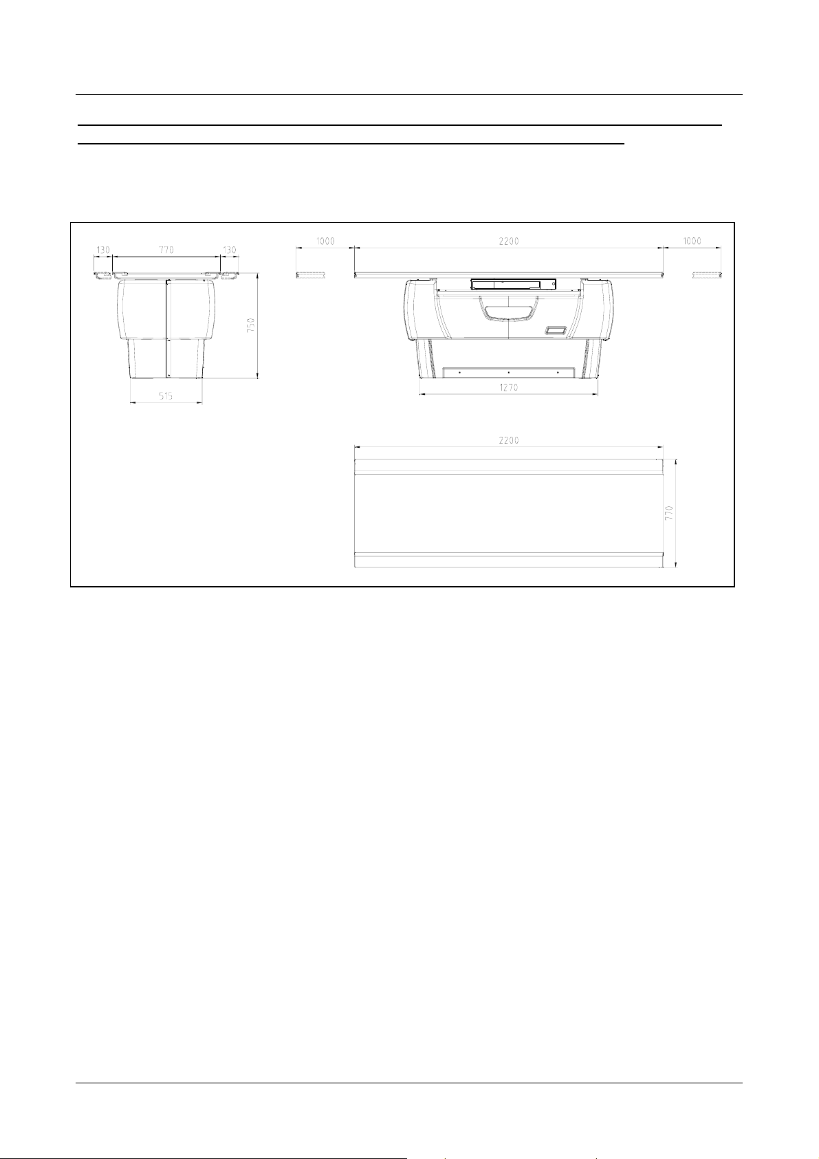
2.4. OVERALL DIMENSIONS
Fig. 2
weight: 260 kg
2.5. PERFORMANCE
2.5.1 MECHANICAL
) Dimensions of table-top 2200x770 mm.
) Distance from table top to plane of FILM: 68 mm with standard POTTER.
) Longitudinal excursion of table top: 1000 mm
) Lateral excursion of table top: 130+130 mm.
) Longitudinal stroke of POTTER: 400 mm.
TECHNICAL AND INSTALLATION MANUAL Pag. 5 di
27

BT MTEBT03
2.5.2. POTTER BUCKY
The BT is fitted (unless requested otherwise) with the standard Potter Bucky with the
following features:
• Motor-driven grid movement, the speed can be adjusted by means of the trimmer R7,
see diagram PTRS001.
• D.F.F. focused anti-scatter grid D.F.F. 120 cm., ratio 1:12, 103 strips per inch. A
different grid can be installed, to the customer specifications.
• Manual stainless steel self-centering cassette holder for X-ray cassettes in sizes from
13x18 cm to 35x43 cm.
• Power supply 24V dc.
• Grid movement starter 24V dc.
• Overall dimensions 570x585x68mm.
• Weight 12.5kg.
2.5.3. TABLE TOP
• Applied part type B to CEI EN 60601-1
• Radiolucent laminate with white surface, contrast media stain-proof
• Maximum weight allowable on table-top: 190 kg
• ATTENUATION EQUIVALENT: less than 1.7 mm Al.
3. ACCESSORIES
TECHNICAL AND INSTALLATION MANUAL Pag. 6 di
27

BT MTEBT03
3.1. ON REQUEST
• Automatic Potter with motor-driven insertion, centering and extraction of the X-ray
cassettes.
• Option for installing a non-standard grid to prevent scatter, with technical specifications
to customer's order.
• Table-top in carbon fiber with attenuation equivalent of about 0.40-0.45 mm Al.
• Compression band.
• Lateral cassette holders for inserting in the side guides on the table-top.
• Pair of handles for patient support, for inserting in the side guides on the table top.
• Head rest with fixing elements for inserting in the guides on the table top.
• Intravenous drip-stand holder.
4. TRANSPORT AND HANDLING
TECHNICAL AND INSTALLATION MANUAL Pag. 7 di
27

BT MTEBT03
1
4.1. PACKAGING
The BT is packed in a wood case with dimensions of 236x98x108 cm, total weight 400Kg,
(with singularly packing)
The box can be moved by crane or transpallet (fig. 3)
4.2. UNPACKING AND HANDLING
The packages can be handled with a crane as illustrated in fig. 3, or with a fork-lift (the
overall weight is 350 kg approx.).
It is important to comply strictly with the recommendations printed on the crates.
Open the box in this sequence 1→ 2→ 3→ 4 → 5 (fig.4)
•
Remove the fixed support.
•
Remove from the box the device.
•
Remove the “Ball in Ball Film”.
•
Fig. 3
P = 400 kg
A
2
I
5
B
Fig. 4
4
3
Î in the event of dispatch by sea, the same case is used as for air transport, with the
difference that the equipment is first inserted in damp-barrier bags.
Î in all other cases, unless specifically requested otherwise by the customer, the
equipment is packaged on a pallet with bubble pack polythene film.
TECHNICAL AND INSTALLATION MANUAL Pag. 8 di
27

BT MTEBT03
5. PRIOR TO INSTALLATION
TECHNICAL AND INSTALLATION MANUAL Pag. 9 di
27

BT MTEBT03
5.1. PREPARING THE ROOMS
1. The minimum useful opening through the doors for accessing the X-ray room must be
cm. 78. If the opening is smaller, the table-top can be removed, in which case the
minimum opening required becomes cm. 74.
2. The ducting needed for the installation is as follows (see fig. 5):
• Bring up to point A (floor outlet) a duct having a minimum diameter of 30 mm from
the X-ray generator.
5.2. CONNECTIONS TO THE GENERATOR
From the generator come up to point A with the following conductors:
a) Multiple cable size 3x1.5mm²
b) Multiple cable size 7x1.5 mm²
c) Earthing connection with green/yellow conductor size 10 mm²
TO THE X-RAY GENERATOR
Fig. 5
TO THE X-RAY GENERATOR
TECHNICAL AND INSTALLATION MANUAL Pag. 10 di
27

BT MTEBT03
6. INSTALLATION
TECHNICAL AND INSTALLATION MANUAL Pag. 11 di
27

BT MTEBT03
AAA
6.1. INSTRUCTIONS FOR ASSEMBLY OF THE EQUIPMENT
AND ACCESSORIES
The unit is delivered dismantled in several parts, as follows
• Technical documentation.
BT horizontal X-ray table structure.
•
Tabletop
•
Carter ABS.
•
6.1.1. MECHANICAL ASSEMBLY
The following list indicates the sequence of operations involved in the positioning and
installation of the equipment.
1. Position the equipment as explained in the pre-assembly instructions, making sure to
keep the Potter centered, along its entire stroke, in relation to the X-ray tube.
2. Mark the position of the holes “A” for attaching the unit to the floor (see fig. 6)
Fig. 6
A
TECHNICAL AND INSTALLATION MANUAL Pag. 12 di
27

BT MTEBT03
A
3. Move the equipment aside and drill suitable holes for the screw anchors you are using,
depending on the type of floor. The screw anchors provided with the equipment require
a hole 12 mm in diameter. Insert the anchors and bring the equipment into position
once again.
4. Before definitively fixing the caisson for the table top in place, check that it is perfectly
level and centered in relation to the X-ray tube. To get the leveling use the special
thickness on equip.
5. Fix the bucky table base to the floor.
6. Remove the screws “A” fig. 7 to release the potter and table support
Fig. 7
A
TECHNICAL AND INSTALLATION MANUAL Pag. 13 di
27

BT MTEBT03
7. Fit the bottom ABS cover in place and fix with screws (fig. 8)
8. Fit the top ABS cover in place and fix with screws (fig. 9)
Fig. 8
Fig. 9
TECHNICAL AND INSTALLATION MANUAL Pag. 14 di
27

BT MTEBT03
9. Dismantle the table-top by removing the 4 screws (Pos. A fig.10) on the supporting
element for attaching the two side guides . The supporting element pos. B fig.10 can be
removed either from the right or from the left, depending on the space available for its
re-assembly.
A
B
A
Fig. 10
10. Fit the table top in place again, proceeding as in item 9 but in reverse order.
11. Check the proper operation of the table-top brakes.
12. Check the proper operation of the Potter.
TECHNICAL AND INSTALLATION MANUAL Pag. 15 di
27

BT MTEBT03
6.1.2. ELECTRIC CONNECTIONS
Referring to the diagram Block BT “BTFZ10A”:
The system is connected to the mains power supply by means of the connector M1 on the
BTFZ10A panel, using the following pin/out:
M1 TERMINAL BLOCK (BTFZ10A panel)
INPUT 220/240 Vac POWER SUPPLY PHASE FROM X-RAY GENERATOR
1
INPUT 220/240Vac POWER SUPPLY NEUTRAL FROM X-RAY GENERATOR
2
GND
3
The system is connected to the X-ray generator by means of the CN8 terminal block on
the BTFP02A board using the following pin/out:
CN8 TERMINAL BLOCK (BTFP02A board)
OUTPUT GRID START CONTACT
1
OUTPUT GRID START CONTACT
2
OUTPUT X X-RAY CONTACT
3
OUTPUT X X-RAY CONTACT
4
5
6
NC
NC
The power and control lines for the X-ray commands are connected to the X-ray generator
by means of the cable prepared during the pre-installation operations. The equipotential
ground node must be connected to the general ground GND node in the X-ray room. The
other electric connections form part of the system wiring, so it is not necessary to provide
further wiring during the installation phase.
The tube stand device STATIX is connected to the BT by connector CN1 on the BTFP02A
board according to the BTFZ10A wiring diagram and using the wires provided.
IMPORTANT!
• The electric system for powering the equipment must be in compliance with the current
regulations applicable to the country where the equipment is installed.
• The manufacturer accepts no liability for any failure to comply with the above
recommendation.
TECHNICAL AND INSTALLATION MANUAL Pag. 16 di
27

BT MTEBT03
7. MAINTENANCE AND REPAIRS
TECHNICAL AND INSTALLATION MANUAL Pag. 17 di
27

BT MTEBT03
7.1. MAINTENANCE
Before taking any action, it is compulsory for the maintenance technician to stop
the equipment in such conditions that it cannot be started again without his consent
(equipment disabled).
There are cases in which the maintenance technician has to verify the results of certain
operations he has performed or to proceed with a fault-finding session while the equipment
is running. In such cases, specific and indispensable instructions must be given to ensure
that:
• The operator at the controls and the maintenance technician can see each other so that
their communications are easy and unequivocal.
• The operator must act according to the instructions received from the maintenance
technician.
• All maintenance must be done under conditions of adequate lighting.
The maintenance technician must be informed of the exact function of all parts of the
equipment. In the event of any doubts, he must consult the RELEVANT sections of this
manual; he must also pay attention to the signal labels attached to the equipment itself.
Any welding operations on the equipment are likely to cause damage to the
instrumentation and to the electrical and/or electronic devices if these are powered. It is
therefore advisable in this case to disconnect the equipment electrically.
For the first 6 months, and every 12 months thereafter, make the following checks and
adjustments:
⇒ After removing the ABS cover (fig. 8 and fig. 9 par.6.1.1) accurately clean the inside
of the equipment and check that the screws that hold it attached to the floor are tight.
⇒ Check that the moving parts are working properly and lubricate as necessary.
⇒ Check the preservation of the electrical and earthing connections.
⇒ Remove the table-top and accurately clean all the upper parts of the appliance and
lubricate (fig.10 par.6.1.1). Remove any remains of contrast medium from the table
top and Potter cover.
⇒ Potter bucky, clean and lubricate the moving parts (greed support). Remove any
foreign bodies, such as lead numbers and letters.
⇒ Check and, if necessary, adjust the electromagnetic brakes.
⇒ Check the state of wear on the rubber end-of-stroke shock absorbers.
⇒ Check the optical switch brake alignment and function.
⇒ Check and, if necessary, adjust the bearings and their tightness.
Re-install the table-top and any covers that have been removed and check the general
operation of the equipment. Make a mechanical and radiographic test.
TECHNICAL AND INSTALLATION MANUAL Pag. 18 di
27

BT MTEBT03
8. SPARE PARTS
TECHNICAL AND INSTALLATION MANUAL Pag. 19 di
27

BT MTEBT03
TECHNICAL AND INSTALLATION MANUAL Pag. 20 di
27

BT MTEBT03
TECHNICAL AND INSTALLATION MANUAL Pag. 21 di
27

BT MTEBT03
TECHNICAL AND INSTALLATION MANUAL Pag. 22 di
27

BT MTEBT03
TECHNICAL AND INSTALLATION MANUAL Pag. 23 di
27

BT MTEBT03
9. WIRING DIAGRAMS
TECHNICAL AND INSTALLATION MANUAL Pag. 24 di
27


A
B
C
D
E
CN2
6
4 4
CN1
1
2
3
4
5
6
4
3 3
CN7
- +
3
D4
1
12
C1
+
2
4700µF 63V
5
4
3
2
1
+24Vcc
+24Vcc
D2
1 2
D3
1N4007
8
1
3
6
1 2
2K2 1/4W
RL1
4
2
5
7
R1
12
D5
1 2
BYW29E-150
1
12
D19
2 2
JP1
12
R11
2K2 1/4W
JP2
3
2
1
+24Vcc
1
2
3
1
2
3
JP3
a termini di legge è severamente vietato riprodurre o comunicare a terzi il contenuto
del presente disegno
+24Vcc
8
15
7
14
6
13
5
12
4
11
3
10
2
9
1
1
2
CN3
3
4
1
2
CN4
3
4
2
CN6
1
1
CN5
2
CN12
1
2
3
CN8
4
5
6
1 1
-
2
C-1/2
1
A
REV. ZONA DESCRIZIONE VARIAN TI
Rimosso CN11, CN13, RL6 , D1, D17, D18, R10, F1, F2
AGGIUNTO RELE' RL6 PIU ' DIODI
PRIMA EMISSIONE
-
B
Disegnato
C
S.B.
F.B.
S.B.
F.B.
S.F.0
F.B.
Controll. Approv. Data
S.B.
S.B.
S.B.
25.10.05
05.05.1998
Title
29.05.01
BT INTERFACE
Size Document Number Rev
A4
BTFS02A
D
Sheet of
1 1
E
2

A
B
C
D
E
1
CN6
CN5
2
3
4
1
2
3
4
2
1
1
2
8
15
7
14
6
13
5
12
4
11
3
10
2
9
1
15
14
13
12
11
10
CN3
CN4
8
7
6
5
4
3
2
9
1
4 4
M1
FASE
220-240Vac POWER
LINE
SUPPLY
NEUTRAL
3 3
2 2
1
2
F1
2A
THERMAL
OVERLOAD
TR1
200Vac
220Vac
240Vac
1 CN3
2 CN3
STXP04A BOARD
F2
80VA
18Vac
20Vac
F3
170VA
24Vac
27Vac
BTFP02A2
2A
5A
BOARD
6
5
4
CN2
3
2
1
1
2
3
CN1
4
5
6
CN12
3 BLUE (-0Vdc)
1 BROWN (+10-30Vdc)
4 BLACK OUT (250mA MAX)
RECEIVER
3 BLUE (-0Vdc)
1 BROWN (+10-30Vdc)
SENDER
SEE POTTER
SCHEMATIC
0 Vac
24 Vac
GRID START
GRID START
X X-RAY CONTACT
X X-RAY CONTACT
P1
UNLOCK
BRAKE
SBLOCCO
FRENO
12
ET1
12
ET3
ET5
1 2
BRAKE
POTTER
FRENO
POTTER
PHOTOCELLS
CONTROL BRAKE
12
ET2
TRASV.
AND LONG.
TABLE TOP
12
ET4
POTTER
STATIX
1
CN7
1
2
3
CN8
4
5
6
1 1
2
1
PRIMA EMISSIONE
REV. ZONA DESCRIZIONE VARIANTI
A
B
-
C
GRID START
GRID START
X X-RAY CONTACT
X X-RAY CONTACT
X-RAY GENERATOR
S.B.
S.F.0
F.B.
Disegnato
Controll. Approv. Data
D
25.10.05
a termini di legge è severamente vietato riprodurre o comunicare a terzi il contenuto
del presente disegno
Title
DIAGRAM BLOCK BT
Size Document Number Rev
A3
BTFZ10AA
Sheet of
E
1 1
0
 Loading...