

Page 1
T H E R M A L & T H E R M A L T R A N S F E R
L A B E L P R I N T E R S
models
smart
smart
smart smart
2
200
22
000
0000
0/280
00
/280
/280/280
USER MANUAL
italora
Italora S.r.L. Largo Guastalla 7 - 20082 Binasco - (Milano) - Italy
phone +39.02.90092074 - fax +39.02.9055461
www.italora.it
rev. 07.13
Page 2

CONTENTS
1. GENERAL DESCRIPTION ......................................................................................................................... 3
2. TECHNICAL SPECIFICATIONS ............................................................................................................... 3
3. UNPACKING .............................................................................................................................................. 4
4. EXTERNAL DESCRIPTION ...................................................................................................................... 4
5. MAIN COMPARTMENT DESCRIPTION ................................................................................................. 4
6. INCOMING INSPECTION ......................................................................................................................... 5
6.1. LABEL FORMAT SET UP PROCEDURE ................................................................................ 5
7. PRINTING MEDIA DESCRIPTION .......................................................................................................... 6
7.1 PAPER SPECIFICATIONS ......................................................................................................... 6
7.2. THERMAL RIBBON SPECIFICATIONS ................................................................................. 6
8. THERMAL RIBBON AND LABEL ROLL REPLACEMENT .................................................................. 6
8.1. THERMAL RIBBON REPLACEMENT .................................................................................... 6
8.2. LABEL ROLL REPLACEMENT ............................................................................................... 6
8.2.1. DISPENSING MODE .............................................................................................................. 6
8.2.2. STRIP FORM MODE .............................................................................................................. 6
8.2.3. REWINDING MODE .............................................................................................................. 7
9. CONNECTION TO HOST COMPUTER .................................................................................................... 7
10. MAINTENANCE ....................................................................................................................................... 8
10.1. CLEANING ............................................................................................................................... 8
11. TROUBLE SHOOTING ............................................................................................................................ 8
11.1. NO LABELS FEEDING ........................................................................................................... 8
11.2. INCORRECT LABEL ALIGNMENT ...................................................................................... 8
11.3. PAPER SLIDES TO RIGHT SIDE ........................................................................................... 9
11.4. PRINTING WITH PATCHES MISSING ................................................................................. 9
11.5. BLANK LABELS ..................................................................................................................... 9
11.6. POOR PRINTING CONTRAST ............................................................................................... 9
11.7. LABELS ARE NOT CORRECTLY PEELED OFF ................................................................. 9
12. HARDWARE NOTES ............................................................................................................................... 9
12.1. HOW TO CHECK ELECTRONIC BOARDS .......................................................................... 9
12.2. ELECTRONIC BOARDS REPLACEMENT ........................................................................... 9
12.3. PRINT HEAD PROTECTION FUSE REPLACEMENT ......................................................... 9
12.4. THERMAL PRINT HEAD REPLACEMENT ......................................................................... 10
12.5. DRIVE BELT REPLACEMENT .............................................................................................. 10
13. PICTURES ................................................................................................................................................. 10
14. PART LIST AND RELEVANT PICTURES ............................................................................................. 16
Features and specifications are subject to change without notice
S2000/280
2
Page 3

smart
smart
smartsmart
2000/
2000/280
2000/2000/
280
280280
GRAPHIC LABEL PRINTERS
1. GENERAL DESCRIPTION
These units offer an accurate and high quality
printing moreover a formatting capability of 5 layouts
in Flash memory. They can operate in dispensing
mode, because of the inside mechanism for peeling
and rewinding, or in strip form.
Resident Bar Codes are dispensed at high
Printers of this family have obtained the IMQ approval according to European Standard EN 60950.
speed and the eight character generators with eighty
magnifications give a wide range of fonts.
The inside label unwind holder offers an
autonomy of 1500 labels (106 x 70 mm), the modular
design of these printers offers an easy service as well
for electronic boards as for mechanics maintenance.
2. TECHNICAL SPECIFICATIONS
PRINTING
Method: Direct Thermal and Thermal Transfer
8 dots/mm, 832 dots/line
Print width: 104.0 mm
Print speed: up to 120 mm/s
X/Y positioning of texts and bar codes
Texts and bar codes printed in four orthogonal directions
Lines, boxes, shadow and reverse printing
Graphic and logos: bit image mode
Bar Codes: EAN8, EAN13, 2/5, 2/5 I, 3/9, 2/7, DUN-14/16,
UPC-A, UPC-B, UPC-E, CODE 128, EAN 128,
EAN13+ADDON
Automatic Check Digit computation
Wide/narrow ratio full programmable
Half, standard and double density
Height programmable
Suppression of human readable characters
Batch printing: up to 9999 labels
Layouts: 5 programmable in Flash, 50 fields each
Up to 10 protection levels for variable data printing
4 up/down 16 digits counters
Real Time Clock
Black intensity adjustable via software
Print button for last label repeating
THERMAL HEAD TEMPERATURE CONTROL
DATA TRANSFER INTERFACE
RS232: serial parameters settable by sw
USB
HANDSHAKE PROTOCOL
SW : XON/XOFF
HW : DTR
DATA TRANSMISSION
ASCII format
CHARACTER GENERATORS
Micro (fixed matrix) 5x5
Standard (fixed matrix) 7x5
Draft (fixed matrix) 8x13
Big (fixed matrix) 16x24
New Century (proportional) 45
Arial (proportional) 32
Motor (fixed matrix) 32x48
Compact (proportional) 19
Magnifications 9x9
CHARACTER SIZES
0.62 x 0.66 mm minimum
36.00 x 57.00 mm maximum
MEMORY
32 – bit RISC microprocessor
4 MB flash
8 Mb RAM
DETECTORS
For end of paper and feeding synchronism
For end of thermal ribbon
PRINT MEDIA
Labels, tags and continuous strips
LABEL SIZES
Width: 30 mm min., 110 mm max
Length: 10 mm min.
303 mm max
Key: width min.: 2 mm
depth min.: 7 mm starting 2 mm min.
from the inner edge
ROLL SIZES
Width: 30 mm min., 110 mm max
Outer diameter: 150 mm max
Core diameter: 38 mm min.
THERMAL RIBBON
Base polyester film
Outer diameter: 58 mm max, length 220 meters
Width: 35 mm min., 110 mm max
Core diameter: 25.4 mm
PRINTER DIMENSIONS
Height: 200 mm; Depth: 440 mm
Length: 235 mm; Weight: 17 Kg
POWER REQUIREMENTS
Voltage: 220/240 Vac; 50-60 Hz
on request 110 Vac
ENVIRONMENT
Operating temperature: 0°/ 40° C
Storage temperature: -20°/60° C
Humidity: 10% - 95% non-condensing
OPTIONS
Label taken sensor
Guillotine
ETIK wysiwyg label editor Windows based
S2000/280
3
Page 4
3. UNPACKING
Open the box and check the content :
a) italora label printer model
smart 2000/280
b) power cable
4. EXTERNAL DESCRIPTION
c) roll of labels
d) roll of thermal ribbon
e) printing tests
f) serial cable RS232 and USB cable
g) CD Rom with manuals and Etik Light
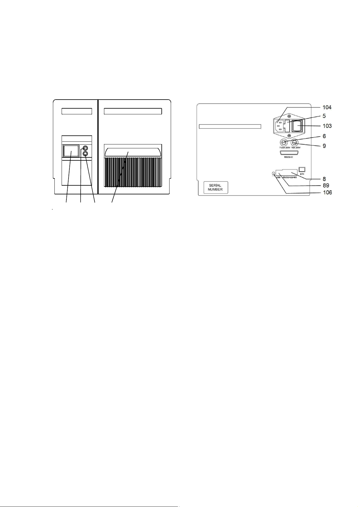
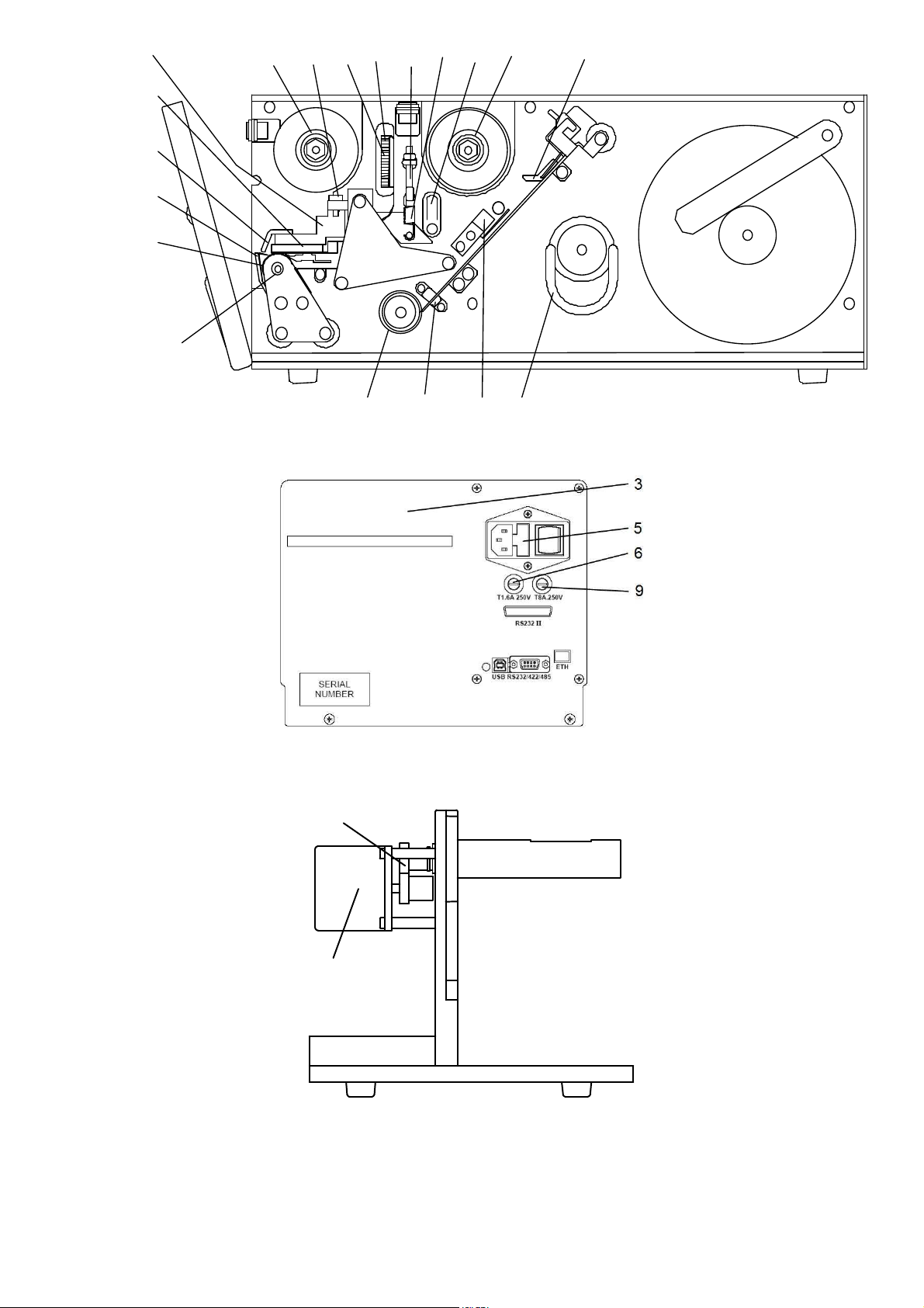
1 100 101 102
PICTURE 3
1: manual printing push button
100: red led => lit at POWER ON
101: green status led =>
- lit: ON-LINE
- blinking: end of paper
end of ribbon
- off: syntax error (push printing button
to restart)
head temperature control active
102 label output
5: 2 fuses 2AT (main)
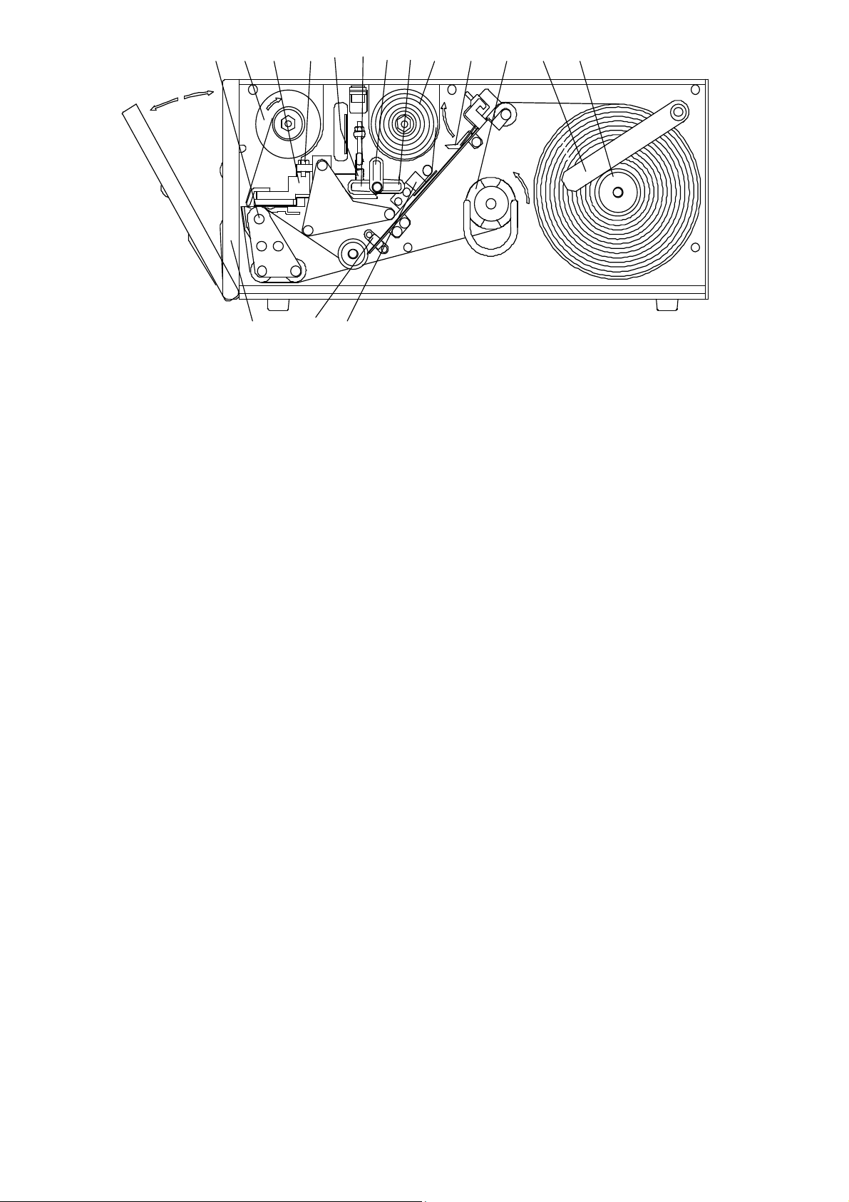
5. MAIN COMPARTMENT DESCRIPTION
(see following picture)
10 - photosensor for end of roll and label
synchronisation
15 - rewinding shaft with adjusting clutch
18 - print head position fine adjustment
21 - rubber feeding roll
23 - print head assembly pressure spring
25 - lock / unlock lever
25a - working position
25b - open position
25c - cleaning position
PICTURE 4
5: 2 fuses 2AT (main))
6: 1 fuse 1.6AT (logic
8: serial port
9: fuse 8AT (thermal head)
89 USB port
103: main switch
104: power cord plug
106 trimmer for black intensity fine adjust
- clockwise = more intensity
- anticlockwise = less intensity
29 - thermal ribbon rewinder
30 - thermal ribbon stock
32 - label guide arm
33 - pressure clip
35 - front cover
45 - label unwind holder
48 - photosensor for end of thermal ribbon
105 - print head assembly
S2000/280
4
Page 5
21 29 105 18 23 25b 25a 30 33 15 32 45
35 10 48
25c
PICTURE 6
6. INCOMING INSPECTION
* Open the main compartment
* Check the presence of the label roll and of the
thermal ribbon roll
* Check the correct pinout of the serial I/O Cannon 9
pins female connector (or of the USB connector) and
connect the printer to the computer.
* For further details see chapter "Connection to Host
Computer".
* Check the voltage on the name plate next to the
power receptacle.
NOTE: Printer retains the label length and the backing paper transparency in permanent memory.
In case of change of print media see the following paragraph.
6.1. LABEL FORMAT SET UP PROCEDURE
(see pictures 7 and 8)
* Connect the power cable to a grounded power line
* Lift the printhead down by rotating the
lever #25a.
* Switch the main switch on (rear panel)
RED and GREEN leds ON mean operating
conditions.
* Push the PRINT BUTTON, you will get a printing
test with the FIRMWARE release information.
* Sending data from the computer you will get the
first printing.
* Push the PRINT BUTTON to get the last
printing again; the printer keeps the information
of the last printing until next data arrive.
The printer retains the label length and the backing
paper transparency in permanent memory. If changing
label format or print media type you have to use the
following procedure to update the values:
1 - Switch the printer off.
2 - Lift the printing head up by rotating lever #25b.
3 - Thread the web between the feed roller and the
printig head #21,105.
4 - Check web has been rightly positioned under the
label photosensor #10.
5 - Lift the printing head down by rotating the
lever #25a.
6 - Switch the printer on while pushing the print
button.
7 - Printer ejects some labels (depending on their
length) and stores the values of the media.
8 - Release the print button.
9 - The green led lit and the printer is ready to
work.
For further information about media options see chapter 7 and the paragraph "Labels, tags and
continuous media printing" of the PROGRAMMING MANUAL.
S2000/280
5
Page 6

7. PRINTING MEDIA DESCRIPTION
- Fasson Fastransfer Extra - S470
7.1 PAPER SPECIFICATIONS
White coated glossy printing paper
- weight: 65 ÷ 90 g/mq (ISO536)
- caliper: 0,075 ÷ 0,083 mm (ISO534)
ADHESIVE SPECIFICATIONS
- peel adhesion(90° C): 430 N/m
- service temperature: -20° C ÷ + 70° C
LINER SPECIFICATIONS
- BG 40 brown, supercalendered glassine
- weight: 65g/mq (ISO536)
- caliper: 0.057 mm (ISO534)
- transparency: 45%
TAGS AND CONTINUOUS STRIPS
- weight: 200 g/mq max
SUGGESTED MODELS
- Fasson Fasthermal NT
- Kanzaki KPT 86-H
- Fasson Fastransfer MP - S470
LABEL AND TAGS DIMENSIONS
See Chapter 2
7.2. THERMAL RIBBON SPECIFICATIONS
- film thickness 4.5 ÷ 6 micron
- core diameter: 25.4 mm
- outer diameter: 58 mm max
- width: 35 mm min/ 110 mm max
- length: about 220 meters (58 mm DIA. max)
- ink coating outside
SUGGESTED MODELS
- TOIKO C 250 (matt paper)
- TOIKO CR 150 (glossy paper and polypropylene)
- TOIKO R 300 (plastic media)
STORAGE
Keep labels and ribbons in a dry place at temperature
not over 40° C and not exposed to direct sun light.
8. THERMAL RIBBON AND LABEL ROLL REPLACEMENT
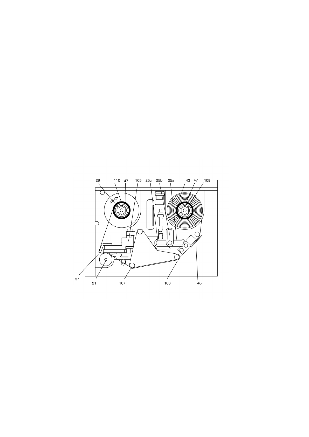
8.1. THERMAL RIBBON REPLACEMENT
(see picture 7)
Open side of printer.
Remove the used roll. Remove the core #47 from the
shaft and put it on the rewinder #29.
By rotating the lever #25b, lift the printing head #105
from the feed roller #21, setting the movement of
the ribbon free.
Slide new ribbon #43 onto shaft and thread it under
the ribbon photosensor #48 and the threaders
#108,107 and 37 and up round to the rewinder #29.
Attach the ribbon leader with label/tape to core #47.
Return head lever to closed position #25a.
Close side of printer.
8.2. LABEL ROLL REPLACEMENT
In case of changing of label format or printing media type, remember to follow the "Label format set up
procedure" shown on paragraph 6.1.
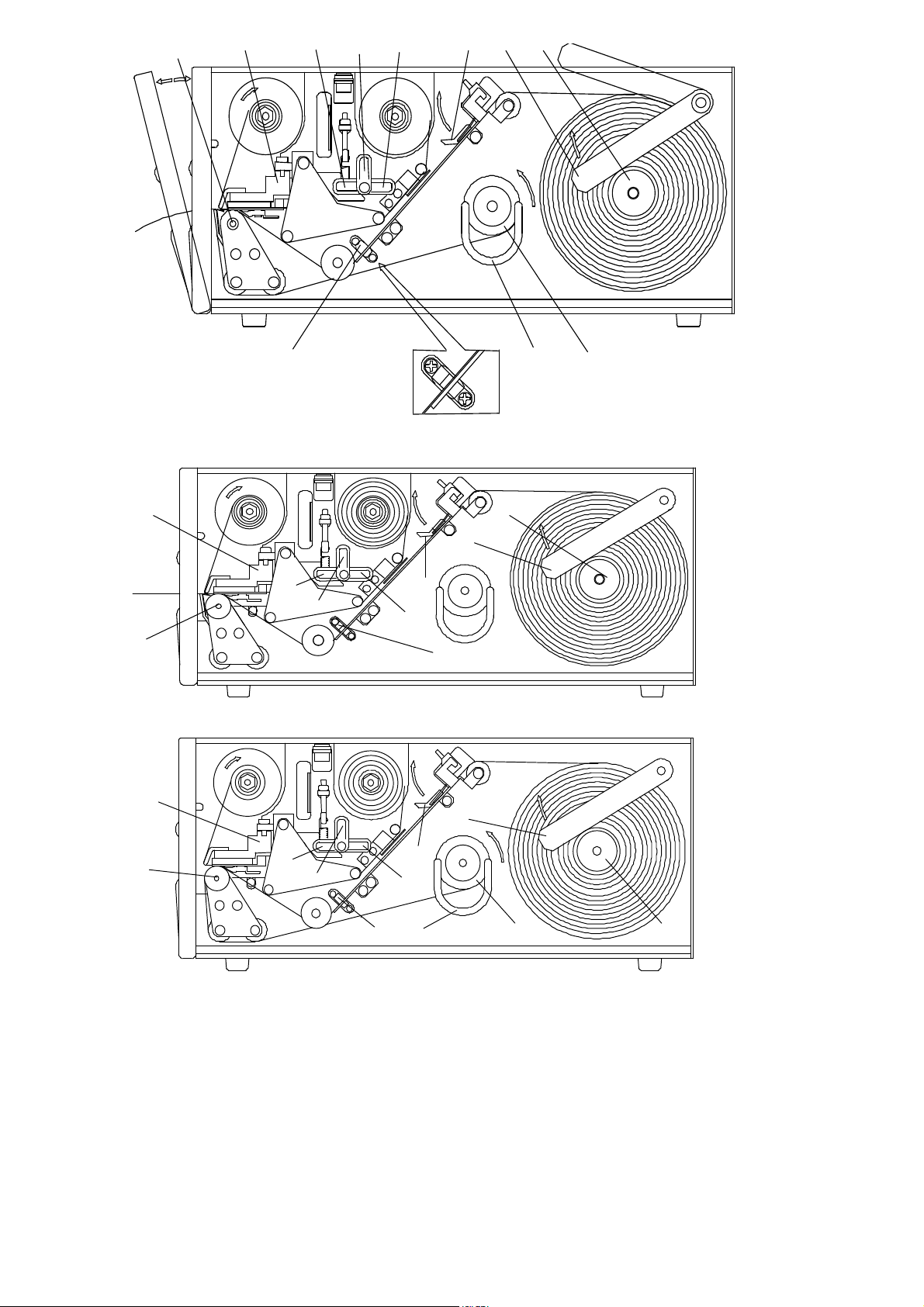
8.2.1. DISPENSING MODE
(see picture 8)
Open side of printer.
Remove the empty label roll.
Lift guide arm #32.
Insert new label roll onto roller #45
Bring the guide arm #32 down and push it tightly
against the side of the label roll.
By rotating the lever #25b, lift the printing head #105
from the feed roller #21, setting the movement of
labels and ribbon free.
Remove clip #28 from the rewinding shaft #15.
Remove backing paper from the rewinding shaft.
Remove the first 50 centimetres from liner of the new
roll labels.
Hold pressure clip #33 up and feed the liner through
the path, slide it on the rewinder unit #15 and
fasten it with the clip holder #28.
Turn the rewinder to stretch the paper.
Turn head lever back to closed position #25a.
Check paper has been rightly positioned under
the label photosensor #10.
Check pressure clip #33 has been positioned between
centre and outer side of the label.
Close side of printer.
8.2.2. STRIP FORM MODE
S2000/280
6
Page 7
(see picture 9)
Open side of printer.
Remove the empty label roll.
Lift up the guide arm #32.
Insert new label roll onto roller #45
Bring the guide arm #32 down and push it tightly
against the side of the label roll.
By rotating the lever #25b, lift the printing head #105
from the feed roller #21, setting the movement of
labels and ribbon free.
8.2.3. REWINDING MODE
(see picture 10 and 11)
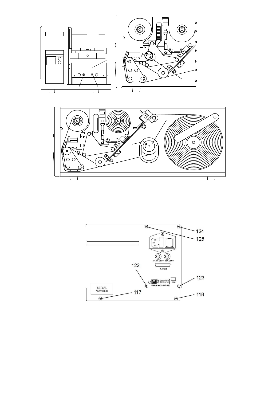
Is necessary to rewind printed labels inside to remove
the plate #20, turning the screws #139,140 out.
Open side of printer.
Remove the empty label roll.
Lift guide arm #32.
Insert new label roll onto roller #45
Bring the guide arm #32 down and push it tightly
against the side of the label roll.
By rotating the lever #25b, lift the printing head #105
from the feed roller #21, setting the movement of
labels and ribbon free
Hold pressure clip #33 up and feed the paper through
the path.
Turn head lever back to closed position #25a.
Check paper has been rightly positioned under
the label photosensor #10.
Check pressure clip #33 has been positioned between
centre and outer side of the label.
Close side of printer.
Remove clip #28 from the rewinding shaft #15.
Hold pressure clip #33 up and feed the paper through
the path, slide it on the rewinder unit #15 and
fasten it with the clip holder #28.
Turn the rewinder to stretch the paper.
Turn head lever back to closed position #25a.
Check paper has been rightly positioned under
the label photosensor #10.
Check pressure clip #33 has been positioned between
centre and outer side of the label.
Close side of printer.
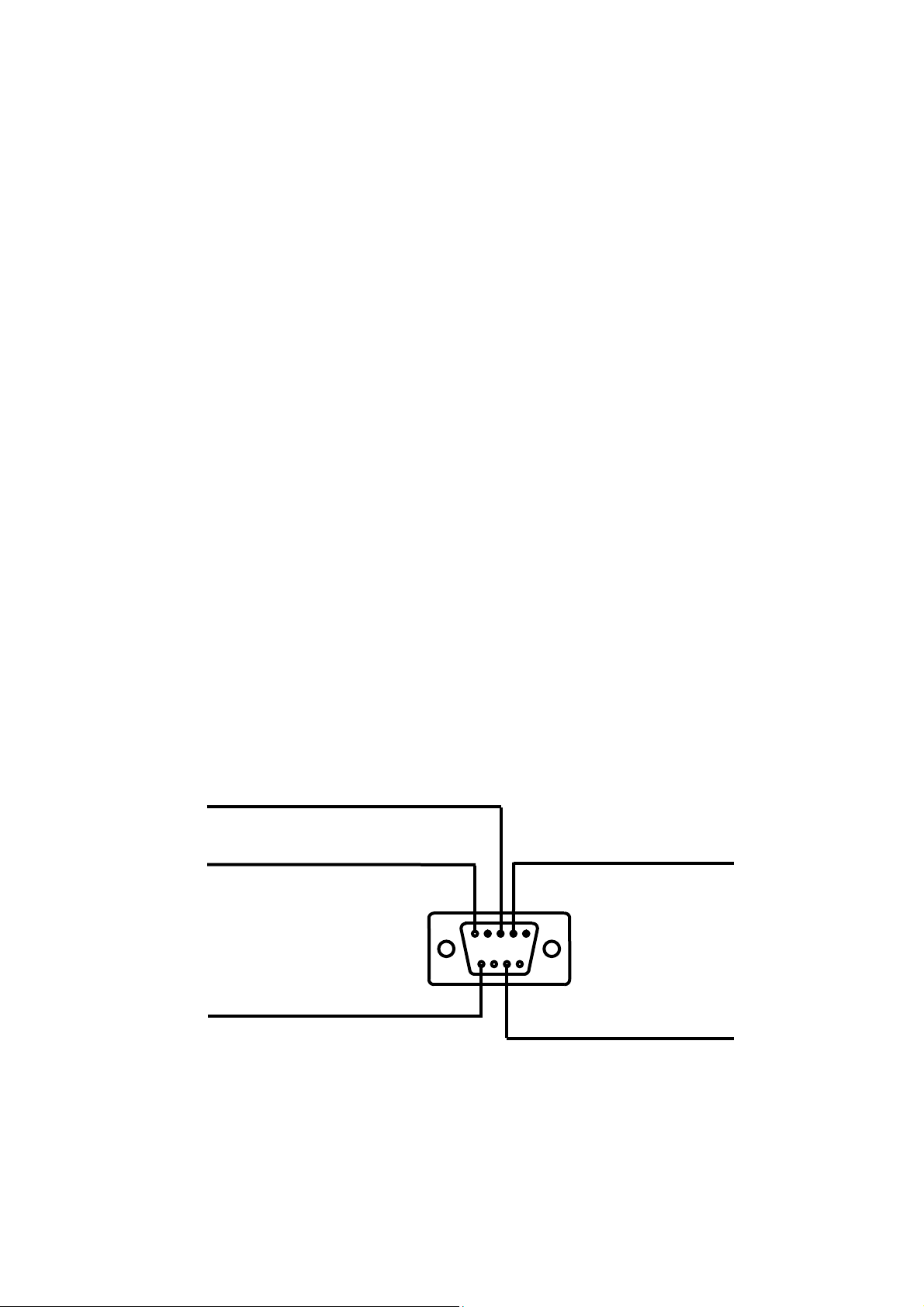
9. CONNECTION TO HOST COMPUTER
smart 2000/280 printers have a RS232 hardware interface. Provided on board connector is a Cannon 9 pins
"DB" female cabled as shown in the following pictures.
3 - Rs232 Tx
5 - LOGIC GROUND (GND)
2 - Rs232 Rx
9 - +5V
7 - Rs232 RTS
Connection to personal computer may be done in different ways:
S2000/280 7
Page 8
COMPUTER
PRINTER
COMPUTER
PRINTER
COMPUTER CONNECTOR - 9 PIN
2
3
8
5
COMPUTER CONNECTOR:
-using sw protocol XON/XOFF:
short together PINS 7-8 and 1-4-6.
-using hw protocol CTS/RTS:
short together PINS 1-4-6.
10. MAINTENANCE
WHEN NOT IN USE:
- SWITCH OFF POWER
- ALWAYS LIFT UP THE PRINTER HEAD
3 TX
2 RX
7 RTS
5 GND
COMPUTER CONNECTOR - 25 PIN
3
2
5
7
COMPUTER CONNECTOR:
-using sw protocol XON/XOFF:
short together PINS 4-5 and 6-8-20.
-using hw protocol CTS/RTS:
short together PINS 6-8-20.
3 TX
2 RX
7 RTS
5 GND
10.1. CLEANING
Print Head
- Turn the power off.
- Wait until thermal head cools down.
- Lift the print head by using the lever on position 25c
- Remove labels and thermal ribbon.
WARNING: never use hard tools as this may damage the print head.
Rubber feeding roll: use alcoholic detergents.
Photosensor: use a soft brush.
Metallic and plastic parts: use a soft cloth with
- Moisten a cotton cloth with denatured alcohol.
-Polish the below side to remove incidental adhesive
traces or parts of labels.
- Wait until dry before use
Removing adhesive traces or parts of labels: use
alcoholic detergents. Be careful the liquid does not
drip on the electronic compartment.
water-based detergent (weak).
11. TROUBLE SHOOTING
11.1. NO LABELS FEEDING
Four situations may occur.
a) RED led is OFF, check (pict.3,#100):
- main voltage
- main switch (pict.4,#103) ON.
- main connector (pict.4,#104) plugged in
- main fuses (pict.4,#6) intact.
b) RED led is ON, GREEN STATUS led is BLINKING
check:
- label roll is not used up.
- paper position under the photosensor (pict.8,#10)
c) RED led is ON, GREEN STATUS led is BLINKING
check:
- thermal ribbon is not used up .
- thermal ribbon position under the photosensor
(pict.7,#48) .
d) RED led is ON, GREEN STATUS led is OFF:
- head temperature control active, printer stops until
temperature has fallen to normal values.
11.2. INCORRECT LABEL ALIGNMENT
Make sure that:
- print head is closed (pict.6,#25a)
- paper position under the photosensor (pict.8,#10)
- backing paper is correctly rewound (pict.6,#15)
- pressure clip (pict.6,#33) is positioned
between centre and outer side of the label.
- guide arm (pict.6,#32) is tightly pushed against
the side of the label roll.
See also "Label format set up procedure" paragraph
6.1
S2000/280 8
Page 9

11.3. PAPER SLIDES TO RIGHT SIDE
Check whether:
- pressure clip (pict.6,#33) is positioned between
- guide arm (pict.6,#32) is closely positioned against
the side of the label roll.
centre and outer side of the label.
11.4. PRINTING WITH PATCHES MISSING
Check whether:
- thermal print head needs cleaning
(chapter 10)
- thermal ribbon unwinds correctly.
11.5. BLANK LABELS
Check whether
- the fuse (8AT) on the back panel has blown
- the print head connector is correctly plugged in
- there are creases on the rewound thermal ribbon. If
so, turn the nut (pict.7,#110) clockwise, in order to
increase the rewinding torque (a quarter of a turn
max) while holding the roller (pict.7,#29) still.
- thermal ribbon is correctly positioned, opaque
surface on the label side .
(pict.13,#112) with polarity key up.
11.6. POOR PRINTING CONTRAST
- See printer rear panel.
- turn the print head screw (pict.4,#106) for
temperature fine adjustment :
clockwise to make print darker.
anticlockwise to make print lighter.
Otherewise use the software command ?77& (see
Programming Manual).
BEWARE: continual high operating temperature of
thermal head may reduce its working life and may also
fuse the ribbon .
11.7. LABELS ARE NOT CORRECTLY PEELED OFF
(DISPENSING MODE)
- Make sure the label adhesive respects the
specifications (see chapter 7).
- Turn the nut (pict.16,#41) clockwise, in order to
while holding the roller (pict.16,#15) still.
BEWARE: excessive torque may cause incorrect
labels alignment.
increase the rewinding torque (a turn max)
12. HARDWARE NOTES
12.1. HOW TO CHECK ELECTRONIC BOARDS
- First unplug the power cable from the printer.
- open side of printer
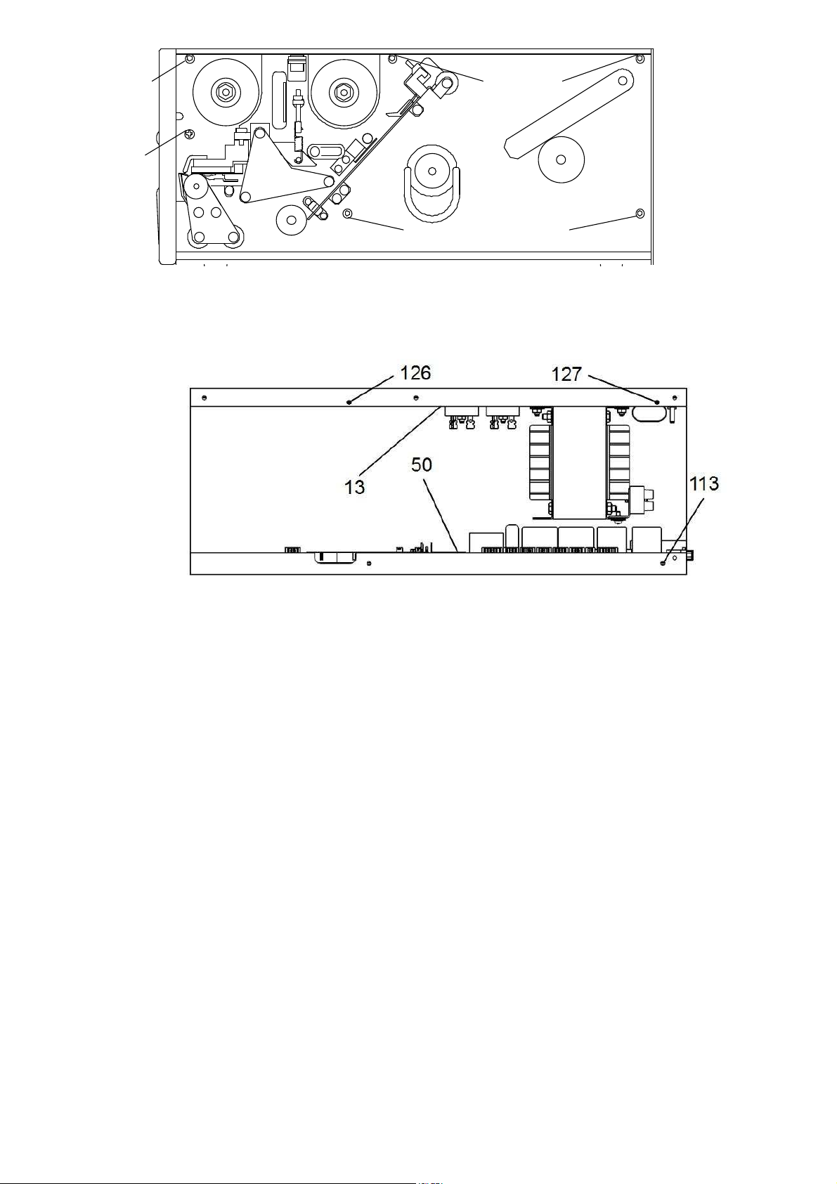
- remove the 6 side screws (pict.19,#114,115,116,
119,120,121)
- turn the 2 rear panel screws (pict.18,#117,118) out.
- pull carefully off the electronic cabinet from the
printer chassis and unplug the following connectors
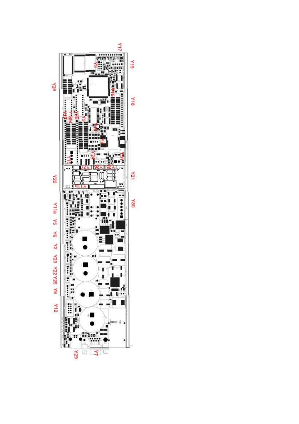
from CPU board (pict.21).
12.2. ELECTRONIC BOARDS REPLACEMENT
Unplug the following connectors from the CPU board
(pict.21):
Y7 = serial interface
Y30 = power supply
- turn the 4 rear panel screws
(pict.18,#122,123,124,125) out.
Y2 = ribbon photosensor
Y3 = leds and push button
Y4 = stepping motor
Y5 = label photosensor
Y9 = thermal head
- disconnect the ground cable turning the chassis nut
out.
- turn the lock screw (pict.20,113) out and pull
out the CPU board (pict.20,#50).
- unplug the fuses connectors and the main switch
connector.
- turn the 2 lock screws (pict.20,#126,127) out.
- pull the power supply (pict.20,#13) out.
12.3. PRINT HEAD PROTECTION FUSE REPLACEMENT
- Thermal print head is protected by an 8 A timed fuse (pict.4,#9).
S2000/280 9
Page 10
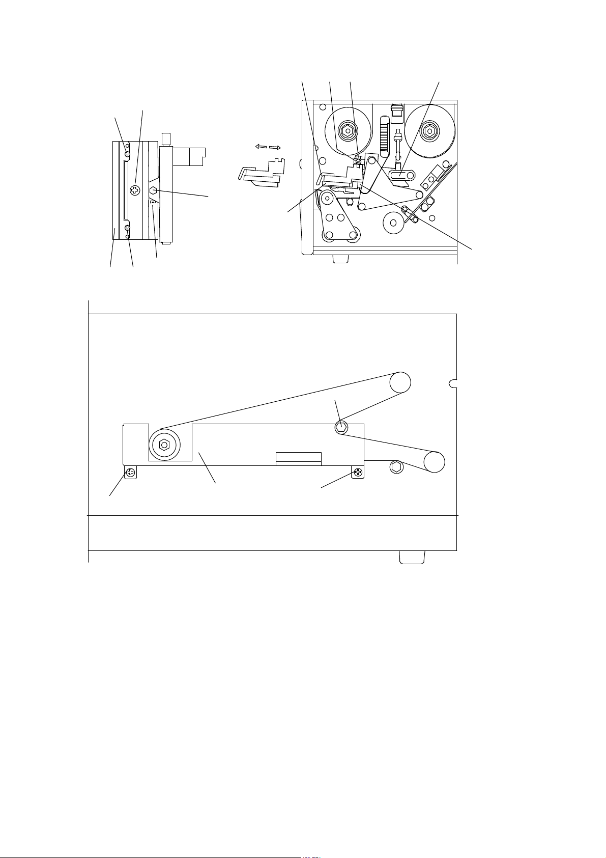
12.4. THERMAL PRINT HEAD REPLACEMENT
(see picture 27)
1 switch the printer off .
2 unplug the flat connector #112 from the print head.
3 lift print head by rotating the lever #25c..
4 turn the screw #130 out.
5 remove the adjusting nut #18.
6 pull out the print head and dissipater assembly
from the pivot pin.
7 turn the screw #138 out and remove the print head
#26 from the dissipater.
8 replace thermal head and run back steps 7 to 2.
WARNING: pay attention to plug in correctly the
irreversible damage to the print head functionality
(pict. 13)
9 in case of printing quality problems, loosen the
screw #130 and turn slowly the adjusting nut in or
out #18, for the best printing quality, finally lock
the screw #130.
10 in case of creases on the rewound thermal ribbon,
loosen the screws #128,129 and adjust the plate
#37 in order to obtain a correct parallelism and
flatness on the rewound ribbon; finally lock the
screws #128,129 .
thermal head connector, wrong connection causes
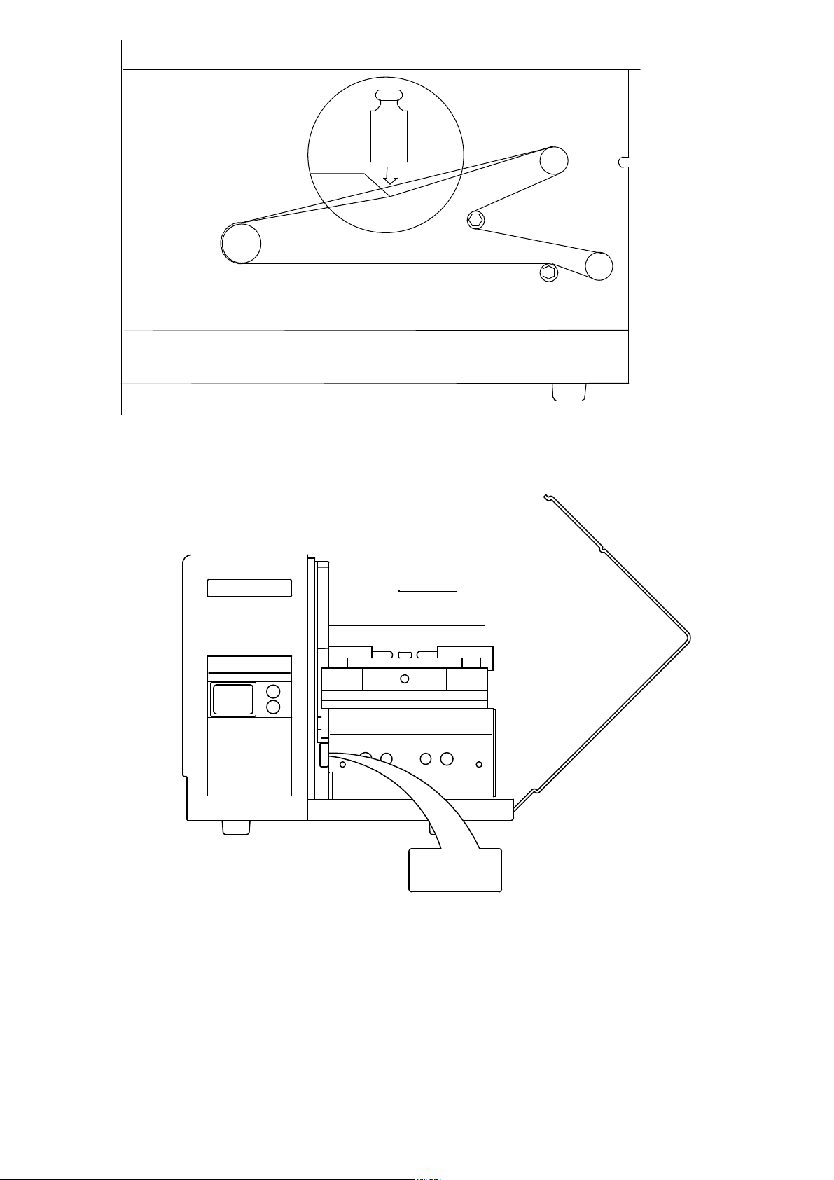
12.5. DRIVE BELT REPLACEMENT
(see picture 28 and 29)
Disassemble the electronic cabinet from the printer
chassis as shown in paragraph 14.1, remove the 2
screws #131, 133 and the safeguard plate #134, then
13. PICTURES
loosen the idler #16. Replace the belt and stretch it by
the idler till you get a deflection of 4 to 6 mm when
applying a force of 7 N.
PICTURE 7
S2000/280 10
Page 11
21 105
25b
25c
25a 33 45 32
10
PICTURE 8
105
21
25c
25b
33
25a
10
45
32
PICTURE 9
105
32
28 15
10
33
25a
28
21
25c
25b
PICTURE 10
S2000/280 11
45 15
Page 12
20
112
139140
PICTURE 11 PICTURE 13
41
15
PICTURE 16
PICTURE 18
S2000/280 12
Page 13
119
116
114 120
115 121
PICTURE 19
PICTURE 20
S2000/280 13
Page 14
Y1
Y2
Y3
Y4
Y5
Y6
Y7
Y8
Y9
Y10
Y11
Y12
Y13
Y14
Y15
Y16
Y17
Y18
Y19
Y20
Y21
Y22
Y23
Y24
Y25
Y26
Y27
Y28
Y29
Y30
smart 2000/280
smart 2000/280
smart 2000/280smart 2000/280
Cutter
Ribbon sensor
Push button, Leds
Motor
Label sensor
Label taken sensor
Serial port
Thermal head 8 dots
Power supply
PICTURE 21 CPU BOARD - layout
S2000/280 14
Page 15
37
138
129
18
26
130
37
128
PICTURE 27
130
25c
18
112
16
133
134
131
PICTURE 28
S2000/280 15
Page 16
4-6 mm
7N
PICTURE 29
14. PART LIST AND RELEVANT PICTURES
XXXXXX
Serial Nr.
S2000/280 16
Page 17

Spare parts list
(items are referred to following pictures)
ITEM
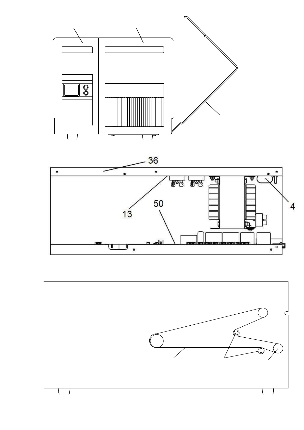
3 800944110 rear panel *
4 801292050 filter cap *
5 056102080 fuse 2A T *
6 056102020 fuse 1.6A T *
9 056102030 fuse 8A T *
10 801295040 label photosensor *
12 801665210 flat cable *
13 800944080 power board *
16 800925310 belt idler assembly *
18 800722460 nut *
19 061702070 bush *
20 800926290 peeling plate assembly *
21 801842380 feeding roller *
23 800742100 spring *
24 801872020 pinion *
25 800925890 print head lever *
26 800822011 thermal print head (8 dots) *
28 800762350 clip holder 4” *
29 800942690 ribbon rewinding assembly *
30 800942700 ribbon stock assembly *
31 801845083 side cover *
33 810940029 media position holder assembly *
35 80076212401 grey-green front cover *
36 801842083 electronic cabinet *
37 800542410 ribbon plate *
38 800782320 belt *
39 801622160 ribbon rewinding gear *
44 800925320 grey-green front cover (movable) *
48 801625030 ribbon photosensor *
49 800946610 stepping motor assembly *
50 800877000B6 CPU board *
51 800926320 heat dissipater assembly *
52 801842501 tie rod *
55 800925280 ring clip *
CODE
DESCRIPTION
smart
smart
smart smart
2000/280
2000/280
2000/2802000/280
S2000/280 17
Page 18
26
37
20
21
19
12
11
33 30 25 23 52 29 18 51
55
39
48 10 28
49
S2000/280 18
Page 19
4435
31
S2000/280 19
38
16
24
 Loading...