


Ceiling gas radiators
0694
n°
BL3197
- FORCED -
PS40
R2
PS60
R2
PS80
R2
PS90
R2
PS40
R2
PS60
R2
PS80
R2
PS90
R2
INSTRUCTION BOOKLET:
INSTALLATION AND
AFTER-SALES SERVICE
2
CONFORMITY
Our appliances are in conformity with:
Gas Directive 90/396/EEC
Electromagnetic Compatibility Directive 89/336/EEC
Low-Voltage Directive 73/23/EEC 0694
0694
RANGE
Poster 40
Poster 60
PS40R2 M0000
PS60R2 M0000
Poster 70
PS80R2 M0000
Poster 90
PS90R2 M0000
MODEL CODE

Dear Technician,
Congratulations on having chosen a POSTER PS CONVECTOR. This unit is able to provide many
years of well-being with extremely high standards of efficiency, reliability, quality and safety.
By means of this booklet, we intend providing you with all the information we consider necessary
for correct and easy installation.
Thank you once again
The Manufacturer
3
GARANZIA
The radiator comes with a specified warranty from the manufacturer. We invite
you to apply to the above-mentioned Technical service that with no payment will:
Make a free service on the convector
Ratify the warranty certificate furnished with apparatus that we like to advice
you to read.

GENERAL
General Information page 5
Fundamental safety rules 5
Description of the appliance 6
Safety devices 6
Identification 6
Structure 7
Technical details 8
Accessories 8
Functional wiring diagram 9
Control panel 10
INSTALLER
Receipt of product 11
- Pipe kit Ø 32 or Ø 54 mm with COMBINED end piece 11
- Pipe kit Ø 32 or Ø 54 mm SEPARATE end piece 13
Dimensions and weights 14
Installation area 14
Installation and masonry works 15
- CEILING installation with COMBINED end piece 17
- BRACKET installation with COMBINED end piece 20
- Fitting the CONVECTOR 22
- Installation with SEPARATE end pieces 23
- Fitting the stack 26
- Checking Pressure Loss (Pa) 26
Power connections 28
Gas supply connections 29
TECHNICAL AFTER-SALES SERVICE
Preliminary operations before initial startup 30
Initial startup 30
Control unit malfunctions 31
Controls during and after the initial startup 32
Switching from one type of gas to another 33
Settings 35
Routine maintenance 38
Removing and refitting the casing 45
Troubleshooting 46
This booklet consists of 48 pages.
- After removing the packaging, check the integrity and completeness of the
supply and in case of any discrepancies, contact the Agency that sold the
appliance.
4
CONTENTS
In same parts of the book there are used these symbols:
Attention: it used to underline particular caution or actions.
Prohibited: it used to underline the actions that don’t half to
be executed.
CONTENTS
-children and unassisted disabled persons must not
use the appliance.
- do not start electric appliances or equipment, such
as switches, household appliances etc in case of a
smell of fuel or of combustion fumes.
In this case:
o ventilate the premises by opening the doors and
windows;
o close the fuel opening/closing device;
o promptly call the After-Sales service or professionally qualified personnel.
-do not touch the appliance with wet or damp parts of
the body or if your feet are wet.
- do not close or reduce sizes of venting opening in
the installation area o on the appliance
- cleaning is forbidden without first disconnecting the
appliance from the power mains by turning the
master switch, if fitted, to "OFF" or taking out the
plug.
- It is forbidden to change or tamper with safety or
setting devices without prior manufacturer agreement
- do not pull, disconnect or twist the power cables
exiting from the appliance even when this is disconnected from the power mains. Do not place objects,
such as towels, rags, etc., on the appliance which
could cause malfunctions or prove to be a hazard
- Never leave packaging material (cartons, plastic
bags, etc.) within reach of children as this could be a
potential hazard source.
- After removing the packaging, check the integrity
and completeness of the supply and in case of any
discrepancies, contact the Agency that sold the
appliance.
- The appliance must be installed by companies
approved pursuant to Law no. 46 dated 5 March
1990. Upon completing the installation, such companies must issue a declaration of installation conformity in accordance with applicable national laws and
the instructions provided by the Manufacturer in the
installer's booklet attached to the product.
- The appliance must only be used for the purpose
intended by the Manufacturer and for which it has
been expressly designed. The Manufacturer
disclaims any contractual and non-contractual liability for injuries caused to people or animals and
damage to things, due to installation errors, wrong
settings, bad maintenance or improper use.
If the appliance is not used for a long period of time,
the following operations must be performed:
- position the master switch (if fitted) on "off" or
disconnect the plug from the power mains;
- close the gas tap.
Once in the year you must service the appliance.
- This booklet and that of the User are an integral
part of the appliance and must therefore be carefully
looked after and ALWAYS accompany the appliance
even when this is sold to another person or user or
transferred to another system. In case of damage or
loss, ask the Area After-Sales Service for another
copy.
5
GENERAL
GENERAL INFORMATION
FUNDAMENTAL SAFETY RULES
Please remember that the use of products involving fuels and electricity requires the enforcement of a number of
fundamental safety rules such as:
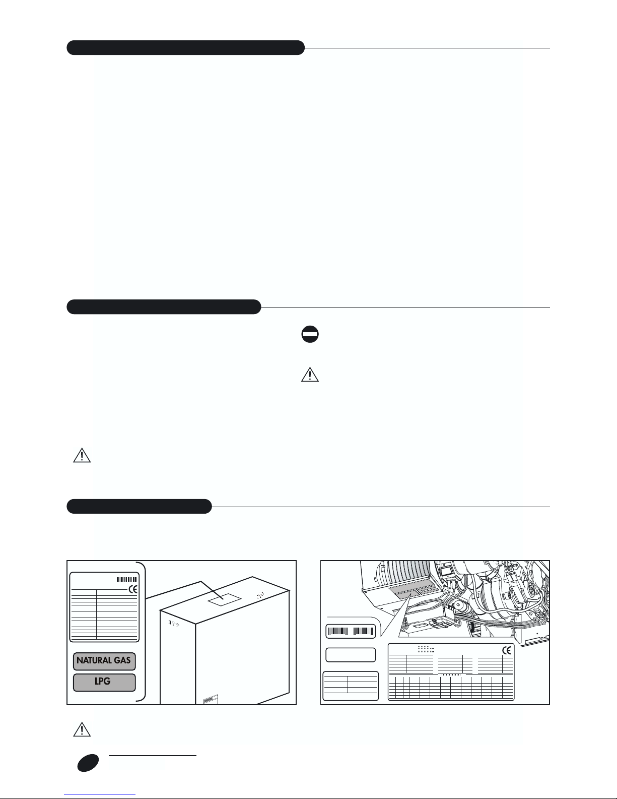
The appliance is identifiable by means of:
- the packaging label
- the Technical Plate
which shows the serial number, the model and the
main technical/performance data.
CONVECTOR units are independent gas appliances
for heating environments.
They use an atmospheric burner with combustion
chamber of the C TYPE, sealed with respect to the
place of installation, offering utmost safety as the
return is prevented of exhaust fumes or fuel into the
environment.
The combustion air is taken from outside the place of
installation and the combustion products are conveyed outside by means of the centrifugal fan fitted
to the appliance.
In view of their compact dimensions, the appliances
can be installed in small spaces.
The appliances are factory set for running on NATURAL GAS and can be transformed for LPG
(G30/G31) thanks to the nozzle kit provided as standard
.
The heat exchanger, consisting of aluminium die
casting with fins, ensures high combustion efficiency.
The tangential fan ensures rooms are quickly heated
up after switch-on.
An electronic board controls all the main appliance
functions and automatically interrupts the gas supply
in case of a fault.
The control panel permits starting or stopping the
appliance in "manual" mode and restoring normal
operation after a fault.
- The remote control permits programming weekly
operating periods, setting the temperature and starting summer ventilation.
6
GENERAL
TERMOCONVETTORE
TERMOCONVETTORE
DESCRIPTION OF THE APPLIANCE
The appliance features the following safety devices:
- Safety thermostat: this trips and switches the
appliance to stop mode if the temperature in the
exchanger exceeds the set limit (107°C).
- Pressure switch: this trips and switches the
appliance to safety standby in case of faults in the
fume extraction circuit.
- Protection fuse: this protects the electrical parts of
the appliance from any power surges.
The engagement of the safety devices points to a
potentially hazardous appliance malfunction; contact
the Manufacturer's After-Sales Service immediately.
The appliance must never ever be operated with the
safety devices not engaged or tampered with.
The safety devices must only be replaced by the
Manufacturer's After-Sales Service, using only original spare parts. Refer to the attached spare parts
catalogue.
To order spare parts and/or perform technical jobs,
the exact model of the appliance must be known.
After making the repairs, perform a start-up test and
check correct operation.
SAFETY DEVICES
IDENTIFICATION
Tampering with and removing the Technical Plate will make it impossible to identify the product with any certainty and
make any installation and maintenance job difficult.

7
GENERAL
1 Safety thermostat
2 Technical plate Gas Valve
3 Control unit
4 Protection fuse
5 Digital remote control
6 Main switch
7a "Integrated" room heat probe
7b "Split" room heat probe
8 Display
9 Battery holder (buffer batteries)
10 Condenser (mod. 70 and 90)
11 Convection fan
12 Power plug
13 Gas valve
14 Combustion fan
15 Room thermostat
16 Burner unit
17 Heat exchanger
16
14
15
13
3
4
5
6
1
2
7b
891011
17
12
7a
STRUCTURE

On request, the following accessories are available:
8
GENERAL
MODEL
II 2H3+
mbar
kW
kW
%
-
V~Hz
W
-
n°
Ø mm
mbar
m
3
/h
kg/h
kg/h
m
3
m3/h
kg
1
230 ~ 50
135
IP20
3
20
C13 / C33 / C53 / C63
80
G20
G30/G31
7,4 / 5,07
8 / 5,6
92,5 / 90,7
196
335
39,5
12 28,5/35,8
1,42 0,82
60
G20
G30/G31
5,85 / 4,0
6,5 / 4,55
90,2 / 88,4
155
265
32
12 28,8/36,7
1,30 0,74
40
G20
G30/G31
3,5 / 2,4
3,85 / 2,7
90,5 / 88,5
95
160
23,5
12 28,8/36,8
1,02 0,58
90
G20
G30/G31
9,1 / 6,2
10 / 7,0
91 / 83
245
410
47,5
10 27,2/34,5
1,65 0,95
0,407
0,285
0,688
0,481
0,847
0,593
1,06
0,742
0,303
0,212
0,512
0,358
0,630
0,441
0,788
0,552
G20
0,299
0,209
0,505
0,354
0,621
0,435
0,777
0,544
G30
G31
Fuel
Mains gas supply pressure (nominal) G20
Category of appliance
Type of appliance
Nom. heat output / min. HI
Nom. heat input /min. HI
Working efficiency Pn
Efficiency class*
Power supply
NOM power input
Insulation standard
Nozzles
Pressure at nozzles
Gas consumption (15°C) nom. / red
.
Quantity of heated air (approximate figure)
Gross weight (with packaging)
* Efficienc
y
class obtained according to prEN 1266 dated 6/1997.
MAX volume, room heated by a
convector (approximate figure)
Wall spacer bracket 30
DESCRIPTION CODE
Wall spacer bracket 50
90° curves _Ø 32mm pipe union
Extension Ø 32mm L = 500mm
Extension Ø 32mm L = 1000mm
Outer protection grille "GP" for separate end piece Ø 32mm
Griglia prot. esterna "GPu" per Term. Unico Ø 32mm
Stack for pipe Ø 32mm
90° curve _Ø 54mm pipe union
Extension Ø 54mm L = 500mm
Extension Ø 54mm L = 1000mm
90°__curve Ø 54mm cast
Outer protection grille "GP" for separate end piece Ø 54mm
Recessed screen "SDP" for separate end piece Ø 54mm
Stack for pipe Ø 54mm
Weekly TIMER
Wall spacer bracket 70
Wall spacer bracket 90
Daily TIMER
INSULATION for pipe Ø 54mm L = 1000mm (pack of 4 pcs.)
INSULATION for pipe Ø 32mm L = 1000mm (pack of 5 pcs.)
Inlet/Outlet end piece Ø 54mm L = 6 cm
Inlet/Outlet end piece Ø 32mm L = 5 cm
135° curves _Ø 54mm
135° curves _Ø 32mm
Recessed screen "SDP" for separate end piece Ø 32mm
Outer protection grille "GPu" for combined end piece Ø 54mm
70000666 00
70000676 00
70000700 00
70000720 00
70000710 00
70000350 00
70000600 00
70000730 00
70000370 00
70000390 00
70000380 00
70000755 00
70000350 00
70000365 00
70000740 00
70000280 00
70000686 00
70000696 00
70000270 00
70000850 00
70000840
70000465 00
70000466
70000375 00
70000705 00
70000365 00
70000610 00
TECHNICAL SPECIFICATIONS
ACCESSORIES

9
GENERAL
TA
T1
CN1
3 2 1
CN2
1 2
CN6
3 2 1
CN3
4 3 2 1
VC
S I T
7530108_0B
CN9
1 2 3 4 5 6
CN7
1 2
CN8
1 2 3
CN5
1 2 3 4
1
2
EV2
4
3
TX
+
RX
PP
SAS
SE
PS
F 2AL 250V
TL
LN
CL
230V~
EV1
SAI
CR
DDS 174
General wiring diagram
PS-R2
CVT
V.T.
BL
RD
WH
PP BATTERY HOLDER
SIT CONTROL BOARD
EA IGNITION ELECTRODE
ER DETECTION ELECTRODE
EV1 ELECTRIC GAS VALVE
F FUSE
CL LINE CONNECTOR
EV2 POWER MODULATOR
L PHASE LINE
N NEUTRAL LINE
CRD DIGITAL REMOTE CONTROL
PS PRESSURE SWITCH
TL LIMIT THERMOST AT
SA I INTEGRATED ROOM PROBE
SAS SPLIT ROOM PROBE
SE OUTSIDE PROBE (optional)
VC COMBUSTION FAN
VT TANGENTIAL FAN
CN... CONNECTOR
T1 POWER TERMINAL
VT TANGENTIAL FAN
TA IGNITION TRANSFORMER
GND/+24V REMOTE POWER SUPPLY
TX/RX TRANSMISSION/SIGNAL RETURN
BL BLUE WIRE
WH WHITE WIRE
RD RED WIRE
ER
WIRING DIAGRAM

12345
DESCRIPTION OF KEYS
a - Switch on the appliance (key 3);
b - Press MENU key (key 5);
c - Press DOWN key (key 2) to move the cursor onto the required menu
line;
d - Press SELECT key (key 5);
note: keys 1, 2, 4 and 5 acquire different functions in the different
menus.
• required setting
e - Press keys 1 and 2 to set the required parameter;
f - Press key 4 to store the parameter just set and pass onto the next;
g - Press OK key (key 5) to store all the set parameters and return to
main menu;
10
GENERAL
CONTROL PANEL
 Loading...