


Mod. 12 kW
Mod. 12 kW E.P.
0476
BR0969
USA - USER MANUAL AND ASSEMBLY INSTRUCTIONS

1
1
16
14
2
3
4
5
6
7
8
9
9
1313
10
11
1212
1515
1
2
3
4
5
7
11
Fig.3
KEY: 1) fastening knob, 2) cover dish, 3) exchanger head, 4) protection grid, 5) glass pipe, 6) magnet, 7) burner, 8) ignition/adjustment knob, 9) battery holder, 10) control unit (remote control Mod.), 11) tank support
base, 12) side panel, 13) control cover panel, 14) trolley, 15) Antiwind, 16) SMALL remote control (remote
control Mod.).
ZEICHENERKLÄRUNG: 1) Befestigungsknopf, 2) Abdeckungsschirm 3) Wärmeaustauscherkopf, 4) Schutzgitter, 5)
G
lasrohr, 6) magnet, 7) Brenner, 8) Einschalt-/Einstellknopf, 9) Batteriefach, 10) Steuereinheit (Mod. Mit
Fernbedienung), 11) Gasflaschenstützfläche, 12) seitliche Verkleidungstafel, 13) Verkleidungstafel der
Bedienelemente, 14) Schlitten, 15) Gegen wind, 16) klein Fernbedienung (Mod. Fernbedienung).
LEGENDE:
1) de vaststelling van de knop, 2) te dekken schotel, 3) het hoofd warmtewisselaar, 4) de bescherming van grid, 5) glazen buis, 6) magneet bevestiging, 7) brander, 8) knop ontsteking / controle, 9) batterijhouder, 10) controle-eenheid (Mod afstandsbediening), 11) tank draagvlak, 12) zijpaneel, 13e) deksel van
het bedieningspaneel, 14) trolley (optioneel) 15) Wind, 16) Mini Remote Control (Remote-modus).
LÉGENDE:
1) la fixation bouton, 2) couvrir le plat, 3) l'échangeur de la tête, 4) grille de protection, 5) tube de
verre, 6) de fixation magnétique, 7) du brûleur, 8) d'allumage / bouton de commande, 9) boî tier de la batterie, 10) unité de contrôle (Mod télécommande), 11) de base support du réservoir, 12) 13 du panneau latéral)
couvercle du panneau de contrôle, 14) du chariot 15) Vent, 16) Mini Remote Control (mode distant).
2
TOOLS recommended for fitting and/or maintenance (not supplied by the Manufacturer): 1) brush for cleaning the glass pipe, 2)
cross-headed tip screwdriver, 3) LPG pressure regulator, 4) 19 fixed wrench for regulator, 5) 8 fixed wrench, 6) scratchproof soft cloth for outside cleaning, 7) protection gloves for transport, 8) compressed air for inside cleaning.
Empfohlene WERKZEUGE für Montage und Wartung (nicht vom Hersteller geliefert): 1) Bürste zum Reinigen des Glasrohrs, 2)
Kreuzschraubenzieher, 3) LPG-Druckregler; 4) 19-Maulschlüssel für den Regler; 5) 8,6-Maulschlüssel; 6) weiches, nicht
scheuerndes Tuch zur externen Reinigung; 7) Schutzhandschuhe für den Transport; 8) Druckluft zur internen Reinigung.
1 2 3 4
5 6 7 8
Aria compressa
Compressed air
nr.
19
nr.
8

Fig.1
Fig.2
3
1
3
2
1
1,5Volt
torcia
KD
D
AM1
R14
1,5Volt
stilo
KAA
AA
AM3
1,5Volt
ministilo
K3A
AAA
AM4
2
3
Fig.4
1
2
3
4
Fig.6
1
4
3
2
Fig.5
4
4
5
7
10
11
9
12
2
1
11
8
Fig.7
1
1
2
10
11
9
5
13
7
12
14
15
16
1
4
Fig.8
1
2
3
5
6
7
8
4
Fig.9
5
Fig.10
1
2
2
Fig.11
Fig.12
6
2 31
optional
Fig.14
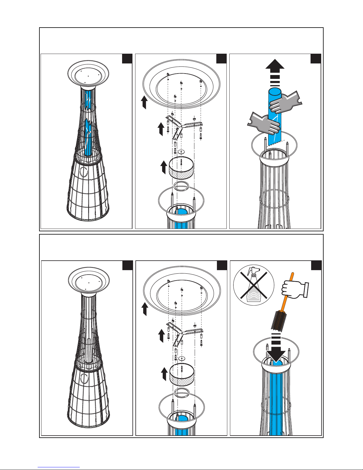
UK - TUBE MAINTENANCE
DE - WARTUNG TUBE
FRA - TUBE EN VERRE PROPRE
NL - SCHONE GLAZEN BUIS
2 31
F
ig.13
UK - REPLACING PIPE
D
E - ERSATZ TUBE
FRA - TUBE DE VERRE DE RECHANGE
N
L - VERVANGING GLAZEN BUIS
7
centralina/control unit
telecomando/remote control
burner Off
Off
MIN
MED
On MAX
Fig.15
Fig.16
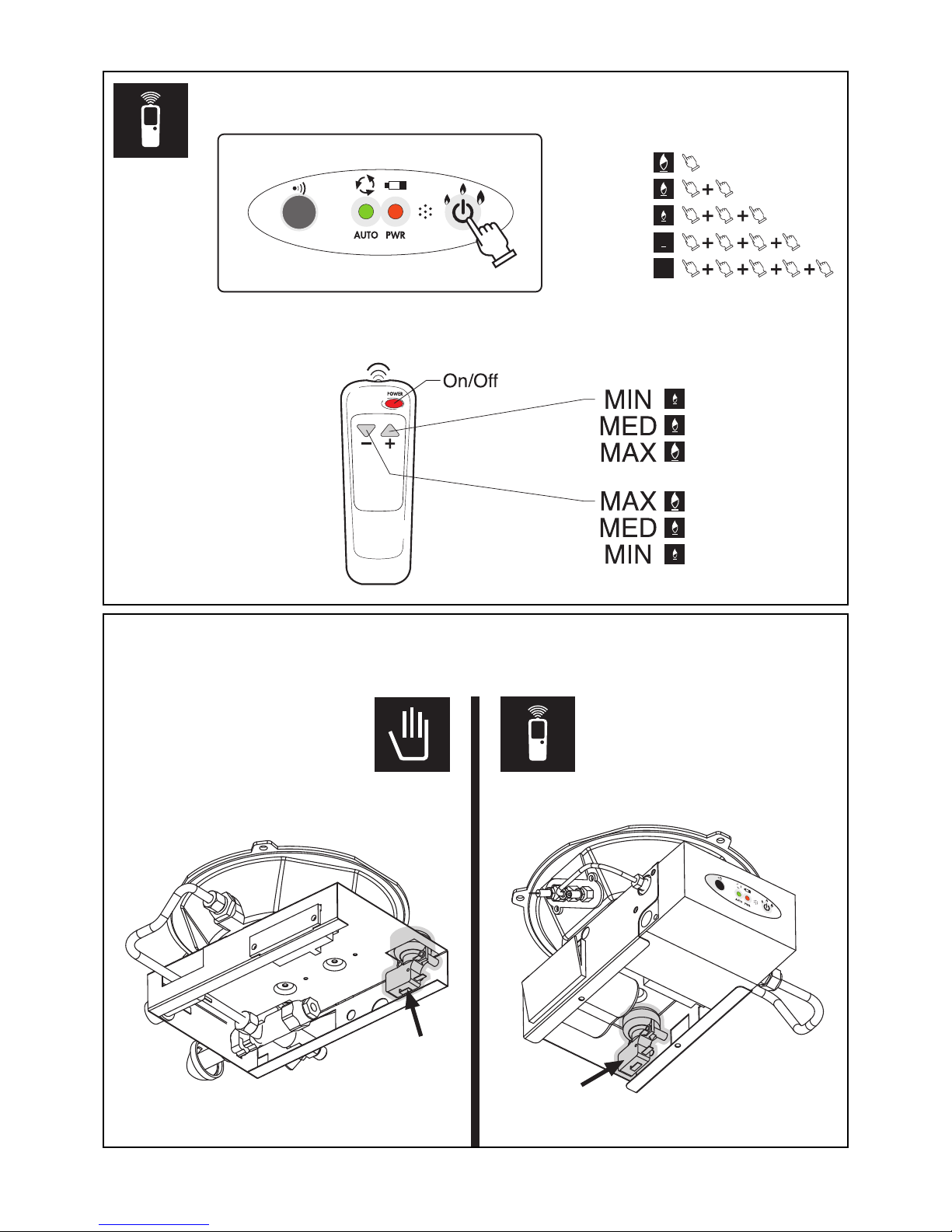
UK - DUNP-SWITCH SAFETY DEVICE
DE - SAFETY DEVICE ANTI-KIPPEN
FRA - ROULETTES ANTI-BASCULE
NL - ANTITIPPER
8

1
1
2
2 3
4 5 6
7 8 9
10 11 12
2
2
2
2
2
2
2
2
2
1
1
1
1
F
ig.17
UK - TANK FIXING
D
E - TANK HALTEBAND
FRA - SERRURE A CYLINDRE
N
L - SLOTCILINDER
8a

NO
4
5
6
7
6
4
5
7
7
5
5
5
8b
UK - With kit lights installed, the appliance must be covered and protected from the rain.
D
E - Bei Montage mit LED, müssen diese vor Regen geschützt werden.
FRA - Avec le kit installé feux, placer l'appareil dans un endroit couvert et protégé de la pluie.
N
L - Met de kit geïnstalleerd lichten, plaatst u het apparaat in een afgedekt en beschermd tegen regen.
F
ig.18

8c
UK - KIT lights, battery and charger.
Please read the information wrapping the charger and the instructions .
-
Do not use the charger in areas not covered or outside.
- The battery (min 10 hours) is complete only when the green LED on the charger turns off.
- Do not use the battery for more than 10 hours operation, this device requires a level Minimum charge for its proper operation and maintenance (about 200 charge cycles).
- Do not connect directly the battery charger to LED circuit to prevent damage.
DE - KIT Beleuchtung, Batterie und Ladegerät.
Bitte lesen Sie die Informationen Wickeln Sie das Ladegerät und das Merkblatt die darin enthaltenen für die korrekte Verwendung von dieses Kit.
- Verwenden Sie nicht das Ladegerät in Bereichen, die nicht abgedeckt oder außen.
-
Die Batterie (min 10 Stunden) ist nur vollständig, wenn die grüne LED am Ladegerät erlischt.
- Verwenden Sie nicht die Batterie für mehr als 10 Stunden Betrieb, benötigt dieses Gerät eine Ebene
Mindestgebühr für den ordnungsgemäßen Betrieb in Zeit (ca. 200 Ladezyklen).
- Nicht direkt mit dem Akku-Ladegerät LED-Schaltung, um Schäden zu verhindern.
NL - KIT verlichting, accu en lader.
Lees de informatie wikkelen van de lader en het instructieblad vervat in het voor het juiste gebruik van deze kit.
- Gebruik de lader niet in gebieden die niet of bedekt de buitenkant.
- De accu (min 10 uur) is pas compleet als het groene lampje op de lader wordt uitgeschakeld.
- Gebruik de batterij niet gebruiken voor meer dan 10 uur bediening, moet dit apparaat kunnen een niveau
minimum tarief voor de goede werking ervan in tijd (ongeveer 200 laadcycli).
- Niet direct aansluiten op de accu lader LED circuit om schade te voorkomen.
FRA - Feux de KIT, batterie et chargeur.
S'il vous plaît lire les informations enveloppant le chargeur et la feuille d'instructions qu'il contient pour l'utilisation
correcte des ce kit.
- Ne pas utiliser le chargeur dans les zones non couvertes ou l'extérieur.
- La batterie (min 10 heures) est complète seulement lorsque le voyant vert sur le chargeur s'éteint.
- Ne pas utiliser la batterie pendant plus de 10 heures fonctionnement, ce dispositif nécessite un niveau Tarif minimum pour son bon fonctionnement dans les temps (environ 200 cycles de charge).
- Ne pas se connecter directement au chargeur de batterie circuit LED pour éviter tout dommage.
UK - MOUNTING APPARATUS (Fig. 19)
The device has been designed and comes in two pieces to facilitate both storage by the user that the shipment.
The extraction from the packaging and the subsequent assembly operation is very simple, just one person.
DE - Montage-Vorrichtung (Abb. 19)
Das Gerät wurde so konzipiert und kommt in zwei Stücke, sowohl Lagerung durch den Benutzer, dass die
Sendung zu erleichtern. Die Extraktion aus der Verpackung und der anschließenden Montage Bedienung ist sehr
einfach, nur eine Person.
NL - MONTAGE APPARAAT (Fig. 19)
Het apparaat is ontworpen en wordt geleverd in twee stukken om zowel opslag door de gebruiker die de verzending te vergemakkelijken. De extractie van de verpakking en de daaropvolgende assemblage is zeer eenvoudig,
maar een persoon.
FRA - Dispositif de montage (Fig. 19)
Le dispositif a été conçu et est disponible en deux morceaux pour faciliter le stockage par l'utilisateur que l'expédition. L'extraction de l'emballage et de l'opération de montage ultérieur est très simple, une seule personne.

8d
Fig.20
F
ig.19
UK - ASSEMBLY EQUIPMENT
DE - MONTIEREN SIE DEN APPARAT
FRA - MONTER LES APPAREILS
NL - MONTEER HET APPARAAT
UK - ASSEMBLY COFFEE TABLE (Ø 80cm)
DE - AUFSPANNFLACHE (Ø 80cm)
FRA - ASSEMBLEZ LA TABLE (Ø 80cm)
NL - MONTAGETAFEL (Ø 80cm)

8e
1
1
2
3
Fig.21
Lightfire Dolce Vita SEEBECK

UK - Lightfire "Dolce Vita" with the SEEBECK effect
IMPORTANT! This device requires no external power supply (mains or extra rechargeable battery).
This model is equipped with a heat exchanger (1) in aluminum that, thanks to the effect thermoelectric Seebeck, converts the
h
eat of the flame into electricity which is then used to power both the KIT LED lights that the gas valve.
- KIT LED Lights (supplied): can be switched on or off at will, their use is only possible after a minimum time of continuous
operation of the unit.
- Gas valve: is powered by the batteries during the first ignition and for the first 5 minutes of operation. Once you get past the
f
irst 5 minutes of continuous operation, the system enters Seebeck at full capacity feeding the gas valve and excluding the bat-
teries automatically. The saving of battery usage, during operation, allows an extension of their duration in time.
IMPORTANT! In the case in which the heat exchanger (1) is soiled in a way accidental (liquid, powder , etc.), Its operation is not compromised. For its possible cleaning by the user, you must: DO NOT REMOVE the heat exchanger from
i
ts housing, allow the appliance to cool down completely, use neutral products and a lint fiber residues.
IMPORTANT! The dismantling of the heat exchanger must be carried out by authorized personnel, who once finished
the surgery, will have to replace all the pressure screws (2) of the thermoelectric module (3) in their original position
and at the correct pressure so as to restore the operation of the system.
IMPORTANT! You will not modify the equipment in each of its components and tamper with the system gas or electric,
any changes decreed the immediate cessation of Warranty and may cause damage to persons or things of which the
Supplier is not liable.
D
E - Lightfire "Dolce Vita" met de Seebeck effect
BELANGRIJK! Dit apparaat vereist geen externe voeding (netvoeding of een extra oplaadbare batterij).
Dit model is uitgerust met een warmtewisselaar (1) in aluminium dat , dankzij het effect thermo Seebeck, zet de hitte van de
vlam in elektriciteit die vervolgens wordt gebruikt om de macht zowel het KIT LED-lampjes die de gasklep .
- KIT LED verlichting (meegeleverd): kan worden in-of uitgeschakeld kan worden, het gebruik ervan is alleen mogelijk na een
minimum periode van continue werking van het apparaat .
- Gasklep: wordt gevoed door de batterij tijdens het eerste contact en de eerste 5 minuten bedrijf . Als je eenmaal voorbij de
eerste 5 minuten van continue werking , gaat het systeem Seebeck op volle capaciteit voeden van de gasklep en automatisch
exclusief de batterijen. De besparing van het gebruik van batterijen , terwijl de bediening van de apparatuur , kan een verlenging van de duur in de tijd.
BELANGRIJK ! In het geval waarin de warmtewisselaar (1) is vervuild op een manier toevallige (vloeistof, poeder, enz.
.), Is De werking ervan niet in het gedrang . Voor zijn mogelijk schoonmaken door de gebruiker, moet u: NOOIT de
warmtewisselaar niet uit zijn behuizing , laat het apparaat volledig afkoelen , gebruik neutrale producten en een lint
vezel residuen.
BELANGRIJK ! De ontmanteling van de warmtewisselaar moeten door bevoegd personeel , die eens klaar met de operatie worden uitgevoerd , moeten alle druk schroeven (2) van de thermo-elektrische module (3) te vervangen in hun oorspronkelijke positie en op de juiste spanning om zo het herstel van de werking van het systeem.
BELANGRIJK ! je zal niet de apparatuur te wijzigen in elk van zijn componenten en knoeien met het systeem gas-of
elektrische wijzigingen verordende de onmiddellijke beëindiging van de garantie en kan schade aan personen of zaken
waarvoor de fabrikant niet aansprakelijk kan veroorzaken.
FRA - Lightfire "Dolce Vita" avec l'effet Seebeck
IMPORTANT! Cet appareil ne nécessite aucune alimentation externe (secteur ou batterie rechargeable supplémentaire).
Ce modèle est équipé d'un échangeur de chaleur (1) en aluminium qui, grâce à l'effet thermoélectrique Seebeck, convertit la
chaleur de la flamme en électricité qui est ensuite utilisé pour alimenter à la fois le KIT LED lumières que la vanne de gaz.
- KIT lumières LED (fournies): peuvent être activés ou désactivés à volonté, leur utilisation n'est possible qu'après un délai
minimum de fonctionnement continu de l'appareil.
- Vanne de gaz: est alimenté par des batteries au cours du premier allumage et pendant les 5 premières minutes de fonctionnement. Une fois que vous avez passé les 5 premières minutes de fonctionnement continu, le système entre Seebeck à pleine
capacité alimentant le robinet de gaz et excluant automatiquement les batteries. L'économie d' utilisation de la batterie pendant
le fonctionnement, permet une extension de leur durée dans le temps.
IMPORTANT! Dans le cas où l'échangeur de chaleur (1) est souillé d'une manière accidentelle (liquide , poudre, etc.),
Son fonctionnement ne soit pas compromise . Pour sa possible nettoyage par l'utilisateur, vous devez: Ne retirez pas
l'échangeur de chaleur de son logement, laissez l'appareil se refroidir complètement, utiliser des produits neutres et
un résidu de fibre de fibre.
IMPORTANT! Le démantèlement de l'échangeur de chaleur doivent être effectués par du personnel autorisé, qui une
fois terminé l'opération, devra remplacer toutes les vis de pression (2) du module thermoélectrique (3) dans leur position d'origine et à la bonne pression afin de rétablir la le fonctionnement du système .
IMPORTANT! vous ne pourrez pas modifier l'équipement dans chacune de ses composantes et de trafiquer avec le gaz
de réseau ou électrique, les modifications décrétées la cessation immédiate de la garantie et peut causer des dommages aux personnes ou aux biens dont le fournisseur n'est pas responsable.
8f

8g
nero / black
rosso / red
nero / black
grigio / grey
grigio / grey
nero / black
marrone / brown
marrone / brown
bianco / white
marrone / brown
marrone / brown
bianco / white
rosso
red
nero
black
rosso
red
nero
black
VALVOLA GAS
GAS VALVE
BATTERIE
BATTERY
MODULI TERMICI
THERMAL MODULE
SCHEDA ELETTRONICA
ELECTRONIC BOARD
LUCI LED
LED LIGHTS
DolceVita E.P. - serie 2

8h
Tab. 1
A B C D E F G H
kWIkWLlb/h
M
Ø “
N
Ø “
O
G30
inch water
Q
LEGENDA colonne: - Columnes esplication
A....Q: sigla paese - land identification - désignation du pays - landesbezeichnung - indicação do país - land van bestemming - määrämaa - bestemmelsesland - bestemmelsesland - pais de destino
B: serie apparecchio - appliance serial- série de l’appareil- s erie des geräts - série aparelho - serie aparato - merk - merkki - merke - mærke - marka
C
: modello apparecchio - appliance model - serie aparato - modell des geräts -modelo aparelho - modelo aparato - model - mall - model - modelo
D: categoria gas - gas categories - type de gaz - gaskategorie - categoria de gás - categoría de gas - gascategorie - kaasukateg oria - gasskategori - gaskategori - categoria de gás
E: tipo apparecchio - appliance type - type d’appareil - t yp des geräts - tipo do aparelho - versión aparato - t oesteltype - laitetyyppi - type apparat - type apparat - tipo de aparelho
F: matricola apparecchio - appliance code - code appareil - kode geräts - código aparelho - aparato código - serienummer - sarja numero - serienummer - serienummer - número de série
G: numero codice pin - nip number - numéro de code pin - pin-kod enummer - número de código pin - número de codificación pin - pi n code - pin-koodi - pin-kode - pin-kode - código pin
H: portata termica nominale - nominal heat input - débit calorif ique nominal - nennbelastung - carga nominal - carga nomina - nominale belasting - nimelliskuormitus - nominell belastning - nominel belastning - carga nominal
I: portata termica ridotta - reduced heat input - débit calorifi que minimal - mindestbelastung - carga mínima - carga mínima - minimum belasting - vähimmäiskuormitus - minimumsbelastning - mi nimumsbelastning - carga mínima
L: consumo orario gas - gas consuction - consommation de gaz - gasverbrauch - consumo de gás - consumo de gas - consumptie - kul utus - forbruk - forbrug - consumo
M: diametro ugello - injector diameter - diamètre du gicleur - durchmesser einspritzdüse - diâmetro do injector - diámetro inye ctor - diameter inspuiter - ruiskeen läpimitta - diameter innspr øyter - diameter indsprøjter - diâmetro do injector
N: diametro diaframma - diafragme diameter - diamètre du diaphra gme -é durchmesser blende - diâmetro do diafragma - diámetro dia fragma - diameter diafragma - välikalvon läpimitta - diameter di afragma - diameter diafragma - diâmetro do diafragma
O: press. alim. BUTANO G30 - inlet gas pressure BUTANE G30 - pression de gaz entrante BUTANE G30 - Eintrittsgasdruck Butan G30 - pressão do gás de entrad a BUTANO G30 -
presión gas entrante BUT ANO G30 - Gasdruk inlaat Butaan G30 - Butaani G30:n syötön kaasu paine - Gasstrykk inntak butan G30 - Gastryk indtag butan G30 - Pressã o de gás à entrada Butano G30
P: press. alim. PROPANO G31 - inlet gas pressure PROPANE G31 - pression de gaz entrante PROPANE G31 - Eintrittsgasdruck Propan G31 - pressão do gás de entra da - PROPANO G31
presión gas entrante PROP ANO G31 - Gasdruk inlaat Propaan G31 - Propaani G31:n syötön kaa supaine - Gasstrykk inntak propan G31 - Gastryk indtag propan G31 - Pressão de gás à entrada Propano G31
-
USA
0694
-
G30:
1
,922
G31:
1,892
A
1
-
Lightfire Dolce V
ita
remote PERFORMANT
SUN FOX
P
G31
inch water
AT= Osterraich, BE= Belgique, DE= Deutchland, ES= Espana, IT= Italia, DK= Denmark, FI= Finland, GR=
Greece, IS= Iceland, LU= Luxembourg, NL= Holland, NO= Norska, PT= Portugal, SE= Sverige, CZ=Cesko,
EE=Eesti Vab., HU= Magyar Köz, L T=Latui¡as Rep., L V-Lietuvos Resp., PL=Polska Rze., MT=Malta, RO=România,
SK=Slovensko, SI=Slovenija, TR=Türki¡e, BG=Bulgaria, CY=Cyprus.
SI, YES, JA, OUI
, DA, ANO
NO, NEEN, NEIN, NON
, NE
1
1,0
1
1,0
L
.P
.G.
-
USA
41380 B
tu
-
1
2,0
(H
s)
17930 B
tu - 5,2
(H
s)
Tab. 2
A B C D E F G H
kWIkWLgal/h
M
Ø “
N
Ø “
O
G20
inch water
Q
LEGENDA colonne: - Columnes esplication
A....Q: sigla paese - land identification - désignation du pays - landesbezeichnung - indicação do país - land van bestemming - määrämaa - bestemmelsesland - bestemmelsesland - pais de destino
B: serie apparecchio - appliance serial- série de l’appareil- s erie des geräts - série aparelho - serie aparato - merk - merkki - merke - mærke - marka
C: modello apparecchio - appliance model - serie aparato - modell des geräts -modelo aparelho - modelo aparato - model - mall - model - modelo
D: categoria gas - gas categories - type de gaz - gaskategorie - categoria de gás - categoría de gas - gascategorie - kaasukateg oria - gasskategori - gaskategori - categoria de gás
E: tipo apparecchio - appliance type - type d’appareil - t yp des geräts - tipo do aparelho - versión aparato - t oesteltype - laitetyyppi - type apparat - type apparat - tipo de aparelho
F: matricola apparecchio - appliance code - code appareil - kode geräts - código aparelho - aparato código - serienummer - sarja numero - serienummer - serienummer - número de série
G: numero codice pin - nip number - numéro de code pin - pin-kod enummer - número de código pin - número de codificación pin - pi n code - pin-koodi - pin-kode - pin-kode - código pin
H: portata termica nominale - nominal heat input - débit calorif ique nominal - nennbelastung - carga nominal - carga nomina - nominale belasting - nimelliskuormitus - nominell belastning - nominel belastning - carga nominal
I: portata termica ridotta - reduced heat input - débit calorifi que minimal - mindestbelastung - carga mínima - carga mínima - minimum belasting - vähimmäiskuormitus - minimumsbelastning - mi nimumsbelastning - carga mínima
L: consumo orario gas - gas consuction - consommation de gaz - gasverbrauch - consumo de gás - consumo de gas - consumptie - kul utus - forbruk - forbrug - consumo
M: diametro ugello - injector diameter - diamètre du gicleur - durchmesser einspritzdüse - diâmetro do injector - diámetro inye ctor - diameter inspuiter - ruiskeen läpimitta - diameter innspr øyter - diameter indsprøjter - diâmetro do injector
N: diametro diaframma - diafragme diameter - diamètre du diaphra gme -é durchmesser blende - diâmetro do diafragma - diámetro dia fragma - diameter diafragma - välikalvon läpimitta - diameter di afragma - diameter diafragma - diâmetro do diafragma
O: press. alim. BUTANO G30 - inlet gas pressure BUTANE G30 - pression de gaz entrante BUTANE G30 - Eintrittsgasdruck Butan G30 - pressão do gás de entrad a BUTANO G30 presión gas entrante BUT ANO G30 - Gasdruk inlaat Butaan G30 - Butaani G30:n syötön kaasu paine - Gasstrykk inntak butan G30 - Gastryk indtag butan G30 - Pressã o de gás à entrada Butano G30
P: press. alim. PROPANO G31 - inlet gas pressure PROPANE G31 - pression de gaz entrante PROPANE G31 - Eintrittsgasdruck Propan G31 - pressão do gás de entra da - PROPANO G31
presión gas entrante PROP ANO G31 - Gasdruk inlaat Propaan G31 - Propaani G31:n syötön kaa supaine - Gasstrykk inntak propan G31 - Gastryk indtag propan G31 - Pressão de gás à entrada Propano G31
-
USA
0694
-
41380 B
tu
-
1
2,0
(H
s)
3
00 gal/h
A
1
-
Lightfire Dolce V
ita
remote PERFORMANT
17930 B
tu - 5,2
(H
s)
SUN FOX
P
-
inch water
AT= Osterraich, BE= Belgique, DE= Deutchland, ES= Espana, IT= Italia, DK= Denmark, FI= Finland, GR=
Greece, IS= Iceland, LU= Luxembourg, NL= Holland, NO= Norska, PT= Portugal, SE= Sverige, CZ=Cesko,
EE=Eesti Vab., HU= Magyar Köz, L T=Latui¡as Rep., L V-Lietuvos Resp., PL=Polska Rze., MT=Malta, RO=România,
SK=Slovensko, SI=Slovenija, TR=Türki¡e, BG=Bulgaria, CY=Cyprus.
SI, YES, JA, OUI
, DA, ANO
NO, NEEN, NEIN, NON
, NE
3,5
-
N
atural Gas
-
USA

- UK -
Contents
THE REMOTE CONTROL
GENERAL DESCRIPTION
ASSEMBLY
START-UP
SWITCH-OFF
MAINTENANCE
STORAGE
WARRANTY
TROUBLESHOOTING
9

CAREFULLY LOOK AFTER THIS BOOKLET FOR THE ENTIRE LIFE OF THE APPLIANCE
AND REQUEST A NEW ONE IN CASE OF DAMAGE OR LOSS!
IMPORTANT! SHOULD THE PARTS BE DAMAGED, DO NOT GO AHEAD WITH ASSEMBLY!
IMPORTANT! This appliance must be installed in compliance with the Regulations, Laws and
Standards applicable in the Country of use. Installation and use must be in conformity with
the instructions provided by the Manufacturer. Refer to the instructions before installing and
using the appliance.
IMPORTANT! ALL the maintenance, repair or modification operations MUST be performed
by professionally qualified and certified personnel and always using the Manufacturer’s
original spare parts.
IMPORTANT! This gas-fuelled appliance is a heat generator intended only for the use for which
it was designed and certified (with room temperature NOT below 0°C for Remote-controlled
mod.), or as an appliance for heating open, ventilated or outdoor environments. All other
uses are to be deemed improper and therefore hazardous. The Manufacturer disclaims all
liability for any injury to persons or animals or damage to things caused by improper use.
IMPORTANT! OPERATION IN CLOSED ENVIRONMENTS IS FORBIDDEN: OFFICES, INSIDE HOMES, STABLES, ANIMAL FARMS, PLACES NEAR GAS VAPOURS OR POTENTIALLY INFLAMMABLE DUSTS AND/OR EXPLOSIVES, ETC.
IMPORTANT! Carefully follow ALL the instructions and precautions indicated in this
booklet (concerning INSTALLATION, USE and MAINTENANCE). Failure to abide by these
instructions could cause malfunctions and or endanger people, animal and things.
IMPORTANT! THIS APPLIANCE IS GAS FUELLED AND PARTS OF IT BECOME HEATED.
CONSEQUENTLY, KEEP IT OUT OF REACH OF CHILDREN.
IMPORTANT! NEVER move the appliance with the burner still operating.
IMPORTANT! ALWAYS COMPLY WITH SAFETY DISTANCES FROM OBJECTS OR
INFLAMMABLE MATERIALS(Fig. 2).
IMPORTANT! TO ASSEMBLE AND USE, ABIDE BY THE FIRE-FIGHTING AND ACCIDENTPREVENTION REGULATIONS OF THE COUNTRY WHERE THE APPLIANCE IS USED.
IMPORTANT! DO NOT use the appliance set for LPG in basements or cellars.
IMPORTANT! The appliance made to use LPG, CANNOT be fed with or modified to use
natural gas and vice versa.
IMPORTANT! MODIFYING the appliance is absolutely forbidden except ONLY in those cases
indicated and authorised by the Manufacturer.
IMPORTANT! Fit the gas pressure regulator on the cylinder (fixed-setting type) in conformity with the TECHNICAL DATA and GAS SETTING plates on the appliance (Tab. 1 or 2).
IMPORTANT! Every time the cylinder is changed and periodically, using soapy water or
equivalent, make sure there are NO gas leaks from the pipes, from the cylinder connections, gas distribution connections and gas connection with the appliance. Replace the
seal every time the cylinder is changed and periodically check the state of wear, efficiency,
tube expiry data and all the connections.
IMPORTANT! Before making the connection, make sure the hose connector provided is in
conformity with the Regulations applicable in the Country of use.
IMPORTANT! Before proceeding with assembly operations, make sure all the parts making up
the appliance are suitable for the type of gas and pressures according to the Regulations applicable in the Country of use.
10

11
GENERAL DESCRIPTION
Due to its specific type of operation with direct and reflected irradiance, this appliance approximately heat up a surface of 13 m
2
with a range of action of 2 meters. The weather of your specific region could influence the device efficiency, as the appliance position (totally or in part
open space) as your subjective heating feelings. The heating feeling substaintially increases
close to the appliance.
The appliance is very simple to use and built according to CE safety standards. It has been
tested, approved and controlled by the Notified Approval Institute to which the Manufacturer has
always entrusted most of its certifications in the gas industry.
Types of installation:
- MOBILE, with the base free of restraints using the trolley (optional), with LPG fuel only (tank).
- FIXED, with the base fastened to the floor (this type of installation must be carried out only by
professionally skilled personnel), using Propane/Butane gas (large tank) or natural mains gas.
ASSEMBLY
Take all the parts making up the appliance out of the packaging, with special care given to the
burner unit (Fig. 3).
Check the integrity and the conformity of the contents of the packaging (the latter must be
disposed of according to applicable regulations):
A - Mod. with manual controls
- Appliance with carrying structure and special-glass pipe;
- Hose connection (make sure this complies with applicable regulations);
- Cover dish;
- Multilingual instruction booklet;
- Warranty Certificate.
B - Mod. with Remote Control
- Appliance with carrying structure and special-glass pipe;
- Hose connection (make sure this complies with applicable regulations);
- Cover dish;
- Multilingual instruction booklet;
- Warranty Certificate.
IMPORTANT! Always wear individual hand protection gear during appliance assembly and
positioning. Use the special accessory for moving (Fig. 3, Fig. 12) to prevent cuts and burns.

12
ASSEMBLY OPERATIONS (MOBILE type with LPG tank):
Before starting assembly operations, remove any guards.
1 – Delicately place the structure on the ground and fit the cover dish (Fig. 3: 2).
2 – Remove the side panels (Fig. 3) and position the tank on the base plate (Fig. 3: 11).
3 – Fit the gas pressure regulator on the cylinder (fixed-setting type) in conformity with
the TECHNICAL DATA and GAS SETTING plates on the appliance (Tab. 1 or 2).
4 – Purchase the connector and the rubber connection hose separately. These must be of the type
and materials required by the Regulations of the Country of use (if those already provided do NOT
conform).
The threaded end part, meaning the adapter (Fig. 9: 4) permits various kinds of connections.
IMPORTANT! two types of adapters exist, one left turning (SWITZERLAND, AUSTRIA, GERMANY and LUXEMBOURG) and one right turning (all other countries).
CASE A (Fig. 9: A) 1/4” gas left turning: fit the rubber hose (1), featuring a specific threaded
connector (SUPPLIED). This solution is suitable for SWITZERLAND, AUSTRIA, GERMANY
and LUXEMBOURG.
CASE B (Fig. 9: B) 1/4” right turning: fit the rubber hose (6) purchased separately (if that already
provided does NOT comply) directly on the threaded 1/4” GAS right turning connection (4) of the
end part ; now fit the rubber hose (8- MAX Length = 1.5 m) using the clamp provided (6).
5 – Fasten the lower part of the gas connection hose to the regulator (Fig. 9: 2) on the tank (Fig.
9: 3). Connect the other end of the gas hose to the connection.
6 – Before making the connection, check to see whether the gas diaphragm (Fig. 9: 5) must be
fitted on the entry connector (Fig. 9: 4) (solution valid for SWITZERLAND, AUSTRIA, GERMANY and LUXEMBOURG - see Tab. 1 or 2).
IMPORTANT! DO NOT FIT the diaphragm on appliances fuelled with gas G30/G31 at 29÷37 mbar.
IMPORTANT! ONLY FIT the diaphragm in case of operation with supply pressure 50 mbar
(Switzerland, Austria, Germany, Luxembourg). Check the correct type as specified and
shown on Tab. 1 or 2.
7 – Delicately tilt the appliance, position the cover dish (Fig. 3: 2) and fasten in position with the
knobs provided (Fig. 3: 1) and return the appliance to vertical position.
IMPORTANT! NEVER rest the top end of the appliance on the ground, especially when the
cover dish is fitted to avoid damaging the gas seals, the glass pipe or obstructing the gas pipe.
8 – Connect the gas supply pipe to the bottom part of the connection (already fitted) (Fig. 7 and 8: 12).
ASSEMBLY PHASES (FIXED type, on ground or floor, with LPG tank or mains gas supply):
IMPORTANT! If the appliance is used with LPG at 50 mbar (for SWITZERLAND, AUSTRIA,
GERMANY and LUXEMBOURG), fit the conforming diaphragm, see Technical Data table.
1 – Delicately rest the structure on the ground and fit the cover dish (Fig. 3: 2).
IMPORTANT! NEVER rest the top end of the appliance on the ground, especially when the
cover dish is fitted, to prevent damaging the gas seals, the glass pipe or obstructing the gas pipe.
2 – Position the appliance taking into account the position of the supply pipe and remove the
side panels (Fig. 3).
3 – Mark the position of the fastening holes on the ground.
4 – Fasten the structure to the ground using anchor bolts (Fig. 11: 1, NOT provided) suitable for
the type of floor, making use of the holes (Fig. 11: 2) made in the tank support base.
5 – Separately purchase the connector and connection pipe, of a type and material suitable for
the Regulations of the Country of use, and connect directly on the _” right-threaded GAS connector (4) on the end part of the coupling, and then fasten the rubber hose (8 with MAX length =
1.5 m) using a clamp (7).

13
6 – Before making the connection, check to see whether the gas diaphragm (Fig. 9: 5) needs
fitting on the inlet connection (Fig. 9: 4) (solution valid for SWITZERLAND, AUSTRIA, GERMANY and LUXEMBOURG - see Tab. 1 or 2).
IMPORTANT! DO NOT FIT the diaphragm on appliances fuelled with gas G30/G31 at 29÷37 mbar.
IMPORTANT! ONLY FIT the diaphragm in case of operation with supply pressure at 50 mbar
(Switzerland, Austria, Germany, Luxembourg). Now check the correct type as indicated and
illustrated in Tab. 1 or 2.
7 – Make sure the type of gas and the supply pressure correspond to those on the plate (see
Table), if necessary fit a pressure reducer/regulator (NOT supplied).
8 - Purchase the connector and the rubber connection hose separately. These must be of the
type and materials required by the Regulations of the Country of use (if those already provided
do NOT conform).
IMPORTANT! MAKE SURE THE SUPPLY PIPE AND GAS CONNECTOR COMPLY WITH
THE STANDARDS REQUIRED BY THE COUNTRY OF USE.
9 – Connect the gas supply pipe to the lower part of the connector (already fitted) (Fig. 7 and 8: 12).
Fitting the battery (for electronic Pilot ignition):
1 – remove the tank cover side panel (Fig. 3) by loosening the screw (Fig. 3: 8);
2 – after locating the battery cylinder (Fig. 4: 1), remove the cover (Fig. 4: 2) and fit the battery
Type AA (Fig .4: 3) respecting the right polarity.
3 – fit everything back correctly in the opposite sequence.
START-UP
IMPORTANT! Remove all the protective films if fitted.
IMPORTANT! Use LPG tanks taking into account the size of the tank compartment (Fig. 3).
IMPORTANT! To prevent any blaze-ups due to gas accumulation, allow 1 or 2 minutes to pass
before repeating the ignition procedure.
NOTE: when first igniting, due to the air in the pipes, the pilot flame tends to go out.
Wait a while before attempting to ignite again (at most 2 or 3 times) until the flame stabilises! If the fault continues, try and identify the cause, see Troubleshooting Section.
- If the pilot should accidentally go out, the incorporated safety device will automatically interrupt the gas supply.
- If the flame goes out for want of gas, the gas flow is interrupted (for example when the gas
cylinder is empty).
- In both cases, you must wait a few minutes before restarting the heater. Then repeat the operations mentioned in points 1 and 2.
- Do not try to restart the heater time and again; if the heater does not work, you should check
whether ALL operations have been carried out correctly.
IMPORTANT! NEVER start the appliance without first fitting the cover dish and fully completing
assembly. The burner unit and the glass pipe must NEVER be covered or partially covered.
IMPORTANT! DO NOT cover the appliance if this has only just been switched off. Wait for it to
cool down.
IMPORTANT! Protect the appliance against knocks. Always place the appliance on fairly flat
surfaces to prevent it overturning (gradient < 10°) and on non-inflammable surfaces (wood, linoleum, synthetic floors, etc).
IMPORTANT! The appliance is equipped with a safety device (Fig. 16) that extinguishes the
flame in case of surface with slope greater than 15°.

14
IMPORTANT! WHEN FIRST STARTED – IN THE OPEN AIR OR WELL-VENTILATED ENVIRONMENT – THE APPLIANCE COULD GIVE OFF VAPOURS OR SMELLS FOR A SHORT TIME.
IMPORTANT! PLEASE AVOID USING THE OUTDOORS, ESPECIALLY IN ADVERSE WEATHER
CONDITIONS.
The technical characteristics of the glass tube are particular and such as to enable the resistance to thermal shock due to normal changes in temperature, humidity or light rain.
Despite the choice of this material (borosilicate), they can cause sudden failure of the pipe due
to particular weather events and / or temperature changes at low concentration.
Ignition – MANUAL mod.
Regulation sequence, turn knob: OFF, spark ON, MIN and MAX;
1 – Make sure the ignition/regulation knob (Fig. 3: 8) is in OFF position (Fig. 5: 1) and open the
gas supply tap.
2 – Push and turn the ignition/regulation knob (Fig. 5) anticlockwise. The spark discharge and
gas opening for pilot ignition will start automatically.
Once the flame has ignited, continue to press the knob for about 15 seconds to allow the thermocouple to heat up and keep the valve open. At this point, simply regulate the burner power:
Ignition – REMOTE CONTROL mod.
WARNING! Some infrared remote controls, if pointed directly to the appliance may interfere
with its operation.
Regulation sequence, by pressing the button on the remote control or directly on the control
unit: ON, MAX, MEDIUM, MIN, Burner OFF and OFF.
1 – Keep the ON/OFF button on the control unit (Fig. 6) pressed for about 2” until ignition
occurs. Once ignited, every time the ON/OFF button is pressed the appliance switches from
MAX to MEDIUM to MIN flame, Burner OFF and finally OFF.
IMPORTANT! This ignition delay is not a “fault” in the electronic control unit but has been purposely designed by the Manufacturer to ensure appliance safety and prevent accidental ignition.
IMPORTANT! If the pilot flame goes out, accidentally or due to lack of gas, the gas supply will
be automatically interrupted by means of the installed safety device.
IMPORTANT! Avoid repeated ignition attempts: if the appliance does not operate immediately, make sure ALL the installation operations have been performed correctly.
IMPORTANT! During operation and also after switch off, DO NOT TOUCH the protection gril-
les, the burner unit, the glass pipe and the cover dish. These are hot and could cause burns.
Power adjustment can also be made during appliance operation:
- MANUAL mod. (Fig. 5), by means of the ignition and adjustment knob.
- REMOTE CONTROL mod. (Fig. 6), by means of the remote control and with the button located on the control unit.
IMPORTANT! If the appliance is fuelled by LPG in the open air and with temperatures below
2°C the use of Propane gas is recommended.

15
SWITCHING OFF
A - MANUAL mod.:
1 – Remove the side cover (Fig. 3: 13).
2 – Turn the control knob clockwise, returning this to position "0" (Fig. 5: 1).
3 – Correctly fit the side cover back on in reverse sequence.
B – REMOTE CONTROL Mod.:
1 – Press the ON/OFF button on the remote control (Fig. 6) or on the control unit on board the
appliance (Fig. 6).
2 – Remove the side cover (Fig. 3: 13) and close the gas supply tap.
IMPORTANT! IF THE APPLIANCE IS NOT USED FOR A LONG PERIOD, REMOVE THE
IGNITION BATTERIES (Fig. 4: 3), OF THE REMOTE CONTROL AND OF THE REMOTE
CONTROL UNIT (Fig. 4: 3) FROM THEIR HOUSING, TO PREVENT CORROSIVE LIQUID
LEAKING OUT AND CAUSING DAMAGE.
MAINTENANCE
IMPORTANT! BEFORE PERFORMING ANY TYPE OF MAINTENANCE, MAKE SURE THE
GAS SUPPLY TAP AND/OR BURNER SUPPLY TAP ARE CLOSED.
Maintenance concerns:
Cleaning the inside of the glass pipes: use a non-metal pipe-brush (optional) to remove traces
of dirt and/or soot.
IMPORTANT! Dry clean with a soft cloth. The use of liquid products could create deposits and/or encrustations that are hard to eliminate.
- Cleaning the outside of the appliance (use a soft cloth and neutral cleaning products and
avoid pouring these directly on the part to be cleaned).
- Control or replacement of the rubber gas hose (max L = 1.5m), whenever damaged and
according to the schedule provided by Laws and Standards applicable in the Country of use.
- Checking the integrity of all the parts making up the appliance; in case of wear or breakage,
only replace with the Manufacturer’s original spare parts.
- replacing batteries for electronic ignition (Fig. 4: 3) or in the Remote Control unit (Fig. 4: 3).
NOZZLE REPLACEMENT (by professionally qualified personnel)
1 – Remove the tank cover side panel (Fig. 3: 13);
2 – Loosen the retention screws (Fig. 7: 1) of the tap and burner drawer (Fig. 7: 2).
3 – Move the burner unit (Fig. 7: 4) so as to make the nozzle accessible.
4 – locate the nozzle (Fig. 7: 5), unscrew it delicately from its housing, and replace it, being
VERY CAREFUL NOT TO DAMAGE THE THREADED PARTS.
5 – Fit the new nozzle back on (always for the same type of gas) and delicately fully tighten.
6 – Fit everything back on in the reverse sequence.
IMPORTANT! The appliance MUST NOT under any circumstances, be transformed from Natural
Gas to LPG or vice versa. Any attempt at transformation is hazardous and the Manufacturer
disclaims all liability in the event of any injury to persons or damage to things deriving from this
operation or any other tampering. The appliance must therefore ONLY be assembled by the
Manufacturer and ordered by the user directly for the type of gas to be used to fuel it.

STORAGE
If the appliance is not used for a long time (change of season or other reasons), follow the
instructions below:
- Store the appliance in a dry place, protected against any possible damage.
- ALWAYS cover the burner unit and base to avoid obstructions (cobwebs, dust) or damage
(denting, weather conditions, etc.).
IMPORTANT! NEVER store the appliance together with one or more gas tanks. These must
always be kept in outside premises and in conformity with the Law and Regulations applicable
in the Country of use.
WARRANTY
Your appliance is covered by a two-year warranty starting on the day of purchase.
The warranty covers all manufacturing faults except those caused by use of the appliance in a
way different to that specified and intended by the Manufacturer.
The warranty starts on the date indicated on the purchase and cash receipt.
This appliance is not intended for professional uses.
Wear, corrosion, any deformation, decolouring or burnishing (especially of satin-finish parts or
the glass pipe) due to contact with the flame and continuous heat radiation are to be considered
normal and under no circumstances can be considered manufacturing defects. These are caused by normal wear and tear.
It is also normal, after prolonged use, for worn parts to be replaced ALWAYS using the
Manufacturer’s original spare parts and having maintenance/repairs done by professionally-qualified personnel authorised by the Manufacturer.
16

TROUBLESHOOTING: with remote control.
17
FAULT CAUSE REMEDY
When ignited the appliance does not work,
The POWER indicator does not come on.
1-Battery charge too low, battery pack
faulty (B1) or poles loose.
2-Infra-red receiver (D) covered.
3-The POWER button of the remote control
has not been pressed for 2 seconds.
4-Remote control faulty or batteries low.
5-Connection cables between front and
rear control boards loose or faulty.
6-Control boards faulty.
7-Dump-switch failure or the floor with
inclination greater than 15¡.
1-Replace batteries, tighten poles
2-Make hole for receiver.
3-Press POWER for 2 seconds, release and
press again.
4-Replace Remote Control or Batteries
5-Remedy or replace.
6-Replace.
7-Replace, change position (floor with
inclination less than 15¡).
No spark when the appliance is started.
1-Distance between the ignition device
(HV1 ) and the e arth c onne ctio n or t he di stance
between the electrodes (HD) is excessive.
2-The ceramic part of th e ign itio n device (HV1)
is broken or faulty.
3-High-voltage cable loose, broken or shortcircuited.
4-No earth connection in pilot set.
5-Rear control board faulty.
1-Regulate the distance to 4 __0.5 mm.
(Th e cabl e resist ance m ust be co nnect ed close
to the ignition device).
2-Replace the ceramic part.
3-Repair or replace.
4-Make earth connection.
5-Replace.
No flame
1- Not enou gh g as s uppl y (b ad L PG ga sif ica tion
or dirt in system) or pressure regulator not set
properly or faulty.
2-No gas flow (tank empty or interruption in
supply) or pressure regulator faulty.
3-Sudden gust of wind (above 3 m/s) with
gas tank panels removed.
4-Dirt in gas circuit.
5-Gas leaks.
6-cylinder connection, air in pipe
1-Clean, set / replace.
2-Check / replace.
3-Replace panels.
4-Check / clean.
5- Chec k/ti ghten conn ecti ons/ rep lace seal s or pi pes.
6-repeat ignition to eliminate air.
Spark ok but pilot flame does not come on.
1-No gas supply.
2-Connection faulty between front and rear
connection boards or power cables loose.
3-Pilot injector blocked.
4-Rear control board faulty.
5-Valves G1 and G2 faulty.
1-Check.
2-Reposition or replace cables.
3-Check or replace.
Nozzle diameter: LPG: 0.35 mm; NATURAL
GAS: 0.55 mm.
4-Replace.
5-Replace.
Pilot flame on, sparks continue without stop
(no flame detection).
1-Flame sensor cables (S) and ignition device
(HV) switched over or loose.
2-Flame sensor (S1) and ear th short circuited.
3-Flame sensor (S1) fails to detect flame.
4-Pilot flame burns inside pilot pipe.
5-Rear control board faulty.
1-Put right.
2-Restore correct position.
3-Restore correct position.
4-Replace.
5-Replace.
Pilot flame on, the main burner does not
come on.
1-Cables faulty or terminals loosened.
2-Main burner nozzle blocked.
3-ÒMÓ and ÒLÓ valves faulty.
4-Front and rear control boards faulty.
5-Faulty remote control.
1-Repair or replace.
2-Check gas pressure, replace pilot set or
perforate injector again.
3-Check gas pressure, replace ÒMÓ and ÒLÓ
valves.
4-Replace.
5-Replace.
The low flame comes on; the medium flame
does not.
1-Cables faulty or terminals loose.
2-ÒMÓ valve faulty or ÒMÓ valve nozzle
blocked.
3-Front control board faulty.
4-Faulty remote control.
1-Repair or replace.
2-Replace.
3-Replace.
4-Replace.
The medium flame comes on; the low flame
does not.
1-Cables faulty or terminals loose.
2-ÒLÓ va lve f ault y or Ò LÓ valve nozzle blocke d.
3-Front control board faulty.
4-Remote control faulty.
1-Repair or replace.
2-Replace.
3-Replace.
4-Replace.
During the ignition cycles, the appliance does
not go off in 25 seconds.
1-Front control board faulty. 1-Replace.
The remote control battery is down. 1-The battery is failing. 1-Replace.
Blackening of glass pipe
1-poor quality gas or gas unsuitable for winter
2-bad draught.
3-
mains cylinder (optional) out of
position/deformed
.
4-exchanger head dirty/damaged.
5-burner dirty/damaged.
1-use quality gas, preferably pure propane.
2-particularly windy or no wind-protection KIT.
3-reposition/replace/eliminate.
4-clean/replace.
5-clean/replace.
Glass pipe breakage
- excessive thermal shock due to particular
weather conditions.
- cleaning with unsuitable instruments.
- accidental fall of appliance.
- Replace.
- Replace.
- Replace.

TROUBLESHOOTING: manual controls.
* Glass pipe breakage
The technical features of the glass pipe are particular and such as to permit resistance to thermal shocks caused by normal temperature fluctuations, light rain or damp.
Despite the choice of this material (Borosilicate), sudden pipe breakages can occur as a result
of particular weather conditions and/or excessively concentrated temperature fluctuations.
IMPORTANT! This pipe breakage (crack) does not cause injury to people or damage to
things in the immediate vicinity of the appliance.
IMPORTANT! Any pipe breakage does not, in the short term, prevent the appliance from
operating, but being a damaged part, it must be replaced to ensure correct operation.
FAULT CAUSE REMEDY
No flame
1 – non enough gas supply flow:
- bad LPG gasification;
- bad LPG gasification with low temperature.
- pressure regulator wrongly set or faulty.
2 – sudden gust of wind (above 3 m/s).
3 – thermocouple interrupted.
4 – valve magnet faulty.
5 - Dump-switch failure or the floor with
inclination greater than 15°.
6 – dirt in gas circuit.
7 – gas leaks.
8 – battery low.
9 – isolation of electrodes and/or faulty
cables.
1- Check:
- Check and replace empty tank;
- Replace with Propane gas tank.
- Regulate or replace.
2 – keep appliance out of wind.
3 - Replace.
4 - Replace.
5 - Replace, change position (floor with
inclination less than 15°).
6 - Check and clean carefully.
7 - Check and eliminate leak.
8 - Replace.
9 - Replace.
Blackening of glass pipe
1-poor quality gas or gas unsuitable for winter
2-bad draught.
3-
mains cylinder (optional) out of
position/deformed
.
4-exchanger head dirty/damaged.
5-burner dirty/damaged.
1-use quality gas, preferably pure propane.
2-particularly windy or no wind-protection KIT.
3-reposition/replace/eliminate.
4-clean/replace.
5-clean/replace.
Glass pipe breakage
1 - excessive thermal shock due to particular
weather conditions.
2 - cleaning with unsuitable instruments.
3 - accidental fall of appliance.
1 - Replace.
2 - Replace.
3 - Replace.
LED lights do not light up
1 - Switch to OFF
2 - Light kit failure
3 - Light kit is not fitted properly
4 - Just turned on (mod. Seebeck)
5 - Device too hot, 85 ¡ C (mod. Seebeck)
1 - Turn ON
2 - replace
3 - Check links
4 - Wait 5 minutes MIN (mod. Seebeck)
5 - Wait for it to cool down (mod. Seebeck)
18

3520300053 - Rev.9
 Loading...