

Italkero Fiammella Installation Manual

2
GENERAL
COMPLIANCE
RANGE
Our appliance are compliance at:
Gas directive 90/396/CEE
Electromagnetic directive compatible 89/336/CEE
Low-tension directive 73/23/CEE
0694
MODEL CODE
Fiammella
FM40R2 M0000
Kind Technical
We thank you for choosing the appliance. We can assure you its performance will be long lasting,
reliable when it is installed and used properly (manufacturer’s guidelines are followed).
Good work and thanks
The Manufacturer.
3
GENERAL
WARRANTY
Provided that it is fitted in accordance with the Manufacturer's instructions, this
appliance benefits from the statutory warranty.

GENERAL
General informations pag.5
Safety rules pag.5
Appliance description pag.6
Identification pag.6
Structure pag.7
Technical data pag.8
Accessories pag.8
Electrical scheme pag.9
Control panel pag.10
INSTALLATION
Receiving the product pag.11
Weight and dimension pag.13
Installation
- Apparatus choice location pag.14
- Intake & exhaust tube fumes assemblage pag.16
-- Tube Kit Ø 54 mm with unique term. (Standard) pag.17
-- Tube Kit Ø 54 mm with single term. (Speciale) pag.18
- Appliance assemblage pag.23
Electrical collegaments pag.25
Gas connection pag.26
CUSTOMER SERVICE
Preliminary operations pag.26
First service start pag.27
Processor control box malfunction pag.28
Controls during the first & after starting service pag.28
Gas transformation pag.29
Regolation pag.30
Ordinary maintenance pag.31
Appliance clean out pag.31
Components replacement pag.32
Disassembly & reassembly of the skirt pag.36
Eventual anomalies & remedies pag.36
Useful information pag.38
This Manual is composed by 40 pages.
4
GENERAL
INDEX
In same parts of the book there are used these symbols:
Attention: it used to underline particular caution or actions.
Prohibited: it used to underline the actions that don’t half to
be executed.
We like to remember that, products that use combustion
or electrical energy there is security rule to observe
before operating.
Do not allow children to be near the appliance.
It is prohibited to turn on an electrical device if there
is a gas smell.
In this case:
- Open windows and door.
- Close the gas tap.
- Call a Technical Service Assistance.
It is prohibited to touch the appliance with wet hand
or other parts of your body.
-Electrical Hazard: Do not touch the appliance with
wet feet or other part of your body.
It is prohibited to clean the appliance when it is running.
It is prohibited to pull, remove and wring electric
wires outside the appliance also if the electrical
supply is turned off.
It is prohibited place over the appliance, towels, tea
clothes and other could be cause of inefficiency or
also source of hazard.
It is prohibited to leave paper, plastic, or other things
of the appliance box outside within a child’s reach.
After removing the packaging, check the integrity of
the contents. In case of discrepancies, contact the
Agency that sold the appliance.
The appliance must be installed by an authorised
company pursuant to Law no. 46 dated 5 March
1990. After installation, such company should issue
the owner with a declaration of conformity of proper
installation, according to current national regulations
and any local regulations pursuant to Art. 17 of law
no. 46/90 and the instructions provided by the
Manufacturer in the installer's booklet that accompanies the product.
The APPLIANCE must be used as intended by the
Manufacturer and for the purpose for which it was
expressly built.
The Manufacturer disclaims any contractual and
non-contractual liability for injury to persons and animals and damage to things caused by installation,
adjustment and maintenance errors or improper
appliance use.
If the APPLIANCE is not used for a long period of
time, the following operations will have to be performed:
- position the master switch of the appliance on
"OFF"
- position the master switch of the system, if fitted, on
"OFF" or disconnect the plug from the power socket.
- close the gas tap
The appliance should be serviced at least once a
year.
This booklet is an integral part of the appliance and
must therefore be carefully looked after and
ALWAYS accompany the APPLIANCE, including
when this is sold to another user or transferred to
another system.
In case of damage or loss, ask the Area After Sales
service of the Manufacturer for another copy.
Always make sure that curtains or other objects do
not obstruct the suction filter and the room air outlet
vent.
Only connect the appliance to properly earthed
power sockets.
Only install the appliance in dry environments (protection IP 20)
The appliance must not be operated wherever there
are hazardous materials, vapours or liquids.
Install the appliance on a flat surface to prevent any
malfunction.
5
GENERAL
GENERAL INFORMATIONS
SAFETY RULES
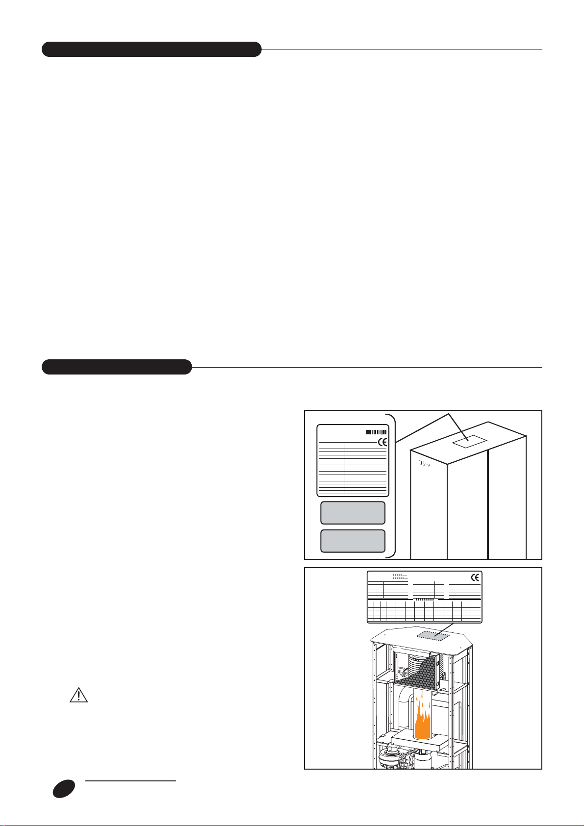
The appliance is identified through:
- Packed label:
A label that indicates the code and the combustion it
uses to identifies the appliance.
- Technical label:
The technical label reports the matrices numbers,
the gas prearrangement, and technical observation.
-Gas prearrangement label:
It reports the kind of gas the appliance has to use,
and if there is a transformation from one kind of gas
to another you have to change the old label.
Spare parts, or technical operation require, a
precise identification of the type of model.
If there is going to be any tampering of the technical
label, this will not consent the right identification of
the apparatus.
The appliance is a gas radiator that heat up the
atmosphere.
It has an intake of air that goes in the combustion
chamber type C.
The appliance is made with an aluminium body that
allows a high efficiency of heat; it also has a fan that
allows the dispersal of air faster in the rooms.
The convectors are arranged in factory for the function at gas methane and they can be transformed to
GPL(G30/G31) using the furnished nozzle kit.
Note: At request the apparatus can be furnished
already arranged at GPL.
It also has an electrical device that allows you to do
a series of things.
There also is a Processor Control Box (P.C.B
assy) that controls all the principals’ function of
the apparatus.
After there is the Control Panel that has other
options.
6
GENERAL
APPLIANCE DESCRIPTION
IDENTIFICATION
Metano
Methane
G.P.L.
L.P.G.
7
GENERAL
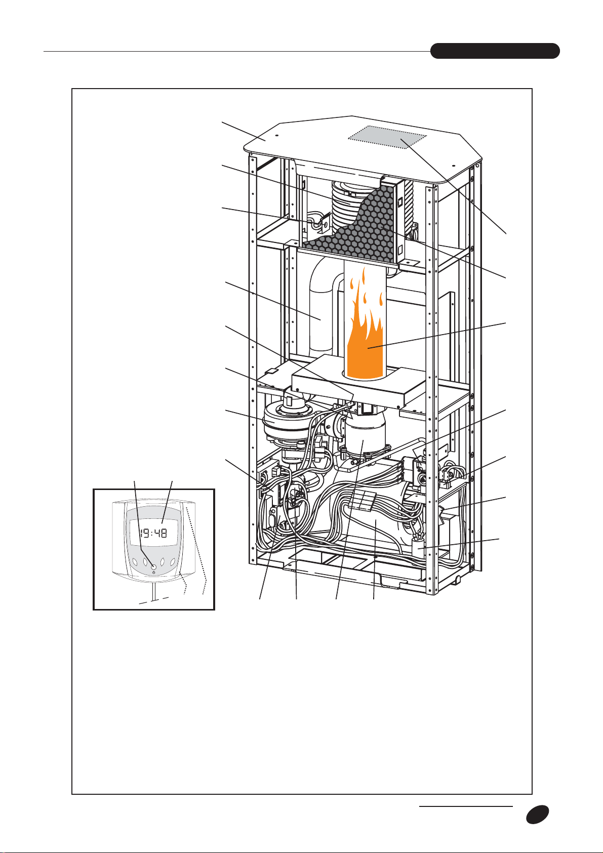
STRUCTURE
3
2
1
4
19
18
5
6
17
16
15
7
8
2324
9
10
20
1 Safety thermostat
2 Heat exchanger
3 Upper cover
4Technical data plate
5 Exchanger cover
6 Glass pipe
7 Gas valve
8 Power plug
9 Gas tap
10 Condenser
11 Convection fan
12 Combustion chamber
21 22
11121314
13 Pressure switch
14 Battery holder (buffer batteries)
15 Control unit
16 Combustion fan
17 Ignition electrode
18 Detection electrode
19 Air extraction pipe
20 Digital control
21 “Split” environment heat probe
22 “Integrated” environment heat probe
23 Display
24 ON/OFF key
The following options are available upon request:
8
GENERAL
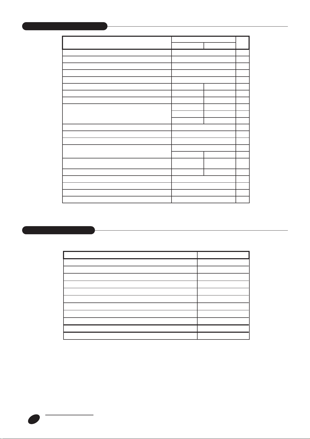
TECHNICAL DATA
ACCESSORIES
MODEL
Terminal capacity nomination (Qn)
Terminal power convector nomination (Pn)
Terminal capacity reduction (Qn)
Terminal power convector reduction (Pn)
Right efficiency
Main pressure (nomination)
Nozzle pressure
Reduce nozzle pressure
Gas consumption (15°C) (nom./red.)
Type of apparatus
Combustion category
Efficiency class
Nozzle
Max/min value Atmospheric
heated by a convector
Quantity of air heated
Electrical alimentation
Power absorbed when in function
Protection degree
Weight with the convector in box
Methane
G30
G31
fiammella
Methane
12,0
7,5
0,407/0,285
C13 - C33 - C53
1,10
95
160
4,5
3,96
3,41
2,9
88
2H 3+
II
1
3
230~50
135
IP20
43
LPG
29/3720
28,8/36,4
17/21
0,354/0,228
0,349/0,225
0,62
95
160
kW
kW
kW
kW
kW
kW
%
mbar
mbar
mbar
3
m
kg/h
kg/h
n°
Ø
m
m3/h
V~Hz
W
kg
/h
3
DESCRIPTION CODE
90° curve _Ø 54mm pipe union
Extension Ø 54mm L = 500mm
Extension Ø 54mm L = 1000mm
90°__curve Ø 54mm cast
135° curves _Ø 54mm
Outer protection grille "GP" for separate end piece Ø 54mm
Outer protection grille "GPu" for combined end piece Ø 54mm
Recessed screen "SDP" for separate end piece Ø 54mm
Stack for pipe Ø 54mm
INSULATION for pipe Ø 54mm L = 1000mm (pack of 4 pcs.)
Inlet/Outlet end piece Ø 54mm L = 6 cm
70000370 00
70000390 00
70000380 00
70000755 00
70000375 00
70000350 00
70000610 00
70000365 00
70000740 00
70000850 00
70000465 00
9
GENERAL
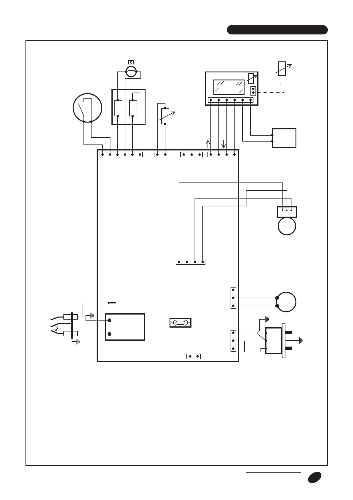
ELECTRICAL SCHEME
TL
2
PS
1 2 3 4 5 6
EV1
1
CN9
3
EV2
4
SE
1 2
CN7
1 2 3
CN8
CR
DDS 174
TX
RX
+
1 2 3 4
CN5
SAS
SAI
-
II
BL
I
RD
0
WH
PP
II I O
V.T.C.
S I T
7530108_0B
T1
ER
TA
SAI INTEGRATED ENVIRONMENT PROBE
SAS SPLIT ENVIRONMENT PROBE
SE EXTERNAL PROBE (optional)
VC COMBUSTION FAN
VTC TANGENTIAL-CENTRIFUGAL FAN
CN... CONNECTOR
T1 POWER TERMINAL
VT TANGENTIAL FAN
TA IGNITION TRANSFORMER
GND/+24V
TX/RX SIGNAL TRANSMISSION/RETURN
BL BLUE LEAD
WH WHITE LEAD
RD RED LEAD
REMOTE CONTROL POWER SUPPLY
4 3 2 1
CN3
F 1AT 250V
CN2
1 2
PP BATTERY HOLDER
SIT CONTROL BOARD
EA IGNITION ELECTRODE
ER DETECTION ELECTRODE
EV1 GAS SOLENOID VALVE
F “1AT 250V” FUSE
CL LINE CONNECTOR
EV2 POWER MODULATOR
L PHASE LINE
N NEUTRAL LINE
CRD DIGITAL REMOTE CONTROL
PS PRESSURE SWITCH
TL LIMIT THERMOSTA T
3 2 1
CN6
3 2 1
CN1
VC
LN
CL
230V~
10
GENERAL
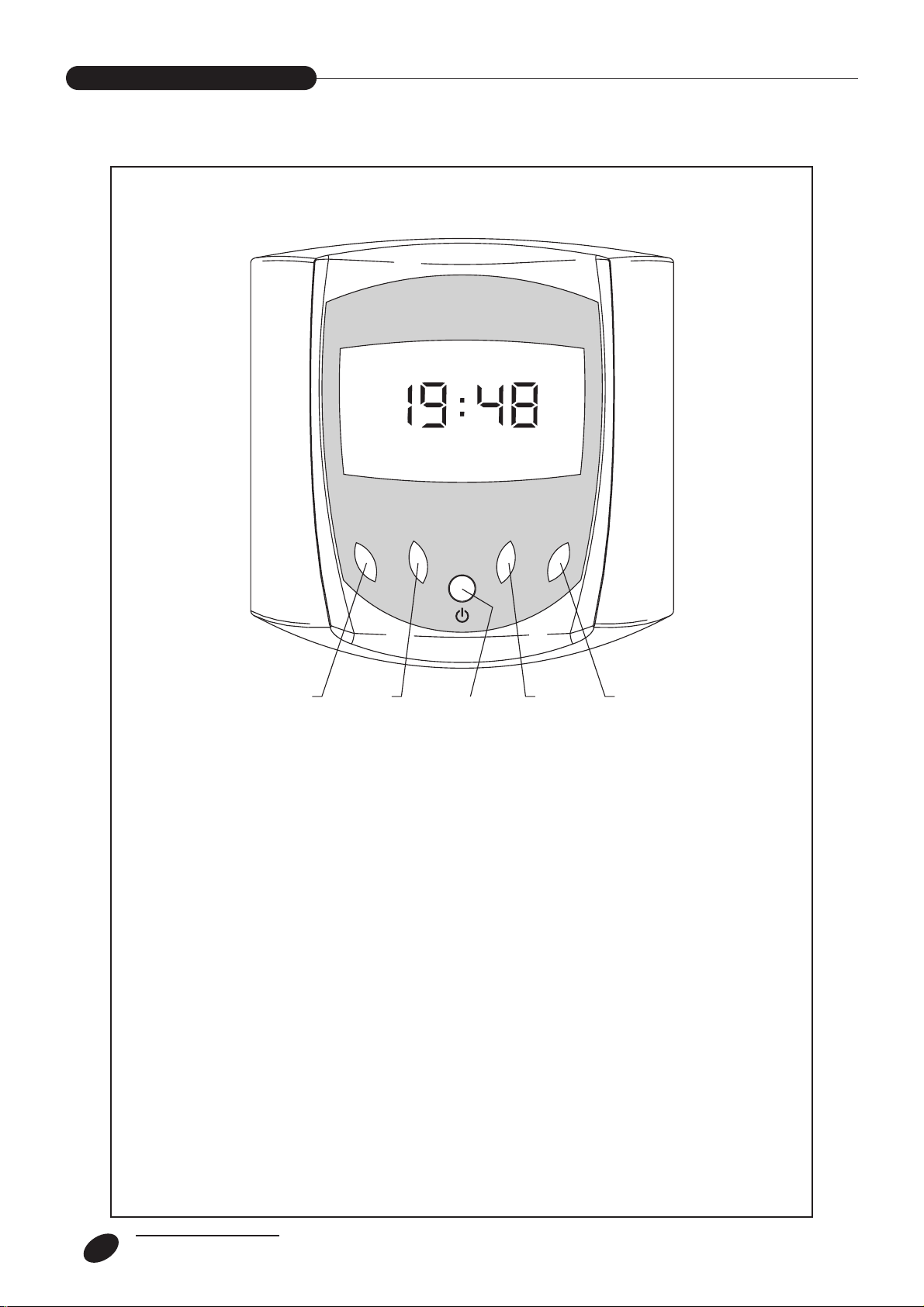
CONTROL PANEL
12345
DESCRIPTION OF KEYS
a - Switch on the appliance (key 3);
b - Press MENU key (key 5);
c - Press DOWN key (key 2) to move the cursor onto the required menu line;
d - Press SELECT key (key 5);
note: keys 1, 2, 4 and 5 acquire different functions in the different menus.
• required setting
e - Press keys 1 and 2 to set the required parameter;
f - Press key 4 to store the parameter just set and pass onto the next;
g - Press OK key (key 5) to store all the set parameters and return to main menu;
The appliance is supplied protected by cardboard
packaging containing:
n. 1 Appliance
n. 1 Digital chronothermostat
n. 1 STANDARD pipe kit
n. 1 Metal template
n. 2 Bracket
n. 1 Documents envelope:
n. 1 User instruction booklet
n. 1 Installer booklet
n. 1 Gas transformation KIT
n. 1 Spare parts catalogue
n. 1 Warranty certificate
n. 1 Warranty labels
n. 1 Power socket
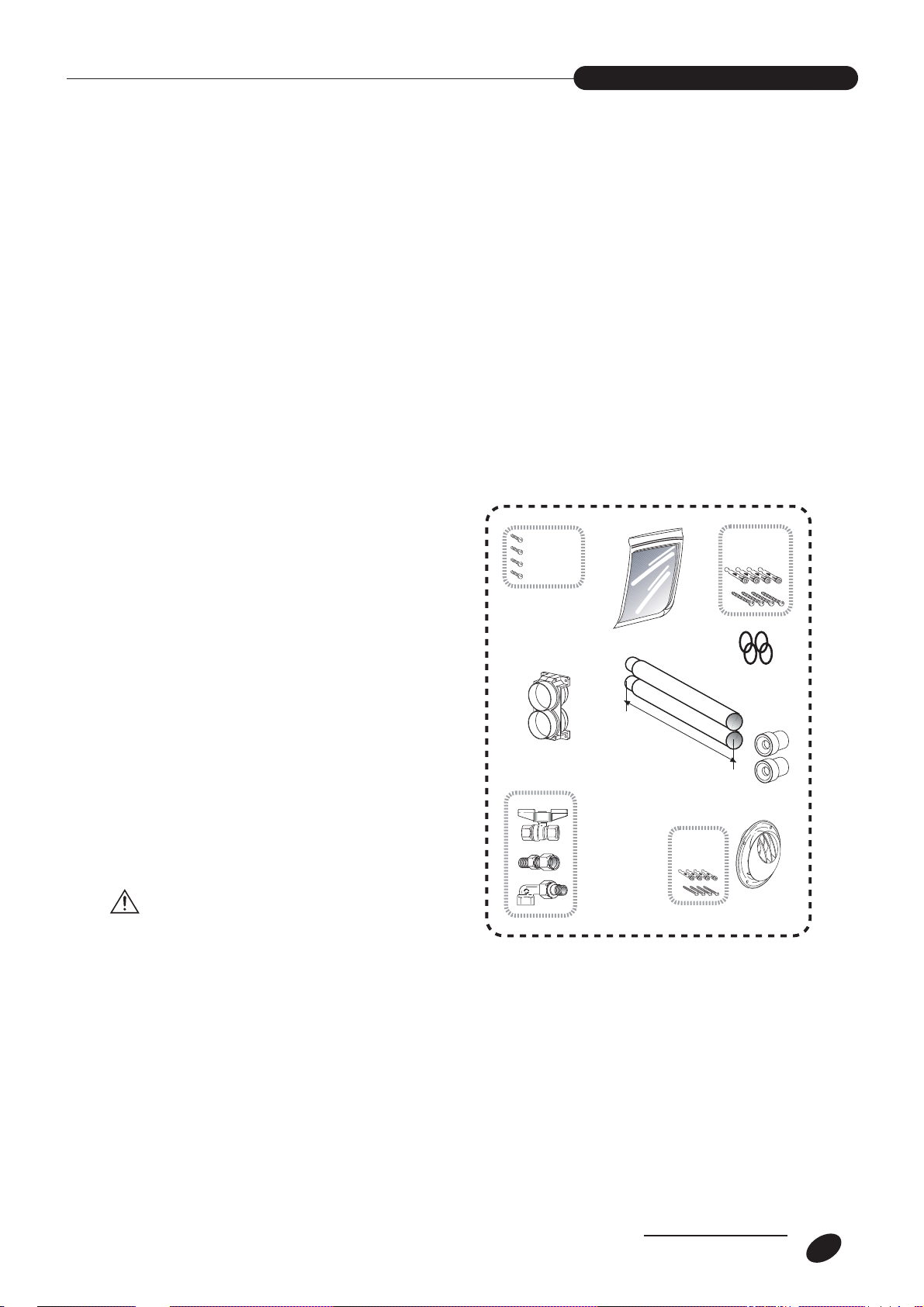
- PARALLEL PIPE KIT WITH SINGLE END PIECE
(STANDARD)
- STANDARD Ø 54 pipe KIT with single end piece
The Kit consists of:
Q.ty Description
1 Gas tap with connections
1 Adapter union for Ø 54 mm pipes
4Ø 3.9 mm screws for fastening adapter
4Ø 8 mm screw anchors for fastening template
2Ø 54 mm pipes, L = 500 mm
1 Single end piece with integrated rosette
4Ø 6 mm screw anchors for fastening
single end piece
2 Diaphragms
4 O-Ring for pipes
For installation see INSTALLER section.
If the STANDARD Pipe KIT inside the appliance
packaging fails to satisfy the desired installation characteristics, new parts can be added (pipes, curves,
etc.) from the Manufacturer’s List.
To avoid any type of breakage or malfunc-
tion that could damage the appliance, we
suggest always using the Manufacturer’s original
accessories and spare parts.
11
INSTALLER
RECEIPT OF PRODUCT
nr. 4
3,9 x 9,5
500
nr. 4
(Ø 6mm)
nr. 4
(Ø 8mm)
nr. 4
O-Ring
Ø110

12
INSTALLER
Verify Tube kit
When the appliance is being installed be sure that all
the tubes are adjusted for the installation you want
done. The tube kits available are:
Cod. TP54OP 0000
Cod. TP5410A5 00
Cod. TP54SP 0000
MODEL CODE
fiammella
nr. 4
3,9 x 9,5
description
KIT std. EXHAUST & INTAKE Ø 54mm (1 INDIVIDUAL)
KIT special EXHAUST & INTAKE Ø 54mm (2 SINGLES)
KIT special EXHAUST & INTAKE Ø 54mm (1 INDIVIDUAL) INTERNAL Installation
TP540P 00000
TP54SP 00000
TP5410A5 00
nr. 4
(Ø 8mm)
nr. 4
O-Ring
nr. 4
3,9 x 9,5
nr. 8
O-Ring
500
mm
mm
1000
500
nr. 4
(Ø 6mm)
Ø110
nr. 4
(Ø 8mm)
500
mm
 Loading...