


Mod. 12 kW
0694
BR0969
Decorative outdoor gas heater.
Decorative outdoor-Heizofen.
Decorative outdoor gaskachel.
Décoratif extérieur chauf fage au gaz.
UK - USER MANUAL AND ASSEMBLY INSTRUCTIONS
DE - GEBRAUCHSANLEITUNG UND DIE AUFBAUANLEITUNG
NL - INSTALLATIE-INSTRUCTIES EN GEBRUIK
FRA - INSTRUCTIONS D'INST ALLATION ET D'UTILISA TION

Manuale h MAX 736, Ø MAX 310
Manual
1
20
18
Telecomandato h MAX 706, Ø MAX 310
Remote
2
3
56
7
16
9
10
11
12
13
14
15
17
19
4
8
Fig.3
1
KEY: 1) fastening knob, 2) cover dish, 3) exchanger head, 4) net cylinder (optional), 5) structure upright, 6)
1 2 3 4
5 6 7 8
Aria compressa
Compressed air
nr.
19
nr.
8
protection grid, 7) glass pipe, 8) retention screw, 9) burner, 10) ignition/adjustment knob, 11) battery holder,
12) control unit (remote control Mod.), 13) tank support base, 14) side panel, 15) control cover panel, 16)
fastening knob, 17) control unit display slot (remote control Mod.), 18) trolley (optional), 19) Hurricane KIT,
20) SMALL remote control (remote control Mod.).
ZEICHENERKLÄRUNG: 1) Befestigungsknopf, 2) Abdeckungsschirm 3) Wärmeaustauscherkopf, 4) Walze netz
Option), 5) Strukturpfosten, 6) Schutzgitter, 7) Glasrohr, 8) Befestigungsschraube, 9) Brenner, 10) Einschalt-
(
/Einstellknopf, 11) Batteriefach, 12) Steuereinheit (Mod. Mit Fernbedienung), 13) Gasflaschenstützfläche, 14)
seitliche Verkleidungstafel, 15) Verkleidungstafel der Bedienelemente, 16) Befestigungsknopf, 17) Aussparung
Display Steuereinheit (Mod. Mit Fernbedienung), 18) Schlitten (Option), 19) Gegen wind, 20) klein
Fernbedienung (Mod. Fernbedienung).
1) Schroeven, 2) Reflector, 3) branderkop, 4) warmteverdeler 5) rechte structuur, 6) beschermingsroosters, 7)
glazen buis, 8) aanhoudperiode schroef 9) brander, 10) ontsteking / aanpassing knop, 11) batterij houder,
12) controle-eenheid (afstandsbediening Mod.), 13) gasfles draagvlak, 14) zij paneel, 15) paneel van de
gascontrole kant, 16) bevestigings knop, 17) controle-eenheid met sleuf (afstandsbediening Mod .), 18) wielset
(optioneel), 19) afstandsbediening (afstandsbediening Mod.).
LÉGENDE: 1) bouton de fixation, 2) la parabole de couverture, 3) l'échangeur, 4) l'échangeur de chaleur, 5)
Structure verticale, 6) la grille de sécurité, 7) tube de verre, 8) vis de fixation, 9) brûleur, 10) le bouton on /
cadre, 11) batterie, 12) unité de contrôle (à distance), 13) appui de base du cylindre, 14) le panneau latéral,
15) panneau de couverture, 16) de fixation mâle, 17) slot unité d'affichage (Mod . télécommande), 18) chariot
(facultatif), 19) Télécommande (mode à distance).
TOOLS recommended for fitting and/or maintenance (not supplied by the Manufacturer): 1) brush for cleaning the glass pipe, 2)
cross-headed tip screwdriver, 3) LPG pressure regulator, 4) 19 fixed wrench for regulator, 5) 8 fixed wrench, 6) scratchproof soft cloth for outside cleaning, 7) protection gloves for transport, 8) compressed air for inside cleaning.
Empfohlene WERKZEUGE für Montage und Wartung (nicht vom Hersteller geliefert): 1) Bürste zum Reinigen des Glasrohrs, 2)
Kreuzschraubenzieher, 3) LPG-Druckregler; 4) 19-Maulschlüssel für den Regler; 5) 8,6-Maulschlüssel; 6) weiches, nicht
scheuerndes Tuch zur externen Reinigung; 7) Schutzhandschuhe für den Transport; 8) Druckluft zur internen Reinigung.
2
F
MIN
500
680
L 640
range of action 2m
h 2180
1436
raggio azione 2m
MIN
500
ig.1
Fig.2
3

1
3
2
1
2
3
1,5Volt
torcia
KD
D
AM1
R14
1,5Volt
ministilo
K3A
AAA
AM4
1,5Volt
stilo
KAA
AA
AM3
Fig.4
1
2
3
4
1
2
3
4
Fig.5
Fig.6
4

1
1
1
2
4
5
8
7
10
11
9
12
Fig.7
1
1
2
10
11
9
5
13
7
12
14
15
16
1
4
1
2
3
5
6
7
8
4
Fig.8
Fig.9
5
Fig.10
1
2
2
Fig.11
Fig.12
6
2
1
UK - HURRICANE KIT ASSEMBLY
1 2
4 5 6
3
optional
E - MONTAGE GEGEN WIND
D
ig.13
F
UK - TUBE MAINTENANCE
DE - WARTUNG TUBE
Fig.14
7

centralina/control unit
telecomando/remote control
Fig.15
UK - DUNP-SWITCH SAFETY DEVICE
DE - SAFETY DEVICE ANTI-KIPPEN
Fig.16
8

1 2 3
4 5 6
1 2 3
UK - REPLACING BROKEN PIPE
DE - ERSATZ GEBROCHEN TUBE
ig.17
F
UK - FIXING THE TANK
DE - FESTSETZUNG DER TANK
Fig.18
8a
G30 • G31
model
Power supply
Thermal capacity Nom.
Thermal capacity Red.
Pressure Nom. supply
Pressure Nom. nozzle
Gas consumption (Qn) (15°C)
Consumption G30
Consumption G31
Tipo apparecchio
Gas category
Burner nozzle
Ø
Pilot nozzle
Ø
Ø Diaphragm
G20 G20 • G25 G25
kW
kW
mbar
mbar
m3/h
Kg/h
Kg/h
nr.
mm
nr.
mm
mm
Manual performant Remote performant
12,00
4,50 6,40 6,00
28-30 • 37
20 20 • 25
20
50 • 50
5,20
28-30 • 37
20 20 • 25
20
50 • 50
-
1,14 1,14 • 1,33 1,33
- - -0,872
- - -0,858
A1
I2H I2E
I2E+ I2LI3+ I3B/P
1
1,65 2,50
1
0,25 0,35
np
np
1,75
G30 • G31 G20 G20 • G25 G25
12,00
5,20 6,40 6,00
28-30 • 37
20 20 • 25
20
50 • 50
6,20
28-30 • 37
20 20 • 25
20
50 • 50
-
1,14 1,14 • 1,33 1,33
- - -0,872
- - -0,858
A1
I2H I2E
I2E+ I2LI3+ I3B/P
1
2,10 3,30
1
0,25 0,35
np
np
1,75
- -
8b
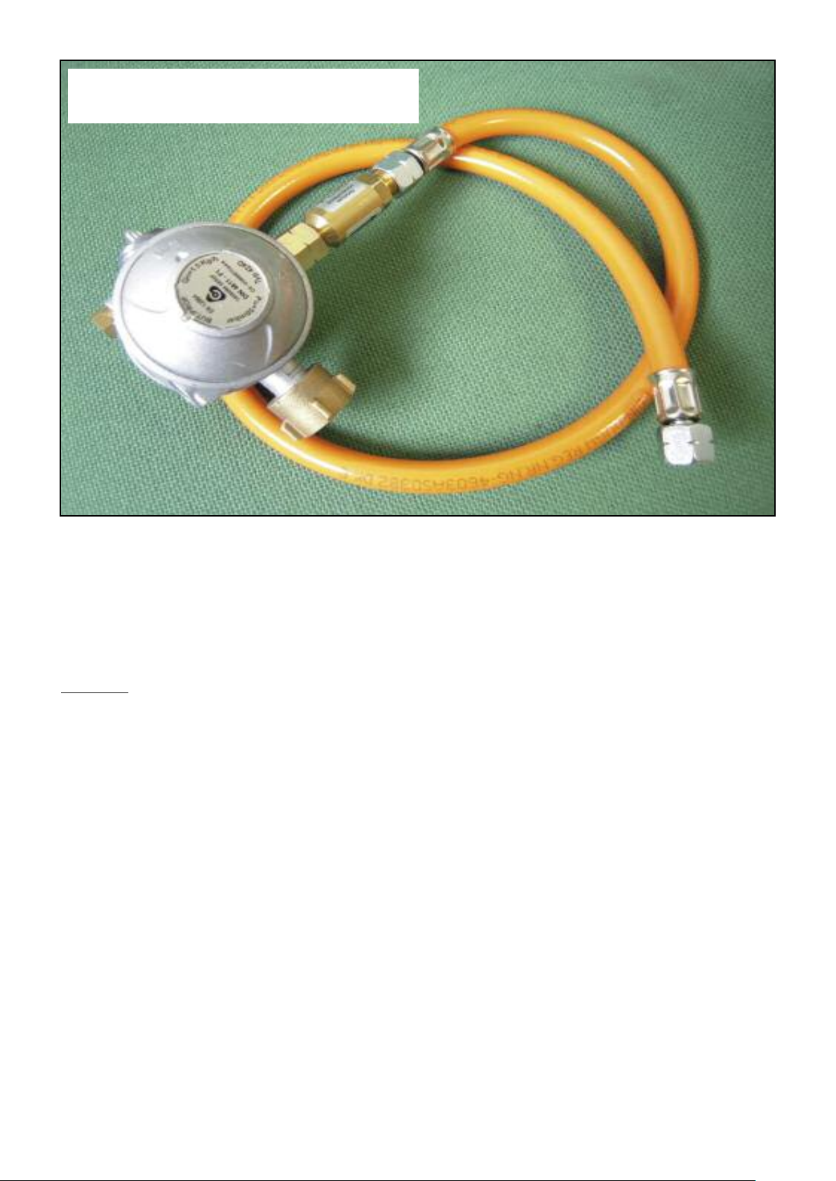
ITA - REGOLATORE PER GERMANIA (50 mbar)
UK - GAS GOVERNOR FOR GERMANY (50 mbar)
DE - DRUCKGAS REGLER FUR DEUTSCHLAND (50 mbar)
UK - REGULATOR: Capacity MAX 1000 g / h, Max pressure 37mbar.
UK - The gas pipe must be of a flexible type and of a length such as to allow an easy replacement of the cylinder.
- UK -
Contents
THE REMOTE CONTROL
GENERAL DESCRIPTION
ASSEMBLY
START-UP
SWITCH-OFF
MAINTENANCE
STORAGE
WARRANTY
TROUBLESHOOTING
9

CAREFULLY LOOK AFTER THIS BOOKLET FOR THE ENTIRE LIFE OF THE APPLIANCE
AND REQUEST A NEW ONE IN CASE OF DAMAGE OR LOSS!
IMPORTANT! SHOULD THE PARTS BE DAMAGED, DO NOT GO AHEAD WITH ASSEMBLY!
IMPORTANT! This appliance must be installed in compliance with the Regulations, Laws and
Standards applicable in the Country of use. Install the appliance outdoors in a well ventilated
area, the area around the appliance must have an open side of MIN 25% of the total area, the
use must comply with the instructions provided by the manufacturer. Refer to the instructions before installing and using the appliance.
IMPORTANT! ALL the maintenance, repair or modification operations MUST be performed
by professionally qualified and certified personnel and always using the Manufacturer’s
original spare parts.
IMPORTANT! This gas-fuelled appliance is a heat generator intended only for the use for which
it was designed and certified (with room temperature NOT below 0°C for Remote-controlled
mod.), or as an appliance for heating open, ventilated or outdoor environments. All other
uses are to be deemed improper and therefore hazardous. The Manufacturer disclaims all
liability for any injury to persons or animals or damage to things caused by improper use.
IMPORTANT! If exposed to violent gusts of wind, provide adequate anchorage to the slab.
IMPORTANT! OPERATION IN CLOSED ENVIRONMENTS IS FORBIDDEN: OFFICES, INSIDE HOMES, STABLES, ANIMAL FARMS, PLACES NEAR GAS VAPOURS OR POTENTIALLY INFLAMMABLE DUSTS AND/OR EXPLOSIVES, ETC.
IMPORTANT! Carefully follow ALL the instructions and precautions indicated in this
booklet (concerning INSTALLATION, USE and MAINTENANCE). Failure to abide by these
instructions could cause malfunctions and or endanger people, animal and things.
IMPORTANT! THIS APPLIANCE IS GAS FUELLED AND PARTS OF IT BECOME HEATED.
CONSEQUENTLY, KEEP IT OUT OF REACH OF CHILDREN.
IMPORTANT! NEVER move the appliance with the burner still operating.
IMPORTANT! ALWAYS COMPLY WITH SAFETY DISTANCES FROM OBJECTS OR
INFLAMMABLE MATERIALS(Fig. 2).
IMPORTANT! TO ASSEMBLE AND USE, ABIDE BY THE FIRE-FIGHTING AND ACCIDENTPREVENTION REGULATIONS OF THE COUNTRY WHERE THE APPLIANCE IS USED.
IMPORTANT! DO NOT use the appliance set for LPG in basements or cellars.
IMPORTANT! The appliance made to use LPG, CANNOT be fed with or modified to use
natural gas and vice versa.
IMPORTANT! MODIFYING the appliance is absolutely forbidden except ONLY in those cases
indicated and authorised by the Manufacturer.
IMPORTANT! Fit the gas pressure regulator on the cylinder (fixed-setting type) in conformity with the TECHNICAL DATA and GAS SETTING plates on the appliance (Tab. 1).
IMPORTANT! Every time the cylinder is changed and periodically, using soapy water or
equivalent, make sure there are NO gas leaks from the pipes, from the cylinder connections, gas distribution connections and gas connection with the appliance. Replace the
seal every time the cylinder is changed and periodically check the state of wear, efficiency,
tube expiry data and all the connections.
IMPORTANT! Before making the connection, make sure the hose connector provided is in
conformity with the Regulations applicable in the Country of use.
IMPORTANT! Before proceeding with assembly operations, make sure all the parts making up
the appliance are suitable for the type of gas and pressures according to the Regulations applicable in the Country of use.
10

GENERAL DESCRIPTION
Due to its specific type of operation with direct and reflected irradiance, this appliance approximately heat up a surface of 13 m
2
with a range of action of 2 meters. The weather of your specific region could influence the device efficiency, as the appliance position (totally or in part
open space) as your subjective heating feelings. The heating feeling substaintially increases
close to the appliance.
The appliance is very simple to use and built according to CE safety standards. It has been
tested, approved and controlled by the Notified Approval Institute to which the Manufacturer has
always entrusted most of its certifications in the gas industry.
Types of installation:
- MOBILE, with the base free of restraints using the trolley (optional), with LPG fuel only (tank).
- FIXED, with the base fastened to the floor (this type of installation must be carried out only by
professionally skilled personnel), using Propane/Butane gas (large tank) or natural mains gas.
ASSEMBLY
Take all the parts making up the appliance out of the packaging, with special care given to the
burner unit (Fig. 3: 3, 4, 7, 9, 10).
Check the integrity and the conformity of the contents of the packaging (the latter must be
disposed of according to applicable regulations):
A - Mod. FALO’ with manual controls
- Appliance with carrying structure and special-glass pipe;
- Hose connection (make sure this complies with applicable regulations);
- Cover dish;
- Multilingual instruction booklet;
- Warranty Certificate.
B - Mod. FALO’ with Remote Control
- Appliance with carrying structure and special-glass pipe;
- Hose connection (make sure this complies with applicable regulations);
- Cover dish;
- Multilingual instruction booklet;
- Warranty Certificate.
IMPORTANT! Always wear individual hand protection gear during appliance assembly and
positioning. Use the special accessory for moving (Fig. 3:18) to prevent cuts and burns.
ASSEMBLY OPERATIONS (MOBILE type with LPG tank):
Before starting assembly operations, remove any guards.
1 – Delicately place the structure on the ground and fit the cover dish (Fig. 3: 2).
2 – Remove the side panels (Fig. 3: 14, 15) and position the tank on the base plate (Fig. 3: 13).
3 – Fit the gas pressure regulator on the cylinder (fixed-setting type) in conformity with
the TECHNICAL DATA and GAS SETTING plates on the appliance (Tab. 1 or 2).
4 – Purchase the connector and the rubber connection hose separately. These must be of the type
and materials required by the Regulations of the Country of use (if those already provided do NOT
conform).
11

The threaded end part, meaning the adapter (Fig. 9: 4) permits various kinds of connections.
IMPORTANT! two types of adapters exist, one left turning (SWITZERLAND, AUSTRIA, GERMANY and LUXEMBOURG) and one right turning (all other countries).
CASE A (Fig. 9: A) 1/4” gas left turning: fit the rubber hose (1), featuring a specific threaded
connector (SUPPLIED). This solution is suitable for SWITZERLAND, AUSTRIA, GERMANY
and LUXEMBOURG.
CASE B (Fig. 9: B) 1/4” right turning: fit the rubber hose (6) purchased separately (if that already
provided does NOT comply) directly on the threaded 1/4” GAS right turning connection (4) of the
end part ; now fit the rubber hose (8- MAX Length = 1.5 m) using the clamp provided (6).
5 – Fasten the lower part of the gas connection hose to the regulator (Fig. 9: 2) on the tank (Fig.
9: 3). Connect the other end of the gas hose to the connection.
6 – Before making the connection, check to see whether the gas diaphragm (Fig. 9: 5) must be
fitted on the entry connector (Fig. 9: 4) (solution valid for SWITZERLAND, AUSTRIA, GERMANY and LUXEMBOURG - see Tab. 1 or 2).
IMPORTANT! DO NOT FIT the diaphragm on appliances fuelled with gas G30/G31 at 29÷37 mbar.
IMPORTANT! ONLY FIT the diaphragm in case of operation with supply pressure 50 mbar
(Switzerland, Austria, Germany, Luxembourg). Check the correct type as specified and
shown on Tab. 1 or 2.
7 – Delicately tilt the appliance, position the cover dish (Fig. 3: 2) and fasten in position with the
knobs provided (Fig. 3: 1) and return the appliance to vertical position.
IMPORTANT! NEVER rest the top end of the appliance on the ground, especially when the
cover dish is fitted to avoid damaging the gas seals, the glass pipe or obstructing the gas pipe.
8 – Connect the gas supply pipe to the bottom part of the connection (already fitted) (Fig. 7 and 8: 12).
ASSEMBLY PHASES (FIXED type, on ground or floor, with LPG tank or mains gas supply):
IMPORTANT! If the appliance is used with LPG at 50 mbar (for SWITZERLAND, AUSTRIA,
GERMANY and LUXEMBOURG), fit the conforming diaphragm, see Technical Data table.
1 – Delicately rest the structure on the ground and fit the cover dish (Fig. 3: 2).
IMPORTANT! NEVER rest the top end of the appliance on the ground, especially when the
cover dish is fitted, to prevent damaging the gas seals, the glass pipe or obstructing the gas pipe.
2 – Position the appliance taking into account the position of the supply pipe and remove the
side panels (Fig. 3: 14, 15).
3 – Mark the position of the fastening holes on the ground.
4 – Fasten the structure to the ground using anchor bolts (Fig. 11: 1, NOT provided) suitable for
the type of floor, making use of the holes (Fig. 11: 2) made in the tank support base.
5 – Separately purchase the connector and connection pipe, of a type and material suitable for
the Regulations of the Country of use, and connect directly on the _” right-threaded GAS connector (4) on the end part of the coupling, and then fasten the rubber hose (8 with MAX length =
1.5 m) using a clamp (7).
6 – Before making the connection, check to see whether the gas diaphragm (Fig. 9: 5) needs
fitting on the inlet connection (Fig. 9: 4) (solution valid for SWITZERLAND, AUSTRIA, GERMANY and LUXEMBOURG - see Tab. 1 or 2).
IMPORTANT! DO NOT FIT the diaphragm on appliances fuelled with gas G30/G31 at 29÷37 mbar.
IMPORTANT! ONLY FIT the diaphragm in case of operation with supply pressure at 50 mbar
(Switzerland, Austria, Germany, Luxembourg). Now check the correct type as indicated and
illustrated in Tab. 1 or 2.
7 – Make sure the type of gas and the supply pressure correspond to those on the plate (see
Table), if necessary fit a pressure reducer/regulator (NOT supplied).
8 - Purchase the connector and the rubber connection hose separately. These must be of the
12

type and materials required by the Regulations of the Country of use (if those already provided
do NOT conform).
IMPORTANT! MAKE SURE THE SUPPLY PIPE AND GAS CONNECTOR COMPLY WITH
THE STANDARDS REQUIRED BY THE COUNTRY OF USE.
9 – Connect the gas supply pipe to the lower part of the connector (already fitted) (Fig. 7 and 8: 12).
Fitting the battery (for electronic Pilot ignition):
1 – remove the tank cover side panel (Fig. 3: 14) by loosening the screw (Fig. 3: 8);
2 – after locating the battery cylinder (Fig. 4: 1), remove the cover (Fig. 4: 2) and fit the battery
Type AA (Fig .4: 3) respecting the right polarity.
3 – fit everything back correctly in the opposite sequence.
START-UP
IMPORTANT! USE OF THIS PRODUCT IN CLOSED CAN 'BE A SOURCE OF DANGER
AND' PROHIBITED.
IMPORTANT! Remove all the protective films if fitted.
IMPORTANT! Use LPG tanks taking into account the size of the tank compartment (Fig. 3: 13).
IMPORTANT! To prevent any blaze-ups due to gas accumulation, allow 1 or 2 minutes to pass
before repeating the ignition procedure.
NOTE: when first igniting, due to the air in the pipes, the pilot flame tends to go out.
Wait a while before attempting to ignite again (at most 2 or 3 times) until the flame stabilises! If the fault continues, try and identify the cause, see Troubleshooting Section.
- If the pilot should accidentally go out, the incorporated safety device will automatically interrupt the gas supply.
- If the flame goes out for want of gas, the gas flow is interrupted (for example when the gas
cylinder is empty).
- In both cases, you must wait a few minutes before restarting the heater. Then repeat the operations mentioned in points 1 and 2.
- Do not try to restart the heater time and again; if the heater does not work, you should check
whether ALL operations have been carried out correctly.
IMPORTANT! NEVER start the appliance without first fitting the cover dish and fully completing
assembly. The burner unit and the glass pipe must NEVER be covered or partially covered.
IMPORTANT! DO NOT cover the appliance if this has only just been switched off. Wait for it to
cool down.
IMPORTANT! Protect the appliance against knocks. Always place the appliance on fairly flat
surfaces to prevent it overturning (gradient < 10°) and on non-inflammable surfaces (wood, linoleum, synthetic floors, etc).
IMPORTANT! The appliance is equipped with a safety device (Fig. 16) that extinguishes the
flame in case of surface with slope greater than 15°.
IMPORTANT! WHEN FIRST STARTED – IN THE OPEN AIR OR WELL-VENTILATED ENVIRONMENT – THE APPLIANCE COULD GIVE OFF VAPOURS OR SMELLS FOR A SHORT TIME.
IMPORTANT! Do not block the openings provided for ventilation of the cylinder holder and the
burner assembly.
IMPORTANT! CLOSE VALVE MAIL ON THE BOTTLE AFTER USE.
Ignition – MANUAL mod.
Regulation sequence, turn knob: OFF, spark ON, MIN and MAX;
1 – Make sure the ignition/regulation knob (Fig. 3: 10) is in OFF position (Fig. 5: 1) and open
13

the gas supply tap.
2 – Push and turn the ignition/regulation knob (Fig. 5) anticlockwise. The spark discharge and
gas opening for pilot ignition will start automatically.
Once the flame has ignited, continue to press the knob for about 15 seconds to allow the thermocouple to heat up and keep the valve open. At this point, simply regulate the burner power:
Ignition – REMOTE CONTROL mod.
WARNING! Some infrared remote controls, if pointed directly to the appliance may interfere
with its operation.
Regulation sequence, by pressing the button on the remote control or directly on the control
unit: ON, MAX, MEDIUM, MIN and OFF.
1 – Keep the ON/OFF button on the control unit (Fig. 6) pressed for about 4” until ignition
occurs. Once ignited, every time the ON/OFF button is pressed the appliance switches from
MAX to MEDIUM to MIN flame and finally OFF.
IMPORTANT! This ignition delay is not a “fault” in the electronic control unit but has been purposely designed by the Manufacturer to ensure appliance safety and prevent accidental ignition.
IMPORTANT! If the pilot flame goes out, accidentally or due to lack of gas, the gas supply will
be automatically interrupted by means of the installed safety device.
IMPORTANT! Avoid repeated ignition attempts: if the appliance does not operate immediately, make sure ALL the installation operations have been performed correctly.
IMPORTANT! During operation and also after switch off, DO NOT TOUCH the protection gril-
les, the burner unit, the glass pipe and the cover dish. These are hot and could cause burns.
Power adjustment can also be made during appliance operation:
- MANUAL mod. (Fig. 5), by means of the ignition and adjustment knob.
- REMOTE CONTROL mod. (Fig. 6), by means of the remote control and with the button located on the control unit.
IMPORTANT! If the appliance is fuelled by LPG in the open air and with temperatures below
2°C the use of Propane gas is recommended.
SWITCHING OFF
A - MANUAL mod.:
1 – Remove the side cover (Fig. 3: 15).
2 – Turn the control knob clockwise, returning this to position "0" (Fig. 5: 1).
3 – Correctly fit the side cover back on in reverse sequence.
B – REMOTE CONTROL Mod.:
1 – Press the ON/OFF button on the remote control (Fig. 6) or on the control unit on board the
appliance (Fig. 6).
2 – Remove the side cover (Fig. 3: 14 - 15) and close the gas supply tap.
IMPORTANT! IF THE APPLIANCE IS NOT USED FOR A LONG PERIOD, REMOVE THE
IGNITION BATTERIES (Fig. 4: 3), OF THE REMOTE CONTROL AND OF THE REMOTE
CONTROL UNIT (Fig. 4: 3) FROM THEIR HOUSING, TO PREVENT CORROSIVE LIQUID
LEAKING OUT AND CAUSING DAMAGE.
14

MAINTENANCE
IMPORTANT! BEFORE PERFORMING ANY TYPE OF MAINTENANCE, MAKE SURE THE
GAS SUPPLY TAP AND/OR BURNER SUPPLY TAP ARE CLOSED.
REPLACING THE BOTTLE
1 - Make sure the appliance is completely cold;
2 - Remove the tank cover side panel (Fig 3: 15);
3 - Remove the cylinder from the cylinder holder;
4 - Disconnect the pressure regulator from the cylinder valve;
5 - Check the state of efficiency of the gas supply pipe visually (presence of cracks) and
checking the expiration date stamped;
6 - Check the efficiency of the regulator while verifying the presence and condition of the seal
gas (if replacement is recommended at each change cylinder);
7 - Connect the new bottle and store it in the compartment;
8 - Check the perfect gas circuit with soapy water or specific products;
9 - Replace the side panel.
IMPORTANT! After replacement of the cylinder, the first attempts at ignition may occur with longer times due to the possible presence of air in the pipeline.
Maintenance concerns:
Cleaning the inside of the glass pipes: use a non-metal pipe-brush (optional) to remove traces
of dirt and/or soot.
IMPORTANT! Dry clean with a soft cloth. The use of liquid products could create deposits and/or encrustations that are hard to eliminate.
- Cleaning the outside of the appliance (use a soft cloth and neutral cleaning products and
avoid pouring these directly on the part to be cleaned).
- Control or replacement of the rubber gas hose (max L = 1.5m), whenever damaged and
according to the schedule provided by Laws and Standards applicable in the Country of use.
- Checking the integrity of all the parts making up the appliance; in case of wear or breakage,
only replace with the Manufacturer’s original spare parts.
- replacing batteries for electronic ignition (Fig. 4: 3) or in the Remote Control unit (Fig. 4: 3).
NOZZLE REPLACEMENT (by professionally qualified personnel)
1 – Remove the tank cover side panel (Fig. 3: 15);
2 – Loosen the retention screws (Fig. 7: 1) of the tap and burner drawer (Fig. 7: 2).
3 – Move the burner unit (Fig. 7: 4) so as to make the nozzle accessible.
4 – locate the nozzle (Fig. 7: 5), unscrew it delicately from its housing, and replace it, being
VERY CAREFUL NOT TO DAMAGE THE THREADED PARTS.
5 – Fit the new nozzle back on (always for the same type of gas) and delicately fully tighten.
6 – Fit everything back on in the reverse sequence.
IMPORTANT! The appliance MUST NOT under any circumstances, be transformed from Natural
Gas to LPG or vice versa. Any attempt at transformation is hazardous and the Manufacturer
disclaims all liability in the event of any injury to persons or damage to things deriving from this
operation or any other tampering. The appliance must therefore ONLY be assembled by the
Manufacturer and ordered by the user directly for the type of gas to be used to fuel it.
15

STORAGE AND HANDLING
IMPORTANT! Moving the unit (Fig. 12) just after turning it off, let it cool completely closed and the gas supply.
If the appliance is not used for a long time (change of season or other reasons), follow the
instructions below:
- Store the appliance in a dry place, protected against any possible damage.
- ALWAYS cover the burner unit and base to avoid obstructions (cobwebs, dust) or damage
(denting, weather conditions, etc.).
IMPORTANT! NEVER store the appliance together with one or more gas tanks. These must
always be kept in outside premises and in conformity with the Law and Regulations applicable
in the Country of use.
WARRANTY
Your appliance is covered by a two-year warranty starting on the day of purchase.
The warranty covers all manufacturing faults except those caused by use of the appliance in a
way different to that specified and intended by the Manufacturer.
The warranty starts on the date indicated on the purchase and cash receipt.
This appliance is not intended for professional uses.
Wear, corrosion, any deformation, decolouring or burnishing (especially of aluminium, satin-finish parts or the glass pipe) due to contact with the flame and continuous heat radiation are to be
considered normal and under no circumstances can be considered manufacturing defects.
These are caused by normal wear and tear.
It is also normal, after prolonged use, for worn parts to be replaced ALWAYS using the
Manufacturer’s original spare parts and having maintenance/repairs done by professionally-qualified personnel authorised by the Manufacturer.
16

TROUBLESHOOTING: with remote control.
FAULT CAUSE REMEDY
When ignited the appliance does not work,
The POWER indicator does not come on.
1-Battery charge too low, battery pack
faulty (B1) or poles loose.
2-Infra-red receiver (D) covered.
3-The POWER button of the remote control
has not been pressed for 2 seconds.
4-Remote control faulty or batteries low.
5-Connection cables between front and
rear control boards loose or faulty.
6-Control boards faulty.
7-Dump-switch failure or the floor with
inclination greater than 15¡.
1-Replace batteries, tighten poles
2-Make hole for receiver.
3-Press POWER for 2 seconds, release and
press again.
4-Replace Remote Control or Batteries
5-Remedy or replace.
6-Replace.
7-Replace, change position (floor with
inclination less than 15¡).
No spark when the appliance is started.
1-Distance between the ignition device
(HV1) and th e ear th connection or the dist ance
between the electrodes (HD) is excessive.
2-The ceramic p art of the ignition devi ce (H V1)
is broken or faulty.
3-High-voltage cable loose, broken or shortcircuited.
4-No earth connection in pilot set.
5-Rear control board faulty.
1-Regulate the distance to 4 __0.5 mm.
(Th e cable resistan ce mus t be connected close
to the ignition device).
2-Replace the ceramic part.
3-Repair or replace.
4-Make earth connection.
5-Replace.
No flame
1- Not en ough gas sup ply (bad LPG ga sifi cat ion
or dirt in system) or pressure regulator not set
properly or faulty.
2-No gas flow (tank empty or interruption in
supply) or pressure regulator faulty.
3-Sudden gust of wind (above 3 m/s) with
gas tank panels removed.
4-Dirt in gas circuit.
5-Gas leaks.
6-cylinder connection, air in pipe
1-Clean, set / replace.
2-Check / replace.
3-Replace panels.
4-Check / clean.
5-Ch eck/ tigh ten connec tion s/re place se als o r pip es.
6-repeat ignition to eliminate air.
Spark ok but pilot flame does not come on.
1-No gas supply.
2-Connection faulty between front and rear
connection boards or power cables loose.
3-Pilot injector blocked.
4-Rear control board faulty.
5-Valves G1 and G2 faulty.
1-Check.
2-Reposition or replace cables.
3-Check or replace.
Nozzle diameter: LPG: 0.35 mm; NATURAL
GAS: 0.55 mm.
4-Replace.
5-Replace.
Pilot flame on, sparks continue without stop
(no flame detection).
1-Flame sensor cables (S) and ignition device
(HV) switched over or loose.
2-Flame sensor (S1) and earth short circuited.
3-Flame sensor (S1) fails to detect flame.
4-Pilot flame burns inside pilot pipe.
5-Rear control board faulty.
1-Put right.
2-Restore correct position.
3-Restore correct position.
4-Replace.
5-Replace.
Pilot flame on, the main burner does not
come on.
1-Cables faulty or terminals loosened.
2-Main burner nozzle blocked.
3-ÒMÓ and ÒLÓ valves faulty.
4-Front and rear control boards faulty.
5-Faulty remote control.
1-Repair or replace.
2-Check gas pressure, replace pilot set or
perforate injector again.
3-Check gas pressure, replace ÒMÓ and ÒLÓ
valves.
4-Replace.
5-Replace.
The low flame comes on; the medium flame
does not.
1-Cables faulty or terminals loose.
2-ÒMÓ valve faulty or ÒMÓ valve nozzle
blocked.
3-Front control board faulty.
4-Faulty remote control.
1-Repair or replace.
2-Replace.
3-Replace.
4-Replace.
The medium flame comes on; the low flame
does not.
1-Cables faulty or terminals loose.
2-ÒLÓ valv e fau lty o r ÒLÓ valve nozzle bloc ked.
3-Front control board faulty.
4-Remote control faulty.
1-Repair or replace.
2-Replace.
3-Replace.
4-Replace.
During the ignition cycles, the appliance does
not go off in 25 seconds.
1-Front control board faulty. 1-Replace.
The remote control battery is down. 1-The battery is failing. 1-Replace.
Blackening of glass pipe
1-poor quality gas or gas unsuitable for winter
2-bad draught.
3-
mains cylinder (optional) out of
position/deformed
.
4-exchanger head dirty/damaged.
5-burner dirty/damaged.
1-use quality gas, preferably pure propane.
2-particularly windy or no wind-protection KIT.
3-reposition/replace/eliminate.
4-clean/replace.
5-clean/replace.
Glass pipe breakage
- excessive thermal shock due to particular
weather conditions.
- cleaning with unsuitable instruments.
- accidental fall of appliance.
- Replace.
- Replace.
- Replace.
17

TROUBLESHOOTING: manual controls.
FAULT CAUSE REMEDY
No flame
1 – non enough gas supply flow:
- bad LPG gasification;
- bad LPG gasification with low temperature.
- pressure regulator wrongly set or faulty.
2 – sudden gust of wind (above 3 m/s).
3 – thermocouple interrupted.
4 – valve magnet faulty.
5 - Dump-switch failure or the floor with
inclination greater than 15°.
6 – dirt in gas circuit.
7 – gas leaks.
8 – battery low.
9 – isolation of electrodes and/or faulty
cables.
1- Check:
- Check and replace empty tank;
- Replace with Propane gas tank.
- Regulate or replace.
2 – keep appliance out of wind.
3 - Replace.
4 - Replace.
5 - Replace, change position (floor with
inclination less than 15°).
6 - Check and clean carefully.
7 - Check and eliminate leak.
8 - Replace.
9 - Replace.
Blackening of glass pipe
1-poor quality gas or gas unsuitable for winter
2-bad draught.
3-
mains cylinder (optional) out of
position/deformed
.
4-exchanger head dirty/damaged.
5-burner dirty/damaged.
1-use quality gas, preferably pure propane.
2-particularly windy or no wind-protection KIT.
3-reposition/replace/eliminate.
4-clean/replace.
5-clean/replace.
Glass pipe breakage
1 - excessive thermal shock due to particular
weather conditions.
2 - cleaning with unsuitable instruments.
3 - accidental fall of appliance.
1 - Replace.
2 - Replace.
3 - Replace.
* Glass pipe breakage
The technical features of the glass pipe are particular and such as to permit resistance to thermal shocks caused by normal temperature fluctuations, rain or damp.
Despite the choice of this material (Borosilicate), sudden pipe breakages can occur as a result
of particular weather conditions and/or excessively concentrated temperature fluctuations.
IMPORTANT! This pipe breakage (crack) does not cause injury to people or damage to
things in the immediate vicinity of the appliance.
IMPORTANT! Any pipe breakage does not, in the short term, prevent the appliance from
operating, but being a damaged part, it must be replaced to ensure correct operation.
18

UK - GAS GOVERNOR FOR GERMANY (50 mbar)
E - DRUCKGAS REGLER FUR DEUTSCHLAND (50 mbar)
D
ITA - REGLER: Kapazität MAX 1000 g / h, Max Druck 37mbar.
ITA - der Gasleitung muß einer flexiblen Art und mit einer Länge, wie beispielsweise sein, einen
einfachen Austausch des Zylinders zu ermöglichen.
- DE -
Inhaltsverzeichnis
FERNBEDIENUNG
ALLGEMEINE BESCHREIBUNG
MONTAGE
INBETRIEBSETZUNG
AUSSCHALTUNG
WARTUNG
AUFBEWAHRUNG
GARANTIE
EVENTUELLE STÖRUNGEN UND ABHILFEN
19

DIESES HANDBUCH FÜR DIE GANZE LEBENSDAUER DES GERÄTS AUFBEWAHREN
UND EIN NEUES ANFORDERN, FALLS ES ZERSTÖRT WERDEN ODER VERLOREN
GEHEN SOLLTE!
WICHTIG! FALLS DIE BAUTEILE BESCHÄDIGT SEIN SOLLTEN, KEINESFALLS DIE
ZUSAMMENFÜGUNG VORNEHMEN!
WICHTIG! Dieses Gerät ist in Übereinstimmung mit den im Bestimmungsland geltenden
Regelungen, Gesetzen und Vorschriften aufzustellen. Stellen Sie das Gerät im Freien in einem
gut belüfteten Raum, muss der Bereich um das Gerät eine offene Seite der MIN 25% der gesamten Fläche zu haben, muss die Verwendung mit den Anweisungen des Herstellers beachten. Vor
der Gerätaufstellung und-Verwendung diese Anleitung lesen.
WICHTIG! ALLE Wartungs-, Reparatur- und Abänderungsarbeiten HABEN durch qualifiziertes
und anerkanntes Fachpersonal unter ausschließlichem Gebrauch der Originalersatzteile des
Herstellers zu erfolgen.
WICHTIG! Dieses mit Gas gespeiste Gerät ist ein Wärmeerzeuger, der nur für den Zweck
bestimmt ist, für den er konzipiert und zertifiziert wurde (bei Umgebungstemperatur von NICHT
weniger als 0°C im Falle der Version mit Fernbedienung), sprich als Gerät zur Erwärmung
von Umfeldern, die offen und belüftet sind oder sich im Freien befinden. Jeder anderweitige Gebrauch ist als unsachgemäß und demzufolge gefährlich zu betrachten. Der
Hersteller kann nicht für eventuelle, durch unsachgemäßen Gebrauch hervorgerufene
Personen- und Sachschäden verantwortlich gemacht werden.
WICHTIG! Wenn zu heftigen Windböen ausgesetzt ist, eine angemessene Verankerung an
der Platte.
WICHTIG! DER BETRIEB IN GESCHLOSSENEN RÄUMEN IST VERBOTEN: BÜROS, WOHNUNGEN, STÄLLEN, VIEHZUCHTEN, ÖRTLICHKEITEN IN NÄHE VON GASDÄMPFEN
ODER STÄUBEN, DIE POTENTIELL ENTFLAMMBAR UND/ODER EXPLOSIV SIND.
WICHTIG! Genau ALLE in diesem Handbuch angeführten Anweisungen und Warnungen
(betreffs AUFSTELLUNG, GEBRAUCH und WARTUNG) befolgen; deren Nichtbefolgung
könnte Ursache von Betriebsstörungen und/oder Gefahren für Personen, Tiere und
Sachen sein.
WICHTIG! DIESES GERÄT FUNKTIONIERT MIT GAS UND HAT HEISSE TEILE, WESHALB
ES AUSSERHALB DER REICHWEITE VON KINDERN GEHALTEN WERDEN MUSS.
WICHTIG! Das Gerät NIEMALS versetzen, wenn der Brenner noch in Betrieb ist.
WICHTIG! ES SIND UNBEDINGT DIE SICHERHEITSABSTÄNDE VON GEGENSTÄNDEN
UND ENTFLAMMBAREN STOFFEN EINZUHALTEN (Abb.2).
WICHTIG! BEI DER MONTAGE UND VERWENDUNG SIND DIE IM BESTIMMUNGSLAND GELTENDEN BRANDSCHUTZ- UND UNFALLVERHÜTUNGSVORSCHRIFTEN ZU BEFOLGEN.
WICHTIG! Das für Flüssiggas vorbereitete Gerät NICHT in Kellern oder unterirdischen Geschoßen
verwenden.
WICHTIG! Das vom Hersteller zur Versorgung mit Flüssiggas erzeugte Gerät, darf NICHT
zur Versorgung oder zum Betrieb mit Methan und umgekehrt umgerüstet werden.
WICHTIG! Mit ALLEINIGER Ausnahme der vom Hersteller vorgesehenen und angegebenen Fälle ist es strikt verboten, das Gerät ABZUÄNDERN.
WICHTIG! (Nicht verstellbaren) Gasdruckregler gemäß den am Gerät befindlichen
Schildern TECHNISCHE DATEN und GASVOREINSTELLUNG (Tab. 1) an der Gasflasche
montieren.
WICHTIG! Bei jedem Flaschenwechsel muss mit Seifenwasser oder entsprechenden
Mitteln überprüft werden, dass aus den Leitungen, den Flaschenanschlüssen oder jenen
der Gasverteilungsanlage sowie aus dem Geräteanschluss kein Gas austritt. Bei jedem
Flaschenwechsel ist die Dichtung zu ersetzen, und periodisch sind alle Verbindungen
20

auf ihre Abnutzung, Effizienz, werfalltermin von der schlauch und reife zu kontrollieren.
WICHTIG! Vor dem Anschließen überprüfen, dass der mitgelieferte Schlauchanschluss den im
Bestimmungsland geltenden Vorschriften entspricht.
WICHTIG! Bevor man mit den Montagevorgängen beginnt, überprüfen, dass alle Gerätbauteile
für den Gastyp und den Druck vorbereitet sind, die für den Gebrauch laut geltender Vorschriften
des Bestimmungslandes vorgesehen sind.
ALLGEMEINE BESCHREIBUNG
Für seine besondere Art des Betriebs, um direkte Sonneneinstrahlung und Reflexion, übt dieses
Gerät seinen Einfluss in einer Fläche von etwa 13 m
2
mit einem Bereich von etwa 2 m. Das
betroffene Gebiet und die Heizleistung variiert je nach Klima-und Wetterbedingungen in der
Region der endgültigen Bestimmung der Position des Geräts (Umweltschutz völlig offen oder
teilweise durch eine oder mehrere Seiten überdacht) und der subjektiven Wahrnehmung von
Wärme.
Das Gefühl von Wärme, völlig subjektiv und nicht messbar steigt deutlich näher an der Flamme.
Das gemäß den CE Sicherheitsvorschriften gebaute Gerät ist leicht zu verwenden; es wurde
erprobt und zugelassen und wird von der angegebenen Zulassungseinrichtung überwacht, welcher der Hersteller bereits den größten Teil seiner Zertifizierungen im Gasbereich anvertraut hat.
Aufstellungsarten:
- BEWEGLICH mit nicht verankertem Unterbau und Gebrauch des Wagens (Option), allein mit
Flüssiggasversorgung (Gasflasche).
- STATIONÄR mit am Boden befestigtem Unterbau (diese Art der Aufstellung darf nur von qualifiziertem Fachpersonal vorgenommen werden) und Versorgung mit Propan-/Butangas (Tank
oder Gasnetz) oder durch das Erdgasnetz.
MONTAGE
Alle Gerätteile aus der Verpackung nehmen und dabei besonders auf das Brenneraggregat
achten (Abb.3: 3, 4, 7, 9, 10).
Die Unversehrtheit und Konformität des Inhalts der Packungen (die den geltenden Vorschriften
entsprechend zu entsorgen sind) überprüfen:
A - Modell FALO’ mit manuellen Bedienelementen
- Gerät mit Trägerstruktur und Rohr aus Spezialglas
- Schlauchanschluss (überprüfen ob er den geltenden Vorschriften entspricht)
- Abdeckschirm
- Betriebshandbuch in verschiedenen Sprachen
- Garantieschein
B - Modell FALO’ mit Fernbedienung
- Gerät mit Trägerstruktur und Rohr aus Spezialglas
- Schlauchanschluss (überprüfen ob er den geltenden Vorschriften entspricht)
- Abdeckschirm
- Betriebshandbuch in verschiedenen Sprachen
- Garantieschein
WICHTIG! Zur Vermeidung von Schnittwunden und Verbrennungen besonders vorsichtig sein
und während aller Vorgänge zur Montage und Aufstellung des Geräts die persönlichen
Schutzausrüstungen für die Hände und das spezielle Zubehörteil zum Verschieben (Abb. 3: 18)
verwenden.
21

MONTAGEPHASEN (BEWEGLICHER Typ mit Gasflasche, Flüssiggas):
Vor dem Beginn der Montage, eventuelle Schutzelemente beseitigen.
1 – Die Struktur vorsichtig auf den Boden stellen und den Abdeckschirm anbringen (Abb.3: 2).
2 – Die seitlichen Tafeln entfernen (Abb.3: 14, 15) und die Gasflasche auf die Stützfläche stellen (Abb.3: 13).
3 – (Nicht verstellbaren) Gasdruckregler gemäß den am Gerät befindlichen Schildern
TECHNISCHE DATEN und GASVOREINSTELLUNG (Tab. 1 oder 2) an der Gasflasche
montieren.
4 – Getrennt den Anschluss und den Verbindungsschlauch aus Gummi erwerben (falls die
bereits mitgelieferten NICHT geeignet sind), deren Art und Material den Vorschriften des
Bestimmungslandes zu entsprechen haben.
Das Endteil mit Gewinde sprich der Adapter (Abb. 9:4) erlaubt verschiedene Arten von
Anschlüssen:
WICHTIG! Es gibt zwei Arten von Adaptern, einen linksgängigen (SCHWEIZ, ÖSTERREICH,
DEUTSCHLAND und LUXEMBURG) und einen rechtsgängigen (alle anderen Länder).
FALL A (Abb. 9: A) 1/4” Gas, linksgängig: Den Gummischlauch (1) anbringen, der mit dem
(MITGELIEFERTEN) speziellen Gewindeanschluss ausgestattet ist; in den Ländern SCHWEIZ,
ÖSTERREICH, DEUTSCHLAND und LUXEMBURG zulässige Lösung.
FALL B (Abb. 9: B) 1/4” Gas, rechtsgängig: Den getrennt erworbenen (wenn der bereits mitgelieferte NICHT geeignet ist) Schlauchanschluss (6) direkt am Gewindeanschluss 1/4” GAS
rechtsgängig (4) des Endteils der Kopplung anbringen, und dann den Gummischlauch (8- max.
Länge = 1,5 m) mit der speziellen Schelle (6) befestigen.
5 – Den Unterteil des Gasanschlussschlauches am Regler (Abb. 9: 2) an der Gasflasche (Abb.
9: 3) befestigen. Das andere Ende des Gasschlauches am Anschluss befestigen.
6 – Vor dem Anschließen überprüfen, ob am Eingangsanschluss (Abb. 9: 4) die Gasblende
(Abb. 9: 5) angebracht werden muss (in den Ländern SCHWEIZ, ÖSTERREICH, DEUTSCHLAND und LUXEMBURG zulässige Lösung – siehe Tab.1 oder 2).
ACHTUNG! Die Blende NICHT an Geräten anbringen, die mit Gas G30/G31, 29÷37 mb
gespeist werden.
WICHTIG! Die Blende nur in den Fällen anbringen, in denen der Betrieb mit einem
Versorgungsdruck von 50 mb (Schweiz, Österreich, Deutschland, Luxemburg) vorgesehen ist. Dann überprüfen, ob sie vom richten Typ ist (siehe Tab. 1 oder 2).
7 – Das Gerät vorsichtig neigen, den Abdeckschirm (Abb. 3:2) aufsetzen und anhand der mitgelieferten Drehknöpfe (Abb. 3: 1) befestigen. Das Gerät wieder gerade stellen.
WICHTIG! Das obere Ende des Geräts NIEMALS am Boden auflegen, vor allem wenn der
Abdeckschirm angebracht ist, um Beschädigungen der Gasdichtungen und des Glasrohrs oder
eventuelle Verschlüsse der Gasleitung zu vermeiden.
8 – Den Gasversorgungsschlauch mit dem Unterteil des (bereits angebrachten) Anschlusses
verbinden (Abb. 7 und 8: 12).
MONTAGEPHASEN (STATIONÄRER Typ, am Boden oder Fußboden, Versorgung durch
Flüssiggas-Tank oder Gasnetz):
WICHTIG! Wird das Gerät mit Flüssiggas, 50 mb verwendet (SCHWEIZ, ÖSTERREICH, DEUT-
SCHLAND und LUXEMBURG), die Blende laut der Tabelle Technische Angaben anbringen.
1 - Die Struktur vorsichtig auf den Boden stellen und den Abdeckschirm montieren (Abb.3: 2).
WICHTIG! Das obere Ende des Geräts NIEMALS am Boden auflegen, vor allem wenn der
Abdeckschirm angebracht ist, um Beschädigungen der Gasdichtungen und des Glasrohrs oder
eventuelle Verschlüsse der Gasleitung zu vermeiden.
22

2 – Das Gerät platzieren, wobei die Position des Versorgungsschlauches zu berücksichtigen ist,
und die seitlichen Tafeln entfernen (Abb. 3: 14, 15).
3 – Am Boden die Position der Befestigungslöcher markieren.
4 – Die Struktur mit für die Art des Fußbodens geeigneten Dübeln (Abb. 11:1, NICHT mitgeliefert)
am Boden befestigen und dazu die an der Gasflaschenstützfläche vorbereiteten Löcher (Abb. 11: 2)
benützen.
5 - Getrennt den Anschluss und den Verbindungsschlauch erwerben, deren Art und Material
den Vorschriften des Bestimmungslandes zu entsprechen haben; direkt am Gewindeanschluss
1/4” GAS, rechtsgängig (4) des Endstücks der Kopplung anbringen und dann mit Hilfe einer
Schelle (7) den Gummischlauch (8, MAX. Länge = 1,5 m) befestigen.
6 - Vor dem Anschließen überprüfen ob am Eingangsanschluss (Abb. 9: 4) die Gasblende (Abb.
9: 5) angebracht werden muss (in den Ländern SCHWEIZ, ÖSTERREICH, DEUTSCHLAND
und LUXEMBURG zulässige Lösung – siehe Tab.1 oder 2).
ACHTUNG! Die Blende NICHT an Geräten anbringen, die mit Gas G30/G31, 29÷37 mb
gespeist werden.
WICHTIG! Die Blende nur in den Fällen anbringen, in denen der Betrieb mit einem
Versorgungsdruck von 50 mb (Schweiz, Österreich, Deutschland, Luxemburg) vorgesehen ist. Dann überprüfen, ob sie vom richtigen Typ ist (siehe Tab. 1 oder 2).
7 – Überprüfen dass die Art des Gases und der Versorgungsdruck den Schildangaben (siehe
Tabelle) entsprechen und gegebenenfalls einen Reduzierer/Druckregler (NICHT mitgeliefert)
anbringen.
8 – Getrennt den Anschluss und den Verbindungsschlauch erwerben, deren Art und Material
den geltenden Vorschriften des Bestimmungslandes zu entsprechen haben.
WICHTIG! ÜBERPRUFEN, DASS DER ANGEBRACHTE VERSORGUNGSSCHLAUCH UND
GASANSCHLUSS DEN IM BESTIMMUNGSLAND GELTENDEN VORSCHRIFTEN GERECHT WERDEN.
9 – Den Gasversorgungsschlauch mit dem Unterteil des (bereits angebrachten) Anschlusses
verbinden) (Abb. 7 und 8: 12).
Anbringung der Batterie (zur elektronischen Anzündung der Leitflamme):
1 – Die seitliche Gasflaschen-Verkleidungstafel (Abb. 3: 14) abnehmen, indem man die
Schraube (Abb. 3: 8) abschraubt.
2 – Das Batteriefach (Abb. 4: 1) auffinden, den Deckel (Abb. 4: 2) abnehmen und unter
Beachtung der richtigen Polung eine Batterie Typ AA (Abb. 4: 3) einsetzen.
3 – Alles auf umgekehrte Weise wieder richtig zusammenfügen.
INBETRIEBSETZUNG
WICHTIG! NUTZUNG DIESER Produkt in geschlossenen CAN "eine Quelle der GEFAHR
UND 'VERBOTEN.
WICHTIG! Alle eventuell vorhandenen Schutzfolien beseitigen.
WICHTIG! Flüssiggasflaschen verwenden, die in den Gasflaschenraum (Abb. 3: 13).
WICHTIG! Um ein eventuelles Aufflackern wegen angesammelten Gases zu vermeiden, circa 1
oder 2 Minuten lange warten, bevor man das Anzündverfahren wiederholt.
BEACHTE: Bei der ersten Einschaltung geht die Pilotflamme aufgrund der in den
Leitungen befindlichen Luft leicht aus. Daher kurz abwarten und erneut anzünden (MAX.
2 oder 3 Mal), bis die Flamme sich stabilisiert hat! Bei Fortdauer des Problems auf
Störungen überprüfen, siehe hierzu den Abschnitt Eventuelle Störungen und ihre
Behebung.
23

- Sollte die Sparflamme versehentlich ausgehen, so wird die Gaszufuhr unmittelbar durch das
eingebaute Sicherheitssystem unterbrochen.
- Sollte die Sparflamme durch Gasmangel ausgehen, so wird die Gaszufuhr abgeschlossen
(z.B. wenn die Gasflasche leer ist).
- In beiden Fällen sollten Sie eine Weile warten, bevor Sie das Gerät wieder in Betrieb nehmen
und danach die Schritte 1 und 2 wiederholen.
- Versuchen Sie nicht, das Gerät immer wieder anzuzünden. Wenn das Gerät nicht sofort funktioniert, kontrollieren Sie, ob ALLE Schritte korrekt ausgeführt wurden.
WICHTIG! Das Gerät NIEMALS in Betrieb setzen, bevor es ganz zusammengebaut und der
Abdeckschirm angebracht wurde. Das Brenneraggregat und das Glasrohr dürfen NICHT abge-
deckt oder teilweise abgedeckt werden.
WICHTIG! Das soeben ausgegangene Gerät NICHT abdecken; warten bis es abgekühlt ist.
WICHTIG! Das Gerät gegen Stöße sichern. Damit es nicht umkippt, das Gerät stets auf ausrei-
chend ebenen Flächen (Neigung < 10°) aufstellen, die nicht entflammbar (Fußböden aus Holz,
Linoleum, Kunststoff, usw.) sein dürfen.
WICHTIG! Das Gerät ist mit einer Sicherheitsvorrichtung ausgestattet (Abb. 16,
Kippsicherung), dass bei Kippen des Heizgerätes um 15° die Gaszufuhr unterbricht.
WICHTIG! NUR BEI DER 1. ANZÜNDUNG, DIE IM FREIEN ODER IN EINEM GUT
BELÜFTETEN UMFELD ZU ERFOLGEN HAT, KÖNNTE DAS GERÄT FÜR KURZE ZEIT
DÜNSTE ODER GERÜCHE ABGEBEN.
WICHTIG! Blockieren Sie nicht die Belüftungsöffnungen des Zylinderhalter und der
Brenneranordnung vorgesehen.
WICHTIG! SCHLIESSEN VENTIL MAIL auf der Flasche nach dem Gebrauch.
Anzündung MANUELLES Modell
Einstellungsabfolge durch Drehen des Drehknopfes: OFF, Funke ON, MIN und MAX.
1 – Überprüfen, dass der Zünd-/Einstellknopf (Abb. 3: 10) auf ausgeschaltet OFF (Abb. 5: 1)
gestellt ist und den Gasversorgungshahn öffnen.
2 – Den Zünd-/Einstellknopf hineindrücken und gegen Uhrzeigersinn (Abb. 5) drehen. Auf diese
Weise wird automatisch die Funkenentladung gestartet und das Gas zur Anzündung der
Leitflamme geöffnet.
Wenn die Flamme brennt, den Knopf noch circa 15 Sekunden lang gedrückt halten, damit das
Thermoelement heiß wird und das Ventil offen hält. Jetzt nur noch die Brennerleistung einstellen:
Anzündung Modell mit FERNBEDIENUNG
WARNUNG! Einige Infrarot-Fernbedienungen können unter Umständen den Betrieb des
Gerätes beeinflussen, wenn sie direkt auf das Gerät gerichtet werden.
Einstellungsabfolge indem die Fernbedienung oder direkt die Steuereinheit betätigt wird: ON,
MAX, MITTEL, MIN und OFF.
1 – Den Knopf ON/OFF an der Steuereinheit (Abb. 6) circa 4” lang gedrückt halten, bis die
Zündung erfolgt; nach erfolgter Anzündung geht das Gerät bei jeder Betätigung des Knopfes
ON/OFF von Flamme MAX auf MITTEL auf MIN und dann auf OFF.
WICHTIG! Diese Verzögerung der Anzündung ist kein “Defekt” der elektronischen
Steuereinheit, sondern sie wurde eigens vom Hersteller konzipiert, um die Sicherheit des
Geräts zu garantieren und etwaige unvorhergesehene Zündungen zu vermeiden.
WICHTIG! Sollte die Leitflamme aus unvorhergesehenen Gründen oder Gasmangel ausgehen,
wird die Gaszufuhr automatisch durch die installierte Sicherheitsvorrichtung unterbrochen.
WICHTIG! Mehrfache Anzündungsversuche vermeiden: Sollte das Gerät nicht sofort
funktionieren, überprüfen, ob ALLE Aufstellungsvorgänge richtig getätigt wurden.
WICHTIG! Während des Betriebs und auch nach dem Erlöschen NICHT die Schutzgitter, die
Brennereinheit, das Gasrohr und den Abdeckschirm berühren, weil sie sehr heiß sind und
24

Verbrennungen verursachen könnten.
Die Einstellung der Leistung kann auch während des Gerätbetriebs erfolgen:
- MANUELLES Modell (Abb. 5): Anhand des Zünd-/Einstellknopfes.
- Modell mit FERNBEDIENUNG (Abb. 6): Anhand der Fernbedienung oder mit dem Knopf an der
Steuereinheit.
WICHTIG! Für den Betrieb des Geräts mit Flüssiggas im Freien und bei Temperaturen von
weniger als 2°C empfiehlt es sich, Propangas zu verwenden.
AUSSCHALTUNG
A – MANUELLES MODELL:
1 – Die seitliche Verkleidung (Abb. 3: 15) entfernen.
2 – Den Bedienungsknopf im Uhrzeigersinn drehen und wieder auf "0" (Abb. 5: 1) stellen.
3 – Die seitliche Verkleidung auf umgekehrte Weise wieder anbringen.
B – Modell mit FERNBEDIENUNG:
1 – Auf den Knopf ON/OFF der Fernbedienung (Abb. 6) oder der Steuereinheit an Bord des
Geräts drücken (Abb. 6).
2 – Die seitliche Verkleidung (Abb. 3: 14 - 15) entfernen und den Gasversorgungshahn schließen.
WICHTIG! WIRD DAS GERÄT LÄNGERE ZEIT NICHT VERWENDET, DIE BATTERIEN DER
ZÜNDUNG (Abb. 4: 3), DER FERNBEDIENUNG UND DER FERNBEDIENUNGS-STEUEREINHEIT (Abb. 4: 3) ENTFERNEN, UM DEN AUSTRITT KORROSIVER FLÜSSIGKEIT ZU
VERMEIDEN, DIE SCHÄDEN VERURSACHEN KÖNNTE.
WARTUNG
WICHTIG! Bevor man irgendeine Wartung tätigt, sicherstellen, dass der
Gasversorgungshahn und/oder Brennerhahn geschlossen sind.
AUSTAUSCH DER FLASCHE
1 - Stellen Sie sicher, das Gerät vollständig abgekühlt ist;
2 - Entfernen Sie die Tankabdeckung Seitenabdeckung (Abb 3: 15);
3 - Entfernen Sie den Zylinder vom Zylinderhalter;
4 - Ziehen Sie den Druckregler aus dem Flaschenventil;
5 - den Zustand der Wirkungsgrad der Gasversorgungsleitung visuell prüfen (das
Vorhandensein der Risse) und Prüfen Sie das Ablaufdatum gestempelt;
6 - Prüfen Sie die Effizienz der Regler beim Überprüfen der Anwesenheit und den Zustand des
Sperrgas (wenn ein Austausch bei jedem Wechsel Zylinder empfohlen);
7 - Schließen Sie die neue Flasche und speichern sie in der Kammer;
8 - Prüfen Sie die perfekte Gaskreislauf mit Seifenwasser oder bestimmte Produkte;
9 - Bringen Sie die Seitenabdeckung.
WICHTIG! Nach Ersatz des Zylinders können die ersten Zündversuche wobei längere Zeiten
aufgrund der möglichen Anwesenheit von Luft in der Rohrleitung auftreten.
Die Wartung umfasst:
Interne Reinigung der Glasrohre: Mit einer nicht aus Metall bestehenden Rohrbürste (Option)
Schmutz- und/oder Rußspuren entfernen.
WICHTIG! Mit einem weichen, trockenen Tuch reinigen. Die Verwendung flüssiger
Produkte kann schwer entfernbare Ablagerungen und/oder Verkrustungen verursachen.
- Äußere Reinigung des Geräts (mit einem weichen Tuch und mildem Reinigungsmittel, das
nicht direkt auf die zu reinigenden Teile aufgetragen werden darf).
- Kontrolle und Ersatz des Gasschlauches aus Gummi (max. Länge = 1,5m) gemäß den Fristen
und Modalitäten, die laut den Gesetzen und Vorschriften des Bestimmungslandes vorgesehen
sind, sowie im Falle von Beschädigungen.
25

- Überprüfung aller Gerätteile auf Unversehrtheit und Sauberkeit; im Falle von Abnützung oder
Schäden nur durch Originalersatzteile des Herstellers ersetzen.
- Ersatz der Batterien für die elektronische Zündung (Abb. 4: 3) oder die FernbedienungsSteuereinheit (Abb. 4: 3).
DÜSENAUSTAUSCH (durch qualifiziertes Fachpersonal)
1 – Die seitliche Gasflaschen-Verkleidungstafel entfernen (Abb. 3: 15).
2 – Die Halterschrauben (Abb. 7: 1) des Hahnträger- und Brennerkastens (Abb. 7: 2) abschrauben.
3 – Brenneraggregat (Abb. 7: 4) so verschieben, dass man die Düse erreichen kann.
4 – Die Düse (Abb. 7: 5) auffinden, vorsichtig herausschrauben und ersetzen, wobei BESONDERS DARAUF ZU ACHTEN IST, DASS DIE GEWINDETEILE NICHT BESCHÄDIGT WERDEN.
5 – Die neue Düse (stets für dieselbe Gasart) einsetzen und vorsichtig bis zum Anschlag
hineinschrauben.
6 – Alles auf umgekehrte Weise wieder zusammenfügen.
WICHTIG! Das Gerät darf auf KEINE Weise von Methan auf Flüssiggas oder umgekehrt
umgerüstet werden. Jeglicher Umrüstungsversuch ist als gefährlich zu betrachten und der
Hersteller lehnt jegliche Haftung für eventuelle Personen- und Sachschäden aufgrund derartiger oder anderweitiger Fremdeingriffe ab. Das Gerät darf deshalb NUR vom Hersteller zusammengebaut werden und der Anwender muss es direkt für die Art des zum Betrieb verwendenden Gases bestellen.
AUFBEWAHRUNG
WICHTIG! Transport des Gerätes (Abb. 12) nur nach dem Ausschalten, abkühlen lassen
vollständig geschlossen und die Gaszufuhr.
Falls ein längerer Gerätstillstand vorgesehen ist (Wechsel der Jahreszeit oder andere Gründe),
nachstehende Anweisungen befolgen:
- Das Gerät an einem trockenen Ort und geschützt gegen etwaige Beschädigungen aufbewahren.
- STETS das Brenneraggregat und den Unterbau abdecken um Verschlüsse (Spinnennetze,
Staub) oder Beschädigungen (Dellen, Witterungseinflüsse, usw.) zu vermeiden.
WICHTIG! NIEMALS gemeinsam mit dem Gerät eine oder mehrere Gasflaschen aufbewahren.
Diese sind stets im Freien und gemäß den im Bestimmungsland geltenden Gesetzen und
Vorschriften zu lagern.
GARANTIE
Ihr Gerät hat 2 Jahre Garantie ab Kaufdatum.
Die Garantie deckt alle Herstellungsfehler mit Ausnahme von Defekten aufgrund anderer als
der vom Hersteller für dieses Gerät angegebenen und vorgesehenen Verwendungen. Die durch
den Garantieschein gedeckte Garantiezeit läuft ab dem Datum der Kaufquittung oder des
Kassenbelegs. Dieses Gerät ist nicht für professionellen Gebrauch geeignet.
Abnützung, Korrosion, eventuelle Verformung, Verfärbung oder Bräunung (insbesondere der
matt glänzenden Teile oder des Glasrohres) aufgrund des Kontakts mit der Flamme und der
kontinuierlichen Strahlung sind als normal zu betrachten und können keinesfalls als
Herstellungsfehler angesehen werden, weil sie durch die normalen Gebrauchsbedingungen
bedingt sind.
Des weiteren ist es normal, dass es nach längerem Gebrauch erforderlich ist, einige abgenützte
Teile zu ersetzen, wozu STETS Originalersatzteile des Herstellers zu verwenden sind.
„Bei Austausch von Teilen, die auf Garantie ersetzt werden sollen, muss das reklamierte Teil nach Ausbau zur Mängelprüfung dem zuständigen Lieferanten zurückgeschickt werden.“
26

EVENTUELLE STÖRUNGEN UND ABHILFEN: mit Fernbedienung.
STRUNG URSACHE ABHILFE
Das Gert funktioniert beim Einschalten nicht,
die Anzeige POWER leuchtet nicht auf.
1-Zu schwache Batterieladung, defektes
Batteriepaket (B1) oder lockere Pole.
2
-Infrarotempfnger (D) bedeckt.
3-Knopf POWER der Fernbedienung wurde
nicht 2 Sekunden lang gedrckt gehalten.
4-Defekte Fernbedienung, erschpfte
Batterien.
5-Verbindungskabel zwischen vorderer und
hinterer Steuerplatine sind locker oder defekt.
6-Defekte Steuerplatinen.
7-Anti-Kippen Ausfall oder den Boden mit
Neigung von mehr als 15¡.
1-Batterien ersetzen, Pole anziehen.
2
-Loch fr den Empfnger machen.
3-2 Sekunden lang auf POWER drcken,
loslassen, und erneut darauf drcken.
4-Fernbedienung oder Batterien ersetzen.
5-In Ordnung bringen oder ersetzen.
6-Ersetzen.
7-Ersetzen, ndern Position Gert (Boden
mit Neigung weniger als 15¡).
Kein Funke beim Anznden des Gerts.
1-Zu gro§er Abstand zwischen Zndvorrichtung
(HV1) und Erdung oder zu gro§er Abstand
zwischen den Elektroden (HD).
2-Der K eramikteil der Zndvo rrichtung (HV1)
ist beschdigt oder defekt.
3-Hochspannungskabel locker, beschdigt
oder kurzgeschlossen.
4-Leitflammenset hat keine Erdung.
5-Hintere Steuerplatine defekt.
1-Den Abstand auf 4 __0,5 mm einstellen.
(Der Kabelwiderstand ist in Nhe der
Zndvorrichtung anzuschlie§en).
2-Den Keramikteil ersetzen.
3-Reparieren oder ersetzen.
4-An die Erdung anschlie§en.
5-Ersetzen.
Keine Flamme
1-Ungengende Gasversorgung (schlechte
Flssiggasvergasung, Schmutz in der Anlage),
oder falsch eingestellter bzw. defekter Gasregler.
2-Keine Gasversorgung (leere Gasflasche
oder unterbrochene Gaslieferung), oder
defekter Druckregler.
3-Pltzliche Windstsse (strker als 3
m/s) bei beseitigten Verkleidungstafeln.
4-Schmutz im Gaskreis.
5-Gaslecks.
6-Gasflaschenanschluss, Luft in der Leitung
1-Reinigen, einstellen / ersetzen.
2-berprfen / ersetzen.
3-Verkleidungen wieder anbringen.
4-berprfen / reinigen.
5-Verschr aubu ngen kontr olli eren/na chzi ehen;
Dichtungen oder Leitungen ersetzen.
6-Zndung wi ederhole n, damit d ie Luft en tweichen kann.
Funke vorhanden, aber die Leitflamme geht
nicht an.
1-Keine Gasversorgung.
2-Defekte Verb indung zw ischen vo rderer un d
hinterer Steuerplatine oder lockere
Ver bin dung ska bel .
3-Leitflammen-Einspritzer ist blockiert.
4-Hintere Steuerplatine ist defekt
5-Ventile G1 und G2 sind defekt.
1-berprfen.
2-In Ordnung bringen oder Kabel ersetzen.
3-berprfen oder ersetzen.
Dsendurchmesser: Flssiggas: 0,35 mm;
ERDGAS: 0,55 mm.
4-Ersetzen.
5-Ersetzen.
Lei tflamme brennt , kontinuierliche Fu nken, die
nic ht aufhren (e s wird keine Flamme erfasst) .
1-Kabel des Flammensensors (S) und der
Zndvorrichtung (HV) verkehrt oder locker
(HV).
2-Flammensensor (S1) und Erdung sind
kurzgeschlossen.
3-Flammensensor (S1) erfasst die Flamme nicht.
4-Leitflamme brennt im Leitflammenrohr.
5-Hintere Steuerplatine defekt.
1-In Ordnung bringen.
2-Wieder in die richtige Position bringen.
3-Wieder in die richtige Position bringen.
4-Ersetzen.
5-Ersetzen.
Leitflamme brennt, der Hauptbrenner geht
nicht an.
1-Defekte Kabel oder lockere Enden.
2-Hauptbrennerdse blockiert.
3- Ventile ÒMÓ und ÒLÓ defekt.
4-Vordere und hintere Steuerplatine defekt.
5-Fernbedienung defekt.
1-Reparieren oder ersetzen.
2-berprfen ob Gasdruck vorhanden ist.
Le itfl amm ense t er setz en o der E ins prit zer erne ut
durchbohren.
3-berprfen, ob kein Gasdruck besteht;
die Ventile ÒMÓ und ÒLÓ ersetzen.
4-Ersetzen.
5-Ersetzen.
Die kleine Flamme geht an; die mittlere
Flamme geht nicht an.
1-Defekte Kabel oder lockere Enden.
2-Ventil ÒMÓ defekt oder Dse Ventil ÒMÓ
blockiert.
3-Vordere Steuerplatine defekt.
4-Fernbedienung defekt.
1-Reparieren oder ersetzen.
2-Ersetzen.
3-Ersetzen.
4-Ersetzen.
Di e mit tle re Fl amm e geh t an ; die kle ine F lam me
geht nicht an.
1-Defekte Kabel oder lockere Enden.
2-Ventil ÒLÓ defekt oder Dse Ventil ÒLÓ
blockiert.
3-Vordere Steuerplatine defekt.
4-Fernbedienung defekt.
1-Reparieren oder ersetzen.
2-Ersetzen.
3-Ersetzen.
4-Ersetzen.
Whrend der Zndungsablufe geht das
Gert nicht in 25 Sekunden aus.
1-Vordere Steuerplatine defekt. 1-Ersetzen.
Batterie der Fernbedienung ist erschpft. 1-Die Batterie ist fast erschpft. 1-Ersetzen.
Glasrohr geschwrzt.
1-Schlechte oder fr den Winter
ungeeignete Gasqualitt.
2-schlechter Zug.
3-Netzzylinder (Option) falsch positioniert/verformt.
4-Wrmetauscherkopf verschmutzt/beschdigt.
5-Brenner verschmutzt/beschdigt.
1-Gas von guter Qualitt verwenden;
vorzugsweise reines Propan.
2-Starker Wind oder Fehlen des Windschutz-Kits.
3-rNeu positionieren/ersetzen/entfernen.
4-Reinigen/ersetzen.
5-Reinigen/ersetzen.
Bruch der Glasrhre
1 - Zu starker Temperaturschock aufgrund
besonderer Witterungsbedingungen.
2 - Reinigung mit unangebrachten Mitteln.
3 - Zuflliger Fall des Gerts.
1 - Ersetzen.
2 - Ersetzen.
3 - Ersetzen.
27

EVENTUELLE STÖRUNGEN UND ABHILFEN: mit manuellen Bedienelementen.
STRUNG URSACHE ABHILFE
Keine Flamme
1 – Ungenügende Gasversorgung:
- schlechte Flüssiggasvergasung;
- schlechte Flüssiggasvergasung bei
niedriger Temperatur;
- falsch eingestellter oder defekter
Druckregler.
2 – Plötzlicher Windstoß (stärker als 3 m/s).
3 – Thermoelement unterbrochen.
4 – Ventilmagnet defekt.
5 - Anti-Kippen Ausfall oder den Boden
mit Neigung von mehr als 15°.
6 – Schmutz im Gaskreis.
7 - Gaslecks
8 – Erschöpfte Batterie.
9 – Defekte Elektrodenisolierung und/oder
Kabel.
1- Überprüfen:
- Überprüfen und leere Gasflasche ersetzen.
- Mit Propangasflasche ersetzen.
- Einstellen oder ersetzen.
2 – Das Gerät gegen Wind schützen.
3 - Ersetzen.
4 - Ersetzen.
5 - Ersetzen, ändern Position Gerät (Boden
mit Neigung weniger als 15°).
6 - Überprüfen und sorgfältig reinigen.
7 - Überprüfen und das Leck beheben.
8 - Ersetzen.
9 - Ersetzen.
Glasrohr geschwärzt.
1-Schlechte oder für den Winter
ungeeignete Gasqualität.
2-schlechter Zug.
3-Netzzylinder (Option) falsch positioniert/verformt.
4-Wärmetauscherkopf verschmutzt/beschädigt.
5-Brenner verschmutzt/beschädigt.
1-Gas von guter Qualität verwenden;
vorzugsweise reines Propan.
2-Starker Wind oder Fehlen des Windschutz-Kits.
3-rNeu positionieren/ersetzen/entfernen.
4-Reinigen/ersetzen.
5-Reinigen/ersetzen.
Bruch der Glasrhre
1 - Zu starker Temperaturschock aufgrund
besonderer Witterungsbedingungen.
2 - Reinigung mit unangebrachten Mitteln.
3 - Zuflliger Fall des Gerts.
1 - Ersetzen.
2 - Ersetzen.
3 - Ersetzen.
*Bruch der Glasröhre
Die Glasröhre haben besondere technischen Merkmale, dank derer sie den, durch normale
Temperaturschwankungen, Regen und Feuchtigkeit verursachten Temperaturschocks widerstehen.
Obwohl dieses Material (Borsilikat) gewählt wurde, können aber trotzdem plötzliche Brüche der
Glasröhre aufgrund besonderer klimatischer Ereignisse und/oder zu starker
Temperaturschwankungen auftreten.
WICHTIG! Dieser Röhrenbruch (Sprung) verursacht keine Schäden der in unmittelbarer
Nähe befindlichen Personen und Sachen.
WICHTIG! Ein etwaiger Bruch der Röhre stellt momentan kein Hindernis für den
Gerätbetrieb dar, da es sich aber um ein beschädigtes Bauteil handelt, ist es jedoch
stets zu ersetzen, um den einwandfreien Betrieb zu garantieren.
28

NL - REGULATOR: Capaciteit MAX 1000 g / h, Max druk 37 mbar.
NL - De gasleiding moet uit een flexibel soort en lengte als om een eenvoudige vervanging van
de cilinder toe.
- NEDERLANDS -
Inhoud
ALGEMENE BESCHRIJVING
MONTAGE
START-UP
Uitschakeling
ONDERHOUD
OPSLAG EN BEHANDELING
GARANTIE
DE AFSTANDSBEDIENING
PROBLEEMOPLOSSING
29

Kijk aandachtig dit boekje na voor de volledige levensduur van het toestel en om een
nieuwe aan te schaffen IN GEVAL VAN SCHADE OF VERLIES!
BELANGRIJK! Indien onderdelen beschadigd zijn, GA NIET VERDER MET MONTAGE!
BELANGRIJK! Dit apparaat moet worden geïnstalleerd in overeenstemming met de
verordeningen, wetten en normen die gelden in het land van gebruik. Installeer het apparaat buiten in een goed geventileerde ruimte, moet het gebied rond het apparaat een
open zijde van MIN 25% van de totale oppervlakte, moet het gebruik voldoen aan de
instructies van de fabrikant. Raadpleeg de instructies voor de installatie en het gebruik
van het apparaat.
BELANGRIJK! ALLE onderhoud, herstelling of wijziging moet worden uitgevoerd door
professioneel gekwalificeerd en gecertificeerd personeel en altijd met de originele onderdelen van de fabrikant.
BELANGRIJK! Dit gasapparaat is een warmte-generator die alleen bedoeld is voor het
gebruik waarvoor het is ontworpen en gecertificeerd (met ruimte temperatuur niet lager
dan 0 ° C voor Remote-gecontroleerde mod.), Of als een apparaat voor de verwarming
open, geventileerde of outdoor omgevingen . Alle andere toepassingen worden geacht
onjuist en daarom gevaarlijk. De fabrikant wijst alle aansprakelijkheid af, voor eventuele
schade aan personen of dieren of schade aan zaken veroorzaakt door oneigenlijk
gebruik.
BELANGRIJK! Indien blootgesteld aan hevige windstoten, adequate verankering van de plaat.
BELANGRIJK! GEBRUIK IN GESLOTEN OMGEVINGEN is verboden: kantoren, in huizen,
stallen, STALLINGEN, PLAATSEN IN DE BUURT VAN GAS OF POTENTIEEL BRANDBARE
stoffen / of explosieven, ENZ.
BELANGRIJK! Volg zorgvuldig alle instructies en de voorzorgsmaatregelen die in dit boekje
(met betrekking tot installatie, gebruik en onderhoud). Niet-naleving van deze instructies
kan leiden tot storingen en / of gevaar opleveren voor mensen, dieren en dingen.
BELANGRIJK! Dit toestel is op gas EN DELEN ERVAN WORDEN WARM. BIJGEVOLG:
buiten bereik van kinderen houden.
BELANGRIJK! NOOIT het apparaat verplaatsen met de brander nog steeds actief.
BELANGRIJK! ALTIJD EENN VEILIGE afstand van voorwerpen of brandbare materialen
(afb. 2) behouden.
BELANGRIJK! Bij GEBRUIK, zich houden aan de brandbestrijding en
preventieVERORDENINGEN VAN HET LAND WAAR het apparaat wordt gebruikt.
BELANGRIJK! GEEN gebruik van het apparaat dat ingesteld is voor LPG, in kelders.
BELANGRIJK! Het apparaat, gemaakt voor het gebruik van LPG, kan niet worden aangepast voor het gebruik van aardgas en omgekeerd.
BELANGRIJK! WIJZIGEN van het apparaat is volstrekt verboden behalve in die gevallen
aangegeven en door de fabrikant.
BELANGRIJK! Periodiek controleren voor gas lekken in leidingen, aansluitingen en de
gas / apparaat verbinding met behulp van zeepsop. Controleer of er geen lekken van de
verbindingen met tanks of gasdistributiesystemen.
BELANGRIJK! Alvorens te verbinden, zorg ervoor dat de slang in overeenstemming is
met de verordeningen die van toepassing zijn in het land van gebruik.
BELANGRIJK! Alvorens over te gaan tot assemblage, zorg ervoor dat alle onderdelen
van het apparaat geschikt zijn voor het type van gas en de druk volgens de verordeningen die van toepassing zijn in het land van gebruik.
30

ALGEMENE BESCHRIJVING
Voor zijn bepaald type operatie aan direct zonlicht en reflectie, dit apparaat zijn invloed uitoefent in een gebied van ongeveer 13 m
2
met een bereik van ongeveer 2m. Het getroffen gebied
en het verwarmen efficiency varieert afhankelijk van het klimaat en de weersomstandigheden in
de regio van eindbestemming, de locatie van het apparaat (milieu volledig open of gedeeltelijk
door een of meer zijden) en de subjectieve perceptie van warmte. Het gevoel van warmte,
totaal subjectief en niet meetbaar verhoogt aanzienlijk dichter bij de vlam.
Het apparaat is zeer eenvoudig te gebruiken en gebouwd volgens de CE-veiligheidsnormen.
Het is getest, goedgekeurd en gecontroleerd door de aangemelde Goedkeuring Instituut waarvan de fabrikant de meeste van haar certificeringen in de gasindustrie heeft toevertrouwd.
Soorten installatie:
- MOBIELE, met het basisstation vrij van beperkingen het gebruik van de wielenset (optioneel),
met LPG-brandstof alleen (tank).
- Vaste, met de basis vastgemaakt aan de vloer (dit type installatie moet alleen worden uitgevoerd door professioneel geschoolde personeel), met een propaan / butaan gas (grote tank).
MONTAGE
Neem alle onderdelen uit het apparaat uit de verpakking, met speciale aandacht te geven aan
de brander eenheid (afb. 3: 3, 4, 7, 9, 10).
Controleer de integriteit en de conformiteit van de inhoud van de verpakking (de laatste moet
worden verwijderd volgens de geldende regelgeving):
A - Mod. FALO 'met handmatige controle
- Apparaat met de structuur en bijzondere glazen buis;
- Slangverbinding (zorg ervoor dat deze voldoet aan de geldende voorschriften);
- Plaats de alu-kap;
- Meertalig instructie boekje;
- Garantie Certificaat.
B - Mod. FALO 'met Remote Control
- Afstandsbediening + batterijen;
- Apparaat met de structuur en bijzondere glazen buis;
- Slangenverbinding (zorg ervoor dat deze voldoet aan de geldende voorschriften);
- Plaats de alu-kap ;
- Meertalige instructie boekje;
- Garantie Certificaat.
BELANGRIJK! Draag altijd individuele handbescherming tijdens de montage en de positionering van het apparaat. Gebruik de speciale accessoire (wielenset) voor het verplaatsen (fig.
3:18) ter voorkoming van snij-en brandwonden.
Assemblage (mobiele type met LPG-tank):
Voordat u begint a/d assemblage, verwijder alle bescherming en folie.
1 - plaats voorzichtig de structuur op de grond en breng de alu kap aan. (afb. 3: 2).
2 - Verwijder de zijpanelen (Fig. 3: 14, 15) en plaats de tank op de basisplaat (afb. 3: 13).
3 - Bevestig de gasdruk regelaar op de tank. Die moet voldoen aan de technische details
en GAS SETTING vermeld op het label in het apparaat (Tab. 1 of 2).
4 – Schaf een drukregelaar en de rubberen slang verbinding apart aan. Deze moeten van het
31

type en de materialen zijn, die door de verordeningen van het land van gebruik zijn vooropgesteld. (indien deze reeds niet beantwoorden).
De schroefdraad van de adapter (Fig. 9: 4) in acht nemen. ( verschillende soorten verbindingen).
BELANGRIJK! Er bestaan twee soorten adapters, een links draaien (Oostenrijk, Duitsland en
Luxemburg) en een rechts draaien (alle andere landen).
CASE A (Fig. 9: A) 1 / 4 "gas linksdraaiend: past de rubberen slang (1), met een specifieke
schroefdraad aansluiting (meegeleverd). Deze oplossing is geschikt voor Oostenrijk, Duitsland
en Luxemburg.
CASE B (Fig. 9: B) 1 / 4 "rechts draaien: past de rubberen slang (6) gekocht afzonderlijk (indien
reeds verstrekt niet voldoet) direct op de schroefdraad 1 / 4" GAS rechts draaien aansluiting (4)
van het einde onderdeel; nu past de rubberen slang (8 - MAX Lengte = 1,5 m) met behulp van
de klem bepaald (6).
5 - Bevestig het onderste gedeelte van de gas-aansluiting slang aan de regulator (Fig. 9: 2) op
de tank (Fig. 9: 3). Sluit het andere uiteinde van de gas-slang aan de verbinding.
6 - Voor het maken van de verbinding, controleren of het gas middenrif (Fig. 9: 5) moet worden
gemonteerd op het item connector (Fig. 9: 4) (geldig oplossing voor Oostenrijk, Duitsland en
Luxemburg - zie Tab. 1 of 2).
BELANGRIJK! Passen niet in het middenrif van toestellen gevoed met gas G30/G31 op
29 ÷ 37 mbar.
BELANGRIJK! ALLEEN diafragma verbinden in het geval van een druk van 50 mbar
(Oostenrijk, Duitsland, Luxemburg). Controleer of het juiste type zoals aangegeven en op
Tab. 1 of 2.
7 - voorzichtig kantelen van het apparaat, plaats de alu schotel (afb. 3: 2) en zet in positie met
de knoppen op voorwaarde (afb. 3: 1) en zet het apparaat op verticale positie.
BELANGRIJK! NOOIT de bovenkant van het apparaat op de grond leggen, wanneer de schotel gemonteerd is, dit om beschadiging van de vlamverdeler of de glazen buis te voorkomen, of
de gasdoorlaat te belemmeren.
8 - Sluit de gasvoorziening aan het onderste gedeelte van de verbinding (reeds gemonteerd)
(Fig. 7 en 8: 12).
1)MONTAGE FASES (VAST type, op de begane grond of verdieping, met LPG-tank of
hoofdbrandblusleidingen gasvoorziening):
BELANGRIJK! Als het apparaat wordt gebruikt met LPG op 50 mbar (voor Oostenrijk,
Duitsland en Luxemburg), zie Technische gegevens tabel.
1 - VOORZICHTIG de structuur op de grond leggen en de alu schotel bevestigen(afb. 3: 2).
BELANGRIJK! NOOIT rest van de bovenkant van het apparaat op de grond leggen, vooral
wanneer de alu schotel is gemonteerd, om te schade te voorkomen of gasdoorvoer te belemmeren.
2 - Plaats het toestel recht, rekening houdend met de positie van de buizen en verwijder de
zijkanten (Fig. 3: 14, 15).
3 - Markeer de positie van de bevestiging gaten op de grond.
4 - Bevestig de structuur in het wegdek met behulp van anker bouten (afb. 11: 1, niet meegeleverd) geschikt voor het type vloer, gebruik te maken van de gaatjes (afb. 11: 2) in de tank
draagvlak.
5 – Schaf een gasdrukregelaar en slang apart aan, van een type en materiaal dat geschikt is
volgens de verordeningen van het land van gebruik, en sluit direct aan de ¼ "rechtse GAS-aansluiting (4) op het einde een deel van de koppeling, en verbind vervolgens de rubberen slang (8
met max. lengte = 1,5 m) met behulp van een klem (7).
6 - Voor het maken van de verbinding, controleren of het gas middenrif (Fig. 9: 5) moet aan-
32

brengen op de inlaat-verbinding (Fig. 9: 4) (geldig oplossing voor Oostenrijk, Duitsland en
Luxemburg - zie Tab. 1 of 2 ).
BELANGRIJK! Passen niet in het middenrif van toestellen gevoed met gas G30/G31 op
29 ÷ 37 mbar.
BELANGRIJK! ALLEEN verbinden in het geval van een druk van 50 mbar (Oostenrijk,
Duitsland, Luxemburg). Nu controleren of het juiste type, zoals aangegeven en geïllustreerd in Tab. 1 of 2.
7 - Controleer of het type van gas en de levering druk komen overeen met die op de plaat (zie
tabel), zo nodig past een druk regelaar (niet bijgeleverd).
8 – Schaf een connector en de rubberen slang verbinding apart aan. Deze moeten van het type
en materialen zijn die door de verordeningen van het land van gebruik zijn voorgeschreven.
(indien deze reeds niet beantwoorden).
BELANGRIJK! Controleer of de levering van buizen en gas-aansluiting voldoet aan de
normen van het land van gebruik.
9 - Sluit de gasvoorziening aan het onderste deel van de connector (reeds gemonteerd) (Fig. 7
en 8: 12).
Aanbrengen van de batterij (voor elektronische ontsteking waakvlam):
1 - Verwijder de zijkant (afb. 3: 14) door het losdraaien van de schroef (afb. 3: 8);
2 - na het lokaliseren van de batterij cilinder (fig. 4: 1), verwijder het deksel (afb. 4: 2) en breng
de batterij type AA (Fig ,4: 3) met inachtneming van de juiste polariteit.
3 - pas alles weer correct in de omgekeerde volgorde.
START-UP
BELANGRIJK! GEBRUIK VAN DIT PRODUCT IN GESLOTEN KAN 'EEN BRON VAN
GEVAAR EN' VERBODEN.
BELANGRIJK! Verwijder alle beschermende films indien aanwezig.
BELANGRIJK! Gebruik LPG tanks, rekening houdend met de grootte van de tank compartiment (afb. 3: 13), zie ook de technische gegevens tabel.
BELANGRIJK! Om een glood-ups te voorkomen, toe te schrijven aan gas-accumulatie, 1 of 2
minuten te wachten voordat het herhalen van de ontstekingsprocedure.
BELANGRIJK! NOOIT het apparaat starten zonder eerst de alu schotel te monteren en
volledig te assembleren. De brander eenheid en de glazen buis mag nooit worden bedekt
of gedeeltelijk bedekt zijn.
BELANGRIJK! Niet op het apparaat bedekken als dit is nog maar net is uitgeschakeld.
Wachten tot hij is afgekoeld.
BELANGRIJK! Bescherm het apparaat tegen stoten, sterke vochtigheid of regen. Plaats altijd
het apparaat op vrij vlakke oppervlakken om te voorkomen dat het kantelen (helling <10 °) en
op niet-ontvlambare oppervlakken (hout, linoleum, synthetische vloeren, enz.).
BELANGRIJK! Het apparaat is uitgerust met een veiligheidsinrichting (fig. 16) dat de vlam in
het geval van gebieden steiler dan 15 graden.
BELANGRIJK! WANNEER pas ontstoken, - in de open lucht of goed geventileerde
MILIEU - HET APPARAAT KAN GEVEN UIT dampen en geuren voor een korte tijd.
BELANGRIJK! Laat de openingen voor de ventilatie van de cilinder houder en de brander
niet blokkeren.
BELANGRIJK! CLOSE VALVE MAIL op de fles na gebruik.
33

Ontsteking - MANUEEL mod.
Volgorde, draai knop: OFF, vonk OP, Min en Max;
1 - Zorg ervoor dat de gasregeling open staat (Fig. 3: 10) in stand OFF (afb. 5: 1) en open de
gasvoorziening kraan ad fles.
2 - Druk en draai de knop (Fig. 5) linksom. De vonk van de waakvlam ontsteking wordt automatisch gestart.
Zodra de vlam is ontstoken, gaat u verder met druk op de knop voor ongeveer 15 seconden om
het thermokoppel op te warmen en zodat de gasklep opent. De brander kan dan afgeregeld
worden.
Ontsteking - AFSTANDSBEDIENING mod.
Volgorde, door te drukken op de knop op de afstandsbediening of direct op de controleeenheid: ON, MAX, medium, min en OFF.
1 - Houd de AAN / UIT knop op de control unit (Fig. 6) ingedrukt voor ongeveer 4 "tot ontbranding. Eenmaal ontstoken, telkens als de ON / OFF-knop wordt ingedrukt, schakelt het apparaat
uit MAX tot middellange tot MIN vlam en uiteindelijk OFF.
BELANGRIJK! Deze ontstekingsvertraging is geen "fout" in de elektronische controle-eenheid,
maar is doelbewust ontworpen door de fabrikant om ervoor te zorgen apparaat de veiligheid en
het voorkomen van onbedoelde ontsteking.
BELANGRIJK! Als de waakvlam dooft, per ongeluk of door een gebrek aan gas, de gasvoorziening wordt automatisch onderbroken door middel van het geïnstalleerde veiligheidsinrichting.
BELANGRIJK! Vermijd herhaalde pogingen ontsteking: als het apparaat werkt niet
meteen, zorg ervoor dat alle installatie acties juist zijn uitgevoerd.
BELANGRIJK! Tijdens de operatie en ook na het uitschakelen, DON'T TOUCH de bescher-
ming roosters, de brander-eenheid, de glazen buizen en de cover schotel. Dit zijn warm en kan
leiden tot brandwonden.
Vermogen aanpassing kan ook worden gedaan tijdens de werking van het apparaat:
- MANUEEL mod. (Fig. 5), door middel van de ontsteking en bedienings knop.
- AFSTANDSBEDIENING mod. (Fig. 6), door middel van de afstandsbediening en met de knop
op de controle unit.
BELANGRIJK! Als het apparaat wordt gevoed door LPG in de open lucht en met temperaturen
van minder dan 2 ° C wordt het gebruik van Propaangas aanbevolen.
UITSCHAKELEN
A - MANUAL mod.:
1 - Verwijder het zijpaneel (afb. 3: 15).
2 - Zet de regelknop rechtsom, terugkeren naar deze positie "0" (afb. 5: 1).
3 - Idem in omgekeerde volgorde.
B - AFSTANDSBEDIENING Mod.:
1 - Druk op de ON / OFF-knop op de afstandsbediening (Fig. 6) of op de controle-eenheid van
het toestel (afb. 6).
2 - Verwijder het zijpaneel (afb. 3: 14 - 15) en sluit de gasvoorzieningskraan.
BELANGRIJK! Als het apparaat niet gebruikt wordt voor een lange periode, verwijder de
BATTERIJEN (afb. 4: 3), de afstandsbediening en de afstandsbediening eenheid (afb. 4:
34

3) uit hun behuizing, om te voorkomen dat de BIJTENDE VLOEISTOF lekt en schade
veroorzaakt.
ONDERHOUD
BELANGRIJK! Vóór het uitvoeren van elk type van onderhoud, zorg ervoor dat de
gasvoorziening afgesloten is.
VERVANGING VAN DE FLES
1 - Zorg ervoor dat het apparaat is volledig koud;
2 - Verwijder het deksel zijpaneel (Figuur 3: 15);
3 - Verwijder de cilinder uit de cilinder houder;
4 - Haal de drukregelaar uit de cilinder afsluiter;
5 - Controleer de toestand van de efficiëntie van de gastoevoerleiding visueel (aanwezigheid
van scheuren) en het controleren van de houdbaarheidsdatum;
6 - Controleer de efficiëntie van de toezichthouder, terwijl het controleren van de aanwezigheid
en toestand van de afdichting gas (als vervanging wordt aanbevolen bij elke verandering cilinder);
7 - Sluit de nieuwe fles en op te slaan in het compartiment;
8 - Controleer de perfecte gas circuit met zeepwater of specifieke producten;
9 - Plaats het zijpaneel.
BELANGRIJK! Na het vervangen van de cilinder, kan de eerste pogingen tot ontbranding plaats
met langere tijden vanwege de mogelijke aanwezigheid van lucht in de leiding.
Onderhoud betreft:
- Het reinigen van de buitenkant van het apparaat (gebruik een zachte doek en neutrale reinigingsmiddelen en vermijd gieten van product.
- Controleer of vervangen van de rubberen slang gas (max L = 1.5m), wanneer beschadigd en
volgens de normen, bepaald door de wetten en normen die gelden in het land van gebruik.
- Controleren van de integriteit van alle onderdelen van het apparaat; in geval van slijtage of
breuk, alleen veervangen door de originele onderdelen.
- De vervanging van batterijen voor elektronische ontsteking (afb. 4: 3) of op de afstandsbediening (afb. 4: 3).
Inspuitstukken vervangen (door professioneel gekwalificeerd personeel)
1 - Verwijder het zijpaneel(afb. 3: 15);
2 - Maak de schroeven (Fig. 7: 1) van de kraan en brander lade los(Fig. 7: 2).
3 - Draai de schroef (Fig. 7: 3) onder de brander (Fig. 7: 4) en verplaats de brander eenheid
zodat de straalpijp toegankelijk is.
4 - Zoek de spuitmond (Fig. 7: 5), draai ze voorzichtig uit de behuizing, om deze voorzichtig te
vervangen.
5 - Bevestig de nieuwe straalpijp terug (altijd voor dezelfde soort gas) voorzichtig.
6 - Monteer alles terug op in de omgekeerde volgorde.
BELANGRIJK! Het apparaat mag in geen geval worden omgevormd van Gas Natural op LPG
of omgekeerd. Elke poging tot transformatie is gevaarlijk en de fabrikant wijst alle aansprakelijkheid in het geval van eventuele schade aan personen of schade aan zaken die uit deze operatie of andere knoeien. Het apparaat moet daarom alleen worden gemonteerd door de
fabrikant en door de gebruiker rechtstreeks voor de aard van het gas wordt gebruikt voor brandstof.
35

OPSLAG EN BEHANDELING
BELANGRIJK! Het verplaatsen van de unit (afb. 12), net na het uitschakelen, laat het
afkoelen volledig gesloten en de gastoevoer.
Als het apparaat niet gebruikt wordt voor een lange tijd (verandering van het seizoen of andere
redenen), volg de onderstaande instructies:
- Bewaar het apparaat op een droge plaats, beschermd tegen eventuele schade.
- Altijd de brander eenheid en basisstations beschermen tegen obstakels of beschadiging
(weersomstandigheden, enz.).
BELANGRIJK! NOOIT het apparaat bewaren samen met een of meer gas tanks. Deze moet
altijd worden bewaard in buiten gebouwen en in overeenstemming met de wet-en regelgeving
van toepassing in het land van gebruik.
GARANTIE
Uw apparaat wordt gedekt door een garantie van twee jaar, ingaande op de dag van aankoop.
De garantie dekt alle fabricage fouten met uitzondering van die veroorzaakt door het gebruik
van het apparaat op een andere manier aan die vermeld en door de fabrikant.
De garantieperiode gaat in op de datum vermeld op de aankoop en cash ontvangst.
Dit apparaat is niet bedoeld voor professioneel gebruik.
Slijtage, corrosie, elke vervorming, decolouring of burnishing (vooral van aluminium, zijdeglansafwerking onderdelen of de glazen buis) als gevolg van contact met de vlam en voortdurende
warmte straling worden beschouwd als normaal en onder geen beding kan worden beschouwd
fabricagefouten. Deze zijn veroorzaakt door normale slijtage.
Het is ook normaal, na langdurig gebruik, voor versleten onderdelen te vervangen
ALTIJD met behulp van de fabrikant originele reserveonderdelen en onderhoud / reparaties gedaan door professioneel gekwalificeerd personeel dat daartoe door de fabrikant.
36

DE AFSTANDSBEDIENING
ON / OFF-knop (POWER) (1)
Druk op de POWER-knop 2 seconden opheffen van de veiligheid stoppen en vervolgens loslaten.
Druk op POWER om het systeem aan / uit.
TEMP + (12)
Te verhogen vlam niveau van laag tot middelmatig.
Te verhogen vlam niveau van het midden tot hoog.
TEMP - (13)
Te verminderen vlam niveau van medium tot laag.
Te verminderen vlam niveau van hoog tot medium.
2)Problemen oplossen: Falò met afstandsbediening.
Geen Vlam
OORZAAK
1-nr gasvoorziening.
2-Connectie defect tussen voor-en achterzijde verbinding planken of stroomkabels los.
3-Waakvlam injector geblokkeerd.
4-Rear Control Board defect.
5-Kleppen G1 en G2 defect.
OPLOSSIING
1-Reinig, set / vervangen.
2-Controleer / vervangen.
3-Vervang panelen.
4-Controleer / schoon.
5-Controleer / reparatie.
Bij het ontsteken van het apparaat niet werkt, De POWER-indicator niet op.
OORZAAK
1-AC power point losse of kortgesloten zekering.
2-batterij te laag is, accu defect
(B1) of palen los.
3-Infra-rood ontvanger (D) vallen.
4-De POWER-knop van de afstandsbediening is niet ingedrukt voor 2 seconden.
5-afstandsbediening defect of batterijen laag.
6-Aansluitkabels tussen voor-en achterzijde controle planken los of defect.
7-Control boards defect. 1-Reparatie / vervangen.
OPLOSSIING
1-Herstel : vervang
2-Vervang de batterijen, draai polen
3-hole Zorg voor ontvanger.
4-Pers ELEKTRICITEITSAANSLUITING voor 2 seconden, release en druk nogmaals.
5-Vervang Afstandsbediening of batterijen
6-Remedy of vervangen.
7-Vervang
37

Geen vonk wanneer het toestel wordt gestart.
OORZAAK
1-Afstand tussen de ontsteking apparaat
(HV1) en de aarde verbinding of de afstand tussen de elektroden (HD) is overdreven.
2-De keramische deel van de ontsteking apparaat (HV1) is gebroken of defect.
3-hoog-voltage-kabel los, gebroken of kortgesloten.
4-nr aarde verband met proefbeschermingsprogramma ingesteld.
5-Rear Control Board defect. 0,5 mm.
OPLOSSIING
1-Reguleer de afstand tot en met 4
(De kabel weerstand moet worden aangesloten dicht bij de ontsteking apparaat).
2-Vervang de keramische deel.
3-repareren of vervangen.
4-Zorg aarde verbinding.
5-Vervang.
Vonk ok maar waakvlam niet kom op.
OORZAAK
1-nr gasvoorziening.
2-Connection defect tussen voor-en achterzijde verbinding planken of stroomkabels los.
3-Pilot injector geblokkeerd.
4-Rear Control Board defect.
5-Valves G1 en G2 defect.
OPLOSSIING
1-Check.
2-herpositioneren of ter vervanging van kabels.
3-Controleer of vervangen.
Nozzle diameter: LPG: 0,35 mm; AARDGAS: 0.55 mm.
4-Vervang.
5-Vervang.
Waakvlam op, vonken zonder stoppen (geen vlam detectie).
OORZAAK
1-Flame Sensorkabels (S) en ontsteking apparaat (HV) overgestapt of los.
2-Flame sensor (S1) en de aarde kortgesloten.
3-Flame sensor (S1) niet op te sporen vlam.
4-waakvlam brandt binnen piloot pijp.
5-Rear Control Board defect.
OPLOSSIING
1-Zet rechts.
2-Restore juiste positie.
3-Restore juiste positie.
4-Vervang.
5-Vervang.
38

Waakvlam, over de belangrijkste brander brandt niet.
OORZAAK
1-kabels defect of terminals losgemaakt.
2-Main brander straalpijp geblokkeerd.
3 - "M" en "L" kleppen defect.
4-de voorste en achterste controle boards defect.
5-Defecte afstandsbediening
OPLOSSIING
1-repareren of vervangen.
2-Check gasdruk, vervangt piloot instellen of perforatie injector opnieuw.
3-Check gasdruk, vervang "M" en "L" kleppen.
4-Vervang.
5-Vervang.
De lage vlam komt; de middellange vlam niet.
OORZAAK
1-Kabels defecte of klemmen los.
2 - "M" ventiel defect of "M" ventiel straalpijp geblokkeerd.
3-Front Control Board defect.
4-Defecte afstandsbediening.
OPLOSSIING
1-repareren of vervangen.
2-Vervang.
3-Vervang.
4-Vervang.
Het medium vlam komt; de lage vlam niet.
OORZAAK
1-Kabels defecte of klemmen los.
2 - "L" ventiel defect of "L" ventiel straalpijp geblokkeerd.
3-Front Control Board defect.
4-afstandsbediening defect.
OPLOSSIING
1-repareren of vervangen.
2-Vervang.
3-Vervang.
4-Vervang.
Tijdens de ontsteking cycli, het apparaat niet verder af in 25 seconden.
OORZAAK
1-Front Control Board defect.
OPLOSSIING
1-vervang
AUTO functie defect.
OORZAAK
1-Front Control Board defect..
2-Afstandsbediening defect
OPLOSSIING
1-Vervang
2-vervang
39

Fuzzy functie defect.
OORZAAK
1-Front Control Board defect.
2-Afstandsbediening defect
OPLOSSIING
1-Vervang.
2-Vervang
De POWER-indicator op het frontpaneel knippert
OORZAAK
1-Lege batterijen
OPLOSSIING
1-vervang
Afstandsbediening werkt niet
OORZAAK
1-Lege batterijen
OPLOSSIING
1-vervang
PROBLEEMOPLOSSING : Falò met manuele controle
Geen Vlam
OORZAAK
1 - niet genoeg gas
- Slechte LPG vergassing;
- Slechte LPG vergassing met een lage temperatuur.
- Drukregelaar verkeerd ingesteld of defect.
2 - plotselinge windvlaag (boven
3 m / s).
3 - thermokoppel onderbroken.
4 - ventiel magneet defect.
5 - vuil in de gas-circuit.
6 - gaslekken.
7 - batterij laag.
8 - isolatie van elektroden en / of defecte kabels.
OPLOSSIING
1 - Controleer:
- Controleer en vervang lege tank;
- Vervang Propaangas tank.
- Reguleren of te vervangen.
2 - Houd het apparaat uit de wind.
3 - Vervang.
4 - Vervang.
5 - Controleer en zorgvuldig schoon.
6 - Controleer en elimineren lekken.
7 - Vervang.
8 - Vervangen.
40

FR - REGULATEUR: Capacité MAX 1000 g / h, 37 mbar de pression Max.
FR - La conduite de gaz doit être d'un type flexible et d'une longueur de manière à permettre un
remplacement facile du cylindre.
- FRANCAIS -
Index
INFORMATIONS
MONTAGE
MISE EN FONCTION
ARRET
ENTRETIEN
STOCKAGE ET LA MANIPULATION
GARANTIE
TELECOMMANDE
ANOMALIES ET REMEDES
41

S'il vous plaît garder ce LIVRE DE LA TOTALITE DE LA VIE ET ESSAYEZ D’OBTENIR UN
NOUVEAU DANS LE CAS DE PERTE OU DE DESTRUCTION!
IMPORTANT! CONTINUEZ SEULEMENT L’ASSEMBLAGES SI TOUTES LES PIECES SONT
INCLUS ET PAS ABIMES!
IMPORTANT! Ce matériel sera installé conformément aux règlements, lois et règlements
en vigueur dans le pays où il sera utilisé. Installez l'appareil à l'extérieur dans un endroit
bien ventilé, la zone autour de l'appareil doit avoir un côté ouvert du MIN 25% de la
superficie totale, l'utilisation doit se conformer aux instructions fournies par le fabricant.
Voir les instructions avant d'installer et d'utiliser l'équipement.
IMPORTANT! Tout l'entretien, la réparation ou de modification doit être effectuée par des
professionnels qualifiés et certifiés, l'aide de pièces de rechange d'origine du fabricant.
IMPORTANT! Cette unité est alimentée par un générateur de gaz de la chaleur est
uniquement destiné à l'usage qui a été conçu et certifié (avec la température n'est pas
inférieure à 0 ° C par mod. Drones), ou en tant que dispositif de chauffage ou d'ouvrir
des chambres spacieuses à l'extérieur. Toute autre utilisation est considérée comme
abusive et donc dangereuses. Le fabricant n'est pas responsable de tout dommage
causé à des personnes, des animaux ou des biens, résultant d'une mauvaise utilisation.
IMPORTANT! Si exposé à de violentes rafales de vent, de fournir un ancrage adéquat à la dalle.
IMPORTANT! E 'PAS DE FONCTIONNEMENT DE LA FERME DES ENVIRONNEMENTS:
L'INTERIEUR DE MAISONS, Stalle, élevage, proximité de lieux de gaz ou de poussière
POTENTIELLEMENT VAPEURS INFLAMMABLES ET / OU DES EXPLOSIFS, ETC.
IMPORTANT! Suivre scrupuleusement toutes les instructions et les avertissements figurant dans cet ouvrage (en ce qui concerne l'installation, l'utilisation et l'entretien), de leur
non-respect pourrait entraîner des dysfonctionnements et / ou de danger pour les personnes, les animaux et les choses.
IMPORTANT! Cela fonctionne avec GAZ ET PARTS HOT, SO GARDER L'APPAREIL HORS
DE LA PORTÉE DES ENFANTS.
IMPORTANT! Ne déplacez jamais l'unité avec le brûleur encore en activité.
IMPORTANT! E 'absolument nécessaire pour se conformer DISTANCES DE LA SECURITE INFLAMMABLE objets ou substances (Fig.2).
IMPORTANT! POUR L'INSTALLATION ET D'UTILISATION, VOUS DEVEZ RESPECTER LES
REGLES D'INCENDIE ET DE PRÉVENTION DES ACCIDENTS DU PAYS le matériel sera
utilisé.
IMPORTANT! NE PAS utiliser l'appareil prêt au bouteilles de GPL
IMPORTANT! Le matériel produit par le fabricant alimenté par du GPL, mai PAS être convertis pour fonctionner au GNC et vice-versa.
IMPORTANT! Il est absolument interdit de changer l'unité, sauf dans les cas prévus et
spécifiés par le fabricant.
IMPORTANT! E 'nécessaire de vérifier périodiquement à l'eau savonneuse ou d'équivalents de trésorerie, et non pas qu'il ya des pertes de conduites de gaz, et des connexions
à partir de l'attaque de gaz. Aussi assurez-vous qu'il n'ya pas de pertes de connexions
avec le cylindre ou de système de distribution de gaz.
IMPORTANT! Avant le raccordement, assurez-vous que le tuyau de raccordement montés, est conforme à la réglementation en vigueur dans le pays d'utilisation.
IMPORTANT! Avant de procéder à l'assemblage, vérifiez que tous les composants de
l'appareil sont conçus pour le type de pression de gaz et de condition pour une utilisation dans le respect de la réglementation en vigueur dans le pays d'utilisation.
42

DESCRIPTION GÉNÉRALE
Pour son type particulier d'opération à la lumière du soleil directe et de réflexion, ce dispositif
exerce son influence dans une zone d'environ 13 m
2
avec une gamme d'environ 2m. La zone
touchée et l'efficacité de chauffage varie selon le climat et les conditions météorologiques dans
la région de destination finale, la localisation de l'appareil (environnement complètement ouvert
ou partiellement couvert par un ou plusieurs côtés) et la perception subjective de la chaleur.
La sensation de chaleur, des augmentations mesurables totalement subjectifs et non beaucoup
plus proche de la flamme.
L'unité a une utilisation très simple, construite selon les normes de sécurité CE, a été testé,
approuvé et est contrôlée par l'notifiés uniforme, à laquelle le fabricant a toujours accordé la
plus grande partie de sa certification dans le domaine du gaz.
Types d'installation:
- MOBILE, avec la base libre de contraintes, en utilisant le chariot (option), avec seulement une
alimentation de gaz GPL (bouteilles).
- Fixe, avec la base fixe à l'étage (ce type d'installation doit être effectuée uniquement par des
professionnels qualifiés), en utilisant du gaz propane / butane (bombolone réseau ou de gaz)
ou de réseau de gaz naturel.
MONTAGE
Extrait tous les paquets à partir de pièces de l'unité, en accordant une attention particulière au
brûleur (Fig.3: 3, 4, 7, 9, 10).
Assurer l'intégrité et le respect du contenu de l'emballage (ils doivent être éliminés conformément à la réglementation en vigueur):
A - Mod FIRE "avec contrôles manuels
- Un dispositif spécial de cadre et de tube de verre;
- Connexion flexible (vérifier si elle répond aux normes);
- Parabole de la couverture;
- Multilingual livret;
- Certificat de garantie.
B - Mod FIRE "avec télécommande
- Télécommande + piles;
- Un dispositif spécial de cadre et de tube de verre;
- Connexion flexible (vérifier si elle répond aux normes);
- Parabole de la couverture;
- Multilingual livret;
- Certificat de garantie.
STAGES D'ASSEMBLAGE (type de cylindre MOBILE GPL):
Avant de commencer l'installation, enlevez toutes les protections.
1 - Placez-le doucement sur la structure du sol et couvrir le plat de montage (Fig.3: 2).
2 - Retirer les panneaux latéraux (Fig.3: 14, 15) et la place du cylindre sur la plaque de base
(Fig.3: 13).
3 - Montage de la réglementation sur les plateaux de pression cylindre de gaz conforme
aux spécifications et PREPARATION DE GAZ, sur le présent (tableau 1 ou 2).
43

4 - Acheter une part, l'accouplement et le tuyau de raccordement en caoutchouc de type
matériel et adapté à la réglementation du pays d'utilisation (si vous ne respectez pas ceux qui
sont déjà à l'appui).
La partie filetée qui est adaptateur de terminal (Fig. 9: 4) permet à différents types de connexion:
IMPORTANT! Il existe deux types d'adaptateurs de gauche (Allemagne, Autriche, Allemagne et
Luxembourg) et un destrorso (tous les autres pays).
CASE A (Fig. 9: A) 1 / 4 "gaz à gauche: monter le tube de caoutchouc (1), équipé avec une
connexion fil (à l'appui), une solution valable pour les pays de l'Autriche, l'Allemagne et le
Luxembourg.
CASE B (Fig. 9: B) 1 / 4 "gaz destrorso: monter le tuyau de raccordement (6) acheter séparément (si vous n'avez pas conforme à celle déjà en charge), directement sur la connexion filetée
1 / 4" GAZ destrorso gaz (4) dell'innesto la fin, puis attacher le tuyau en caoutchouc (8 Longueur MAX = 1.5 m) avec un col (6).
5 - Fixez le fond du tube reliant le régulateur de gaz (fig. 9: 2) sur le cylindre (Fig. 9: 3).
Branchez l'autre extrémité de la tuyauterie de gaz.
6 - Avant de faire la connexion, vérifier la nécessité de monter le diaphragme de gaz (fig. 9: 5)
sur l'entrée de connexion (Fig. 9: 4) (solution valable pour les pays de l'Autriche, l'Allemagne et
le Luxembourg - voir Tableau 1 ou 2).
ATTENTION! Ne montez pas la membrane sur les appareils fonctionnant au gaz G30/G31
29 ÷ 37 mbar.
IMPORTANT! Monter le diaphragme que lorsque l'opération est prévue avec des aliments
à 50 mbar (Allemagne, Autriche, Luxembourg). Ensuite, vérifier le type et comme l'illustre le tableau 1 ou 2.
7 - doucement l'inclinaison de l'appareil, placez le plat de couverture (Fig.3: 2) et verrouillez-le
avec les boutons inclus (Fig.3: 1) et de le mettre en position verticale.
IMPORTANT! Ne placez jamais une terre d'en haut en particulier lorsque la parabole de couverture totale, d'éviter des dommages à l'étanchéité du gaz, le tube de verre ou de toute
obstruction du conduit de gaz.
8 - Raccorder le tuyau d'alimentation de gaz vers le bas de l'anneau (déjà monté) (Fig.7 et 8:
12).
STAGES D'ASSEMBLAGE (FIXED type, rez-de-chaussée, avec le GPL ou GAZ bombolone Network):
IMPORTANT! Si vous utilisez l'appareil avec des bombonnes de gaz de 50 mbar (Allemagne,
Autriche, Allemagne et Luxembourg), de monter le diaphragme à se conformer, Technical Data
table.
1 - Placez-le doucement sur la structure du sol et couvrir le plat de montage (Fig.3: 2).
IMPORTANT! Ne placez jamais une terre d'en haut en particulier lorsque la parabole de couverture totale, d'éviter des dommages à l'étanchéité du gaz, le tube de verre ou de toute
obstruction du conduit de gaz.
2 - Placez l'appareil, en tenant compte de l'emplacement du tube d'alimentation et de retirer les
panneaux latéraux (Fig.3: 14, 15).
3 - Mark sur le terrain la position des trous pour la fixation.
4 - Fixer la structure du sol avec les ancres (Fig.11: 1, NON à l'appui) qui correspondent à la
chaussée, en profitant des trous (Fig.11: 2) établi sur la base de soutien cylindre.
5 - Acheter une part, la connexion et le tuyau de raccordement, le type et le matériau approprié
pour le pays de la réglementation sur l'utilisation de raccords filetés 1 / 4 "GAZ destrorso gaz
(4) la fin dell'innesto, puis le tube de caoutchouc (longueur 8 avec MAX = 1,5 m) à l'aide de
ruban adhésif (7).
44

6 - Avant de faire la connexion, vérifier la nécessité de monter le diaphragme de gaz (fig. 9: 5)
sur l'entrée de connexion (Fig. 9: 4) (solution valable pour les pays de l'Autriche, l'Allemagne et
le Luxembourg - voir Tableau 1 ou 2).
ATTENTION! Ne montez pas la membrane sur les appareils fonctionnant au gaz G30/G31
29 ÷ 37 mbar.
IMPORTANT! Monter le diaphragme que lorsque l'opération est prévue avec des aliments
à 50 mbar (Allemagne, Autriche, Luxembourg). Ensuite, vérifier le type et comme l'illustre le tableau 1 ou 2.
7 - Vérifier que le type de pression de gaz et d'électricité correspondent à celles de la plaque
(voir tableau), si nécessaire de monter le limiteur / régulateur de pression (non fourni).
8 - L'achat d'une part, la connexion et les tuyaux de raccordement, le type et le matériel adapté
à la réglementation en vigueur dans le pays d'utilisation.
IMPORTANT! Vérifiez que le tube d'alimentation de gaz et de l'équipement est installé en
conformité avec les règlements en vigueur dans le pays d'utilisation.
9 - Connecter le tuyau d'alimentation de gaz vers le bas de l'anneau (déjà monté) (Fig.7 et 8: 12).
Montage de la batterie (pour l'allumage électronique du pilote):
1 - Retirez le panneau latéral couvrir cylindre (Fig.3: 14) en dévissant les vis (3: 8);
2 - localisé la bouteille port batteries (Fig.4: 1) Retirez le couvercle (Fig.4: 2) et insérez la batterie de type AA (Fig.4: 3) en respectant la polarité.
3 - mettre le tout correctement avec la procédure inverse.
EN FONCTION DE MASSE
IMPORTANT! UTILISATION DE CE PRODUIT EN FERME PEUT «ETRE UNE SOURCE DE
DANGER ET 'INTERDIT.
IMPORTANT! Supprimez tous les films de protection, le cas échéant.
IMPORTANT! Utilisez des bouteilles de GPL en tenant compte de la taille de la porte
cylindre (Fig.3: 13), voir également le tableau Spécifications.
IMPORTANT! Pour éviter toute sfiammate en raison de l'accumulation de gaz, de laisser aller
sur 1 ou 2 minutes avant de répéter la procédure de ré-allumage.
IMPORTANT! NE PAS jamais mis sur le dispositif sans avoir d'abord installé le plat et
couvrir la totalité de l'assemblage terminé. Le groupe et le brûleur à tube de verre, ne
doivent jamais être couvertes ou partiellement couvertes.
IMPORTANT! Ne couvrez pas l'appareil si off récemment, attendez qu'il refroidisse.
IMPORTANT! Protégez l'unité de choc, un taux élevé d'humidité ou la pluie. Toujours placer
l'appareil sur une surface plane suffisamment pour empêcher le retournement (pente <10 °) et
non-inflammables (parquet, linoléum, synthétiques, etc.).
IMPORTANT! Le dispositif est équipé d'un dispositif de sécurité (Fig. 16) que la flamme dans le
cas des zones plus raide de 15 degrés.
IMPORTANT! Seulement pour 1 SWITCH, TO BE MADE IN THE OPEN OU ENVIRONNEMENTAUX bien ventilé, peut prendre la APPAREIL DE VAPEURS ET ODEURS pour
une courte période.
IMPORTANT! Ne pas bloquer les ouvertures prévues pour la ventilation du support de
cylindre et le brûleur.
IMPORTANT! Fermer Courrier de vanne de la bouteille APRÈS UTILISATION.
45

Ignition Mod. MANUEL
Regulatory sequence, en tournant le bouton: OFF, ON étincelle, MIN, MAX;
1 - Vérifier que l'appareil photo / réglage (Fig.3: 10) est en position de couper (Fig. 5: 1) et
ouvrez le robinet d'approvisionnement en gaz.
2 - Pousser et tourner dans le sens anti-horaire (Fig. 5) le bouton on / adaptation de cette façon
automatiquement lancer le téléchargement d'étincelles et de l'ouverture des gaz pour l'allumage du pilote.
Lit de la flamme, patientez environ 15 secondes avec le bouton poussoir pour permettre au
thermocouple de se réchauffer et de maintenir l'ouverture de la valve. À ce stade, vous avez
juste besoin d'ajuster la puissance du brûleur:
Ignition Mod. DISTANCE
Regulatory sequence, en appuyant sur le bouton de la télécommande ou directement sur le
bureau: ON, MAX, MOYENNE, MIN et OFF.
1 - Maintenez le bouton ON / OFF de l'unité (Fig.6) pour environ 4 "à ce qui n'est pas l'allumage, une fois activé, chaque fois que le bouton ON / OFF de l'unité est d'une flamme MAX
MEDIA et, enfin, un MIN OFF.
IMPORTANT! Nell'accensione Ce retard n'est pas un «défaut» de l'électronique centarlina,
mais a été spécialement conçu par le fabricant pour assurer la sécurité et éviter tout allumage
accidentel.
IMPORTANT! Si la flamme a été éteinte accidentelle ou due à l'absence de gaz, les fuites de
gaz sera automatiquement arrêtée par le dispositif de sécurité installé.
IMPORTANT! Évitez les multiples tentatives de l'allumage si l'unité ne fonctionne pas
immédiatement, assurez-vous que toutes les opérations d'installation sont exécutées
correctement.
IMPORTANT! Au cours de l'exploitation et après l'arrêt, ne touchez pas la grille de protection,
le brûleur, le tube de verre et la parabole de la couverture que de leur température élevée peut
provoquer des brûlures.
Le réglage de la puissance peut aussi être effectuée pendant le fonctionnement de
l'équipement:
- Mod. MANUAL (Fig. 5) par l'intermédiaire du dial-up et d'ajustement.
- Mod. REMOTE (Fig.6), avec la télécommande ou le bouton sur le contrôleur.
IMPORTANT! Pour l'exploitation de GPL et de la température de l'air au-dessous de 2 ° C est
recommandé l'utilisation de gaz propane.
POWER OFF
A - Mod UTILISATEUR:
1 - Enlever le capot latéral (3: 15).
2 - Tournez le bouton de commande des aiguilles d'une montre, la restauration de la "0" (Fig. 5: 1).
3 - Mettez le couvercle correctement procédure verso.
B - Mod DISTANCE:
1 - Appuyez sur le bouton ON / OFF sur la télécommande (Fig.6) ou l'unité de contrôle à bord
de l'unité (Fig.6).
2 - Retirez le capot latéral (Fig.3: 14-15) et de fermer le robinet du gaz à l'alimentation.
46

IMPORTANT! Si l'équipement n'est pas utilisé pendant une longue période de temps,
enlevez les piles activé (Fig.4: 3) de la télécommande et de contrôle à distance UNIT
(Fig.4: 3) SON LOGEMENT POUR PRÉVENIR LA LIBERATION DE LIQUIDE CORROSIF
DOMMAGES RÉSULTANT.
ENTRETIEN
IMPORTANT! AVANT D'EFFECTUER TOUT ENTRETIEN, ASSUREZ-VOUS QUE LE ROBINET DE GAZ DE LA NOURRITURE ET / OU LE BRULEUR EST FERME.
REMPLACEMENT DE LA BOUTEILLE
1 - Assurez-vous que l'appareil est complètement froid;
2 - Retirez le panneau latéral de couvercle du réservoir (Fig 3: 15);
3 - Retirer le cylindre de la porte-cylindre;
4 - Déconnecter le régulateur de pression de la soupape de cylindre;
5 - Vérifier l'état de l'efficacité de la conduite d'alimentation en gaz visuellement (présence de
fissures) et vérifier la date de péremption indiquée;
6 - Vérifier l'efficacité du régulateur, vérifiez la présence et l'état du gaz d'étanchéité (si le remplacement est recommandé à chaque cylindre de changement);
7 - Raccorder la nouvelle bouteille et la ranger dans le compartiment;
8 - Vérifier le circuit de gaz parfait avec de l'eau savonneuse ou des produits spécifiques;
9 - Remplacez le panneau latéral.
IMPORTANT! Après le remplacement du cylindre, les premières tentatives de contact peuvent se
produire à des temps plus longs en raison de la présence éventuelle d'air dans la canalisation.
L'entretien concerne:
- Nettoyage de l'extérieur (utilisez un chiffon doux et des produits de nettoyage à base neutre,
et non pas directement sur les parties paient à nettoyer).
- Vérification de caoutchouc ou de remplacer le tuyau de gaz (Lmax = 1,5 m) dans tous les cas
de dommages et à l'heure et de la manière requise par les lois et règlements applicables dans
le pays d'utilisation.
- Vérifier l'intégrité et la propreté de toutes les parties de l'appareil, en cas d'usure ou de pièces
brisées remplacé par le fabricant original.
- Remplacement de la batterie d'allumage électronique (Fig.4: 3) ou de l'unité de contrôle à distance (Fig.4: 3).
REMPLACEMENT DE BUSES (édité par des professionnels qualifiés)
1 - Retirez le panneau latéral couvrir cylindre (Fig.3: 15);
2 - Dévisser la vis d'appui (Fig.7: 1) de la cassette et appuyez sur la porte du brûleur (Fig.7: 2).
3 - Dévisser la vis (Fig.7: 3) dans le graveur (Fig.7: 4) et déplacez le groupe de brûleur de
manière à rendre accessible la buse.
4 - de localiser la buse (Fig.7: 5), dévisser doucement de la maison, remplacé par une attention
particulière à ruiner PARTIES NON-threads.
5 - Mettez la nouvelle tuyère (toujours pour le même type de gaz) Serrano légèrement battu.
6 - Remettez le tout avec la procédure inverse.
IMPORTANT! L'unité ne doit pas être en aucune façon de transformer au GPL, GNV ou vice
versa, toute tentative de changement est considéré dangereux et le fabricant n'est pas responsable des dommages aux personnes ou aux biens résultant de la présente ou toute autre
manipulation. L'appareil doit donc être assemblés par le fabricant et commandées directement
par le type de gaz qui sera utilisé pour l'opération.
47

STOCKAGE ET LA MANIPULATION
IMPORTANT! DEPLACEMENT DE L'APPAREIL (FIG. 12), JUSTE APRES L'AVOIR ETEINT,
LAISSER REFROIDIR COMPLETEMENT FERMEE ET L'ALIMENTATION EN GAZ.
Si vous prévoyez une longue période d'inactivité (changement de saison ou d'autres causes),
suivez ces étapes:
- Conserver l'appareil dans un endroit sec et à l'abri de dommages.
- Couvrez le groupe TOUJOURS brûleur et la base pour éviter les obstacles (toile d'araignée,
de la poussière) et dommages (dents, la météo, etc.).
IMPORTANT! Ne JAMAIS mettre ensemble l'unité, un ou plusieurs cylindres de gaz qui doit
toujours rester dans des environnements de plein air et d'une manière compatible avec les lois
et règlements du pays d'utilisation.
GARANTIE
Votre appareil possède une garantie de deux ans à compter de la date d'achat.
La garantie couvre tous les défauts de fabrication de défauts causés par l'exclusion des usages
autres que ceux spécifiés et fournis par le fabricant pour cet appareil.
La réception ou la réception de l'argent liquide représente le début de la période de couverture
du certificat de garantie.
Cet équipement n'est pas adapté pour des usages professionnels.
L'usure, la corrosion, à toute déformation, la décoloration ou de brunissement (en particulier de
l'aluminium, les deux côtés de satin ou de tube de verre), en raison de contact avec la flamme
et a continué à des rayonnements, sont considérées comme normales et aucun cas être considérés des défauts de fabrication, sont dues à des conditions normales d'utilisation.
En outre, il est normal que, après une utilisation prolongée, il est nécessaire de remplacer des pièces usées, mais toujours avec l'aide de pièces de rechange d'origine du fabricant, en effectuant l'entretien ou de réparation par un personnel professionnel qualifié et
autorisé par le fabricant.
48

ANOMALIES ET REMEDES: Avec télécommande.
FAULT - Cause - REMÈDE
Lorsque l'appareil ne fonctionne pas, POWER ne s'allume pas.
1-chargeur de batterie est trop faible, batterie (B1) ou en vrac défectueux pôles.
2-Récepteur infrarouge (D) couverts.
3-bouton POWER de la télécommande n'est pas pressée pendant 2 secondes.
4-distance ou de batteries défectueuses.
5-câble de connexion entre l'onglet commande avant et arrière sont lents ou défectueux.
6-point de commande défectueuse.
1-Remplacez les piles, de renforcer les pôles.
2-Faire le trou récepteur.
3-Appuyez sur POWER pendant 2 secondes, relâchez et appuyez de nouveau.
4-distance ou remplacer les piles.
5-Place ou à remplacer.
6-Remplacer.
Pas d'étincelles lors de appareil.
1-La distance entre l'allumage (HV1) et la masse ou de la distance entre les électrodes (HD)
est excessif.
2-Partie de la céramique de périphériques Ignition (HV1) est cassé ou défectueux.
3-câble à haute tension en vrac, cassés ou court-circuit.
4-pilote est mis à la masse manquante.
5-Tab commande de retour défectueux.
1-Régler la distance de 4 (La résistance du câble doit être connecté à proximité de l'appareil
d'allumage).
2-Remplacer la céramique.
3-La réparation ou de remplacement.
4-Se connecter au sol.
5-Remplacer.
1 L'absence de flamme, l'insuffisance des flux d'approvisionnement en gaz (faible de gazéification dans la terre ou au GPL) ou de régulateur de pression ou starano échec.
2-absence d'alimentation de gaz (bouteilles épuisement de l'offre d'interruption ou de gaz) ou
régulateur de pression de l'échec.
3-Sudden coup de vent (plus de 3 m / s) avec cylindre couvert de panneaux enlevés.
4-Saleté dans le circuit de gaz.
5-fuites de gaz.
6-cylindres de lien, de l'air dans le tuyau
1-Propreté, de calibrer ou de remplacement.
2-Controllare/sostituire.
3-Restaurer la toiture.
4-Controllare/pulire.
5-Controllare/serrare accessoires ou de remplacement
joints d'étanchéité ou de tuyaux.
6-répétition d'allumage pour éliminer l'air.
49

Cette étincelle, mais la flamme de la veilleuse n'est pas allumé .
1-Pas d'alimentation de gaz.
2-lien entre la carte de commande défectueuse l'avant et l'arrière ou de connexion par câble
loose.
3-injecteur pilote verrouillé.
4-feuille arrière commande défectueux.
5-Valve défectueuse G1 et G2.
1-Check.
2-Mettre ou remplacer les câbles.
3-Vérifiez ou remplacez-le. Buse diamètre: GPL: 0,35 mm; METANO: 0,55 mm.
4-Remplacer.
5-Remplacer.
Etincelle de la veilleuse continue à fonctionner (pas de détection de flamme).
1-flamme câbles (S) et le dispositif Ignition (HV) ou inversée desserré.
2-flamme capteur (S1) et la masse sont court-circuit.
3-flamme capteur (S1) ne détecte pas la flamme.
4-pilote de la flamme est brûlé à l'intérieur de la pilote tube.
5-Tab commande de retour défectueux.
1-Place.
Restauration de la
2-position.
Restauration de la
3-position.
4-Remplacer.
5-Remplacer.
le brûleur principal ne s’allume pas
1-câble défectueux ou lâches terminaux.
2-la buse du brûleur principal bloqué.
3-Valve "M" et "L" défectueux.
4-Cartes de contrôles avant et arrière défectueux.
5-Remote défaut.
1-Réparer ou remplacer.
2-Vérifiez que la pression du gaz est
Actuellement, remplacer l'ensemble ou le pilote de forage à nouveau l'injecteur.
3-Vérifiez si la pression du gaz est absent, remplacer les robinets "M" et "L".
4-Remplacer.
5-Remplacer.
La flamme arrive sur faible et moyen et la flamme ne s'allume pas.
1-câble défectueux ou lâches terminaux.
2-Valve "M" embout robinet défectueux ou "M" bloqué.
3-Tab commande antérieure défectueux.
4-Remote défaut.
1-Réparer ou remplacer.
2-Remplacer.
50

3-Remplacer.
4-Remplacer.
La flamme arrive en moyenne, la petite flamme ne s'allume pas.
1-câble défectueux ou lâches terminaux.
2-Valve "L" ol'ugello robinet défectueux "L" bloqué.
3-Tab commande antérieure défectueux.
4-Remote défaut.
1-Réparer ou remplacer.
2-Remplacer.
3-Remplacer.
4-Remplacer.
Au cours des cycles de commutation, l'unité ne s'éteint pas en 25 secondes.
1-fiche défectueux avant commande.
1-Remplacer.
AUTO défectueux fonction.
1-fiche défectueux avant commande.
2-Remote défaut.
1-Remplacer.
2-Remplacer.
Caractéristiques FLOUE absent.
1-fiche défectueux avant commande.
2-Remote défaut.
1-Remplacer.
2-Remplacer.
L'indicateur POWER devant clignote.
1-La batterie est faible.
1-Remplacer.
La télécommande de batterie est faible.
1-La batterie est faible.
1-Remplacer.
Blackening tube de verre.
1-la qualité du gaz / impropres à la saison d'hiver.
2-mauvaise projet.
3-cylindres de réseau (en option) à la position / voilé.
4-tête échangeur sale ou endommagé.
5-brûleur sale ou endommagé.
1-utilisation du gaz de qualité, de préférence propane pur.
51

2-particulières ou pas de vent résistant KIT.
3-riposizionare/sostituire/eliminare.
4-pulire/sostituire.
5-pulire/sostituire.
ANOMALIES ET SOLUTIONS: manuelles.
FAULT Cause REMÈDE
L'absence d’une flamme
1 - manque de puissance Gaz:
- GPL mauvaise gazéification;
- GPL mauvaise température de gazéification bas.
- Régulateur de pression starano ou d'échec.
2 - une brusque rafale de vent (au-dessus de 3 m / s).
3 - thermocouple arrêté.
4 - aimant valve échec.
5 - la saleté dans le circuit de gaz.
6 - la perte de gaz.
7 - la pile vide.
8 - isolation des électrodes et / ou de câbles défectueux.
1 - Vérifier:
- Vérifiez et remplacez la bouteille vide;
- Remplacer la bouteille de gaz de propane.
- Régler ou remplacer.
2 - tenir l'abri du vent.
3 - Remplacer.
4 - Remplacer.
5 - Vérifier et nettoyer.
6 - Vérifier et éliminer les pertes.
7 - Remplacer.
8 - Remplacer.
Le tube de verre noirçit.
1-la qualité du gaz / impropres à la saison d'hiver.
2-mauvaise projet.
3-cylindres de réseau (en option) à la position / voilé.
4-tête échangeur sale ou endommagé.
5-brûleur sale ou endommagé.
1-utilisation du gaz de qualité, de préférence
propane pur.
2-particulières ou pas de vent résistant KIT.
3-riposizionare/sostituire/eliminare.
52

NOTE
53

NOTE
54

3520300040 - Rev.0
 Loading...