

Italkero Camino Series User, Installation And Technical Assistance
South Africa
COMPLIANCE
Our equipment is conforming with:
Gas Directive 2009/142/EC (ex. 90/396/EEC)
Electromagnetic Compatibility Directive 2004/108/EC
Low Voltage Directive 2006/95/EC
501309070
IN07AM M0000
70t
-
1 side insert
--
3 sided insert WALL
IN09AM M0000-IN13AM M0000
IN13AF M0000
IN05AM M0000
-
50q
IN04AM M0000
-
serie FRAMELESS
IN07AT M0000-
2 sided insert
IN09AT M0000 IN13AT M0000 IN05AT M0000 IN04AT M0000
--
3 sided insert PENINSULA
- IN13AP M0000 - -
RANGE
2
GENERAL
Dear Technician,
Our appliances are covered by a SPECIFIC WARRANTY starting on the date of validation by the
Authorised After-Sales Service of your area, whose address you can find on our website or by
directly contacting the manufacturer.
Please promptly contact this After-Sales Service which FREE OF CHARGE:
- will commission the appliance and
- validate the attached WARRANTY CERTIFICATE.
- Please read this certificate carefully.
Congratulations on having chosen our appliance. This unit is able to provide many years of well-being with extremely high standards of efficiency,
reliability, quality and safety.
By means of this booklet, we intend providing you with all the information
we consider necessary for correct and easy installation.
Thank you once again
The Manufacturer
WARRANTY
GENERAL
3
In same parts of the book there are used these symbols:
Attention: it used to underline particular caution or actions.
Prohibited: it used to underline the actions that don’t half to
be executed.
CONTENTS
ENERAL
G
General information pag.5
Fundamental safety rules 5
Description of the appliance 6
Identification 6
Technical data 7
Accessories 8
Wiring diagram 9
Control panel 10
INSTALLATOR
Receipt of product 11
- Dimensions 12
Installation 16
- Positioning the appliance 16
- Max pipe length 17
- Positioning the appliance 18
- Dimensions of pipes and curves for fume exhaust 18
- Safety distances 19
- Irradiation area 20
- Installation 21
- Cover models 22
- Glass opening 23
- Log set and pebbles 24
TECHNICAL SERVICE
- Remote control 25
- Manual control 26
- Replacing the batteries 27
- Manual operating 28
- Power supply 29
- Maintenance 29
- Routine maintenance 30
- Faults and solutions 30
Useful information 31
GENERAL
4
GENERAL INFORMATION
After removing the packaging, check the integrity
nd completeness of the supply and in case of any
a
discrepancies, contact the Agency that sold the
appliance.
The a ppli ance must b e in stalled by compan ies
approved pursuant to Law no. 46 dated 5 March
1990. Upon completing the installation, such companies must issue a declaration of installation conformity in accordance with applicable national laws and
the instructions provided by the Manufacturer in the
installer's booklet attached to the product.
The appliance must only be used for the purpose
intended by the Manufacturer and for which it has
been ex p ressly de s igned. Th e Ma n u f a c t urer
disclaims any contractual and non-contractual liability for injuries caused to people or animals and
damage to things, due to installation errors, wrong
settings, bad maintenance or improper use.
- If the appliance is not used for a long period:
• position the master switch of the appliance on "off”
• position the master switch of the system on "off" or
disconnect the plug from the power mains (if fitted);
• remove the batteries from the device control unit;
• close the gas tap.
This booklet is an integral part of the appliance and
must therefore be looked after carefully and must
ALWAYS accompany the appliance, even when this
is transferred to another owner or user, or else transferred to another system.
In case of d a m age or loss, ask the Techn i c a l
ssistance Service of your Area Manufacturer for
A
another copy.
The glass and frame act as fire-protection devices
and must not therefore ever be removed from the
appliance except for maintenance purposes, and
never during appliance operation. The Manufacturer
disclaims all liability for injuries to persons and animals and damage to things in the case of such faulty
installation.
This appliance features a hearth with ashes and
ceramic billets containing refractory ceramic fibre
made up of artificial vitreous silicate fibres.
When handling these materials therefore, avoid creating excess dust. Prolonged exposure to these materials can cause irritation of the eyes and skin and
breathing problems. If one of the ash or billet components is replaced, always seal the removed parts in a
bag and dispose of them through authorised channels.
Do not use the Appliance in the event of the glass
being broken or with the hearth door open. This is a
sealed-chamber appliance and no combustion residues must be allowed to escape or oxygen burned in
the place of installation.
IMPORTANT! BEFORE LIGHTING THE APPLIANCE, CAREFULLY READ ALL THE INSTRUCTIONS
AND PRECAUTIONS IN THIS BOOKLET.
Please remember that the use of products involving
fuels and electricity requires the enforcement of a
number of fundamental safety rules such as:
Children and unassisted disabled persons must not
use the appliance.
Do not start electric appliances or equipment, such as
switches, household appliances etc in case of a smell
of fuel or of combustion fumes.
In this case:
• ventilate the premises by opening the doors and
windows;
• close the fuel opening/closing device;
• immediately call the Manufacturer's After-Sales
Service or professionally skilled personnel.
Do not touch the appliance with wet or damp parts of
the body or if your feet are wet.
FUNDAMENTAL SAFETY RULES
Cleaning is forbidden without first disconnecting the
applianc e from the po wer mains by turni ng the
master switch, if fitted, to "OFF" or taking out the
plug.
Do not pull, disconnect or twist the power cables exiting from the appliance even when this is disconnected from the power mains.
Do not place objects, such as towels, rags, etc., on
the appliance which could cause malfunctions or
prove to be a hazard.
Never leave packaging material (cartons, plastic
bags, etc.) within reach of children as this could be a
potential hazard source.
GENERAL
5
DESCRIPTION OF THE APPLIANCE
Independent gas appliances for heating environments. They feature an atmospheric burner with
ombustion chamber TYPE C11 and C31, sealed
c
with respect to the installation premises, utmost guarantee of safety because no exhaust or fuel fumes
enter the premises.
The suction of the combustion air and discharge of combustion products occurs outside the installation premises.
In view of their small size, they can be installed in
very compact spaces and ensure a greater wellbeing of the heated environment.
The natural convective movement permits quick heating of the environments from when the appliance is
switched on. This type of appliance can of course be
channelled for better heat distribution.
An electronic board controls all the main functions of
the appliance and automatically interrupts the gas
supply in case of a fault.
The control panel features: appliance On/Off supply,
manual or automatic start/stop, daily Timer programming, heat output setting, room temperature setting
and operating condition reset after a fault.
The fume inlet and exhaust pipes including the
wall terminal (type C11) or roof terminal (type
31), the bends, pipes, coaxial connector and
C
other accessories, all Listed by the manufacturer
(see INSTALLATION chapter).
The appliances are factory set, to operate
with Natural Gas, but are also available for
LPG (G30/G31). This type of appliance can be
transformed from Natural Gas to LPG and vice
versa with replacing the burner. The gas type
and pressure used for operation are shown on
the technical data plate affixed to the appliance.
Do not change the factory settings of the gas
control unit or receiver before installation. The
burne r and p ilot light are fac tory se t by the
Manufacturer. The fireplace must be connected
to the gas type shown on the burner. Never ever
connect a Natural Gas burner to the LPG supply
or vice versa.
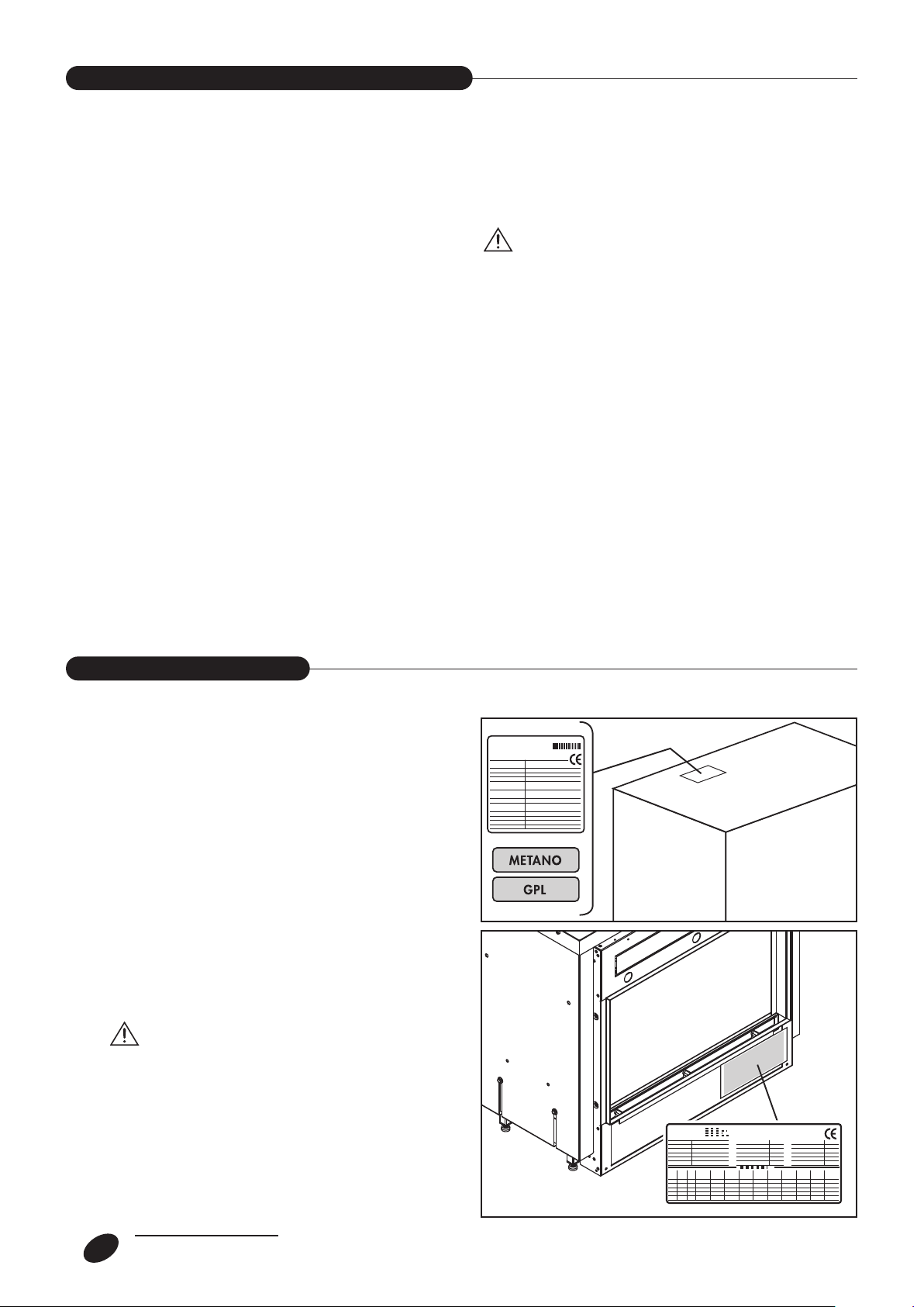
IDENTIFICATION
The appliance can be identified by means of:
- the packaging label
showing the name of the product, the code, the serial
number and the type of gas that can be used.
- The Technical Plate
showing the serial number, the model and the main
technical-performance data.
- The gas type plate
Showing the name of the gas for which the appliance
has been set and regulated. If the type of gas is
changed, this plate must be replaced with that of the
new gas!
Spare parts and/or technical jobs require the
exact identification of the associated model
of appliance.
Tampering with, removing or the absence of the
Technical Plate, etc. does not allow the exact
identification of the product, making any installation and maintenance job difficult.
6
GENERAL
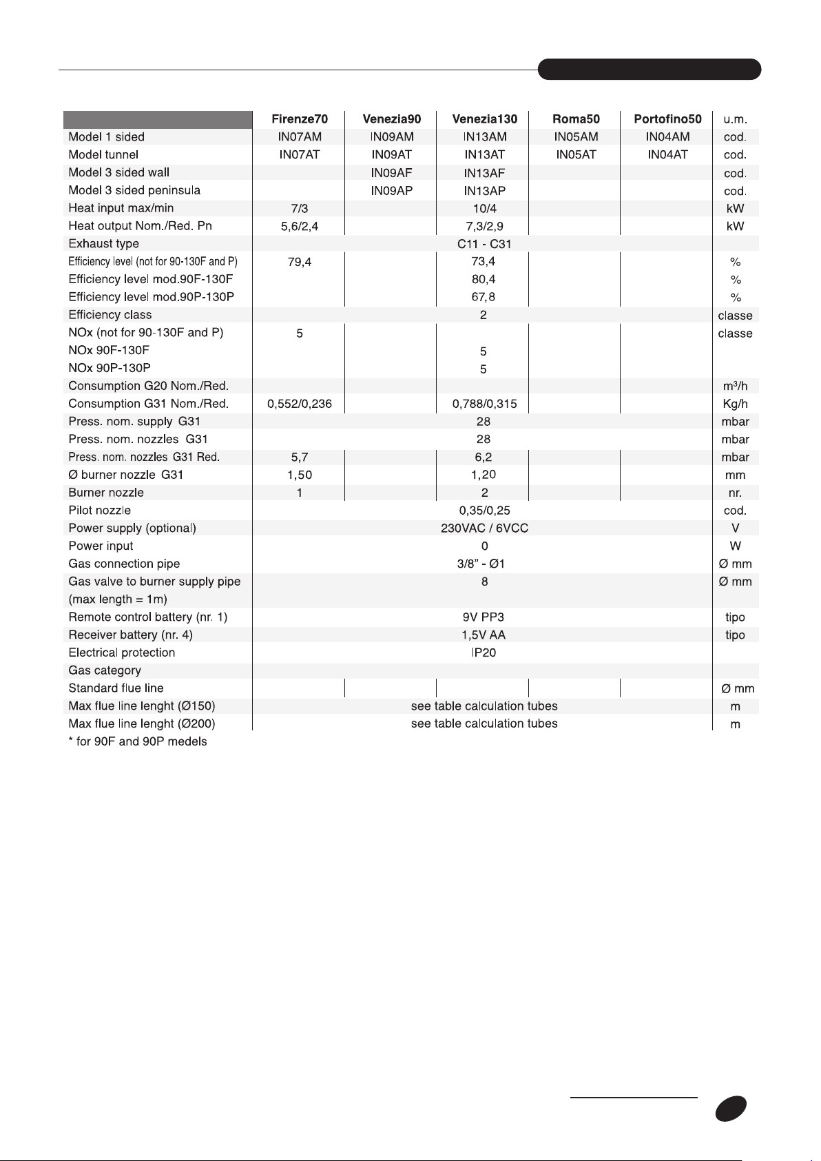
TECHNICAL DATA
150 200 150 150
150/200*
3+
GENERAL
7

ACCESSORIES
8
GENERAL
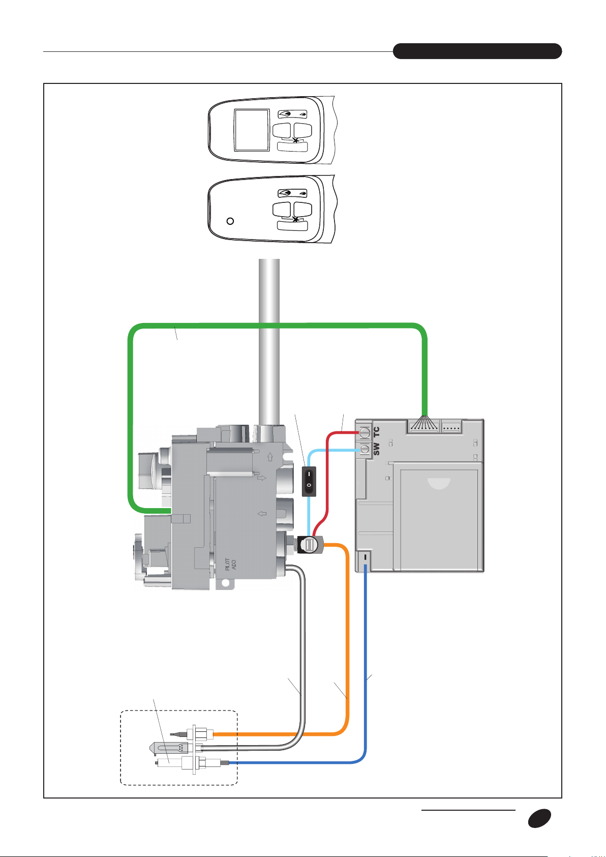
ELECTRICAL SCHEME
Bruciatore pilota
Pilot Burner
VALVOLA GAS
GAS VALVE
Ricevitore
Receiver
Telecomando
Handset
(standard)
Telecomando
Handset
(optional)
Switch On/Off
Cavo accensione
Power cable
Termocoppia
Thermocouple
Termocoppia
Thermocouple
Tubo gas pilota
Pilot gas pipe
GAS output
Cavo connessione
ricevitore valvola.
Power cable
valve receiver.
Elettrodo accensione
Ignition electrode
uscita GAS
GENERAL
9
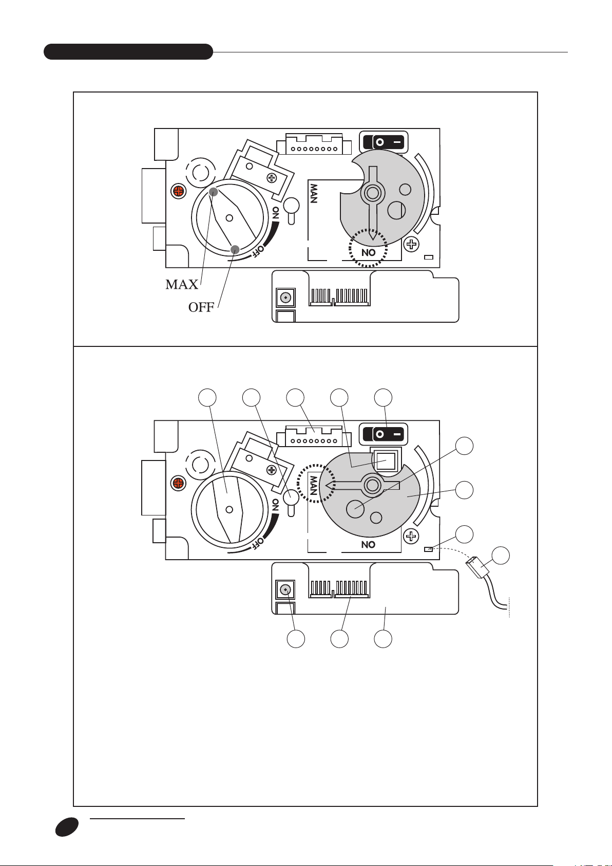
1 - Adjustment knob
2 - MAX gas adjustment screw
3 - Flame control Valve/Board connector
4 - Piezoelectric ignition button (emergency)
5 - O-1 switch
6 - Magnet switch for manual operation (emergency)
7 - Manual operation position knob
8 - Piezoelectric connector wire
9 - Flame control board
10 - Flame control Valve/Board connector
11 - Power socket - 6V DC
12 - Cable to be disconnected from the unit and connect on position 8
MANUAL Operation position
A
utomatic operation position with REMOTE CONTROL
6
7
8
1 4 52 3
91011
12
CONTROL PANEL
GENERAL
10
 Loading...